10A1. Precautions. The York Balanseal
compressors, 2 5/8- and 4-inch bore, are so designed that any competent mechanic can service them in the field. Good judgment should
always be used in the analysis of service
troubles and specific instructions should be
followed as directed.
It is important that the following precautions be observed:
1. Before dismantling the compressor, be
sure that the faulty operation of the installation
is not caused by trouble in some other part of
the system.
2. Dismantle only the part of the compressor
necessary to correct the fault.
3. Never open any part of the compressor
while it is under vacuum; be sure that there
is some pressure inside as indicated by a
reading above zero on the gage. Be sure that
the gage is accurate. If any part of the system
is opened while under vacuum, that is, when
the pressure inside is lower than the pressure
outside, air will enter the system. This air
nearly always contains some moisture, which
freezes and interferes with the operation, or
even causes damage. It is also important that
air or moisture be prevented from coming in
contact with machined parts after they have
been exposed to Freon 12.
4. Internal machined parts of the compressor, such as the valves, pistons, shaft seal, and
crankshaft, must be protected from the atmosphere immediately upon being removed from
the compressor. Corrosion occurs quickly if
this precaution is neglected. As soon as removed, each part must be wrapped in paper.
5. IMPORTANT. To disassemble or reassemble the compressor, use only the tools
specified for the particular operation involved.
10A2. Direction of rotation. The shaft seal
on submarine installations is designed for
counterclockwise rotation of the compressor as
viewed from the flywheel end. The compressor
must not be operated in the opposite direction.
B. OPENING COMPRESSOR FOR REPAIRS
10B1. Pumping down for repairs. Before
opening a compressor for examination or repair, it is necessary to pump down the system.
a. Pumping Freon 12 out of the compressor.
To pump Freon 12 out of the compressor,
proceed in the following manner:
1. Close the suction stop valve.
2. If the compressor is operated normally
under suction pressure control, block the suction pressure switch in its running position.
This can be done without disturbing the adjustment.
Open the compressor discharge valve
about two turns of the stem.
4. Start the compressor and let it run until
the greatest vacuum possible is obtained.
5. Stop the compressor and immediately
close the discharge stop valve. The procedure
outlined in Step 4 and the first part of Step 5
should be repeated if the pressure indicated by
the suction gage rises rapidly to 15 psi or more
above zero pressure, for such a rise indicates
that considerable Freon 12 remains in the
crankcase oil. Do not expect to retain zero
pounds' pressure on the suction gage, because
Freon 12 vapor is continually released from
the oil in the crankcase.
6. After the vacuum is pumped, wait until
the pressure builds up to 2 or 3 pounds above
zero pressure before opening any part of the
compressor or its connections.
7. Before proceeding with any work on the
compressor, see that the main disconnect
switch is open. After examination or repair,
remember to unblock the suction pressure
switch before resuming operation.
65
b. Evacuating air from the compressor. To
evacuate air from the compressor after completing its reassembly, proceed as follows:
NOTE. During examination or repair, the
compressor suction and discharge stop valves
have been closed to trap the Freon 12 charge
in the system.
1. Break the discharge gage valve line to
the atmosphere.
2. Start the compressor and let it run until
the greatest vacuum possible is obtained.
3. Stop the compressor and immediately
crack the suction stop valve to blow Freon 12
gas through the compressor valves and purge
the air above the discharge valve through the
open gage line. Then close the discharge gage
line and the suction stop valve.
C. COMPRESSOR VALVES
10C1. Indications of faulty valves. Faulty
compressor valves in the air-conditioning compressors may be indicated either by a gradual
or sudden decrease in the expected compressor
capacity. Either the compressor fails to pump
at all, or the suction pressure cannot be pumped
down to the proper pressure. This causes the
compressor to run for prolonged periods, or
even continuously. Short shutdown periods
may indicate leaky compressor valves, if the
faulty operation is not caused by any of the
conditions listed above.
10C2. Analysis of faulty valves. Before
opening a compressor for valve inspection or
replacement, the auxiliary man should be definitely sure that the faulty operation of the
system is caused- by the valves. Therefore,
before assuming that the compressor valves
must be serviced, carefully check each of the
following possible causes of trouble:
1. Be certain that the Freon 12 system is
fully charged.
2. Be certain that the expansion valve is in
a normal operating condition.
3. The suction pressure cutout switch should
be adjusted to stop the compressor when the
suction pressure drops to 2 psi; the compressor
should not start until the pressure setting at
which it should start the compressor, 20 psi,
is reached.
4. The temperature control switch (room
type thermostat), provided for the purpose of
cutting off refrigeration in the rooms when the
desired temperature has been reached, closes
the solenoid valve and stops the admission of
liquid to the evaporator.
5. The compressor motor should be run at
its rated speed. A low speed reduces the
capacity of the compressor.
The compressor should not be opened for
inspection until each of the above possible
sources of faulty operation has been eliminated.
The correct method of disassembling and
reassembling each part of the compressor is
outlined below under the respective headings.
10C3. Compressor discharge valves. There
is no satisfactory field method of analyzing the
efficiency of the compressor discharge valves.
except by the process of elimination. The
serviceman must analyze and eliminate all
possible sources of trouble in other parts of
the system before opening the compressor for
valve inspection or replacement.
10C4. Removing the discharge valve assembly. To remove the discharge valve
assembly, proceed as follows (see Figures 7-3
and 7-4):
1. Pump out the compressor.
2. Remove the cylinder head (7), using care
not to damage the thin metal gasket (41). Do
not use a screwdriver or similar tool to pry off
the cylinder head. Tapping the head lightly
around the edge helps to loosen the joint. As
the cylinder head is lifted, the gasket may
adhere to both the head and the discharge
valve plate (8). Use a knife blade or other flat
instrument to help release the gasket.
3. Remove the capscrews (48) that hold the
discharge valve plate and lift off the valve
assembly, using the same precaution with the
gasket (40) as explained in Step 3 above.
4. Handle the gaskets with care, placing
them aside where they will not be damaged.
The same gasket (40), or one of exactly equal
thickness, must be used in replacing the discharge valve assembly. This is important because the thickness of this gasket determines
the clearance between the valve plate and the
66
piston when at the top of its stroke. This
clearance is only a few thousandths of an inch.
10C5. Disassembling the discharge valve
assembly. Whenever the discharge valves are
found to be defective, replace the entire discharge valve assembly with a new one and
return the defective assembly to a tender or
base for repair. Generally, if the valve operation
is faulty, the valve plate as well as the valve
diaphragm is defective; if the valve diaphragm
is broken, the valve plate will be scratched or
marred. In either case, the valve seats on the
discharge valve plate must be relapped. This
lapping process requires highly specialized
machinery and cannot be done in the field.
If disassembling the discharge valve assembly cannot be avoided, proceed as follows (see
Figures 7-3 and 7-4):
1. Remove the cotter pin (12) from the
valve bolt (9).
2. While loosening the castellated nut (11),
hold the valve bolt with a wrench on the fiat
projection above the nut. Take care that the
wrench does not slip and damage the valve or
valve plate.
3. Note that the valve diaphragm (13) seats
on two narrow concentric surfaces machined
on the valve plate. These surfaces are very
finely lapped and must not be scratched.
4. Note that the gasket (9A) seals the joint
between the valve bolt and the under side of
the discharge valve plate.
10C6. Reassembling the discharge valve.
In reassembling the discharge valve, proceed
in the following manner (see Figures 7-3 and
7-4):
1. Thoroughly wash each individual part in
approved cleaning solvent, giving a final rinse
in approved cleaning solvent, and dry in air
without wiping.
2. Place the first valve diaphragm (13) in
position on top of the discharge valve plate,
with the concave side down.
3. Place the diaphragm spacer (14) on top
of the first valve diaphragm.
4. Place the second valve diaphragm on top
of the spacer with concave side up.
5. Place the third valve diaphragm on top
of the second valve diaphragm with concave
side down.
6. Place the valve bolt washer (10) in position with the rounded edge of the washer
against the valve.
7. See that the holes in the discharge valve
diaphragms are in alignment while the assembly is being tightened.
8. Draw the castellated nut firm with a 6
inch wrench, holding the flat projection above
the nut with another wrench. If the cotter pin
hole through the nut does not match the hole
in the valve bolt, try another nut if available;
otherwise dress the face of the nut with fine
emery cloth. Care must be exercised not to
put too much strain on the valve bolt.
10C7. Installing the discharge valve assembly. In installing the discharge valve
assembly, proceed in the following manner
(see Figures 7-3 and 7-4):
1. Thoroughly wash the valve assembly in
approved cleaning solvent. Give the valve
assembly a final rinse in approved cleaning
solvent, and dry in air without wiping.
2. Clean the gaskets, the surface on top of
the cylinder, and the cylinder head.
3. Place the proper thin metal gasket (40) in
position on top of the cylinder.
CAUTION. The thickness of this gasket
determines the clearance between the top of
the piston at the top of its stroke and the
bottom surface of the discharge valve plate.
For this reason it is important to use either
the original gasket or a new gasket whose
thickness is the same as the original. These
gaskets are available in three thicknesses: 0.010
inch, 0.015 inch, and 0.020 inch. When the
discharge plate gasket (40) is in position on
top of the cylinder block, check the clearance
between the surface of the gasket and the
suction valve when the pistons are at the top
of their stroke. The clearance between the top
surface of the gasket and each suction valve
should be 0.015 to 0.025 inch for the 2 5/8-inch
compressor, and 0.015 to 0.030 inch for the
4-inch compressor.
4. Place the discharge valve assembly in
position, making sure that the port through
the plate coincides with the cylinder discharge
port.
5. Fasten the valve plate with the two
capscrews (48), using a wrench with a leverage
that does not exceed 9 inches.
67
6. Place the cylinder head gasket (41) and
cylinder head (7) in position, making sure that
no dirt has fallen on the discharge valves.
Tighten all cylinder head capscrews evenly, to
insure a tight joint and to prevent distorting
the cylinder head or twisting off the capscrew
heads.
IMPORTANT. To insure a tight gasket
joint between the cylinder head and the discharge valve plate without an excessive strain
on the cylinder head capscrews, see that the
gasket surface on the cylinder head is flat.
To determine whether the cylinder head
gasket surface is flat, place the cylinder head
on a surface plate and test the flatness with
a 0.0015-inch thick feeler gage. If the gasket
surface of the cylinder head is uneven, use
a new cylinder head. If no new cylinder head
is available, resurface the gasket surface by
hand scraping.
7. Break the discharge gage valve line to the
atmosphere. Crack the suction stop valve to
blow Freon 12 through the compressor valves,
and purge the air out through the open gage
valve. Close the discharge gage valve line and
the suction stop valve. Then close the discharge gage valve line and the suction stop
valve.
8. Open the discharge stop valve and test for
leaks.
9. If there are no leaks, open the suction
stop valve, and the compressor is ready for
normal operation.
10C8. Compressor suction valves. The compressor suction valves may be checked for
leakage in the following manner:
1. Close the suction stop valve.
2. Start the compressor.
3. Continue to run the compressor by blocking the suction pressure control switch in the
running position. This may be done by means
of a screwdriver placed under the main operation lever. If a vacuum of approximately 20
inches can be readily pumped, as indicated by
the suction gage, the compressor suction valves
are satisfactory.
NOTE. A vacuum cannot be maintained
after the compressor stops, because of the
Freon 12 being released from the oil in the
crankcase.
Do not attempt to check the compressor
suction valve efficiency until after the compressor has been in operation for a minimum
of three days, as it may be necessary for the
valve to wear in.
10C9. Removing the suction valve assembly.
To remove a compressor suction valve, proceed
in the following manner (see Figures 7-3 and
7-4):
1. Pump out the compressor.
2. Remove the cylinder head (7).
3. Remove the discharge valve plate assembly (8).
4. Rotate the flywheel until the piston-from
which the suction valve is to be removed is
about 1 inch below the top of the cylinder, so
that the screwdriver bushing may be inserted
in the cylinder bore.
5. Use the T-handled screwdriver with its
guide bushing, and remove the valve screw (25).
6. Rotate the flywheel until the piston is at
top dead center and remove the valve diaphragms (13A) and the diaphragm spacer (14).
7. Tag each part as it is removed, so that
the parts can be replaced in their original
position.
10C10. Inspection of the suction valve assembly. In inspecting the-suction valve assembly, proceed in the following manner:
1. Examine the valve seats on the piston and
the valve diaphragm. If either of the narrow
concentric valve seats on top of the piston is
marred, the piston must be replaced.
2. Examine the suction valve screw. If the
head is not perfectly round and free from burrs
on the underside and edges, it must be renewed.
A flat side on the screw head is apt to cause
the valve to break.
NOTE. If a suction valve has been broken,
a new suction valve screw should be used with
the new valve.
3. Before replacing a broken suction valve;
be certain that all the small pieces of the
broken valve are accounted for; if necessary,
remove the cylinder. Small pieces of the broken
valve may drop through the suction valve port
in the top of the piston and lodge in the cylinder, in the trunk of the piston, or in the suction
connection between the strainer and the cylinder. If these pieces are not removed, the piston
and cylinder surfaces will be damaged, and the
new suction valves may be cut or broken when
68
the pieces are drawn through the compressor
valves. To protect the compressor against such
damage, the cylinder and suction strainer
should be removed, and the internal parts
thoroughly cleaned. Particular care should be
taken to clean the suction connection between
the suction strainer body and the compressor
cylinders.
NOTE. If a suction valve is only cracked,
or all the parts of a broken valve can be found,
it is not necessary to remove the cylinder.
10C11. Installing the suction valve assembly.
In installing the suction valve assembly, proceed as follows (see Figures 7-3 and 7-4):
1. Thoroughly wash each individual part in
approved cleaning solvent, giving a final rinse
in approved cleaning solvent, and dry in air
without wiping.
2. Place the first valve diaphragm (13A) in
position on top of the piston with the concave
side down.
3. Place the diaphragm spacer (14) on top
of the first valve diaphragm.
4. Place the second valve diaphragm on top
of the spacer with concave side up.
5. Place the third valve diaphragm on top
of the second valve diaphragm with the concave side down.
6. Install the suction valve screw (25)
through the center hole of the valve diaphragms, and screw into the head of the piston
by hand. The suction valve screw may fit
tightly the full length of its threads. With
screwdriver bushing in place, firmly seat the
valve screw with the T-handled screwdriver.
Use careful judgment in tightening this screw.
7. Closely examine the head of the suction
valve screw and remove all traces of burrs from
it. Do not file, scrape, or grind off the burrs
because of the danger that emery dust or metal
filings may get into the cylinder. Peen the
burrs down with a light hammer or small steel
rod. This insures a clean job and does not
impair the strength of the screw as would filing
or grinding.
8. Install the discharge valve plate assembly (8).
9. Replace the cylinder head (7) and prepare
the compressor for operation.
10C12. Discharge valve plate gasket data.
The table below indicates the thickness of the
discharge valve plate gaskets required when
the pistons are flush with or below the top of
the cylinders. This table is to be used only
when installing lead-coated copper gaskets.
Take indicator readings as close as possible to
the suction valve screw.
2 5/8-INCH COMPRESSOR
Piston flush with top of cylinder, use one
0.015 gasket.
Piston flush to 0.005 below top of cylinder,
use one 0.015 gasket.
Piston 0.005 to 0.010 below top of cylinder,
use one 0.010 or one 0.015 gasket.
Piston Clearance with Gaskets in Place
Distance between top of suction valve and a
line horizontal with top of discharge valve
plate gasket: minimum 0.015; preferred 0.020;
maximum 0.025.
4-INCH COMPRESSOR
Piston flush with top of cylinder, use one
0.015 gasket.
Piston flush to 0.010 below top of cylinder,
use one 0.015 gasket.
Piston 0.010 to 0.015 below top of cylinder,
use one 0.010 or one 0.0.15 gasket.
Piston Clearance with Gaskets in Place
Distance between top of suction valve and a
line horizontal with top of discharge valve
plate: minimum 0.015; preferred 0.025; maxi
mum 0.030.
D. COMPRESSOR CYLINDERS
10D1. Removing the cylinders. In removing
the cylinders, proceed in the following manner
(see Figures 7-3 and 7-4):
1. Pump out the compressor.
2. Disconnect the discharge piping at the
compressor.
3. Disconnect the suction piping at the compressor.
4. As soon as each connection referred to in
Steps 2 and 3 is disconnected, close all openings to prevent air and dirt from entering.
5. Carefully wipe all dirt from the cylinders
and around the capscrew heads so that none
is apt to fall into the crankcase when the
cylinder is removed.
6. Remove the discharge valve assembly.
69
7. Rotate the flywheel until one of the
pistons is at the bottom of its stroke.
8. Unbolt the cylinder from the crankcase
and blow off all dirt or paint that may have
been loosened in removing the capscrews.
9. Raise the cylinder enough to insert a knife
blade or other fiat instrument to help release
the gasket (38) from the cylinder. If the cylinder is removed without this precaution, the
gasket may be torn. A new gasket of equal
thickness must be used when the cylinder is
again installed, because the thickness of this
gasket assists in determining the clearance
between the top of the piston, when at the top
of its stroke, and the bottom of the discharge
valve plate.
10. Slowly lift the cylinder straight up, and
at the same time support each piston as, it
leaves the cylinder bore. If an auxiliary man
must do this without assistance, he should pull
the cylinder toward him as it is raised, so that
each connecting rod rests against the crankcase as it leaves the cylinder. This is important,
as the pistons are liable to be damaged if permitted to fall against the edge of the crankcase,
CAUTION. When lifting the cylinder off
the pistons, be careful not to twist it, as this
is liable to bend the connecting rods; a slight
twisting motion exerts considerable bending
force because of the leverage on the rods,
11. Place the cylinder on a clean sheet of
paper or on a clean bench.
10D2. Installing the cylinders. In installing
the cylinders, proceed in the following manner
(see Figures 7-3 and 7-4):
1. Thoroughly wash all parts in approved
cleaning fluid, rinse clean with approved cleaning fluid, and permit to dry without wiping.
2. Make sure that all internal parts are
properly tightened, that the piston rings are
free in their grooves, and that the oil in the
crankcase is clean and covers 1/2 to 3/4 of the
bull's-eye sight glass.
3. See that the gasket surface on the crankcase is clean, dry, and free of oil.
4. Clean the gasket and place it in position
on the crankcase.
CAUTION. The thickness of this gasket
assists in determining the clearance between
pistons and the discharge valve plate. Hence
it is important to use a gasket with a thickness,
equal to the original. These gaskets are available in two thicknesses, 0.010 inch and 0.015
inch. It is necessary to determine whether the
original gasket was 0.010- or 0.015-inch thick.
The correctness of the choice of the gasket is
further checked when Step 9 is reached.
5. Lubricate the pistons and cylinder bores
with new Freon 12 compressor oil, Navy
Symbol No. 2135, or its equivalent.
6. Make sure that the suction and discharge
connections on the cylinder face in the proper
direction to match the adjacent piping; then
with the cylinder held directly above the crankcase, lower it to enter the pistons one at a time.
No difficulty should be encountered if the piston rings are centered and the highest piston
is entered first.
CAUTION. Do not twist the cylinder as it
is lowered, because of the danger of bending
the connecting rods.
7. After all the piston rings are entered, the
cylinder may be pushed steadily down until
the locating pins on the crankcase properly
center it.
8. Bolt the cylinder to the crankcase, carefully drawing all the capscrews evenly.
9. Place the discharge plate gasket (40) in
position on top of the cylinder and check the
clearance between the gasket and each suction
valve when the pistons are at the top of their
stroke. The clearance between the top of the
gasket and each suction valve should be 0.015
inch to 0.025 inch for the 2 5/8-inch compressor;
and 0.015 to 0.030 inch for the 4-inch compressor.
10. Clean and install the discharge valve
plate assembly.
11. Reconnect all the piping connections in
the proper manner.
12. Pump the air out of the compressor.
13. Open the discharge stop valve and test
all joints that were disconnected.
14. If there are no leaks, open the suction
stop valve, and the compressor is ready for
normal operation.
15. Wipe the oil from the outside of the
compressor. The compressor gaskets may then
be examined for oil, as an indication of leakage,
the next time the installation is inspected.
70
E. COMPRESSOR PISTONS
10E1. Removing the pistons. For access to
the pistons, remove the cylinder. (See Figures
7-3 and 7-4.) There is no locking device on
the piston pins. The piston pins are placed
centrally in the holes at assembly, so that the
two ends are clear. Soft metal plugs are provided in each end of the piston pin, so that if
the piston pin works to one side or the other,
the soft plugs prevent scoring of the cylinder
wails.
1. Remove the cylinder (6).
2. Rotate the crankshaft (26) so that the
piston to be removed is at the top of its stroke.
3. Use a wood or soft metal rod to drive out
the piston pin (24). It is best to have a rod
with a countersunk end to fit the rounded end
of the piston pin.
CAUTION. Support the piston centrally
and back it up with a wood block while driving
out the piston pin, in order to cause no strain
on the connecting rod. If this precaution is
neglected, the rod may be bent, due to the
enormous leverage on the rod which is supported only by the crank pin. Even an imperceptible bend in the rod may be sufficient to
cause binding of the piston in the cylinder and
subsequent trouble. Also, unless the piston is
properly supported, it is apt to bump against
the rod and raise burrs on the end of the piston
pin bushing.
4. Place the piston on a sheet of clean paper.
10E2. Installing the pistons. To install the
pistons, proceed in the following manner (see
Figures 7-3 and 7-4):
1. Rotate the crankshaft (26) until the connecting rod to which the piston is to be attached is at the top of its stroke.
2. Clean the parts thoroughly with approved
cleaning fluid, rinse in clean approved cleaning
fluid, and permit to dry without wiping.
3. The piston pins (24) are ground to such
close tolerance that extreme care must be
exercised in lining up the hole in the rod with
the hole in the piston, to prevent raising a burr
on either the piston pin or the hole in the piston, or the bushing in the rod.
CAUTION. Be sure to support the piston
at its middle narrow section and back it up
with a wood block while driving the piston pin
in to prevent bending the rod, or burring the
bushing, as discussed in Section 10E1. The
piston pin is shorter than the diameter of
the piston; be sure to center the piston pin
in the piston so that it clears the cylinder
wall on both sides.
4. See that the rings and ring grooves are
clean, and that the rings are free and snug
fitting in the grooves; then install the cylinder.
F. COMPRESSOR CRANKSHAFT
10F1. Removing the crankshaft. When it is
necessary to remove the crankshaft, the piston,
connecting rods, and crankshaft may be removed as a complete assembly. To remove the
crankshaft proceed in the following manner
(see Figures 7-3 and 7-4):
1. Pump out the compressor.
2. Remove the flywheel (34).
3. Remove the cylinder (6).
4. Remove the shaft seal (31).
5. Unbolt and remove the bearing head (2),
using the two jacking screws in the tapped
holes provided in the bearing head. While
removing the bearing head, keep an even tension on the jacking screws to prevent binding
the head in the crankcase. As the bearing head
comes loose, support the flywheel end of the
shaft to prevent damage to the shaft when the
weight of the bearing head is supported only
by the shaft.
6. While holding the pistons so that none
falls against the crankcase and is damaged,
slide the shaft forward out of the rear main
bearing. Work the flywheel end of the shaft
through the opening left by the bearing head,
and at the same time raise the rear end of the
shaft until it clears the back edge of the crankcase. The assembly may then be lifted out and
placed on a sheet of clean paper.
10F2. Installing the crankshaft. To install
the crankshaft assembly, proceed in the following manner (see Figures 7-3 and 7-4):
1. See that the inside of the crankcase (1) is
clean. Clean all parts with approved cleaning
71
fluid, rinse in clean approved cleaning fluid,
and dry without wiping.
2. Slip the shaft in place in the same way as
in removing it.
3. Use the same gasket (39), or one of the
same thickness, when installing the bearing
head. This gasket determines endwise clearance in the shaft. The gasket for the 2 5/8-inch
compressor is minimum 0.007, preferred 0.009,
maximum 0.012. The gasket for the 4-inch
compressor is minimum 0.009, preferred 0.011,
maximum 0.014.
4. Slide the bearing head over the shaft and
use particular care to enter it squarely. This
bearing head fits with small clearance in the
crankcase opening, and time is saved if it is
carefully started. While forcing the bearing
head into place, tap lightly all around the edge
of the head flange. Use two cylinder head capscrews
to pull the bearing in until the bearing
head capscrews engage the thread.
5. As soon as the capscrews engage the
thread, use them to draw the head in place,
being careful to draw evenly on all screws.
6. While pushing against the flywheel end
of the crankshaft, check with a thickness gage
the clearance between the face of bearing head
(2) and the shoulder on the crank throw. This
clearance must not be less than 0.007 inch nor
more than 0.012 inch for the 2 5/8-inch compressor; and not less than 0.009 nor more than
0.014 inch for the 4-inch compressor. To adjust
this clearance, change the thickness of gasket
(39) between bearing head and crankcase.
7. Install the cylinder (6).
8. Install the shaft seal. Do not neglect to
adjust the shaft seal if new bearings, shaft, or
seal have been installed.
G. CONNECTING RODS
10G1. Removing the connecting rods. If a
connecting rod becomes defective in any way,
the complete connecting rod should be replaced
with a new one. The piston pin bushing cannot
be properly applied to the rod in the field, and
no field repair of the crank end bearing should
be attempted. These bearings are not adjustable, and any attempt made in the field to fit
by filing is apt to result in excessive clearance
of incorrect rod lengths, which might cause
damage to the compressor valve assembly. To
remove the connecting rods, it is advisable to
remove the crankshaft assembly. To remove a
connecting rod, proceed in the following manner (see Figures 7-3 and 7-4):
1. Remove the crankshaft assembly (26).
2. Remove the piston (21).
3. Remove the connecting rod bolts (16),
wire keepers (18), and castellated nuts (11).
4. To loosen the connecting rod bearing cap,
insert a drift pin in the dowel pin holes that
extend through the rod side of the bearing.
Then tap the drift pin.
10G2. Installing the connecting rods. To
install the connecting rods, note that the parts
of each rod are correspondingly lettered or
numbered, and proceed in the following manner
(see Figures 7-3 and 7-4):
1. Clean all parts with approved cleaning
fluid, rinse with approved cleaning fluid, and
let dry without wiping.
2. Assemble the rod on the crank pin with
the dowel pins properly entered.
3. Draw the connecting rod bolts (16) finger
tight only. Then insert drift pin through the
holes which extend through the bearing cap
and tap lightly on the dowel pins. This locates
the cap accurately while the bolts are still loose
enough to permit the cap to shift.
4. Tighten the bolts evenly and tap again on
the dowel pins. Peen the holes as they were
originally, to lock the dowels.
5. If the pin hole in the nut does not align
with the hole in the bolt, dress the face of the
nut with emery cloth. Do not back off on the
nut to align the holes.
6. Attach the piston (21) to the rod (15).
NOTE. It may be more convenient to install the crankshaft assembly before attaching
the pistons to the rods.
7. Install the crankshaft assembly and complete the assembly of the compressor.
H. CRANKSHAFT BEARINGS
10H1. Front main bearing. The crankshaft
main bearings cannot be repaired. The only
reason for removing either crankshaft main
bearing is to replace it with a new one when
72
it has become worn to such an extent that it
no longer gives satisfactory operation.
a. Removing the front main bearing. To
remove the front main bearing, proceed in the
following manner:
1. Remove the bearing head.
2. With a wood or soft metal rod, drive the
defective bearing out of the bearing head.
b. Installing a new front main bearing. To
install a new front main bearing, proceed in
the following manner:
1. Clean the bearing and head with approved
cleaning fluid, rinse with clean approved cleaning fluid, and let dry without wiping.
2. Oil the bearing and hole in the head with
new Freon 12 compressor oil, Navy Symbol
No. 2135, or equivalent.
3. Carefully enter the bearing squarely in
the hole, and be sure that the bearing key, cast
on the bearing, lines up exactly with the key
way in the bearing head. To do this, lay a steel
scale or similar straightedge along the key on
the bearing, and scribe a line the full length of
the bearing. Enter the bearing with this line
placed on the corner of the keyway.
4. Drive the bearing into the bearing head,
tapping lightly all around the bore to keep it
from binding. While driving the bearing in,
use a block of wood to protect the end of the
bearing to prevent raising burrs or distorting
it. When the bearing is in place, the flange of
the bearing must be tight against the bearing
head.
5. Install the bearing head and complete the
assembly of the compressor.
10H2. Rear main bearing. To remove the
rear main bearing, proceed in the following
manner:
1. Remove the crankshaft assembly.
2. Use a blunt chisel to crush the bearing
flange near one of the oil grooves. After the
bearing is crushed, it may be withdrawn. Use
care not to damage the bearing bore in the
exchange.
3. Place the new bearing in position, following the instructions given for the front main
bearing.
4. Install the crankshaft, and complete the
assembly of the compressor.
NOTE. Another method of removing the
rear bearing is by using a puller. The puller
can be constructed as follows: Use a tap that
can be threaded into the bearing and weld a
round piece of 1-inch steel stock to it. Thread
the other end of the steel rod. The rod should
be long enough to extend about 3 inches
through the front opening of the crankcase. A
cross-bar drilled to fit the 1-inch rod is placed
across the front of the crankcase in a horizontal
position. Screw the tap into the bearing and
take a strain on the rod by screwing a 1-inch
nut on the free end of the shaft, taking up
very slowly. Care should be taken that the tap
is screwed into the bearing far enough so that
it does not pull out when tension is applied to
the puller.
I. OIL SIGHT GLASS
10I1. Removing the oil sight glass. The only
reasons for which the glass is removed are a
broken glass or defective gaskets. If the glass
is broken so that pieces may have dropped
inside the crankcase, it is necessary to remove
the cylinder and clean the inside thoroughly.
To remove the oil sight glass, proceed in the
following manner (see Figures 7-3 and 7-4):
1. Pump out the compressor.
2. Attach a piece of tubing to the oil drain
valve and drain the oil into a bucket. Avoid
spilling oil on the deck.
3. Remove the oil sight nut (42), taking
care not to destroy the spanner wrench slots
in the nut.
4. Insert the tip of a knife blade under the
washer (43) and gaskets (45) to loosen them.
10I2. Installing the oil sight glass. To install
the sight glass, proceed in the following manner:
1. Clean all the parts with approved cleaning
fluid, rinse with clean approved cleaning fluid,
and let dry without wiping.
2. Arrange the parts as originally assembled
and tighten the lock nut.
3. Pump clean oil into the crankcase.
4. Pump the air out of the crankcase.
73
J. FLYWHEEL
10J1. Removing the flywheel. To remove the
flywheel, proceed in the following manner (see
Figures 7-3 and 7-4):
1. Open the compressor disconnect switch.
Remove the V-belts.
2. Unscrew the flywheel lock nut and mount
the flywheel puller. Tapped holes are provided
in the flywheel hub (34) for the pulley screws.
3. Apply even tension on the screws until
the flywheel is free on the tapered shaft. Remove the flywheel and save the Woodruff key.
10J2. Installing the flywheel. To install the
flywheel, proceed in the following manner (see
Figures 7-3 and 7-4):
1. Mount the flywheel (34) on the shaft
with the Woodruff key (28) in place.
2. Draw the flywheel tight on the tapered
shaft by means of the lock nut (27); do not
drive the flywheel into place because of danger
of damage to the rear main bearing and to the
shaft seal adjustment.
3. Be sure that the lock nut is tight. On
some compressors, the lock nut is locked by
means of a cotter pin (140). If the cotter pin
cannot be inserted, remove the nut and dress
the face of the nut with emery cloth. Do not
back off on the nut to align the cotter-pin holes.
4. Put on the V-belts, and the compressor is
ready for operation.
K. COMPRESSOR CRANKSHAFT SEAL
10K1. The shaft seal. The lubricating oil in
the compressor fills the crankcase to a level
just above the top of the crankshaft bearings.
Therefore, a seal is necessary to prevent the
oil from leaking out between the shaft and its
bearing.
The rear end of the shaft, that is, the end
opposite the flywheel or power end, is completely enclosed by the one-piece crankcase.
No oil can leak from this end, so only one seal
is needed. (See Figures 7-3 and 7-4.)
The seal mechanism is composed of two
parts, a collar (30) rotating with the shaft, and
a diaphragm assembly (31). The diaphragm
is stationary, being rigidly fixed to the crankcase, and carries a ring similar to the shaft
collar. There are really two individual parts
to this seal, a rubbing seal part and a non
rubbing seal part. They are described separately.
a. Rubbing seal. The contact face between
collar and ring, at right angles to shaft axis, is
the rubbing seal, the two parts having been
accurately lapped together at the factory. Since
the ring is stationary, while the collar rotates,
the two parts are in contact under pressure.
The rubbing contact thus set up between them
must be lubricated. Lubrication is facilitated
by a spiral line of small pockets or holes bored
in the ring face, which insures that oil flowing
into the seal is carried properly across the
whole contacting face.
This spiral line of holes will, of course, differ
in direction of winding, according to whether
the rotation is clockwise or counterclockwise.
Submarine installations use counterclockwise
rotation. The outermost hole of the spiral must
be in the five o'clock position, as observed by
the operator facing the flywheel, when the diaphragm is installed. The small amount of oil
required to lubricate the rubbing surfaces, after
passing the seal, is carried to the compressor
base from the seal cover plate by an oil drain
pipe (5).
The success of this seal depends upon the accuracy of the machining and lapping together
of the two contact surfaces and upon the pressure of the ring against the collar maintained
by the diaphragm. The action of the diaphragm
in producing this pressure is described in Sections 10K5 and 10K6.
b. Nonrubbing seal. The shaft collar (30)
is pressed against a shoulder of the shaft by
the spring diaphragm, acting through the seal
ring (31). The collar is keyed stationary to the
shaft by a small steel ball which projects half
way into each. The face between collar and
shaft shoulder, that is, opposite the rubbing
face, is also a seal, called the nonrubbing seal.
This must be an absolute seal, and the collar
must therefore be lapped to the crankshaft collar with the greatest care.
10K2. Shaft seal leakage. For the reason
explained previously, a small amount of oil
74
may be expected to seep from the seal. Before
compressor is replaced because of apparent
oil leakage from the shaft seal, consider the
following (see Figures 7-3 and 7-4):
1. Do not use a halide torch to test the shaft
seal for Freon 12 leaks. Oil from the seal contains some Freon 12, the release of which
causes a false indication if the seal is tested
with a halide torch.
2. The oil leakage from the shaft seal may
be considered excessive if the compressor requires an additional charge of oil within a
period of six months. Before it is assumed that
the oil has leaked past the seal, be certain that
the design of the cooling system has not caused the oil to be trapped in the evaporator coils.
in general, series feed evaporators, or parallel
feed evaporators with thermal expansion
valves, permit oil to return to the compressor
with the Freon 12 gas after the initial oil requirement of the evaporators has been satisfied.
3. If oil occasionally spurts from the shaft
seal, the fault is probably due either to the
system's hook-up or to the operating conditions rather than to the seal. If this condition
occurs, be certain that the arrangement of the
system does not permit an excessive accumulation of oil or liquid Freon 12 in the compressor crankcase. Liquid Freon 12 may tend to
accumulate in the compressor crankcase when
the temperature around the compressor is
lower than the temperature in the evaporator
coils. This condition may exist during the
winter months if the compressor is in an unheated room.
4. IMPORTANT. Do not assume that an
apparent accumulation of oil on the compressor base indicates an excessive leakage of oil
from the shaft seal. What may appear to be a
large quantity of oil from the shaft seal may
in reality be some of the condensate from the
compressor suction line with a film of oil over
it, oil from the compressor motor, or a mixture
of both. Rather than judge the shaft seal leakage by the mixture of oil and water on the
compressor base, check the compressor crankcase oil level to determine the amount of oil
actually remaining in the crankcase. If the oil
has not dropped appreciably below the normal
level, it is safe to assume that the shaft seal
is not leaking.
When excessive leakage at the shaft does
exist and replacement is necessary, both shaft
seal collar (30) and shaft seal assembly (31)
must be replaced. Do not attempt to replace
one part without also replacing the other.
These parts are lapped together and are not
interchangeable.
10K3. Removing the shaft seal. To remove
the shaft seal, proceed in the following manner (see Figures 7-3 and 7-4):
1. If the shaft seal is broken or permits an
excessive leakage of oil, do not attempt to
pump out the Freon 12 contained in the compressor, because air containing moisture may
be drawn into the system through the damaged
seal. When this condition exists, close the compressor suction and the discharge stop valves,
and bleed the pressure to the atmosphere
through the pressure gage valves.
2. Attach a piece of tubing to the oil drain
valve and drain the oil from the crankcase into
a bucket. As the oil is saturated with Freon
12, it foams considerably while being drained.
Avoid spilling oil on the deck. Leave the oil
drain valve open while working on the seal so
that Freon 12 escaping from the oil remaining
in the crankcase cannot build up a pressure
sufficient to blow out the seal unexpectedly
while removing it.
3. Remove the V-belts and flywheel (34).
NOTE. After removing the flywheel lock
nut (140), rotate the shaft until the keyway
is on top. This brings the shaft seal collar
locating ball (29) on top so that the ball does
not drop out and get lost when the seal collar
is removed.
4. Unbolt and remove the shaft seal cover
plate (4).
5. Carefully remove the shaft seal assembly
(31) by grasping it with the fingers. If this
assembly is not easily dislodged, work the
shaft in and out while tapping lightly all
around the edge of the assembly. If this fails
to loosen the shaft seal assembly, create a
slight pressure in the compressor crankcase
by opening the suction or discharge stop valve;
press against the seal to prevent it from being
blown from the compressor.
CAUTION. When the shaft seal assembly
75
is removed, the shaft seal collar (30) usually
follows it. As the shaft seal assembly is with
drawn with one hand, support the shaft seal
collar with the other, holding the collar with
the thumb and one finger on its edges. Be
careful not to drop either part and do not
touch the sealing surface of the seal collar or
seal ring of the shaft seal assembly. Lay the
parts on a sheet of clean paper.
6. Do not disturb the shaft seal diaphragm
gaskets (37), except to remove any thin edges
that may have been squeezed out.
7. Save the shaft seal collar locating ball
(29). If necessary, this ball may be lifted from
its socket with a toothpick or any small sharpened piece of wood.
10K4. Repairing the shaft seal. Both the
shaft seal collar (30) (see Figures 7-3 and 7-4),
and the shaft seal assembly (31) must always
be renewed when either is renewed. These
parts are furnished in sets and should not be
separated.
a. Faulty shaft seal. A faulty shaft seal may
be attributed to any one or a combination of
the following causes:
1. Ruptured seal diaphragm. This causes the
complete failure of the shaft seal, and necessitates replacement of the shaft seal assembly.
2. Dirt between the seal surfaces. Small
particles of dirt between the seal surfaces can
be readily removed by lapping.
3. Seal surfaces cut or scored. Unless the
defect can be completely removed by lapping,
the seal assembly (31) and the seal collar (30)
must be replaced. The shaft shoulder is
hardened; if the ground surface is damaged
beyond field repair, the crankshaft (26) must
be replaced.
4. Seal surfaces not parallel. To determine
whether or not the seal surfaces are parallel,
wash the surfaces with approved cleaning fluid,
permit them to dry without wiping, apply a
small amount of Prussian blue, and then rub
the surfaces together. Unless the surfaces can
be lapped to form a full contact of color over
the whole surface of the seal, the seal assembly
(31) and the seal collar (30) should be replaced.
5. Incorrect shaft seal tension. A definite
initial deflection of the shaft seal diaphragm
is essential to maintain the correct pressure
between the seal surfaces.
b. Lapping the shaft seal collar to the shaft
shoulder. To lap the shaft seal collar to the
shaft shoulder, proceed in the following manner (see Figures 7-3 and 7-4):
1. Clean the surface of the shaft shoulder
with a chamois or hard cloth, saturated with
approved cleaning fluid. Wash the shaft seal
collar in approved cleaning fluid.
2. Lap the back of the shaft seal collar (30)
to the crankshaft shoulder. It is important that
this lapping be done carefully and thoroughly
because this joint must be an absolute seal.
IMPORTANT. Use levigated alumina,
jeweler's rouge, or powdered Bon Ami, mixed
with Freon 12 compressor oil, Navy Symbol
No. 2135, or equivalent, to form a smooth
paste. Use the paste sparingly to avoid getting
it into the shaft bearing. As the lapping operation proceeds, use progressively thinner paste
until only oil is used. When the lapping is
completed, the shaft seal collar should be in
position on the shaft, so that the recess for the
shaft seal collar locating ball (29) is opposite
the corresponding recess in the shaft shoulder.
3. After lapping, thoroughly clean the shaft
shoulder with a piece of chamois or clean hard
cloth saturated with approved cleaning fluid,
and let it dry without wiping. With the shaft
shoulder and the shaft seal collar perfectly
clean and dry, rub the two surfaces against
each other as a final lapping operation. End
the final lapping with the shaft collar in position on the shaft so that the recess for the
shaft seal collar locating ball (29) is opposite
the corresponding recess in the shaft shoulder.
4. The surfaces are properly lapped when
the surface of both the shaft shoulder and the
shaft seal collar form a perfect contact and
are free from scratches or other imperfections.
It is preferable to make this examination with
the aid of a good magnifying glass.
IMPORTANT. Do not lap a new shaft
collar to a new shaft seal ring. This is done at
the factory. However, if required, a used shaft
seal assembly may be lapped to a shaft seal
collar in the same manner as explained earlier.
10K5. Installing the shaft seal. IMPORTANT. The performance and life of the shaft
seal depend upon the care with which the
following instructions are observed. The importance of the proper diaphragm tension and
76
the limitations as stated in these instructions
should not under any circumstances be over
looked.
When assembled, the shaft seal diaphragm
must be under a definite tension. This tension
depends upon the deflection secured by bolting
the shaft seal cover plate (4, Figures 7-3 and
7-4) over the diaphragm with the proper thickness of gaskets (37) in the gasket recess. The
thinner the gaskets used, the greater the
deflection, and vice versa.
The gaskets are available in three normal
thicknesses: 0.005 inch, 0.010 inch, and 0.015
inch. However, these gaskets vary from 0.014
inch to 0.016 inch, so that different thicknesses
can be secured by combining gaskets of varying thicknesses.
1. If a new shaft seal assembly is used, lap
the shaft seal collar (30) to the crankshaft
shoulder.
2. Clean the sealing surface of the shaft
shoulder with a chamois or hard cloth, saturated with approved cleaning fluid, and let it
dry without wiping.
3. Thoroughly wash each part, taking particular care to clean with a matchstick the
small holes in the sealing face of the shaft seal
assembly (31). Rinse the parts in approved
cleaning fluid, and let them dry in air without
wiping. Any discoloration on the sealing surfaces of either shaft seal assembly or shaft seal
collar should be removed with a soft pencil
eraser. These parts must then be washed again
in approved cleaning fluid.
CAUTION. After the final rinse, do not
touch the sealing surfaces.
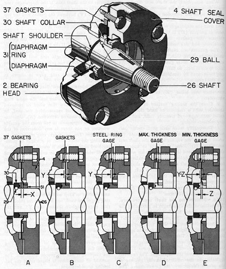
10K6. Determining the shaft seal pressure.
The action of the diaphragm in producing the
required pressure between the seal ring and
the seal collar is illustrated in Figure 10-1.
When bolted on, the shaft seal diaphragm
must cause the diaphragm ring to press against
the shaft collar. This pressure depends upon
the deflection given to the diaphragm when
the shaft seal cover plate (4, Figures 7-3 and
7-4) is bolted over the diaphragm. The required
deflection is the result of having gaskets of
the proper thickness in the gasket recess. The
thinner the gaskets, the greater the deflection,
and vice versa. In Figure 10-1, Sketch A, this
deflection (X) is shown exaggerated.
When the seal cover plate is removed, the
diaphragm, being of spring metal, recovers
from the deflection, standing flat and perpendicular to the shaft axis. If the diaphragm ring
is held in contact against the shaft collar, there
is a space (Y) between the gasket and the top
of diaphragm, exactly equal to the deflection
(X), as shown in Sketch B.
A steel ring gage (of the shape of such a
gasket) can now be placed between the gasket
and the diaphragm. If the ring gage has exactly
the thickness (Y), the whole seal can be bolted
together. The diaphragm ring will touch the
shaft collar but will not press against it because
the diaphragm will have no deflection. This
assembly with steel ring gage is shown in
Sketch C.
If the operator knew that the conditions
shown in the assembly of Sketch C were a
result of a chosen gasket and the same ring
gage, he would know that when he removed
the ring gage and reassembled the seal, he
would get the desired deflection (X). Unfortunately, it is impossible to tell from the outside
whether or not there is any deflection of the
diaphragm. The diaphragm ring might just be
touching the shaft collar, or it might be pressing hard against it, but it would be impossible
to tell which. However, by using two different
ring gages instead of one, the operator can
find out by the following method:
First, it is obviously impossible always to
select a gasket combination of absolutely the
correct thickness. A certain tolerance must be
permitted. This tolerance, however, is limited,
and in order to keep within its limits two steel
ring gages are used, one a maximum thickness
ring gage (slightly thicker than Y), and the
other a minimum thickness ring gage (slightly
thinner than Y). A comparison of these two
gages shows the limited tolerance permitted
and the extreme care with which the gaskets
must be selected.
Moreover, by the use of these two ring
gages, the operator determines whether or not
the diaphragm has the proper deflection. The
method of using them is based upon the following considerations:
If the seal is assembled with the maximum
ring gage on the proper thickness of gaskets,
that is, with the same gaskets referred to in
77
Figure 10-1. Enlarged view of crankshaft seal.
78
Sketches A, B, and C, the shaft seal ring is
held away from the shaft seal collar (30), as
shown in Sketch D. This condition is easy to
observe, because the shaft seal ring can be
moved perceptibly inward toward the seal
collar; a few thousandths of an inch can be
perceived.
If the seal is assembled with the minimum
thickness ring gage on the same thickness of
gaskets, the shaft seal ring is held firmly
against the shaft seal collar (3) with a slight
deflection of the diaphragm, as shown in Sketch
E. This condition can also be easily observed
because the shaft seal ring cannot be moved,
and when tapped lightly with the point of a
screwdriver, or similar small steel rod, it rings
with a solid metallic sound, being held firmly
against the seal collar.
Hence, since the thickness of the maximum
thickness ring gage is equal to the maximum
permissible deflection, any gasket combination
that provides a definite perceptible movement
of the shaft seal ring when assembled with the
maximum thickness ring gage, and that responds with a solid metallic sound on tapping
when assembled with the minimum thickness
ring gage, is within the allowable limits.
10K7. Adjusting the shaft seal. The correct
maintenance of a perfect seal depends upon
the care with which the adjustment is made
to produce the proper pressure. First, be sure
that Section 10K6 is thoroughly understood.
Then follow the routine given below, omitting
no steps (see Figure 10-1):
1. After the shaft seal collar (30) has been
lapped to the shaft shoulder (this lapping
operation is, of course, unnecessary if the
original shaft and shaft seal are installed, wash
all parts with approved cleaning fluid. Use
care to clean with a matchstick the small holes
in the sealing face of the shaft seal ring. Rinse
the parts in approved cleaning fluid and let
them dry in air without wiping. Any discoloration on the sealing surfaces of either shaft
seal ring (31) or shaft seal collar (30) should
be removed with a soft pencil eraser. These
parts must then be washed again in approved
cleaning fluid.
CAUTION. After the final rinse, do not
touch the sealing surfaces.
2. Place a trial thickness of gaskets (37) in
the gasket recess. The original gaskets, or
some of the same total thickness, should be
used for the first trial, as they are nearly correct for the new parts.
3. Place the maximum thickness ring gage
in the recess on the gaskets.
4. Place in position the locating ball (29),
the seal collar (30), and the seal assembly (31),
taking care not to touch or mar the sealing
surfaces.
5. Bolt the seal cover plate (4) in position,
taking care to pull the capscrews evenly all
the way around and as tight as if assembling
the seal for normal operation.
6. With a screwdriver, or other small steel
rod, push in on the seal ring. If the seal ring
can be moved in perceptibly, the thickness of
the gasket combination chosen is greater than
the minimum permissible. That is, the gasket
is not too thin, but it may be too thick; this
is determined when checked with the minimum
thickness ring gage. If the seal ring cannot be
moved in perceptibly, tap it lightly with the
screwdriver. If this tapping produces a solid
metallic sound, the gasket is too thin, and
further trial is necessary with thicker gaskets.
However, if the tapping produces a hollow,
loose sound, the sealing may be just touching
or separated from the seal collar by only a
fraction of a thousandth of an inch. This indicates that the thickness of the gaskets is close
to the minimum permissible, and a gasket
combination of 0.001 inch or 0:002 inch thicker
would be better.
7. When a combination of gaskets is found
that, when assembled with the maximum
thickness ring gage, permits the seal ring to
be moved perceptibly, remove the maximum
thickness ring gage and reassemble the seal
with the minimum thickness ring gage in place
taking care to draw the capscrews evenly all
around and as tight as if assembling the seal
for normal operation.
8. With a screwdriver, or other small steel
rod, tap on the seal ring. If this tapping produces a solid metallic sound, the gaskets chosen
are correct and no further trial is necessary
However, if the tapping produces a hollow
loose sound, the gasket thickness is too great
and further trial is necessary with thinner
gaskets.
79
9. If further trial with thinner gaskets is
necessary when checking with the minimum
thickness ring gage, a recheck must be made
with the maximum thickness ring gage.
10. This alternate checking with maximum
thickness ring gage must be repeated until
such combination of gaskets is found that,
when checked with the maximum thickness
ring gage, permits the seal ring to be moved
perceptibly; or causes it to produce a hollow,
loose sound when tapped; or when checked
with the minimum thickness ring gage, causes
it to produce a solid metallic sound when
tapped.
11. When the proper thickness of gaskets
has been determined, proceed with the installation of the shaft seal. Refer to Section 10K1.