4N1. General description of the packing gland
assemblies. The eyepiece box (11, Figure 4-29)
is provided with one stadimeter transmission
shaft packing gland assembly of either the
spring or modified hycar type, plus four spring-loaded type packing gland assemblies. Each
assembly allows passage of a rotating shaft and
maintains the hermetical seal around each shaft,
used in the eyepiece drive or the focusing
mechanism, the rayfilter drive, the prism tilt,
the change of power mechanism, and the
stadimeter transmission shaft.
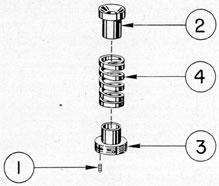
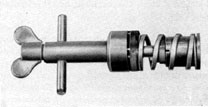
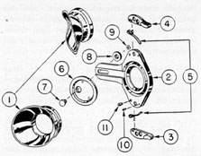
4N2. Description of the stadimeter transmission
shaft packing gland assembly (spring type). Figure
4-30 shows this packing gland assembly. All
bubble numbers in this section refer to Figure
4-30 unless otherwise specified.
Ill. No.
Drawing Number
Num- ber Re- quired
Nomenclature
1
P-1310-39
1
Spring retainer lockscrew
2
P-1405-7
1
Packing gland
3
P-1405-8
1
Spring retainer
4
P-1405-9
1
Packing gland spring
a. Packing gland. The packing gland (2)
is made of phosphor bronze and, is 0.937 inch
in length. It is cylindrical with a reamed hole
in its center axis. The external surface consists
of an undercut section with a large shoulder a few
thousandths-inch smaller than the bored diameter of the eyepiece box base stuffing box
chamber. The undercut section is a loose fit
in the packing gland spring (4). The reamed
hole of the packing gland is a sliding fit on the
stadimeter transmission shaft (22, Figure 4-27).
The large shoulder is chamfered at 30 degrees from the
reamed hole axis to contact sufficient flax
packing, thus forcing the packing into the
similarly chamfered shoulder seat in the bored
diameter of the stuffing box chamber under
tension of the packing gland spring (4). The
compression of the packing between the two
chamfered seats causes the packing to adhere
around the stadimeter transmission shaft (22,
Figure 4-27) thereby permitting its rotation and
providing a hermetical seal of this joint.
b. Packing gland spring. The packing
gland spring (4) is made of chrome silicon
manganese steel alloy, having a free length of
1.500 inches. The upper part of the spring fits
loosely over the undercut section of the packing
gland (2) and rests against its large shoulder
lower face. The lower part is a loose fit on the
small shoulder and rests on the medium shoulder
face of the spring retainer (3). The external
diameter of the spring is a loose fit in the bored
stuffing box chamber in the eyepiece box base
(11, Figure 4-29).
c. Spring retainer. The spring retainer (3)
is made of phosphor bronze and is 0.810-inch
in length. It is undercut with a long section
having a nominal wall thickness, and serves
as a guide for the packing gland spring (4). The
medium shoulder serves as the seat for the spring.
The large shoulder periphery is threaded to
screw into the internal threaded stuffing box
chamber in the eyepiece box base (11, Figure
4-29).
Two holes are drilled in the threaded periphery
along a diameter, and the wall has a narrow
slot cut halfway through the shoulder to these
161
drilled holes. In the center of the slotted section,
a perpendicular tapped hole is provided near
the periphery for the insertion of a lockscrew
(1). When tightened, this lockscrew spreads the
narrower slotted half of the wall away from the
heavier part, and secures the spring retainer
in the internal threaded section in the stuffing
box chamber. The center axis is bored to provide
sufficient clearance for the female tang coupling
(68, Figure 4-24) of the stadimeter housing
assembly, for its interconnection with the male
tang section of the stadimeter transmission
shaft (22, Figure 4-27). The face of the spring
retainer is provided with four equally spaced
shallow holes, to accommodate the projecting
prongs of a special wrench.
Upon the loading of this packing gland with
9 inches of 1/4-inch flax packing, there is an
initial compression of 1/8-inch required of the
packing gland spring (4) before the spring
retainer threads engage in the internal threaded
section of the stuffing box chamber. This allows
the small undercut shoulder of the spring
retainer a 1/16-inch metal to metal contact or
solid compression with the packing gland and
places a 3/8-inch compression on the packing
gland spring (4) when the face of the spring
retainer is flush with the eyepiece box base.
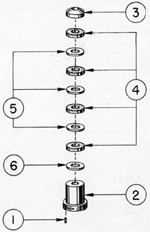
4N3. Description of the stadimeter transmission
shaft packing gland assembly (modified hycar type).
Figure 4-31 shows this packing gland assembly.
All bubble numbers in this section refer to
Figure 4-31 unless otherwise specified.
Ill. No.
Drawing Number
Num- ber Re- quired
Nomenclature
1
P-1310-39
1
Packing retainer lockscrew
2
P-1468-2
1
Packing retainer
3
P-1468-3
1
Gland filler piece
4
P-1468-4
4
Hycar packing spacers
5
P-1468-5
3
Brass spacer washers (0.020 inch)
6
P-1468-6
1
Packing retainer brass washer (0.060 inch)
a. Gland filler piece. The gland filler piece
(3) is made of rolled brass rod and is 0.338-inch
in width. It is cylindrical with the periphery
several thousandths-inch smaller than the bored
diameter of the eyepiece box base stuffing box
chamber. The axis is provided with a reamed
hole a sliding fit on the stadimeter transmission
shaft (22, Figure 4-27). The upper face is
chamfered at 30 degrees. This gland filler piece serves
to fill the 30 degrees chamfered seat of the stuffing
box section, and has a flat shoulder upon which
the uppermost hycar packing spacer rests under
tension.
b. Hycar packing spacers. The four hycar
packing spacers (4) are made of 1/8-inch special
synthetic rubber sheet. Each spacer is cut
cylindrical, with the external diameter 0.007-inch
larger than the bored diameter of the eyepiece
box base stuffing box chamber, while the center
hole is 0.007-inch smaller than the stadimeter
transmission shaft (22, Figure 4-27).
c. Brass spacer washers. The three brass
spacer washers (5) are made of 0.020-inch
thick brass. The washers are cylindrical, having
a 0.006-inch smaller diameter than the bored
diameter of the eyepiece box base stuffing box,
162
chamber. The center axis hole of each washer
is 0.058-inch larger than the diameter of the
stadimeter transmission shaft (22, Figure 4-27).
Each brass spacer washer is placed between
each hycar packing spacer (4), and when compressed, spreads the hycar packing spacers,
causing them to adhere to the stadimeter transmission shaft (22, Figure 4-27) and the inner
circumference of the stuffing box chamber inner
wall of the eyepiece box base. The spreading
of the hycar packing spacers is sufficient to
maintain the hermetical seal and still offer
sufficient smoothness to the operation of the
stadimeter transmission shaft (22, Figure 4-27).
d. Packing retainer brass washer. The
packing retainer brass washer (6) is made
of 0.060-inch rolled brass. It is cylindrical,
having the same internal and external diameters
as the three brass spacer washers (5). This
washer is placed below the lower hycar packing
spacer (4) and the upper face of the packing
retainer (2). The flat face of this washer serves
to protect the rubber gasket next to the face
of the packing retainer from being disrupted
when tightening the packing retainer for the
compression of the hycar packing spacers to
maintain the hermetical seal.
e. Packing retainer. The packing retainer
(2) is made of rolled phosphor bronze and is
1.190 inches in length. It is undercut a sliding
fit into the bored diameter of the stuffing box
chamber in the eyepiece box base, with a large
shoulder having a threaded periphery. The
threaded periphery engages into the internal
threaded section in the stuffing box shoulder
of the eyepiece box base. The packing retainer
has a reamed hole in the axis of the upper part,
and a counterbored section intercepting the
reamed hole. The reamed hole is a sliding fit
over the stadimeter transmission shaft (22,
Figure 4-27) while the counterbored section
has sufficient clearance for the female tang
coupling (68, Figure 4-24) of the stadimeter
housing assembly, for its interconnection with
the male tang section of the stadimeter transmission shaft. The undercut shoulder is of
sufficient length, with an adequate wall above
the counterbored section, to compress the four
hycar packing spacers for maintaining the
hermetical seal.
Two holes are drilled in the threaded periphery
shoulder along a diameter and the wall has a
narrow slot cut halfway through the shoulder
to these drilled holes. In the center of the
slotted section a perpendicular tapped hole is
provided near the periphery for insertion of a
lockscrew (1). The lockscrew when tightened
spreads the narrower slotted half of the wall
away from the heavier part, and secures the
packing retainer in the internal threaded section
of the eyepiece box base stuffing box chamber.
The face of the packing retainer is provided
with four shallow equally spaced holes, to
accommodate the projecting prongs of a special
wrench.
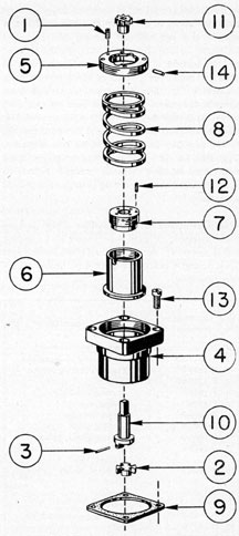
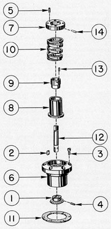
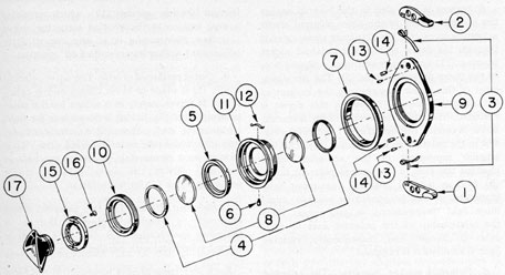
4N4. Description of the rayfilter drive packing
gland assembly. Figure 4-32 shows this packing
gland assembly. All bubble numbers in Sections
4N4, 5, and 6 refer to Figure 4-32 unless otherwise specified.
Ill. No.
Drawing Number
Num- ber Re- quired
Nomenclature
1
P-1310-39
1
Spring retainer lockscrew
2
P-1318-9
1
Female coupling section
3
P-1318-9A
1
wire
4
P-1405-1
1
Stuffing box body
5
P-1405-2
1
Spring retainer
6
P-1405-3
1
Spring cylinder
7
P-1405-4
1
Packing gland
8
P-1405-5
1
Packing gland spring
9
P-1405-6
1
Stuffing box body rubber gasket
10
P-1406-9
1
Rayfilter drive actuating shaft
11
P-1409-3
1
Rayfilter drive actuating gear
12
P-1422-7
1
Packing land lockscrew
13
P-1422-8
4
Stuffing box body lockscrews
14
P-1422-175
1
Spring retainer dowel pin
a. Stuffing box body. The stuffing box body
(4) is made of phosphor bronze and is 1.485
inches in length. It consists of a body section
undercut a distance of 0.785 inch, with a medium
shoulder section a sliding fit in the bored hole
in the eyepiece box front opening below and to
the right of the eyepiece window assembly
(27, Figure 4-29). It is provided with a large
rectangular shoulder flange with rounded corners
a sliding fit in the rectangular recess section
part of the same opening. The rectangular
flange has four countersunk clearance holes
for the insertion of lockscrews (13), and is
secured in the rectangular recess in the eyepiece
box on a rectangularly shaped gasket (9). The
lockscrews extend into nominal depth tapped
holes in the remaining rectangular recess front
wall of the eyepiece box.
The stuffing box body center axis is reamed
to accommodate the rayfilter drive actuating
shaft (10). The inside surface has three counterbored sections. One is counterbored a depth
of 1.360 inches, leaving a center section, and
providing a cylinder area for the spring cylinder
(6) and sufficient clearance for compression
of the packing gland spring (8).
The large counterbore, 0.282 inch deep, is
threaded to receive the spring retainer threaded
periphery against the shoulder seat of this
counterbored section. The center section, located
with its face a depth of 0.406 inch from the outer
face of the rectangular flange, is counterbored
a depth of 3/8 inch, having a chamfered seat of
30 degrees. This counterbored area serves as the stuffing
box chamber to receive the flax packing and
the undercut section and upper chamfered
seat of the packing gland (7). The flax packing
is compressed against the chamfered seat of
the stuffing box chamber by the opposite chamfered seat of the packing gland, thus forcing
the flax packing to adhere to the rayfilter drive
actuating shaft (10).
The stuffing box body is counterbored in the
lower part a depth of 0.484 inch to provide
sufficient clearance for the rayfilter drive actuating shaft (10) shoulder male coupling section,
the female coupling section (2), and its interconnection with the male coupling section (40,
Figure 4-28) of the eyepiece skeleton assembly.
This counterbore serves as an alignment support
section for the interconnecting coupling sections
mentioned above.
b. Rayfilter drive actuating shaft. The
rayfilter drive actuating shaft (10) is made of
corrosion-resisting steel and is 1 15/32 inches long.
The flange section of the shaft has two projecting
lugs to form a male coupling section with the
assembled female coupling section (2) which
provides interconnection with the male coupling
section (40, Figure 4-28) of the eyepiece skeleton
assembly. The main body of the shaft is a sliding
fit in the reamed hole in the stuffing box body
(4) and the reamed hole in the packing gland (7).
The flax packing surrounds the main body of the
shaft in the stuffing box chamber. The square
section of the upper part of the shaft carries a
rayfilter drive actuating gear (11).
c. Female coupling section. The female
coupling section (2) is made of corrosion
164
resisting steel and is of nominal thickness. It is
shaped cylindrical with four equally spaced slots,
and is assembled between the two opposite
projecting lugs of the male coupling flange
section of the rayfilter drive actuating shaft (10).
It is secured with a bronze wire (3) which is
inserted through a small drilled hole in the
opposite lugs and the center section remaining
between the depth of the opposite slots of this
coupling. The bronze wire is spread on opposite
sides of each male lug, allowing the female
coupling section a small axial thrust. When it
is assembled to the projecting male lugs of the rayfilter drive actuating shaft (10), it serves as
a coupling for interconnection between the male
coupling section (40, Figure 4-28) of the eyepiece
skeleton assembly, using the two opposite slots
at right angles to the assembled pinned slots.
d. Rayfilter drive actuating gear. The
rayfilter drive actuating gear (11) is made
of phosphor bronze with a square broached
hole in its center axis, and is a push fit over
the square section of the rayfilter drive actuating
shaft (10). The large diameter is provided with
16 teeth of 32 diametral pitch which mesh with
the rayfilter drive actuating gear rack (8,
Figure 4-40) of the rayfilter assembly. The hub
section of the gear is a sliding fit in the reamed
hole axis of the packing gland (7). The rayfilter
drive actuating gear (11), in mesh with the rayfilter drive actuating gear-rack (8, Figure 4-40)
of the rayfilter assembly, provides the interconnection with the eyepiece drive mechanism
located in the eyepiece skeleton assembly (Figure
4-28) to synchronize its vertical travel.
e. Packing gland spring. The packing
gland spring (8) is made of chrome silicon
manganese steel alloy and has a free length of
2 1/2 inches. The spring fits loosely over the undercut body and rests on the shoulder seat of the
spring cylinder (6). The spring when compressed, has a length of 7/8-inch at its fully
loaded position.
f. Spring retainer. The spring retainer (5)
is made of phosphor bronze ands is 9/32 inch
in width. It is cylindrical, having a threaded
periphery to screw into the large threaded
counterbored section and shoulder seat in the
stuffing box body (4). The internal surface of
the spring retainer is bored to provide sufficient
clearance for the packing gland (7). It is counterbored in the lower part and provided with
sliding clearance for the upward movement of
the spring cylinder (6) for the loading of the
packing gland (7).
A dowel pin hole is provided in the threaded
periphery for the insertion of a dowel pin (14)
of a drive fit. The dowel pin projects inward
from the counterbored wall a sufficient distance
to engage in the axial slot of the spring cylinder
upper part. Its protrusion in the axial slot serves
only to restrict the movement of the spring
cylinder when loading the packing gland, and
does not interfere with the threaded periphery
of the packing gland (7).
Two opposite radius grooves are cut in the
inner bored shoulder to a depth of the counterbored wall to provide the repairman a visual
determination of the loaded position of the
spring cylinder (6) as it contacts the shoulder
seat of the spring retainer.
Two holes are drilled in the threaded periphery
along a diameter, and the wall has a narrow slot
cut halfway through the shoulder to these drilled
holes. In the center of the slotted section, a
tapped hole is provided near the periphery for
insertion of a lockscrew (1). This lockscrew
when tightened spreads the narrower slotted
half of the wall away from the heavier part, and
secures the spring retainer in the internal
threaded counterbored section in the stuffing
box body. The face of the spring retainer is
provided with four equally spaced shallow holes
to accommodate the projecting prongs of a
special wrench. The spring retainer compresses
the packing gland spring (8) for its initial compressed length of 31/64 inch.
g. Spring cylinder. The spring cylinder
(6) is made of phosphor bronze and is 1.200
inches in length. It is bored a sliding fit over
the external shoulder surface of the stuffing
box chamber. The external surface is undercut
down to a narrow shoulder of nominal wall
thickness to carry the packing gland spring
(8) loosely in the cylinder area between the
internal and external walls of the stuffing box
body. The upper part of the spring cylinder has
165
an internal threaded section to receive, the
packing gland threaded periphery, with an
elongated slot having a depth of 0.150 inch.
This slot engages a stationary dowel pin (14)
projecting inward from the inner wall of the
spring retainer (5) to restrict the spring cylinder
(6) from turning when the packing gland is
screwed into the internal threaded section in
the spring cylinder while loading the gland.
As the packing gland (7) is screwed into the
spring cylinder (6) against the flax packing
surrounding the rayfilter drive actuating shaft
(10) in the stuffing box body chamber, the
initial compression of the packing gland spring
(8) is compressed further by the upward movement of the spring cylinder (6), thus loading
the packing gland (7). The loaded packing gland
is always under spring pressure against the flax
packing in the chamber, provided the spring
cylinder is lifted clear of cylinder area base in
the stuffing box body.
h. Packing gland. The packing gland (7)
is made of phosphor bronze and is 1/2 inch in
length. It is cylindrical with a large shoulder
having a threaded periphery to engage into the
internal threaded section of the upper part of
the spring cylinder (6).
The packing gland is provided with an undercut section a sliding fit in the counterbored
section of the stuffing box chamber. The center
axis has a reamed hole, a sliding fit on the upper
part of the rayfilter drive actuating shaft (10).
The lower internal surface of the undercut section
is provided with a 30 degrees chamfered seat to compress
the flax packing properly for its adherence
around the rayfilter drive actuating shaft.
Two holes are drilled in the threaded periphery
along a diameter, and the wall has a narrow slot
cut halfway through the shoulder to these drilled
holes. In the center of the slotted section, a
perpendicular upped hole is provided near the
periphery for the insertion of a lockscrew (12).
This lockscrew, when tightened A, spreads the
narrower slotted half of the wall away from the
heavier part and secures the packing gland in
the internal threaded section of the spring
cylinder (6). The face of the packing gland (7)
is provided with four equally spaced shallow
holes to accommodate the projecting prongs of a
special wrench.
i. Stuffing box body rubber gasket. The
stuffing box body rubber gasket (9) is made of
synthetic rubber of rectangular shape, while
the center hole is cylindrical. The rubber gasket
fits between the rectangular flange of the stuffing
box body, in the rectangular recess seat of the
eyepiece box (11, Figure 4-29). Clearance
holes are punched in the four corners to match
with the clearance holes in the rectangular flange
and the tapped holes in the rectangular recess
face of the eyepiece box base.
4N5. Disassembly of the rayfilter drive packing
gland assembly. The rayfilter drive packing
gland assembly is disassembled in the following
manner:
1. Remove the rayfilter drive actuating
gear (11), pulling it off the square section of
the rayfilter drive actuating shaft (10).
2. Remove the lockscrew (12) from the face
of the packing gland (7).
3. Using a special wrench, insert the projecting prongs of the wrench in the four shallow
holes in the packing gland face (7). Unscrew
the packing gland from the spring cylinder (6),
unloading the packing gland (7) and thus
releasing the pressure on the flax packing.
Remove the packing gland.
4. Remove the rayfilter drive actuating shaft
(10), carrying it out from the lower part of the
stuffing box body (4) with the assembled female
coupling section (2) and its securing bronze
wire (3).
5. Remove the lockscrew (1) from the spring
retainer face (5).
6. Using a special spring-unloading wrench
(Figure 4-34), run the wing nut out a sufficient
distance on the guide plug integral shaft threads.
Screw the guide plug threaded periphery into
the internal threaded section in the spring
cylinder (6). Insert the projecting prongs of the
wrench body into the four shallow holes in the
166
spring retainer face (5), and run the wing nut
down snugly on the upper part of the wrench.
7. Unscrew the spring retainer (5), carrying
with it the packing gland spring (8) and the
spring cylinder (6). The spring remains at its
initial compressed position (Figure 4-33).
Figure 4-33. Special spring-unloading and loading
wrench with spring fully loaded.
8. Unscrew the wing nut, carrying it outward
on the guide plug shaft and thus releasing the
spring tension (Figure 4-34).
9. Unscrew the spring cylinder (6) from the
guide plug and integral shaft. Remove the
spring cylinder (6), packing gland spring (8),
and spring retainer (5).
10. Remove the old flax packing, and destroy
it, leaning out the stuffing box chamber.
11. Clean all parts of this assembly in a clear
cleaning solvent.
4N6. Reassembly of the rayfilter parking, gland
assembly. The rayfilter packing gland assembly
is reassembled in the following manner:
1. Using the special spring-loading wrench
(Figure 4-34), run the wing nut out on the guide
plug integral shaft threads.
2. Hole the wrench with the wing nut down,
and place the spring retainer (5) over the guide
plug. Engage the four shallow holes in its face
on the projecting prongs of the wrench body.
3. Place the packing gland spring (8) over
the guide plug, and screw the spring cylinder (6)
on the threaded periphery of the guide plug.
4. Slowly screw the wing nut tight, observing
the dowel pin from its recessed position in the
spring retainer (5). The axial slot of the spring
cylinder should be kept in alignment with the
dowel pin (Figure 4-34) while screwing down
the wing nut and compressing the packing
gland spring (8). The wing nut is screwed down
Figure 4-34. Unloading of the packing gland spring
with the special wrench.
until the dowel pin is in contact with the bottom
of the axial slot. In this position, the spring is
fully loaded.
5. Screw the spring retainer (5) with the
assembly in its fully loaded position (Figure
4-33), into the internal threaded counterbore
of the stuffing box body (4). When the spring
retainer is tight against the counterbored
shoulder face of the stuffing box body, unscrew
the wing nut and remove the projecting prongs.
Unscrew the guide plug from the spring cylinder
(6). As the wing nut is released, the spring
releases the spring cylinder from the loaded
position, carrying it down to the initial compression position.
6. The use of the loading wrench and its
guide plug integral shaft and wing nut permits an
ease in disassembly and reassembly of the packing gland spring (8) and removes the excessive
wear of the spring retainer threaded periphery
(5) and the internal threaded section in the
stuffing box body (4). This would prevail were
any other procedure of assembly or disassembly
followed.
7. Insert and secure the lockscrew (1) in
the tapped hole of the spring retainer face
(5) locking the spring retainer in the stuffing
box body (4) threads.
167
8. Place the rayfilter drive actuating shaft
(10) with its assembled female coupling section
(2) in the reamed hole axis in the stuffing box
body (4). Carry the shaft in from the lower
counterbored section of the stuffing box body.
9. Using 1/4-inch flax packing, cut a length
of 3 1/4 inches, and insert it in the stuffing box
chamber around the rayfilter drive actuating
shaft (10).
10. Place the packing gland (7) over the shaft
and in the stuffing box chamber, and press downward, using a special wrench. Place the projecting prongs of the wrench in the four shallow
holes in the packing gland face. Engage the
packing gland threaded periphery in the internal
threads of the spring cylinder (6). Check the
entrance of the packing gland in the stuffing box
chamber to insure that there are no loose ends
of the flax packing overlapping the shoulder of
the stuffing box chamber.
11. After setting up the flax packing the first
time, repeat Steps 9 and 10 the second time.
Allow the packing to set 30 minutes before
screwing the packing gland face flush with the
face of the spring retainer (5). In this final
setting up of the packing gland, the spring
cylinder (6) should be observed by viewing its
position through the opposite radius slots of the
spring retainer (5). Note its position, as it should
be in contact with the counterbored face of the
spring retainer.
12. Insert and secure the lockscrew (12) in
the tapped hole in the packing gland face (7),
locking the packing gland in the threads of the
spring cylinder (6).
13. Place the rayfilter drive actuating gear
(11) on the square section of the rayfilter drive
actuating shaft (10). Carry the hub section of
the gear into the upper part of the reamed hole
in the packing gland (7). Check the reference
punched marks of the gear and shaft for proper
coincidence.
14. This rayfilter packing gland assembly is
pressure tested as described under Section 4N13.
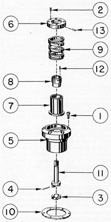
4N7. Description of the eyepiece drive packing
gland assembly. Figure 4-35 shows the eyepiece
drive packing gland assembly. All bubble numbers in Sections 4N7, 8, and 9 refer to Figure
4-35 unless otherwise specified.
Ill. No.
Drawing Number
Num- ber Re- quired
Nomenclature
1
P-1160-11
1
Eyepiece drive mechanism bevel gear
2
P-1163-11
1
Eyepiece drive mechanism bevel gear key
3
P-1179-45
6
Stuffing box body lockscrews
4
P-1179-60
1
Prism shift mechanism bevel gear lockscrew
5
P-1310-39
1
Spring retainer lockscrew
6
P-1406-2
1
Stuffing box body
7
P-1406-3
1
Spring retainer
8
P-1406-4
1
Spring cylinders
9
P-1406-5
1
Packing gland
10
P-1406-6
1
Packing gland spring
11
P-1406-7
1
Stuffing box body rubber gasket
12
P-1409-2
1
Eyepiece drive actuating shaft
13
P-1422-2
1
Packing gland lockscrew
14
P-1422-175
1
Spring retainer dowel pin
a. Stuffing box body. The stuffing box body
(6) is made of phosphor bronze and is 1.500
inches in length. It is cylindrical and consists of a
small undercut shoulder section, a medium
shoulder section, and a large shoulder flange
in the upper part. The small shoulder section is a
loose fit in the bored opening and counterbored
recess in the eyepiece box (11, Figure 4-29)
between the two air valve body assemblies.
The medium shoulder is a sliding fit in the bored
hole, while the large shoulder flange is a sliding
fit in the counterbored recess.
The outer face of the large shoulder flange is
chamfered at 30 degrees. The chamfered face projects
above the recess 6f the eyepiece box and conforms
to the contour of its periphery, setting slightly
below it. They large shoulder flange rests on a
stuffing box body rubber gasket (11) and is
secured to maintain the hermetical seal of
the stuffing box body with six lockscrews (3).
These lockscrews are inserted into countersunk
clearance holes in the large shoulder flange and
screwed into tapped holes in the counterbored
recess seat.
The stuffing box body axis is provided with
two reamed holes in the lower part to receive
168
the undercut stub section and main body section
of the eyepiece drive actuating shaft (12), a
sliding fit in both reamed holes.
The internal surfaces of the stuffing box body
are treated in comparison to the rayfilter drive
packing gland assembly stuffing box body (4,
Figure 4-32) as follows: The cylinder area for
the spring cylinder (8) and the packing gland
spring (10) is the same depth but smaller in
diameter. The center section wall is smaller in
diameter and length. The stuffing box chamber is
smaller in diameter and longer in depth, while
it has a chamfered packing gland seat of 45 degrees.
The large threaded counterbored section is
smaller in diameter and has the same depth
to receive the spring retainer (7).
b. Eyepiece drive actuating shaft. The
eyepiece drive actuating shaft (12) is made of
corrosion-resisting steel and is 1 29/32 inches long.
The stub section is provided with a recess
keyway for the insertion of a key (2). The stub
section carries the eyepiece drive mechanism
bevel gear (1) with a keyseat over this section
and is secured with a lockscrew (4). The main
body is carried a sliding fit in the large reamed
hole axis, while a portion of the stub section is
carried a sliding fit in the small reamed, hole
axis in the stuffing box body (6). The main
body section protruding through the stuffing
box chamber is surrounded by flax packing.
The square section of the outer part of the
shaft forms a connection with the square
broached hole in the female coupling section
(3) of the focusing knob assembly (Figure 4-39).
c. Eyepiece drive mechanism bevel gear.
The eyepiece drive mechanism bevel gear (1)
is made of phosphor bronze, with a reamed hole
in its center axis, and is provided with a keyseat.
The large diameter is provided with 28 bevel
teeth of 32 diametral pitch, and has a pitch
cone line angle of 60 degrees. It meshes with an identical
bevel gear called the eyepiece prism shift bevel
gear (11, Figure 4-28) of the eyepiece skeleton
assembly. The bevel gear is a push fit over the
inserted key (2) and the stub section of the
eyepiece drive actuating shaft (12). The hub
section has a tapped hole for the insertion of a
lockscrew (4) to secure the bevel gear from axial
displacement on the stub section of the shaft
(12). The bevel gear engaging with the eyepiece
prism shift bevel gear (11, Figure 4-28) of a
60 degrees pitch cone line angle, provides operation for
the eyepiece drive mechanism of the eyepiece
skeleton assembly by the rotation of the focusing
knob (1, Figure 4-39).
d. Packing gland spring. The packing
gland spring (10) is made of the same material
and thickness as the rayfilter drive packing
gland assembly packing gland spring (8, Figure
4-32) except that it is shorter in length and
169
smaller in diameter. It provides the same function and is compressed to the same fully loaded
length. It fits loosely on the undercut body and
rests on the shoulder seat of the spring cylinder
e. Spring retainer. The spring retainer (7)
is made of the same material and thickness as
the rayfilter drive packing gland assembly
spring retainer (5, Figure 4-32) except that it is
smaller in proportion to the large threaded
counterbored section of the stuffing box body
(6). It is secured in the same manner with a
lockscrew (5).
f. Spring cylinder. The spring cylinder (8)
is of the same material and length as the rayfilter drive packing gland assembly spring cylinder (6, Figure 4-32) except that the diameter
is smaller and the internal threaded section is
longer. It is designed for the same purpose and
functions.
g. Packing gland. The packing gland (9)
is made of the same material and is smaller in
diameter, having a longer threaded periphery
than its corresponding part in the rayfilter
drive packing gland assembly packing gland
(7, Figure 4-32). It is provided with a smaller
reamed hole in its center axis, for the eyepiece
drive actuating shaft (12), with the lower
internal surface of the undercut section provided
with a 45 degrees chamfered seat. The upper part is
counterbored a nominal depth to provide clearance for an external connection with the female
coupling section (3, Figure 4-39) of the focusing
knob assembly. It is secured in the spring
cylinder threaded section with a lockscrew (13)
in similar manner, and is designed for the same
purpose and functions.
4N8. Disassembly of the eyepiece drive packing
gland assembly. The eyepiece drive packing
gland assembly is disassembled in the following
manner:
1. Remove the lockscrew (4) from the hub
section of the eyepiece drive mechanism bevel
gear (1).
2. Remove the eyepiece drive mechanism
bevel gear (1), pulling it off the stub section of the
eyepiece drive actuating shaft (12) and the
inserted key (2).
3. Remove the inserted key (2) from the
stub section of the eyepiece drive actuating
shaft (12).
4. Remove the lockscrew (13) from the
packing gland face (9).
5. Remove the packing gland (9) in the
manner described under Section 4N5, Step 3.
6. Remove the eyepiece drive actuating
shaft (12), carrying it out from the large shoulder
flange end of the stuffing box body (6).
7. Remove the lockscrew (5) from the spring
retainer face (7).
8. Using a special spring-unloading wrench
of smaller design such as that used under Section
4N5, Step 6, unscrew the spring retainer (7),
carrying with it the packing gland spring (10)
and the spring cylinder (8), in similar manner to
that stated in Section 4N5, Step 7, and Figure
4-33.
9. Unscrew the spring cylinder (8) from the
guide plug and integral shaft. Remove the spring
cylinder packing gland spring (10) and the
spring retainer (7, Figure 4-34).
10. Follow the procedure outlined in Section
4N5, Steps 10 and 11.
4N9. Reassembly of the eyepiece drive packing
gland assembly. The eyepiece drive packing gland
assembly is reassembled in the following manner:
1. Using the special spring-loading wrench
of smaller design, follow the procedure described
in Section 4N6, Steps 1, 2, 3, 4, and 5, for the
reassembly of the spring retainer (7), packing
gland spring (10), and the spring cylinder (8)
in the stuffing box body (6).
2. Insert and secure the lockscrew (5) in
the tapped hole of the spring retainer face (7),
locking the spring retainer in the stuffing box
body threads (6).
170
3. Place the stub section of the eyepiece
drive actuating shaft (12) in the reamed hole
in the stuffing box body (6), placing it in from
the large shoulder flange end.
4. Using 1/8-inch flax packing, cut a length
5 inches, and insert it in the stuffing box chamber
around the eyepiece drive actuating shaft (12).
5. Place the packing gland (9) on the shaft
in the stuffing box chamber, and press downward
using a special wrench. Place the projecting
prongs of the wrench in the four shallow holes
of the packing gland face. Engage the packing
gland threaded periphery in the internal threads
in the spring cylinder (8). Follow the precautions
listed under Section 4N6, Step 10.
6. Follow Section 4N6, Step 11, for the
second length of packing and the setting up of
the packing gland (9).
7. Insert and secure the lockscrew (13)
in the tapped hole in the packing gland face (9),
locking the packing gland in the threads of the
spring cylinder (8).
8. Insert the key (2) in the stub section of
the eyepiece drive actuating shaft (12).
9. Place the eyepiece drive mechanism
bevel gear (1) over the inserted key (2) and
on the stub section of the eyepiece drive actuating shaft (12). The hub section of the gear faces
the stuffing box body lower face (6).
10. Insert and secure the lockscrew (4) in
the hub section of the bevel gear (1) and the
spotted recess in the stub section of the shaft
(12).
11. This eyepiece drive packing gland assembly is pressure tested as described under
Section 4N13.
4N10. Description of the left and right training
handle packing gland assemblies. The left end right
training handle packing gland assemblies are
identical. Figure 4-36 shows this assembly. All
bubble numbers in Sections 4N10, 11, and 12
refer to Figure 4-36 unless otherwise specified.
Ill. No.
Drawing Number
Num- ber Re- quired
Nomenclature
1
P-1179-45
12
Stuffing box body lockscrews
2
P-1310-39
2
Spring retainer lockscrews
3
P-1318-2
2
Female coupling sections
4
P-1318-2A
2
Wires
5
P-1406-1
2
Stuffing boxes bodies (L&R)
6
P-1406-3
2
Spring retainers
7
P-1406-4
2
Spring cylinders
8
P-1406-5
2
Packing glands
9
P-1406-6
2
Packing gland springs
10
P-1406-7
2
Stuffing box body rubber gaskets
11
P-1406-8
2
Actuating shafts (L&R)
12
P-1422-2
2
Packing gland lockscrews
13
P-1422-175
2
Spring retainer dowel pins
a. Stuffing box body. The stuffing box
body (5) corresponds to the eyepiece drive
packing gland assembly stuffing box body (6,
Figure 4-35) except that it has a single axis
reamed hole, and a chamfered lower end. This
reamed hole carries the actuating shaft (11).
The stuffing box body fits on either side of the
eyepiece box (11, Figure 4-29) in a bored hole
and countersunk recess seat on a stuffing box
body rubber gasket (10). This rubber gasket
maintains the hermetical seal of the stuffing box
body when secured with six lockscrews (1).
These lockscrews are inserted into countersunk
clearance holes in the stuffing box large shoulder
flange and screwed into tapped holes in the
counterbored recess seat in the eyepiece box
(11, Figure 4-29).
b. Actuating shaft. The actuating shaft
(11) is almost identical to the rayfilter drive
actuating shaft (10, Figure 4-32) except in
diameter and length. The square section is larger
in diameter and length. The main body is
smaller in diameter and longer. The flange
sections of the shafts with two projecting
lugs forming the male coupling section are
identical. When assembled with the female
coupling section (3), it provides interconnection
with the male coupling section of the training
handle rack gear and integral shaft (39, Figure
4-28) in either side of the eyepiece skeleton
assembly. The square section of the shaft engages into the square broached hole in the inner
bevel gear clutches (14 and 16, Figures 4-43 and
171
4-44 respectively) of the left and right training
handle assemblies.
c. Female coupling section. The female
coupling section (3) is almost identical to the
female coupling section (2, Figure 4-32) of the
Figure 4-36. Left and right training handle packing
gland assemblies.
rayfilter drive Backing gland assembly, with an
exception in the outer diameter The coupling
section is assembled with a bronze wire (4) in
the same manner.
d. Packing gland spring. The packing
gland spring (9) is identical to the packing
gland spring (10, Figure 4-35) of the eyepiece
drive packing gland assembly.
e. Spring retainer. The spring retainer
(6) is identical to the spring retainer (7, Figure
4-35) of the eyepiece drive packing gland
assembly, and is locked in the stuffing box body
(5) in the same manner with a lockscrew (2).
f. Spring cylinder. The spring cylinder (7)
is identical to the spring cylinder (8, Figure
4-35) of the eyepiece drive packing gland
assembly.
g. Packing gland. The packing gland (8)
is identical to the packing gland (9, Figure 4-35)
of the eyepiece drive packing gland assembly.
The counterbore receives the inner bevel gear
clutches (14 or 16, Figures 4-43 and 4-44 respectively) of the left and fight training handle
assemblies. It is secured in the spring cylinder
(7) with a lockscrew (12) in the same manner.
4N11. Disassembly of the left or right training
handle packing gland assembly. The left or right
training handle packing gland assembly is disassembled in the following manner:
1. Remove the lockscrew (12) from the
packing gland (8).
2. Remove the packing gland (8) in the
manner described under Section 4N5, Step 3.
3. Remove the actuating shaft (11), carrying
it out from the lower part of the stuffing box
body (5).
4. Remove the lockscrew (2) from the spring
retainer face (6).
5. Follow Section 4N8, Step 7, and Section
4N5, for the removal of the spring retainer
(6), packing gland spring (9), and spring cylinder
(7).
6. Unscrew the spring cylinder (7) carrying
with it the packing gland spring (9) and the
spring retainer (6). The spring remains in the
initial loaded position (Figure 4-33).
7. Follow Section 4N5, Steps 10 and 11; see
Figure 4-34.
172
4N12. Reassembly of the left or right training
handle packing gland assembly. The left or right
training handle packing gland assembly is
reassembled in the following manner:
1. Follow the procedure stated in Section
4N9, Step 1, and Section 4N6, Steps 1, 2, 3, 4,
and 5 for reassembly of the spring retainer (6),
packing gland spring (9), and the spring cylinder
(7) in the stuffing box, body (5) see Figures
4-33 and 4-34.
2. Insert and secure the lockscrew (2) in
the tapped hole in the spring retainer face (6),
locking the spring retainer in the stuffing box
body (5).
3. Place the training handle actuating shaft
(11) in the reamed hole axis of the stuffing box
body (5), carrying it in from the lower end.
4. Follow the procedure outlined in Section
4N9, Steps 4, 5, and 6 for insertion of the flax
packing and the reassembly of the packing
gland (8) on the actuating shaft (11) and its
engagement in the spring cylinder (7).
5. Insert and secure the lockscrew (12) in
the tapped hole in the packing gland face (8),
locking the packing gland in the threads of the
spring cylinder (7).
6. The left and right training handle packing
gland assemblies are pressure tested as described
under Section 4N13.
4N13. Care of packing gland assemblies.a. General. During any general overhaul all packing
gland assemblies on the instrument should
be tightened, repacked if necessary, and pressure tested. All packing gland assemblies except
the stadimeter transmission shaft packing gland
assembly (Figures 4-30 and 4-31) can be removed
with the operating shaft in place in the gland.
If repacking is necessary, it is advisable to
disassemble the packing gland assembly to clean
out worn particles of packing and to insure free
spring action. This is done by removing the
packing gland and the spring retainer. The
spring retainer should be removed with care, as
the spring is powerful and may cause injury or
damage if suddenly freed.
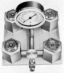
Before being reassembled to the eyepiece
box (11, Figure 4-29), packing gland assemblies
of this type should be tested individually in a
fixture (Figure 4-37) prepared for this purpose,
using 100 psi air pressure. The glands are immersed in water. No leaks should be discernible
in a half-hour test. The stadimeter transmission
shaft packing gland assembly (Figure 4-30 or
4-31) can be tested upon completion of reassembly, at which time an internal pressure
test, using nitrogen at 100 psi, should be made.
The test should be made with the periscope
completely immersed in water and all glands,
joints, and windows should be minutely examined for leaks.
b. Pressure test of the four springloaded type packing gland assemblies.
The four spring-loaded type packing gland
assemblies are pressure tested as follows:
1. Place each stuffing box body (4, 6, and 5,
Figures 4-32, 4-35, and 4-36 respectively),
and their respective stuffing box rubber gaskets
(9, 11, and 10) in the bored hole and rectangular
or counterbored recess seats in the pressure
testing fixture (Figure 4-37).
2. Secure the four packing gland assemblies
with lockscrews (13, 3, and 1, Figures 4-32,
4-35, and 4-36 respectively) to their respective
rubber gasket and seat.
3. Use 100-psi air pressure, immersing the
fixture in water. Each actuating shaft of each
individual packing gland assembly must be
rotated several times during the half-hour
test. No leaks should be discernible during
this test.
4. Upon completion of a satisfactory pressure
test, remove each of the four packing gland
assemblies from the pressure testing fixture, and
blow off all water, drying them with air.
5. Place the packing gland assemblies to one
side until ready for their reassembly to the
eyepiece box (11, Figure 4-29).
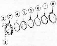
O. EYEPIECE WINDOW ASSEMBLY
4O1. Description of the eyepiece window assembly. The eyepiece window assembly consists
of the various parts to permit efficient and
comfortable use by the observer of any combination of the rayfilter and eye blinder attachments.
Figure 4-38 shows the eyepiece window assembly.
Figure 4-38. Eyepiece window assembly.
All bubble numbers in Sections 4O1, 2, and 3
refer to Figure 4-38 unless otherwise specified.
Ill. No.
Drawing Number
Num- ber Re- quired
Nomenclature
1
P-1171-7
1
Clamp ring
2
P-1179-66A
4
Frame lockscrews (short)
3
P-1179-66B
8
Frame lockscrews (long)
4
P-1179-102
1
Bezel rubber gasket
5
P-1179-103
1
Clamp ring rubber gasket
6
P-1179-120
1
Metal protection washer
7
P-1408-1
1
Frame
8
P-1408-5
1
Frame rubber gasket
9
P-1418-15
1
Eyepiece window
a. Eyepiece window. The eyepiece window
(9) consists of one crown element with parallel
surfaces, and has sufficient thickness to withstand
an internal pressure test. It is cylindrical,
and provides a means of sealing without obstruction to the emerging light rays, and offers a
transparent medium through which light can be
transmitted. The front surface is beveled at a
45 degrees angle, thus insuring the hermetical seal
between the bezel seat of the frame (7) and the
eyepiece window with a rubber gasket (4)
at the above beveled surface,
b. Frame. The frame (7) is made of cast
phosphor bronze and is 0.843 inch in width.
It is of such construction as to withstand an
internal pressure test of 300 psi. The outer
part above the recess groove section has a
rectangular projection section with narrow
flat sides serving as flanges and it projects
outward from the eyepiece box (11, Figure
4-29) when assembled. Each side flange has a.
shallow recess groove section for clearance to
carry two rayfilter plate straps (3, Figure 4-40)
when assembled in the shallow recess groove
sections which have sufficient sliding clearance.
The frame has a large cylindrical shoulder
flange, with its outer face flush with the shallow
recess groove sections. The large cylindrical
shoulder flange has four equally spaced countersunk clearance holes, while the rectangular flange
has eight countersunk clearance holes. The large
cylindrical shoulder flange is a sliding fit in the
counterbored recess seat in the eyepiece window
assembly opening of the eyepiece box (11, Figure
4-29) and rests on this counterbored recess seat
above a frame rubber gasket (8). It is secured
with four short and eight long lockscrews (2
and 3) which extend into tapped holes in the
counterbored recess seat.
The lower part of the frame below the large
cylindrical shoulder flange is undercut, and
serves as an alignment support section. It is a
174
sliding fit in the bored hole in the front of the
eyepiece box and it also provides the necessary
wall to carry the internal clamping arrangement
for the eyepiece window (9).
The inner surface of the frame is bored to
provide a clear aperture to the emerging light
rays, for all positions of plus and minus diopter
settings. Two counterbores are provided with a
45 degrees beveled seat section. The beveled seat
section serves as a bezel shoulder, and has a
bezel rubber gasket (4) adhering to it with
the tightened eyepiece window (9). The small
counterbore provides clearance for the eyepiece
window periphery, while the large counterbore
is threaded to receive the eyepiece window clamp
ring (1).
c. Metal protection washer. The metal
protection washer (6) is a thin brass washer
with nominal wall thickness. This washer is
cylindrical, and offers a smooth face for the
contact of the clamp ring (1) as it is screwed
in to tighten the rubber gasket (5) which is
located on the inner surface of the eyepiece
window (9). The metal washer is placed between
the clamp ring rubber gasket (5) and the clamp
ring (1), and protects the clamp ring rubber
gasket (5) from being disrupted when tightening
the eyepiece window with the clamp ring to
maintain the hermetical seal.
d. Clamp ring. The clamp rings (1) is made
of brass tubing and is 0.285 inch in width.
It is cylindrical and has a nominal wall thickness. The periphery is threaded to engage in
the internal threaded section in the large counterbore of the frame (7). The internal wall is
tapered, and is of nominal thickness to permit
sufficient tension for sealing the eyepiece window
(9). The narrow face has two opposite slots 180 degrees
apart, to permit clamping, removal, and reassembly of the eyepiece window by means of
a special wrench.
4O2. Disassembly of the eyepiece window assembly. The eyepiece window assembly is disassembled in the following manner:
1. Use a special wrench in the two opposite
slots in the bottom face of the clamp ring (1).
Unscrew the clamp ring from the frame (7).
2. Place a piece of lens tissue on the front
face of the eyepiece window (9) with the alignment
support section of the frame resting on its
lower face. Press downward evenly on the lens
tissue and eyepiece window to break the sticking
contact of the eyepiece window (9) and the
bezel rubber gasket (4). The loosened eyepiece
window (9) allows the clamp ring rubber gasket
(5) and the metal protection washer (6) to be
removed with it.
3. The bezel rubber gasket (4) adheres to the
bezel shoulder of the frame (7). This connection
must be broken.
4O3. Reassembly of the eyepiece window assembly. The eyepiece window assembly is reassembled in the following manner:
1. Turn the rectangular section of the frame
(7) so that it is lying on its outer face.
2. Clean the eyepiece window in similar
manner to that prescribed for the lenses of
the various other assemblies.
3. Place the new bezel rubber gasket (4)
on the bezel shoulder seat in the frame (7).
4. Place the new clamp ring rubber gasket
(5) on the inner face of the eyepiece window (9).
5. Place the metal protection washer (6)
on the clamp ring rubber gasket (5).
6. Screw the clamp ring (1) in the internal
threaded section in the frame (7). Use a special
wrench to tighten the eyepiece window (9)
sufficiently to compress both the bezel rubber
gasket (4) and the clamp ring rubber gasket (5).
The eyepiece window should not be tightened to
such an extent as to cause any strain in the glass.
Any strain causes the eyepiece window to crack
in time, necessitating renewal.
7. Place the eyepiece window assembly in a
special pressure testing jig, with the frame rubber
gasket (8) assemble in the counterbored recess
seat in the jig. Secure the frame with four short
and eight long lockscrews (2 and 3).
8. A pressure test of 100 psi under water for
30 minutes insures the hermetical seal of the
eyepiece window (9).
9. After a successful pressure test, remove the
four short and eight long lockscrews (2 and 3)
and remove the assembly and the frame rubber
gasket (8). Place aside the assembly with its lockscrews until ready for reassembly in the eyepiece
box (11, Figure 4-29).
175
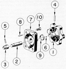
P. FOCUSING KNOB ASSEMBLY
4P1. Description of the focusing knob assembly.a. Location. The focusing knob assembly is
attached to the external recess of the eyepiece
box (11). It is located on the right-hand side
of the periscope below the hoisting yoke in such
position as to be within easy reach of the right
Figure 4-39. Focusing knob assembly.
hand of the observer. Figure 4-29 shows the
focusing knob assembly. All bubble numbers in
Sections 4P1, 2 and 3 refer to Figure 4-39
unless otherwise specified.
Ill. No.
Drawing Number
Num- ber Re- quired
Nomenclature
1
P-1133-1
1
Knob
2
P-1133-7
1
Knob shaft
3
P-1133-8
1
Female coupling section
4
P-1179-194
1
Knob and shaft taper pin
5
P-1179-195
1
Knob shaft and female coupling dowel pin
6
P-1310-39
1
Diopter ring lockscrew
7
P-1408-2
1
Knob bracket
8
P-1408-2A
2
Knob bracket dowel pins
9
P-1408-6
1
Diopter ring
10
P-1422-9
4
Knob bracket lockscrews
b. Knob. The knob (1) is made of phosphor
bronze and is 1 13/32 inches long. It is of sufficient
diameter to permit easy operation of the focusing
mechanism by hand. The periphery is scalloped.
It is filleted from the scalloped depth, and tapers
down to a hub section. The hub section is
undercut to carry a graduated diopter ring (9)
secured with a lockscrew (6). The axis is provided with a reamed hole of appropriate depth
to receive the long section of the shaft (2), and is
secured to the shaft with a taper pin (4) after
assembly.
c. Knob shaft. The knob shaft (2) is made
of monel metal and is 1 7/8 inches in length.
It forms a connection between the knob at one
part and a female coupling section (3) at the
other. The long section of the shaft carries the
knob secured with a taper pin (4). The stub
section of the shaft is undercut to carry the large
hub section of the female coupling section (3)
which is secured with a straight pin (5). When
assembled, the shaft provides a rigid support for
the knob between the female coupling section
(3) and the reamed hole in the knob bracket (7)
for manipulation of the focusing mechanism.
d. Female coupling section. The female
coupling section (3) is made of bronze rod and
is 3/4 inch in length. It consists of a large hub
section and an undercut alignment support
section. The hub section is provided with a
reamed hole of sufficient depth to retain it to
the knob shaft with a straight pin (5). The
alignment support section has a square broached
hole and is a sliding fit on the square section of
the eyepiece drive actuating shaft (12, Figure
4-35) of the eyepiece drive packing gland
assembly. The alignment support section is a
sliding fit into the counterbored recess in the
packing gland (9) of the same assembly. It
fits simultaneously over the square section of
the shaft and in the packing gland counter
bored recess.
e. Knob bracket. The knob bracket (7)
is made of cast phosphor bronze and is rectangular. It provides a rigid joint for interconnection between the eyepiece drive packing
assembly and the female coupling section (3).
The outer surface is filleted from the base of
the knob bracket to the hub section. The base
is counterbored with a 30 degrees chamfered section,
extending from the small counterbore to the
176
large, to allow clearance over the protruding
part of the assembled eyepiece drive packing
gland assembly stuffing box body (6, Figure
4-35).
The axis is provided with a reamed hole and
counterbored section, with the reamed hole
serving as a bearing, and the counterbored
section allowing clearance for the large hub
of the female coupling section (3). The two
dowel pins (8) maintain the alignment of the
knob bracket to the milled recess in the eyepiece
box. The bracket is secured with four lockscrews
(10). The lockscrews (10) are inserted into
countersunk clearance holes in the rectangular
bracket base wall and screwed in tapped holes
in the eyepiece box (11, Figure 4-29).
f. Diopter ring. The diopter ring (9) is
made of brass material and is cylindrical.
It has a nominal width and wall thickness, and
is a sliding fit on the turned shoulder of the knob
section. The outer circumference is graduated
from 0 to 3 minus and 0 to 1.5 plus diopters.
The graduated lines are spaced equally for each
diopter line, having a plus and minus engraved
indication above and below the zero diopter
line. The diopter ring is a visual indication of
the diopter reading, as the eyepiece lens is
focused, and is observed from its coincidence
with the stationary zero reference line in the
knob bracket (7). The diopter ring is set to
zero diopter and is secured with a lockscrew
(6) at the factory, after the periscope is charged
with nitrogen at 7 1/2 psi, with the use of an auxiliary telescope:
4P2. Disassembly of the focusing knob assembly.
The focusing knob assembly is disassembled in
the following manner:
1. Remove the taper pin (4) from the knob
(1) and the knob shaft (2).
2. Remove the knob (1) sliding it off the
knob shaft (2).
3. Remove the lockscrew (6) from the diopter
ring (9) and the shoulder spot face of the knob
(1). Remove the diopter ring (9) from the
knob (1).
4. Remove the knob bracket (7) from the
long section of the knob shaft (2).
5. The straight pin (5) is not removed from
the female coupling section (3) and the knob
shaft (2) as it is riveted at assembly.
4P3. Reassembly of the focusing knob assembly.
The focusing knob assembly is reassembled
in the following manner.
1. Slide the large hub section of the female
coupling section (3) on the stub section of
the knob shaft (2). Check the straight pin holes
of both for proper alignment.
2. Insert and secure the straight pin (5)
in the lined up holes, securing the female
coupling section (3) to the stub section of the
knob shaft (2) and riveting the straight pin
at assembly. (Steps 1 and 2 are included for
information, as these pieces normally are not
disassembled.)
3. Place the knob bracket (7) over the long
section of the knob shaft (2). The counterbored
section slides over the large hub section of the
assembled female coupling section (3).
4. Place the diopter ring (9) on the turned
shoulder of the knob bracket hub section (7).
Check the graduations; the minus graduations
should be located in the lower part, using
the stationary reference line of the knob bracket.
Rotate the diopter ring, to ascertain that the
tapped hole lines up with the spot face in the
turned shoulder of the knob (1), and insert and
secure the lockscrew (6).
5. Place the knob (1) on the outer part of the
knob shaft (2). Insert and secure the taper
pin (4) in the lined up holes of the knob and
the knob shaft.
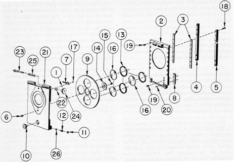
Q. RAYFILTER ASSEMBLY
4Q1. Description of the rayfilter assembly.a.
Location. The rayfilter assembly is attached
to the eyepiece window section of the periscope,
and is of such design that it does not restrict
the field of the periscope to the observer. It
is mounted external to the hermetically sealed
part of the periscope and comprises various
parts to permit the operator free and unobstructed access to the eyepiece window (9).
Figure 4-40 shows the rayfilter assembly. All
bubble numbers in Sections 4Q1, 2, and 3 refer to
Figure 4-40 unless otherwise specified.
177
Ill. No.
Drawing Number
Num- ber Re- quired
Nomenclature
1
P-1389-4
2
Spring actuated plunger knob lockscrews
2
P-1411-2
1
Rayfilter plate
3
P-1411-3
2
Rayfilter plate straps
4
P-1412-1
1
Left side bar
5
P-1412-2
1
Right side bar
6
P-1412-5
2
Anchor screw pins
7
P-1412-6
1
Detent catch spring
8
P-1412-7
1
Rayfilter drive actuating gear rack
9
P-1413-1
1
Housing disk
10
P-1413-2
1
Housing knob
11
P-1413-3
2
Friction catch spring retainers
12
P-1413-4
2
Friction catch springs
13
P-1413-5
3
Rayfilter clamp rings
14
P-1413-6
1
Housing disk shoulder washer
15
P-1413-7
1
Housing disk shoulder washer lockscrew
16
P-1418-16
3
Red, green, and yellow rayfilters
17
P-1422-4
2
Detent catch spring lockscrews
18
P-1422-5
10
Housing side bar lockscrews
19
P-1422-6
18
Rayfilter plate strap and rayfilter gear rack lockscrews
20
P-1422-176
2
Rayfilter drive actuating gear rack dowel pins
21
P-1438-1
1
Rayfilter housing
22
P-1438-2
2
Plunger rod spring bushings
23
P-1438-3
2
Spring-actuated plunger rods
24
P-1438-4
2
Spring actuated plunger knobs
25
P-1438-5
2
Plunger rod springs
26
P-1448-2
2
Ball bearing friction catches
b. Rayfilter plate. The rayfilter plate (2)
is made of cast phosphor bronze and is rectangular. This plate serves as a foundation
for the remaining parts of the assembly. The
upper part is provided with a center male
hinge projection section with a reamed hole in
its axis to accommodate two spring actuated
plunger rods (23) of the two female hinge
projection sections of the rayfilter housing (21).
The upper main inside section has a cast recess
allowing a nominal main body thickness, with
side shoulders and a narrow upper shoulder.
The side shoulders are provided with recesses
to carry the rayfilter plate straps (3) on each
side. Each rayfilter plate strap is secured to the
rayfilter plate (2) with seven lockscrews (19).
The lower section has a cast inside recess with
nominal body thickness with wider side shoulders
and a narrow lower shoulder. The side shoulders
allow the rayfilter plate a vertical movement of
1 inch and serve as stops. The left side, when
viewed from the rear of the inside recess of the
lower section, is provided with a rectangular
raised boss section or a rayfilter drive actuating
gear rack (8) secured with four lockscrews
(19) and maintained in alignment with two dowel
pins (20). This gear rack meshes with a rayfilter
drive actuating gear (11, Figure 4-32), projecting
externally from the rayfilter drive packing
gland assembly. The rayfilter drive actuating
gear (11) is synchronized to carry the rayfilter
plate (2) vertically with the eyepiece drive
mechanism of the eyepiece skeleton assembly
(Figure 4-28) for the focusing movement of
1 1/2 plus and 3 minus diopters.
The exteriors of the side shoulders of the
lower section are stepped with two spotted
recesses in the center of each step. The spotted
recesses of 120 degrees engage the ball bearing friction
catches (26) to retain the lower swinging part of
the rayfilter housing (21). Two rectangular
projecting bosses on the lower part serve as
stops to engage in slots in the lower part of the
inner, wall of the rayfilter housing (21) as the
ball bearing friction catches (26) engage in
the spotted recesses.
The main body wall is provided with a 3-inch
opening which has anti-reflection threads in
the inner circumference. This opening permits
free access to the field of the periscope for the observer. The inside recess of the main body
is provided with sliding vertical clearance
over the flat flanges of the eyepiece window frame
(7, Figure 4-38).
c. Rayfilter plate straps. The two rayfilter
plate straps (3) are made of brass and are
4.624 inches in length, having a nominal thickness and width. Each strap fits in a recess in
each side shoulder of the rayfilter plate (2),
and is secured to each recess with seven lockscrews (19). These lockscrews are inserted into
countersunk clearance holes in the rayfilter
plate (2) and screwed into tapped holes in each
strap. The outer side of each strap is flush with
178
Figure 4-40. Rayfilter assembly.
the side shoulders of the rayfilter plate (2),
while the inward protruding part fits under the
side flanges and in the shallow recess groove
section in the eyepiece window frame (7, Figure,
4-38).
d. Rayfilter housing. The rayfilter housing
(21) is made of cast phosphor bronze, and is
rectangular. This housing serves as an apron
foundation which can be removed, readily
during the installation and removal of the
periscope. It carries the rayfilter parts.
The upper part is provided with two female
hinge projection sections, a sliding fit over the
center male hinge projection section of the rayfilter plate (2). Both hinge projection sections
are reamed in their axis to carry the spring-actuated plunger rods (23) which are moved
axially against spring tension for removal or
reassembly to the center male hinge projection
of the rayfilter plate. Both female hinge projection sections have a threaded section located at
each outer end to carry two plunger rod spring
bushings (22).
The inside section has cast recesses allowing
a nominal main body thickness, with a shallow
shoulder wall bordering its rectangular body.
A cylindrical raised boss below the bored opening is provided to carry the housing disk bored
axis hole (9). The side shoulders are counterbored, concentric with the cylindrical raised
boss to provide clearance for the protruding
periphery of the housing disk (9).
The cylindrical raised boss has a tapped
hole in its center axis and a shallow counterbored
section. The counterbored section carries the
housing disk shoulder washer (14), while the
tapped hole receives a lockscrew (15) to secure
the shoulder washer.
The lower part of the inner section has two
rectangular shoulder projections on both sides,
in the center of which two ball bearing friction
catches are provided. These two shoulder
projections are a sliding fit over the shoulder
steps of the rayfilter plate (2). The center of
each projection is provided with a 90 degrees spotted
recess and a tapped section with a smaller
179
clearance hole. The ball bearing friction catches
(26) fit into the clearance hole and spotted
recess to project about 1/32 inch. A friction catch
spring (12) fits loosely in the clearance hole,
and is compressed against the ball bearing
friction catches (26) by the friction catch spring
retainer (11). The spring retainer is screwed
into the tapped hole in the projection and
compresses the spring (12) to hold the ball bearing snugly in the 90 degrees spotted recess.
When the rayfilter housing (21) is swung
to the closed position, the ball bearing friction
catches (26) engage in the 120 degree spotted recesses
in each shoulder stop of the rayfilter plate (2),
thus retaining the rayfilter housing (21) in the
closed position. The rectangular stops of the
rayfilter plate (2) are also in contact in the milled
slots in the rayfilter housing (21).
The upper right side of the inner main body
is provided with a raised rectangular boss,
on which a detent catch spring (7) is mounted
and secured with two lockscrews (17). This
detent catch spring engages into the V-groove
notch of the housing disk periphery, thus
retaining it in any of the four positions desired.
The side shoulders above the two lower
rectangular projections are provided with a
left and right side bar (4 and 5) on the inner
face of the rayfilter housing (21). These side
bars are secured with five lockscrews (18) which
are inserted in countersunk clearance holes
in the side bars and screwed into tapped holes
in the rayfilter housing sides shoulders. These
side bars prevent foreign matter from being
carried into the inner assembly of the rayfilter
housing (21).
The outer face of the main body is provided
with a large, flat, raised boss which has a bored
hole and shallow counterfaced section. The bored
hole is provided for light transmission and has
anti-reflection threads on its inner circumference.
The base of the eye blinder assembly and the
variable density polaroid filter assembly is
centered in this shallow counterfaced recess,
and rests on the large flat raised boss. Either
of the two assemblies is retained by two anchor
screw pins (6), located with an appropriate
center distance concentric with the bored hole
and counterfaced shallow recess.
In the lower central part of the outer face
of the main body wall, a raised boss is provided
with a reamed hole. The inside face of the
reamed hole in the boss is countersunk, to allow
sufficient space for peening of the pressed-in
stub shaft of the housing knob (10). The housing
knob furnishes the observer a provision by
which he can pull the lower swinging part of the
rayfilter housing (21) free of its friction catch
engagement with the rayfilter plate (2).
e. Housing disk. The housing disk (9) is
made of cast phosphor bronze and is cylindrical.
It has a diameter of 5.200 inches, with the
periphery rough parallel knurled, and is provided with four equally spaced 90 degrees V-groove
notches to engage a detent catch spring (7).
The housing disk axis is bored a sliding fit over
the cylindrical raised boss of the inner body
wall of the rayfilter housing (21). It has a
shallow counterbored section to receive a
shoulder washer (14) which is secured with a
lockscrew (15). The inner face of the housing
disk has a narrow projecting shoulder of 0.016
inch. This narrow shoulder contacts the inner
body wall of the rayfilter housing (21, allowing
the remaining wall of the housing disk clearance
over the rayfilter housing inner body wall.
Four equally spaced bored holes and threaded
counterbored sections are provided in the same
centerlines with the four periphery V-groove
notches, for the insertion of red, green, and
yellow rayfilters (16). The rayfilters rest on the
counterbored seat in the counterbore of the
clamp rings (13). The fourth opening remains
clear.
f. Rayfilters. The three rayfilters (16) consist simply of cylindrical, colored filter glass
with parallel surfaces. Three shades are used red, green, and yellow. These are provided for
various conditions of observation. Each rayfilter
is mounted in the counterbore of the clamp
ring (13) and rests against the narrow shoulder
seat of each threaded counterbored section in the
housing disk (9).
g. Clamp rings. The three clamp rings (13)
are made of seamless brass tubing, having a
bored hole and counterbored section provision.
The periphery is threaded and engages in the
threaded counterbored section of any of the four
180
openings of the housing disk. The counterbored
recess is a sliding fit over the periphery of
the rayfilter, securing it to the narrow shoulder
seat of the housing disk (9). The inner wall of the
clamp ring is chamfered at 20 degrees from the bore
in its outer face. The outer face of each clamp
ring is provided with opposite slots of shallow
depth for the insertion of a special wrench.
h. Shoulder washer. The shoulder washer
(14) is made of rolled bronze and is cylindrical.
The large diameter is a sliding fit in the counterbored section in the housing disk axis while
the small shoulder is a sliding fit in the counterbored section in the raised boss on the inner
body wall of the rayfilter housing (21). The small
shoulder rests in the counterbored section seat
in the raised boss, offering a nominal clearance
to the housing disk (9). It is secured with a
lockscrew (15) which is inserted in a countersunk clearance hole in the shoulder washer (14)
and screwed into the tapped hole axis in the
cylindrical raised boss.
i. Detent catch spring. The detent catch
spring (7) is made of phosphor-bronze sheet
and tempered. It has a developed length of 1.440
inches with a large rectangular section with
two clearance holes as its securing part. This
section is bent at 90 degrees and is secured to the raised
rectangular boss section in the upper right side
of the inner body wall of the rayfilter housing
with two lockscrews (17). The projecting arm
of this detent catch spring is provided with a
90 degrees detent bend conforming to the four 90 degrees
V-groove notches in the housing disk periphery.
The 90 degrees detent bend has a protruding depth
of 0.093 inch, and when secured in the 90 degrees
V-groove notch of the housing disk periphery,
it holds the housing disk in the centerline under
its spring tension.
j. Anchor screw pins. The two anchor
screw pins (6) are made of corrosion-resisting
steel and are 0.516 inch in length. The lower
threaded part engages in the tapped holes in
the flat raised boss section and main Wall of the
rayfilter housing (21), up to its lower narrow
shoulder and is soldered at assembly. The undercut section permits locking of the finger grip
levers of the eye blinder assembly (Figure 4-42)
and the variable density polaroid assembly (Figure 4-41).
The finger grip levers of these assemblies,
by means of tension springs, force them into the
undercut sections of the anchor screw pins,
thus retaining each assembly to the rayfilter
housing (21). The upper and lower shoulders
next to the undercut section are chamfered to
allow for rapid removal of the finger grip levers
of either assembly. The upper face has a radius
to allow centering and ease of entry in the holes
in the base plate of either assembly and the finger
grip levers.
k. Spring-actuated plunger rods. The
two spring-actuated plunger rods (23) are made
of corrosion-resisting steel material. The stub
section is a sliding fit in the reamed hole located
in the center male hinge projection section of the
rayfilter plate (2). The stub section of each
spring-actuated plunger rod assembled in each
side of the female hinge projection sections of
the rayfilter housing (21) form the hinge pins,
to allow the rayfilter housing to swing upward
when the lower part of the rayfilter housing is
pulled clear of its engagement in the friction
catch spotted recesses.
The shoulder section of the plunger rod slides
axially in the reamed hole in each female hinge
projection section against the spring tension,
when pulled outward by the assembled plunger
knobs. The plunger knobs are pulled outward
only when removing or replacing the rayfilter
housing (21).
The stem section of the plunger rods slides
through each reamed hole in the plunger rod
spring bushings (22), with the outer part of the
stem section threaded to carry a plunger knob
(24). The main body is slightly larger than the
stem section in order to serve as a stop and to
restrict the outward thrust of the plunger rod.
A compression spring (25) fits over the main body
up to the shoulder section, and is retained in
the reamed hole in each female hinge projection
section with a threaded plunger rod spring
bushing (22).
l. Plunger rod spring bushings. The two
plunger rod spring bushings (22) are made of
phosphor bronze, The periphery is threaded to
engage into tapped holes in the outer part of
the female hinge projection sections of the
rayfilter housing (21). The plunger bushings
181
serve as a spring retainer and plunger release
stop; the reamed axis hole serves as an alignment guide for the stem section of the plunger
rod. Two opposite slots are provided in the
outer face for the insertion of a screwdriver
blade.
m. Spring-actuated plunger knobs. The
two spring-actuated plunger knobs (24) are
made of phosphor bronze and are chromium
plated. The periphery of each knob is fine
diamond knurled to provide a firm finger grip.
The center axis has a tapped hole to engage on
the threaded part of the plunger rod stem
section. The contour of the external surface is
similar to an ordinary knob, with a hub section
provided with a tapped hole to receive a lockscrew (1), thus securing the knob to the plunger
rod. The knob offers the observer a firm grip
projection and serves as a stop when the rayfilter housing (21) is removed.
4Q2. Disassembly of the rayfilter assembly. The
rayfilter assembly is disassembled in the following manner:
1. Lift the lower swinging part of the rayfilter
housing (21) by grasping the housing knob (10)
and pulling it clear of its engagement in the
friction catch spotted recesses of the rayfilter
plate (2).
2. Grasp the two spring-actuated plunger
knobs (24) pulling them outward as far as
possible, thus removing the rayfilter housing (21)
from the rayfilter plate (2).
3. Remove the rayfilter plate (2) by removing
the seven lockscrews (19) and the rayfilter
plate straps (3) from each side. This simulates
the removal of the rayfilter plate from the
eyepiece window frame (7, Figure 4-38).
4. Remove the five lockscrews (18) from the
left and right side bars (4 and 5), and remove the
side bars from the rear shoulders of the rayfilter
housing (21).
5. Remove the lockscrews (15) from the
housing disk shoulder washer (14).
6. Remove the housing disk (9), lifting it
away from the rayfilter housing (21), carrying
the shoulder washer (14) with it. Remove
the shoulder washer (14) from the housing
disk (9).
7. Using an adjustable wrench, unscrew
the clamp rings (13) from the housing disk (9).
Remove the clamp rings and the red, green, and
yellow rayfilters (16), in the order named. Wrap
the filters in lens tissue and place to one side
to prevent scratches and breakage.
8. Remove the two lockscrews (1), unscrewing them from the hubs of the spring-actuated.
plunger knobs (24).
9. Wrap a piece of emery cloth around the
extended part of each spring-actuated plunger
rod (23). Holding the emery cloth and rod firmly
with a pair of parallel pliers, unscrew each
spring-actuated plunger knob (24) from the
threaded part of the spring-actuated plunger
rods (23) one by one.
10. Remove each plunger rod spring bushing
(22). Using a screwdriver of appropriate size,
unscrew the plunger bushings from the outer
parts of the two female hinge projection sections
of the rayfilter housing (21).
11. Remove the spring-actuated plunger rods
(23) and the plunger rod springs (2S) one by
one from the reamed holes in the rayfilter
housing two female hinge projection sections
(21).
12. Remove the two friction catch spring
retainers (11), unscrewing them from the
outer two lower sides of the rayfilter housing
(21), removing the two friction catch springs (12),
and the two ball bearing friction catches (26).
13. Remove the two lockscrews (17) from the
detent catch spring (7) and remove the detent
catch spring from the rayfilter housing (21).
14. Remove the four lockscrews (19) from
the front lower right side of the rayfilter plate
(2), unscrewing the lockscrews from the rayfilter
drive actuating gear rack (8). Remove the rayfilter drive actuating gear rack with the two
dowel pins (20).
4Q3. Reassembly of the rayfilter assembly. The
rayfilter assembly is reassembled in the following
manner:
1. Place the rayfilter drive actuating ear
rack (8) with its two dowel pins (20) on the
lower right inner face of the rayfilter plate (2).
Secure the gear rack with four lockscrews (19).
182
These lockscrews are inserted in countersunk
clearance holes in the rayfilter plate front wall
(2) and screwed into tapped holes in the gear
rack.
2. Focus the eyepiece lens to the center of
the eyepiece window frame (7, Figure 4-38),
making certain that the rayfilter drive actuating
gear (11) is on the protruding square section
of the rayfilter drive actuating shaft (10,
Figure 4-32) of the rayfilter drive packing gland
assembly. This central position is necessary
for full focusing travel.
3. The rayfilter plate (2) is mounted only
when the eyepiece lens is in the center of the
eyepiece window frame to establish full synchronized movement. Place the rayfilter plate
(2) over the flat sides of the eyepiece window
frame (7, Figure 4-38); check the rayfilter drive
actuating gear rack (8) to ascertain its engagement with the rayfilter drive actuating gear
(11, Figure 4-32).
4. With the rayfilter plate (2) properly
centered, and the gear rack in mesh with the
rayfilter drive actuating gear, place both rayfilter plate straps (3) in each side shoulder
recess of the rayfilter plate and the recess groove
section of the eyepiece window frame (7,
Figure 4-38). Secure the straps with seven
lockscrews (19). These lockscrews are inserted
in countersunk clearance holes in the rayfilter
plate (2) and screwed in the tapped holes in the
straps.
5. Place both ball bearing friction catches
(26) in clearance holes in each rectangular
side shoulder projection in the lower part of
the rayfilter housing (21) with both friction
catch springs (12), securing them with both
friction catch spring retainers (11).
6. Place the two plunger rod spring bushings
(22) in the outer threaded part of the female
hinge projection sections of the rayfilter housing
(21). Secure them with a screwdriver.
7. Place the plunger rod springs (25) on
the spring-actuated plunger rods (3). Insert
the spring and plunger rod in the reamed hole
in each female hinge projection section, carrying
them in from the center opening.
8. Place a piece of fine emery cloth around
the stub section of the plunger rod and grasp
the emery cloth and stub section with a pair
of parallel pliers. Compress the spring and
attach the spring-actuated plunger knobs (24),
screwing them on the threaded sections of the
plunger rods (23) until the shoulder section of
the plunger rod is flush with the inner face of
each female hinge projection section.
9. Insert the lockscrew (1) in the hub section
of the spring-actuated plunger rod knobs (24),
securing the knobs on the spring-actuated
plunger rods (23).
10. Place the detent catch spring (7) on the
raised rectangular boss located on the inner
right side of the rayfilter housing (21), and
secure it with two lockscrews (17),
11. Clean the three rayfilters (16) before
reassembling them in the housing disk (9),
placing them in the housing disk in a counterclockwise order of red, green, and yellow when
viewed from the rear. Place each rayfilter in
the counterbored recess in the clamp ring (13),
and screw the clamp ring with the rayfilter
in the housing disk (9). Secure each rayfilter
snugly, using a special wrench inserted in the
opposite slots of the clamp ring. Do not place
any strain on the rayfilters while clamping,
as this causes breakage.
12. Place the housing disk (9) on the raised
cylindrical boss, tip the housing disk, and engage
the periphery V-groove notch in the detent
catch spring (7). A slight pressure against the
detent catch spring permits the housing disk
to slide easily over the cylindrical raised boss.
13. Place the housing disk shoulder washer
(14) in the counterbored recess in the cylindrical
raised boss of the rayfilter housing (21) and the
housing disk (9), and secure the shoulder
washer with a lockscrew (15). This lockscrew is
inserted in a countersunk clearance hole in the
shoulder washer (14) and screwed into a tapped
hole in the raised cylindrical boss axis.
14. Place the left and right side bars (4 and 5)
in the recess shoulders on each side of the rayfilter housing, and secure them with five lockscrews each (18). These lockscrews are inserted
in the countersunk clearance holes in each side
bar and screwed into tapped holes in the rayfilter housing recess shoulders.
183
15. Grasp both spring-actuated plunger knobs
(24), pull them outward as far as possible,
and assemble the rayfilter housing (21) female
hinge projection sections to the center male
hinge projection section of the rayfilter plate
(2). Release the outward tension of the spring-actuated plunger knobs; the springs allow the
plunger rods to snap into the reamed hole in
the center male hinge projection section of the
rayfilter plate. Push the lower part of the rayfilter housing down to the rectangular stops in
the rayfilter plate (2); the ball bearing friction
catches (26) will engage in the spotted recesses
in the shoulder steps of the rayfilter plate in
this closed position.
R. VARIABLE DENSITY POLAROID FILTER ASSEMBLY
4R1. Description of the variable density polaroid
filter assembly. The variable density polaroid
filter assembly is designed to provide an adjustable filter to eliminate glare from the surface
of the sea. If desired, it may be used in conjunction with colored filters. Figure 4-41 shows
this assembly; all bubble numbers in Sections
4N1, 2, and 3 refer to Figure 4-41 unless otherwise specified.
Ill. No.
Drawing Number
Num- ber Re- quired
Nomenclature
1
P-1414-3
1
Right finger grip lever
2
P-1414-4
1
Left finger grip lever
3
P-1414-5
2
Finger grip lever springs
4
P-1415-2
2
Clamp rings
5
P-1415-3
1
Outer, polaroid cradle
6
P-1415-4
1
Outer polaroid cradle actuating screw
7
P-1415-5
1
Knurled actuating sleeve
8
P-1415-6
2
Special polaroid filters
9
P-1416-1
1
Base plate
10
P-1416-2
1
Face ring
11
P-1416-3
1
Polaroid socket housing
12
P-1416-4
1
Friction tension, spring
13
P-1416-5
2
Finger grip lever thrust stop screw pins
14
P-1416-6
2
Finger grip lever pivot screw pins
15
P-1416-7
1
Eyeguard mount
16
P-1416-8
2
Eyeguard mount friction screws
17
P-1417-1
1
Rubber eyeguard
a. Base plate. The base plate (9) is made
of cast phosphor bronze, and holds the parts
making up the assembly. The base plate follows
a cylindrical pattern, except for the projecting
upper and lower parts, which have a nominal
thickness.
The outer part of the base plate is counterbored to carry the small shoulder of the knurled
actuating sleeve (7). The bore is threaded to
receive a polaroid socket housing (11). The
inner face has a cylindrical shoulder which is a
sliding fit in the counterbored recess and rests
on the recess seat in the large flat raised boss
in the outer part of the rayfilter housing (21,
Figure 4-40).
The upper and lower projecting parts of the
base plate are slotted to carry the right and left
finger grip levers (1 and 2) and two tension
springs (3). Two clearance holes are provided
in the upper and lower centerline in these
slotted sections. Each hole is concentric with
the bore, with an appropriate center distance
to slide over the anchor screw pins (6, Figure
4-40) projecting from the rayfilter housing
(21). On opposite sides of each center clearance
hole, clearance holes are provided in each outer
slotted wall, while the inner wall has tapped
holes in line with each clearance hole.
The large clearance holes receive the finger
grip lever pivot screw pins (14), which are
inserted in clearance holes in the outer slotted
walls and screwed into tapped holes in the rear
slotted walls. They extend through the reamed
pivot holes in the finger grip levers (1 and 2)
assembled in the slotted section between the
outer and inner walls. The small clearance holes
receive the finger grip lever thrust stop screw
pins (13) which are inserted in clearance holes
in the outer slotted walls, extend through a thrust hole in each finger grip lever (1 and 2),
and are screwed into tapped holes in the inner
slotted walls.
The finger grip lever pivot screw pins (14)
are the hinge pivot pins for the right and left
finger grip levers (1 and 2), while the finger
grip lever thrust stop screw pins (13) extending
through the thrust holes in the finger grip levers
(1 and 2) restrict the movement of these levers
for their unlocking and locking engagement
184
Figure 4-41. Variable density Polaroid filter assembly.
with the anchor screw pins (6, Figure 4-40)
of the rayfilter housing (21).
b. Finger grip levers. The right and left
finger grip levers (1 and 2) are made of cast
phosphor-bronze of duplicate design, except
for the cast finger projection section. It consists
of a narrow arm, which is a sliding fit in the
upper and lower slotted sections in the base
plate (9) between the outer and inner walls.
Both projecting finger sections are right and
left, and project outward, thus offering the
observer a firm finger grip for removal or reattachment of the assembly. Three holes are
provided in each lever. The center hole is a
clearance hole for the anchor screw pins (6) and
also serves as a catch in the undercut section
of the anchor screw pins (6, Figure 4-40) when
under tension by the finger grip lever springs (3).
The second hole toward the finger grip projection is a thrust hole, having sufficient clearance to contact the finger grip lever thrust
stop screw pins (13) on opposite sides of its
inner circumference. The reamed hole at the
end of the arm serves as a pivot hole on
the finger grip lever pivot screw pin (14). The
inner side face of each arm has a narrow slot
to carry the stub end of the finger grip lever
springs (3). The stub end of each spring is a
push fit in this narrow slot, while the remaining
part of the spring is bent to rest on the bottom
of the upper and lower base plate slotted sections.
When the finger grip levers (1 and 2) are
gripped together, the spring is fully compressed.
In this position the outer part of the thrust hole
is resting on the finger grip lever thrust stop
screw pin (13), and the center anchor screw
pin clearance holes are in coincidence with
the center clearance holes in the base plate (9).
This position of the finger grip levers provides
clearance for the removal of the base plate over
the anchor screw pins (6, Figure 4-40) of the
rayfilter housing (21). Reassembly of this base
plate necessitates only centering the clearance
holes over the anchor screw pins (6) and pressing
inward until the snapping of both levers is
noticeable.
c. Knurled actuating sleeve. The knurled
actuating sleeve (7) is made of brass tubing
and is chromium plated. It is cylindrical and
has three external shoulders. The small shoulder
is a sliding fit in the outer counterbored recess,
resting on the recess seat in the base plate (9).
The medium shoulder serves as the outer wall,
while the large shoulder periphery is fine diamond
knurled. It is bored and counterbored a sliding
fit on the shoulder body and shoulder flange
of the Polaroid socket housing (11) which,
when secured, is stationary in the base plate (9).
185
A keyseat is provided in the bore to engage
the projecting part of the outer polaroid cradle
actuating screw (6). The actuating screw extends
through the radial seat in the polaroid socket
housing (11) and is screwed into a tapped hole
in the outer polaroid cradle (5). The remaining
head of this screw engages into the keyseat in
the actuating sleeve (7). When this sleeve is
actuated, the outer polaroid cradle actuating
screw is carried through the 90 degrees circumferential
slot in the polaroid socket housing (11). This 90 degrees
angular movement of the actuating screw
changes the axes of the special polaroid filters
(8) from a parallel position (maximum light
transmission) to a perpendicular position (minimum light transmission), or vice versa. Thus
the relationship of the polaroid axes to each
other is changed and, consequently, variable
light transmission is obtained.
d. Polaroid socket housing. The polaroid
socket housing (11) is made of phosphor bronze
and is cylindrical. The external surface is
provided with three shoulders. The small
shoulder is threaded to engage into the threaded
section in the base plate (9). The medium,
shoulder and the narrow shoulder flange are a
sliding fit in the bored and counterbored section
in the knurled actuating sleeve (7).
The internal part is bored for light transmission and is provided, with two counterbored
sections in the outer section. The small counterbored section carries the assembled outer
polaroid cradle (5), a polaroid filter (8), and a
clamp ring (4). The cradle is a sliding fit in this
counterbored section and the wall of this
counterbored section is provided with a circumferential slot for the protrusion of an outer
polaroid cradle actuating screw (6) to be carried
through a 90 degrees rotation.
The large counterbored section is threaded
to receive a face ring (10). The inner part of
this polaroid socket housing has a threaded
counterbored section to receive the inner
polaroid filter (8) which is mounted in the
counterbored section in the inner clamp ring (4).
Two opposite drilled holes are provided in the
rear face for the insertion of a special wrench
to secure the housing in the base plate (9).
The medium shoulder periphery has a shallow
45 degrees radial recess slot for the insertion of a
friction tension spring (12) which provides
a snug tension to the knurled actuating sleeve
(7), thus maintaining it at any desired filter
adjustment within its prescribed 90 degrees rotation.
e. Outer polaroid cradle. The outer polaroid
cradle (5) is made of brass tubing and is cylindrical. It serves merely as a mount for the outer
polaroid filter (8), having a bored hole for light
transmission and a threaded counterbored section into which the outer polaroid filter (8) is
secured by a clamp ring (4). A tapped hole in
the wall carries the outer polaroid cradle
actuating screw (6) for 90 degrees rotation.
f. Polaroid filters. The two polaroid filters
are made of polaroid J glass of Bureau of
Ordnance specification O.S. No. 1155. Each is
shaped cylindrical with parallel surfaces.
Each polarizing filter is furnished in the form
of a sheet of polarizing material bonded between
two water-white glass plates.
Each filter is scribed with two short, permanent lines to indicate, within 1 degree, the diameter
which is vertical when the filter is so oriented
as to reduce to a minimum the intensity of the
light reflected from a horizontal specular surface
at the polarizing angle. These lines extend in
from the edge of the filter for a distance of
approximately 3 mm, and are placed on the side
of the filter which is free from birefringent
inclusions.
Polarizing filters without a bevel should have
the side carrying the axis marks facing the
source of polarized light.
g. Clamp rings. The two clamp rings (4)
are made of brass tubing, having a bored hole
and counterbored section, with the periphery
of both threaded. One clamp ring carries the
outer polaroid filter (8) in its counterbored
section and screws into the threaded counterbored section in the outer polaroid cradle (5),
securing the outer polaroid filter (8) snugly
against the shoulder seat in the outer polaroid
cradle.
They second clamp ring carries the inner
polaroid filter (8) in the same manner, and
secures it to the inner shoulder seat in the
polaroid socket housing (11). The clamp ring
186
screws into the threaded counterbored section
from the inner face. The inner walls of the
clamp rings are chamfered at 20 degrees from the bore
in its outer face. The outer face and periphery
is provided with two opposite slots cut a depth
of 0.030 inch at an angle of 30 degrees for the insertion
of a special wrench.
h. Face ring. The face ring (10) is made of
brass tubing and is cylindrical. It is bored for
light transmission and provided with a counterbored section leaving a narrow shoulder seat to
carry the eyeguard mount (15). The periphery
is threaded to engage in the large threaded
counterbored section in the polaroid socket
housing (11) and rests in contact with this
counterbored section seat. The undercut shoulder
of the inner face of this face ring comes within
several thousandths inch to contact the outer
polaroid cradle (5), allowing it sufficient free
movement for its 90 degrees rotation. Two opposite
slots are provided in the outer face for the
insertion of a special wrench.
i. Eyeguard mount. The eyeguard mount
(15) is made of brass rod and is cylindrical.
It is bored for light transmission with a counterfaced cylindrical groove. The narrow remaining
shoulder ring has 12 equally spaced slots which
divide the inside narrow shoulder into 12
equally spaced clips, formed by shearing the
narrow shoulder ring clips toward the rubber
eyeguard (17).
The eyeguard mount has two shallow slots
on opposite sides in the centerline that intercept
the countersunk tapped holes, and two right
angle slots intersecting the countersunk tapped
holes and extending through the thickness
of the mount. The two opposite countersunk
tapped holes receive two eyeguard mount
friction screws (16). These friction screws are
inserted in countersunk tapped holes in the
inner face of the eyeguard mount (15). The opposite side, or outer face, of each friction screw
is slotted for a small screwdriver blade which can
be tightened by turning the screwdriver counterclockwise. The slotted section of the eyeguard
mount is thus spread by the upward tightening
of the chamfered screw head in the countersunk
angle, and the fixed position of the eyeguard
for either the right or left eye of the observer is
retained.
j. Rubber eyeguard. The rubber eyeguard
(17) is made of moulded black rubber, and is
secured in the eyeguard mount (15) counterfaced
cylindrical groove by the shearing outward
of 12 equally spaced clips. The eyeguard prevents
injury, locates the eye at the proper distance,
and keeps out stray light.
4R2. Disassembly of the variable density polaroid
filter assembly. The variable density polaroid
filter assembly is disassembled in the following
manner.
1. With a small screwdriver, turn the two
friction screws (16) in the outer face of the
eyeguard mount (15) clockwise. Then remove
the eyeguard mount.
2. Remove the polaroid socket housing (11)
from the base plate (9) by inserting an adjustable
wrench into the two shallow opposite holes in
the inner face of the polaroid socket housing
(11). Turn the wrench and housing clockwise,
holding the base plate firmly in the left hand.
When the housing is loosened, grip the knurled
actuating sleeve (7) with the left hand and
hold the base plate in the right hand; the
remaining assembly can then be removed, by
rotating it counterclockwise.
3. Remove the knurled actuating sleeve (7),
lifting it evenly from the polaroid socket
housing (11).
4. Remove the friction tension spring (12),
lifting it out of the 45 degrees radial recess slot in the
polaroid socket housing (11).
5 Turn the polaroid socket housing (11)
so that its lower face is facing upward. Then
insert an adjustable wrench in the slots in the
clamp ring (4). Remove the clamp ring and
the inner polaroid filter (8). Carefully check
the opposite reference marks of the polaroid
filter for reassembly.
6. Turn the polaroid socket housing (11)
so that it is resting on its inner face. Then
insert an adjustable wrench in the opposite
slots in the face ring (10), holding the polaroid
socket housing firmly. Unscrew the face ring by
turning it counterclockwise.
7. Remove the outer polaroid cradle actuating
screw (6), using a small screwdriver. Unscrew
it from the tapped hole in the outer polaroid
187
cradle (5). Carry the actuating screw out
through the circumferential slot in the polaroid.
socket housing (11). Turn the polaroid socket
housing upside down to allow the outer polaroid
cradle to drop out lightly, with the outer polaroid
filter (8) and clamp ring (4).
8. Unscrew the clamp ring (4) from the outer
polaroid cradle (5), inserting an adjustable
wrench in the opposite slots in the clamp ring.
Remove the clamp ring (4) and the outer polaroid
(8). Carefully check the opposite reference marks
of the polaroid filter for reassembly.
9. Using a small screwdriver, remove the
finger grip lever thrust stop screw pins (13)
and the finger grip lever pivot screw pins (14).
Unscrew these screw pins from the tapped
holes in the inner slotted walls of the base plate
(9). Remove the right and left finger, grip levers
(1 and 2) and their tension springs (3).
4R3. Reassembly of the variable density polaroid
filter assembly. The variable density polaroid
filter assembly is reassembled in the following
manner:
1. Apply Lubriplate No. 110 lightly to all
rotating parts as the assembly procedure is
followed.
2. Insert the right and left finger grip levers
(1 and 2) with their tension springs (3) in the
upper and lower slotted-sections in the base plate
(9) between the outer and inner walls: Compress
the tension springs (3) sufficiently to line up
the outer pivot hole in each finger grip lever
with the pivot hole in the base plate for the
insertion of the finger grip lever pivot screw
pins (14) one by one, securing each screw pin
in the tapped holes in the inner slotted base
plate walls.
3. Grasp both finger grip levers and compress
them together, until near the limit of their
travel. Insert the finger grip lever thrust stop
screw pins (13) and secure them in the tapped
holes in the inner slotted base plate walls (9).
4. Clean the two polaroid filters (8) and place
them in each clamp ring (4) with their axis
marks facing the source of polarized light.
5. Hold the polaroid socket housing (11)
with the left hand and the inner clamp ring
(4) and the polaroid filter (8) with the right
hand. Screw the clamp ring into the inner
threaded counterbored section in the polaroid
socket housing, using a special wrench to
tighten the polaroid filter snugly against the
counterbored seat.
6. Hold the outer polaroid cradle (5) with
its inner face upward with the left hand, and
the outer clamp ring (4) and the polaroid filter
(8) with the right hand. Screw the clamp ring
into the threaded counterbored section in the
outer polaroid cradle (5), using a special wrench
to tighten the polaroid filter snugly against the
counterbored seat.
7. Place the assembled outer polaroid cradle
in the counterbored seat in the polaroid socket
housing (11), carrying it in from the outer part
with the clamp ring side facing upward.
8. Insert the outer polaroid cradle actuating
screw (6) through the 90 degrees radial slot in the
polaroid socket housing (11) and screw it into
the tapped hole in the outer polaroid cradle (5),
securing the actuating screw.
9. Place the friction tension spring (12) in
the 45 degrees radial recess slot in the polaroid socket
housing (11).
10. Place the polaroid socket housing (11)
in the knurled actuating sleeve (7). This is
done by engaging the protruding actuating
screw (6) in the keyseat in the knurled actuating
sleeve, and pressing the friction tension spring
(12) inward while pressing the polaroid socket
housing downward until flush with the inner face
of the sleeve. Lift the knurled actuating sleeve
upward until its outer face is flush with the
polaroid socket housing (11).
11. Screw the polaroid socket housing (11)
with the assembled knurled actuating sleeve
(7) into the threaded section in the base plate
(9). Secure the socket housing using a special
wrench inserted in the opposite shallow holes
in its lower face, screwing it counterclockwise.
12. Using a special wrench inserted in the
opposite slots of the inner clamp ring (4),
loosen the clamp ring and check the opposite
reference marks of the inner polaroid filter (8).
The opposite reference marks should be lying
parallel to the vertical centerline of the base
plate (9).
188
13. With the knurled actuating sleeve (7)
turned to its complete counterclockwise position,
the actuating screw (6) is up against its stop
in the polaroid socket housing (11). Using a
special wrench inserted in the opposite slots
in the outer clamp ring (4), loosen the clamp
ring and check the opposite reference marks of
the outer polaroid filter (8). The opposite
reference marks, should be lying parallel to
the vertical centerline of the base plate (9)
and the inner polaroid filter (8). This is the
position of maximum light transmission.
14. The clockwise rotation of the knurled
actuating sleeve (7) controls the relation of one
polarizing filter axis to the other, and therefore
the density of the field. The light that passes
through is plane-polarized in a direction that
removes the water-reflected glare, and the
quantity of light passing through is reduced
almost to zero (or the minimum light transmission) when one polaroid filter is at right
angles to the other.
15. Place the face ring (10) in the large
threaded counterbored section in the polaroid
socket housing (11), securing it with the use of an
adjustable wrench inserted in opposite slots
in the face ring.
16. Place the mounted eyeguard (17) and
its mount (15) in the counterbored seat in the
face ring (10). Secure the mount with the two
friction screws (16), screwing them counterclockwise, and pressing down on the mount,
setting the position of the eyeguard for either the right or left eye.
S. EYE BUFFER AND BLINDER ASSEMBLY
4S1. Description of the eye buffer and blinder
assembly.a. General. The soft-rubber eye
buffers are furnished with each periscope. The
design of each eye buffer is such that it is
convenient and comfortable to use with either
eye. Ventilating holes or slots are provided in
the eye buffer at a point as near as possible to
the eyepiece window (9, Figure 4-38) for convenient use.
A suitable boss for attaching one of the eye
buffers to the periscope when the eye buffer is
not in use is provided on the eyepiece end of the
periscope in such position as not to interfere
with the observer. The eye buffers are supplied
in the box containing spare parts and tools for
the periscope.
A blinder for the unused eye of the observer
is also furnished with each periscope. The blinder
may be used in covering either eye of the
observer. Suitable provision is made for the
efficient use of the blinder by the observer with
any probable interpupillary distance. Suitable
arrangements are also provided for securing the
blinder to the periscope in such position as not
to interfere with the observer or with any of
the other eyepiece end fittings when the blinder
is not in use. The blinder is arranged so that
it may be used when either the rayfilter or the
stadimeter and course-angle device is in use.
The part of the blinder in the line of vision
of the observer's unused eye when the blinder
is in use is a dull nonreflecting black. The blinder
is fitted with a suitable eyebuffer for excluding
light from the unused eye of the observer.
Figure 4-42 shows the eye buffer and blinder
assembly. All bubble numbers in Sections 4S1,
2, and 3 refer to Figure 4-42 unless otherwise
specified.
Ill. No.
Drawing Number
Num- ber Re- quired
Nomenclature
1
P-1134-9
2
Rubber eye guards
2
P-1414-2
1
Base plate
3
P-1414-3
1
Right finger grip lever
4
P-1414-4
1
Left finger grip lever
5
P-1414-5
2
Finger grip lever springs
6
P-1414-6
1
Blinder plate
7
P-1414-7
1
Blinder adjusting screw
8
P-1414-8
1
Blinder adjusting screw nut
9
P-1414-9
1
Blinder adjusting screw nut lockscrew
10
P-1416-5
1
Finger grip lever thrust stop screw pin
11
P-1416-6
1
Finger grip lever pivot screw
b. Rubber eyeguards. The two rubber
eyeguards (1) are made of soft molded rubber.
One eyeguard is mounted on the blinder plate (6)
and the other is mounted on the base plate (2).
They prevent injury, locate the eye at the proper
189
Figure 4-42. Eye buffer and blinder assembly.
distance, and keep out stray light. Ventilating
holes or slots should be provided in the eyeguard
at any point as near as possible to the base to
prevent external fogging of the eyepiece window
(9, Figure 4-38).
c. Base plate. The base plate (2) is made of
cast phosphor bronze. The main section is
similar to the base plate of the variable density
polaroid filter assembly (Figure 4-41), except
that it is provided with an extended boss for the
attachment of the blinder plate (6).
The main section has a cylindrical groove
which is undercut to allow the small flange
section to fit into the inside recess in the eyeguard (1). The Cylindrical shoulder flange
section allows the eyeguard to be rotated and
prevents it from dropping off. The eyeguard
is stretched over the shoulder flange section
and grips in the undercut part of the cylindrical
groove, while the inside recess of the eyeguard
also grips over the cylindrical shoulder flange
section. The center axis is bored to provide a
clear aperture for the emerging light rays of the
periscope.
The upper and lower parts of the main section
are slotted in similar manner to the base plate
(9) of the variable density polaroid filter assembly, for the right and left finer grip levers
(3 and 4), their tension springs (5), finger
grip lever pivot screw pins (11), and the finger
grip lever thrust stop screw pins (10).
The blinder plate projection boss forms the
stem section and is bent at an approximate
angle of 18 degrees outward from a parallel position.
A wide shallow keyway cut in the outer face
of the stem section carries the small raised
projection of the blinder plate (6) axially. An
elongated axial slot allows the inserted blinder
adjusting screw (7) with the blinder adjusting
screw nut lockscrew (9) to be carried axially
for adjustment to the observer's interpupillary
setting.
d. Finger grip levers. The right and left
finger grip levers (3 and 4) are identical to the
finger grip levers (1 and 2, Figure 4-41) of the
variable density polaroid filter assembly. Their
purpose and function are identical. Refer to the
variable density polaroid filter assembly for
parts (3, 4, 5, 10, and 11).
e. Blinder plate. The blinder plate (6)
is made of brass rod and is cylindrical. The outer
surface is provided with a large shoulder flange
and an undercut shoulder section. It carries an
eyeguard (1) in similar manner to the main
section of the base plate (2). The lower face
has a small projection with two flat sides, which
is a sliding fit in the wide shallow keyway in the
stem projection boss in the base plate (2). A
counterbored shallow recess chamfered at 30 degrees
is provided in the outer face. This part of the
blinder is in line with the observer's unused eye.
When the blinder is in use, it is a dull nonreflecting black. The fitted eyeguard excludes light
from the unused eye of the observer. A clearance
hole offset from the center axis with a counterbored recess is provided for the blinder adjusting
screw (7). The offset provides sufficient interpupillary distance.
f. Blinder adjusting screw. The blinder
adjusting screw (7) is made of bronze rod. It has
a large shoulder section, with the main body
provided with two flat shoulders. It is a push
fit in the offset clearance hole and counterbored
recess in the blinder plate (6). The two flat
shoulders are a sliding fit in the elongated hole
An the stem projection boss of the base plate (2).
The stub section is threaded to carry the blinder
adjusting nut (8), with a tapped hole in the
center axis in this section to carry the blinder
adjusting screw nut lockscrew (9).
g. Blinder adjusting screw nut. The
blinder adjusting screw nut (8) is made of bronze
190
rod and is chromium plated. The periphery is
rough diamond knurled. The center axis has a
tapped hole to engage on the threaded stub
section in the blinder adjusting screw (7). The
large part has a counterbored recess, allowing
sufficient clearance for the head of the adjusting
screw (7). The lockscrew is chromium plated,
and extends the entire depth of the tapped hole
in the adjusting screw. The lockscrew has
sufficient length to allow the adjusting screw nut
a quarter turn to release the adjustment. The
blinder plate can be adjusted to any desired
interpupillary distance, which is an axial movement of approximately 17/32 inch. The lockscrew
head in contact with the inner face of the
adjusting screw prevents the adjusting screw
nut from further release.
4S2. Disassembly of the eye buffer and eye blinder
assembly. The eye buffer and eye blinder assembly is disassembled in the following manner:
1. By pulling outward with two fingers, one
from each hand placed inside near the base
of the eyeguard, remove both eyeguards (1),
one from the blinder plate (6) and the other
from the base plate (2).
2. Follow Section 4R2, Step 9 for the removal of the right and, left, finger grip levers
(3 and 4), their tension springs (5), the finger
grip lever thrust stop screw pins (10), and the
finger grip lever pivot screw pins (11) from the
base plate (2) in similar manner to that followed
for the variable density Polaroid filter assembly
(Figure 4-41).
3. Remove the blinder adjusting screw nut
lockscrew (9), unscrewing it from the tapped
hole in the center axis in the blinder adjusting
screw (7).and the counterbored recess in the
blinder adjusting screw nut (8).
4. Remove the Minder adjusting screw nut
(8), unscrewing it from the threaded stub section
in the blinder adjusting screw (7).
5. Remove the blinder plate (6) with the
blinder adjusting screw (7). Remove the blinder
adjusting screw (7) from the blinder plate (6).
4S3. Reassembly of the eye buffer and eye blinder
assembly. The eye buffer and eye blinder assembly is reassembled as follows:
1. Place the blinder adjusting screw (7) in
the offset counterbored clearance hole in the
blinder plate (6). Line up the flat shoulders
of the adjusting screw with the flat shoulders
of the blinder plate rear small projection, by
turning the adjusting screw.
2. With the left thumb pressed against the
blinder adjusting screw head (7), place the
raised projection section part of the blinder plate
(6) in the wide shallow keyway in the base plate
projection boss and the protruding part of the
adjusting screw in the elongated axial slot.
Check to ascertain that the offset hole in the
blinder plate is located outward.
3. Screw the blinder adjusting screw nut
(8) on the threaded stub section of the blinder
adjusting screw (7), turning it clockwise until
tight. The counterbored recess side should face
inward.
4. Insert the blinder adjusting screw nut
lockscrew (9) in the threaded axis in the blinder
adjusting screw (7). The head of the lockscrew
comes in contact with the inner face of the
blinder adjusting screw while the lockscrew head
enters the blinder adjusting screwnut (8)
counterbored section. Sufficient distance of this
counterbored section remains to allow the nut
to be released 1/4 turn for the interpupillary
adjustment of the blinder plate (6).
5. Insert the right and left finger grip levers
(3 and 4) with their tension springs (5) in the
base plate (2) in the same manner as that
stated in Section 4R3, Step 2, and secure them
in the same manner with finger grip lever pivot
screw pins (11).
6. Follow Section 4R3, Steps 2 and 3 for the
insertion of the finger grip lever thrust stop
screw pins (10).
7. Reassemble the two eyeguards (1), one to
the blinder plate (6) and the other to the base
plate (2). Rotate the two low portions of the
outer flared-out sections of the eyeguards so
that they line up centrally.