9A1. Purpose. The following illustrations
show the various points of the log system
that require lubrication. The type of lubricant, approximate amount, and the service
interval is also listed with each illustration.
Proper lubrication service will increase the
operational efficiency of the equipment, and
prevent premature failure of the parts due
to wear.
112
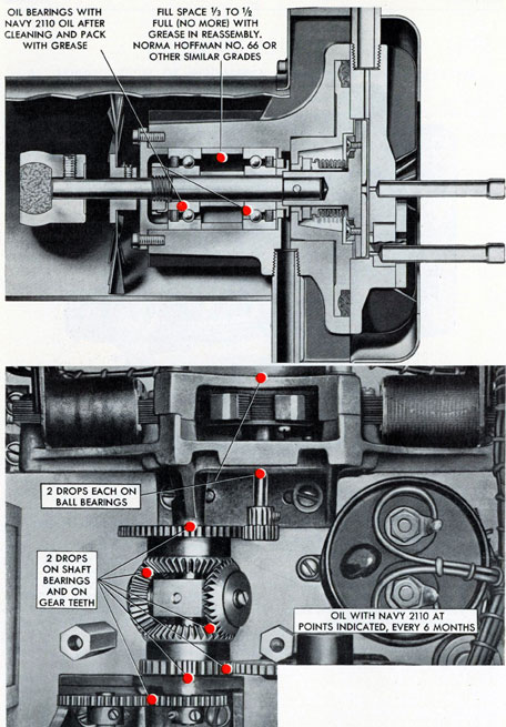
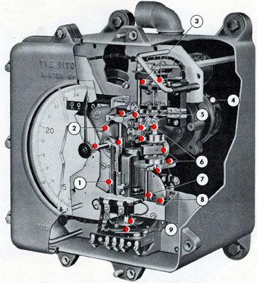
1. 8 OR 10 DROPS OF OIL (NAVY 3050) IN OIL CUP, EVERY 6 MONTHS 2. REPACK MOTOR BALL BEARINGS, AND REFILL REDUCTION GEAR CASE WITH NORMA-HOFFMAN GREASE NO. 66, OR SIMILAR GRADES WHENEVER MOTOR IS DISASSEMBLED 3. 2 OR 3 DROPS OF OIL (NAVY 2110) ON GEARS, COUNTER WORM SHAFT AND BEARINGS, EVERY 6 MONTHS 4. 3 DROPS OF OIL (NAVY 2110) IN EACH BEARING, EVERY 6 MONTHS
5. 2 OR 3 DROPS PURE SPERM OIL OR NAVY 2110 OIL IN TRANSMITTER BEARINGS, EVERY 12 MONTHS 6. 2 DROPS OF OIL IN MOTOR BEARINGS (NAVY 2110) EVERY 6 MONTHS 7. 2 DROPS OF OIL (NAVY 2110) BETWEEN WASHERS AND GEAR, EVERY 6 MONTHS 8. 2 OR 3 DROPS OF OIL (NAVY 2110 ON GEAR TEETH, EVERY 6 MONTHS
Top-Figure 9-2. Lubrication points, rotary pump.
Bottom-Figure 9-3. Lubrication paints, constant frequency control unit.
114
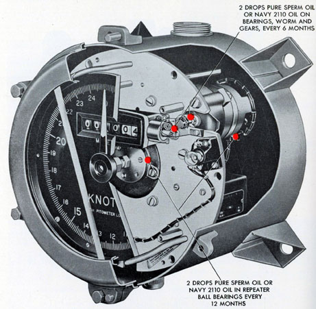
OIL AT POINTS SHOWN WITH NAVY 2110 OIL, EVERY SIX MONTHS, EXCEPTION IS THE BALL BEARINGS ON REPEATER AND TRANSMITTER, WHICH SHOULD BE OILED EVERY 12 MONTHS WITH PURE SPERM OIL.
1. 2 OR 3 DROPS IN LEAD SCREW YOKE OIL HOLE
2. 2 OR 3 DROPS
1 OR 2 DROPS AT ENDS OF JACKSHAFT AND FOLLOW-UP SHAFT. KEEP OIL AWAY FROM CONTACTS AND SLIP RINGS
4. 2 DROPS IN TRANSMITTER AND REPEATER BALL BEARINGS SEE INSTRUCTIONS.
5. 2 DROPS ON SHAFT BEARINGS AND ON GEAR TEETH
6. 2 DROPS IN DIFFERENTIAL BEARINGS, AND ON ALL GEAR TEETH
7. 2 DROPS ON ROLLER, PIVOT AND ROD
8. 5 DROPS SPREAD OVER DISK
9. 2 DROPS IN EACH MOTOR BEARING AND IN ALL GEARS