MERCURY DIFFERENTIAL MANOMETER
AND ELECTRONIC LOGS
18
DESCRIPTION
A. GENERAL DESCRIPTION
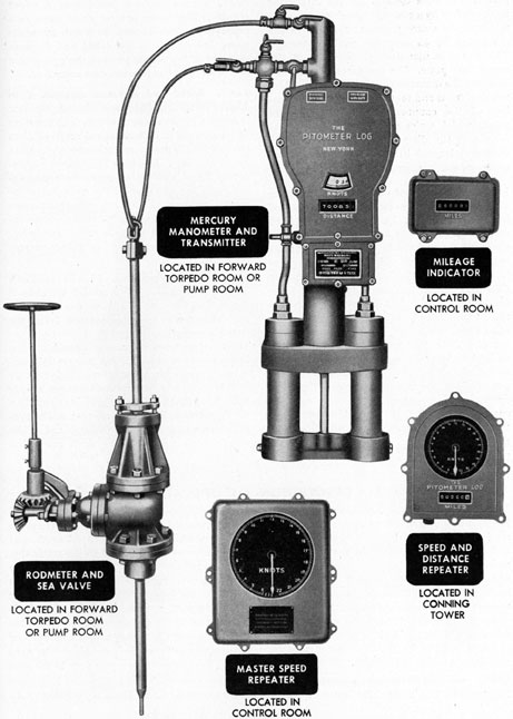
18A1. General. The mercury differential
manometer underwater log (Figure 18-1) is
made by the Pitometer Log Corporation, New
York, New York. This type of underwater
log derives its name from the fact that hydraulic pressures actuate a column of mercury
in a mercury manometer. The movement of
the column of mercury, caused by dynamic
pressure from the rodmeter, is the actuating
force that operates the system. This system
consists of the following components: rodmeter, sea valve, manometer, transmitter,
master speed repeater, speed and distance repeater, and a mileage indicator.
18A2. Rodmeter. (See Figure 18-1.) The
rodmeter, commonly called the sword, is located in the forward torpedo room or in the
pump room below the light draft water line.
This rodmeter is identical with the rodmeter
used with the Pitometer rotary balance type
log. It projects through the hull of the ship
into the water and is the unit in which static
and dynamic pressures are produced and
transmitted to the mercury differential manometer. When in use, the rodmeter extends
outside the hull for a distance of approximately 2 feet. Being located in the forward
part of the ship, the rodmeter contacts water
least disturbed by the movement of the ship.
18A3. Sea valve. (See Figure 18-1.) The
sea valve provides a means of closing the
opening through which the rodmeter passes
when it is withdrawn or raised to its fully
secured position. The sea valve is located in
the forward torpedo room beneath the deck.
In some of the earlier ships, it is located in
the forward part of the pump room. A tube
connects the spigot and flange on the underside of the sea valve assembly with the outer
hull, where it is welded to, a flange and guide
bushing. The guide bushing forms the lower
support for the rodmeter. A valve extension
is mounted on top of the sea valve and forms
an upper support for the rodmeter. A packing
gland is mounted on the valve extension to
provide a leakproof seal between the rodmeter and the sea valve.
18A4. Mercury differential manometer. (See
Figure 18-1.) The mercury differential manometer is a U-tube of special design, containing mercury. It is mounted in gimbals so that
the assembly will tend to remain in a vertical
position regardless of the roll and pitch of the
ship. The two larger outer tubes of the manometer are connected at their base. A small
central tube connects this base with a float
chamber in which the mercury rises and falls
with changes in the ship's speed. The top
of the float chamber opens into a gear chamber
which is connected to, the upper or static line
from the rodmeter. Dynamic pressure from
the rodmeter is hydraulically transmitted to
the lower nipple of the manometer which is
connected through piping to both side tubes.
A hard rubber float filled with mercury supports a bronze gear rack which is meshed with
a gear on the shaft in the gear chamber. The
shaft extension extends out of the gear chamber cover through a grease seal gland. Hose
nipples, vent cocks, a bypass valve, and shutoff cocks are mounted in the hydraulic lines
connecting the rodmeter with the mercury
columns.
18A5. Transmitter. (See Figure 18-1.) The
transmitter is mounted in an aluminum case
which is secured to the manometer gear chamber. A distance integrator cam and the speed
dial are mounted as a unit on the mainshaft,
which is coupled to the shaft extension of the
manometer. The speed dial is positioned
directly by the mercury in the float chamber,
and will indicate the ship's speed in knots
without electrical connections. This speed
indication is transmitted to the master speed
repeater, or in some cases to speed repeaters
only, by a self-synchronous transmitter. Distance is obtained from the speed element by
means of a time-controlled mechanical
212
Figure 18-1. Components of mercury differential manometer underwater log system.
213
integrator. The time element for the integrator
is introduced by a constant speed synchronous
motor, or by a direct current motor which is
controlled by an accurate clock movement.
The motor is mounted on the back of the
motor base plate. The integrator mechanism
operates the distance counter which registers
nautical miles and tenths of a mile. The turning of the countershaft operates contact
points which make and break the electrical
circuit to the distance repeaters (magnetic
counters) located in the speed and distance
repeater, and in the mileage indicator.
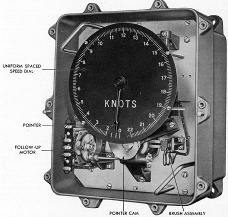
18A6. Master speed repeater. (See Figure
18-1.) The master speed repeater is located
in the control room. Its functions are: (1) to
receive speed indications from the self-synchronous transmitter in the transmitter; (2)
to convert these indications from the irregularly spaced speed dial of the transmitter
(Figure 18-4) to a uniformly spaced dial (Figure 18-9); (3) to transmit these speed indications to the speed and distance repeater, the
gyro speed corrector, and the torpedo data
computer. The interior mechanism is mounted
on a plate which is removable from the case
so that the complete unit may be removed for
purposes of inspection and tests. The self-synchronous repeater in this unit receives
speed indications from the self-synchronous
transmitter in the transmitter case. The self-synchronous repeater in the master speed repeater actuates a follow-up motor which
drives a cam, thereby positioning a speed
pointer. The speed pointer shaft actuates a
self-synchronous transmitter which transmits
speed indications to the speed and distance
repeater in the conning tower, the gyro speed
corrector, and the torpedo data computer.
18A7. Speed and distance repeater. (See
Figure 18-1.) The speed and distance repeater
is located in the conning tower. The function
of this unit is to indicate speed received from
the self-synchronous transmitter of the master
speed repeater. Distance indications are received by an alternating current electromagnet from the impulses of the contacts in the
transmitter case. This electromagnet operates
a distance counter which records distance indications in units of 1/10 mile. In earlier
ships the electromagnet is direct-current
operated.
18A8. Mileage indicator. (See Figure 18-1.)
The mileage indicator is located in the control
room. The function of this unit is to receive
and record distance indications from the
transmitter mechanism.
18A9. Constant frequency supply. Some
installations of the mercury differential manometer underwater log system include another
unit known as the constant frequency supply
unit. The function of this unit is to supply a
constant 60-cycle 115-volt current to the synchronous motor in the transmitter, and to the
synchronous motors in the shaft revolution
indicators.
B. DESCRIPTION OF OPERATION
18B1. Hydraulic pressures. While the ship
is stationary, the water pressures in the rodmeter tubes are equal (static pressure only),
and the mercury columns in the manometer
are at equal heights. As soon as the ship gets
underway or increases speed, the forward
motion creates additional pressure through
the dynamic (forward) orifice in the rodmeter,
while the pressure through the static orifices
remains the same. This causes the center
mercury column in the manometer to rise,
thereby operating the system.
18B2. Mercury differential manometer. (See
Figures 18-2 and 18-3.) The lower nipple of
the mercury manometer piping is hydraulically connected to the dynamic line from the
rodmeter, while the upper central section of
the manometer is connected to the static line
from the rodmeter. The static pressure on top
of the center mercury column remains the
same. As the dynamic pressure increases, due
to the forward movement of the ship, it is
transmitted to the side mercury columns. This
extra pressure (dynamic) causes the mercury
column to rise in the float chamber. The hard
rubber float supporting a gear rack in the gear
chamber rises with the mercury and actuates
the transmitter mechanism. A few ships have
214
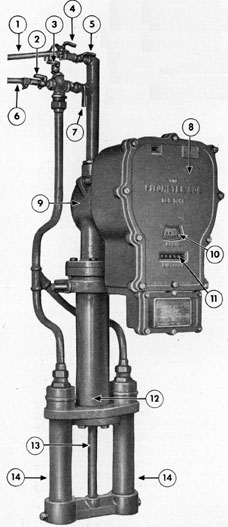
1. STATIC LINE
2. DYNAMIC SHUT-OFF VALVE
3. DYNAMIC VENT COCK
4. STATIC VENT COCK
5. STATIC SHUT-OFF VALVE
6. DYNAMIC LINE
7. BY-PASS VALVE
8. TRANSMITTER CASE
9. GEAR CHAMBER
10. SPEED DIAL
11. DISTANCE COUNTER
12. FLOAT CHAMBER
13. MANOMETER CENTER TUBE
14. MANOMETER SIDE TUBES Figure 18-2. Front view of manometer and transmitter.
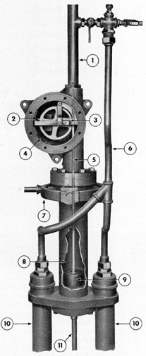
1. STATIC LINE
2. DRIVEN GEAR
3. ROLLER ARM SPRING
4. GEAR CHAMBER
5. GEAR RACK
6. DYNAMIC LINE
7. GIMBAL RING
8. FLOAT CHAMBER
9. FLOAT
10. MANOMETER SIDE TUBES
11. MANOMETER CENTER TUBE Figure 18-3. Installation of float and gear rack.
215
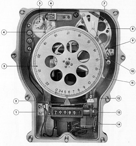
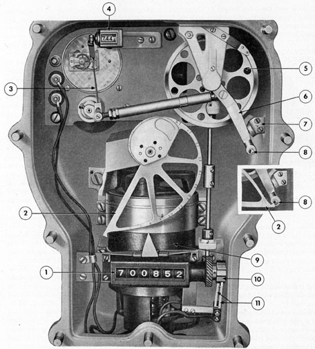
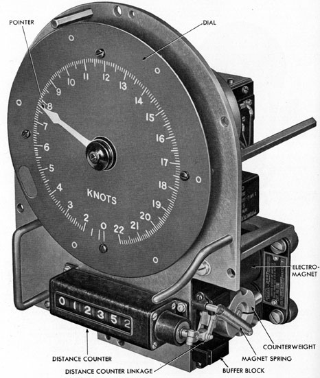
1. DISTANCE COUNTER
2. POINTER
3. SQUARE FUNCTION SPEED DIAL
4. OPERATING ARM FOR TIMING COUNTER
5. ESCAPEMENT
6. TIMING COUNTER
7. INTEGRATOR WHEEL BRAKE
8. INTEGRATOR WHEEL
9. INTEGRATOR DRIVING PAWL
10. INTEGRATOR ARM
11. INTEGRATOR CAM
12. SELF-SYNCHRONOUS SPEED TRANSMITTER
13. STAR WHEEL
14. REPEATER CONTACTS
Figure 18-4. Transmitter, cover removed.
216
a spiral gear assembly instead of the conventional circular gear. The spiral gear is designed to spread the dial graduations at the
low-speed end of the dial.
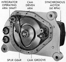
Figure 18-5. Sixty-cycle alternating current integrator
timing assembly, cover removed.
18B3. Transmitter. The movement of the
float in the float chamber is transmitted to the
mainshaft of the transmitter mechanism. This
mainshaft carries the distance integrator cam
and the master speed dial assembly. The speed
dial (Figure 18-4) is positioned directly by the
movement of the mercury in the float chamber
and indicates the ship's speed in knots without electrical connections. Through gearing,
the mainshaft operates a self-synchronous
transmitter which transmits speed indications
to a self-synchronous repeater in the master
speed repeater. On ships not having a master
speed repeater, the speed indications are
transmitted directly to the speed indicator in
the speed and distance repeater. Distance is
obtained from the speed element by a mechanical integrator in the following manner:
A synchronous motor operating on controlled
60-cycle, 115-volt alternating current, turns a
shaft at a speed of 60 revolutions per minute.
This shaft is geared, in a ratio of 15 to 1, to a
spur gear under the clock plate cover. The
spur gear (Figure 18-5) has a cam groove cut
in its face, and a roller in this groove swings
an operating cam through an arc of approximately 20 degrees every 15 seconds, or 240
strokes per hour. A timing counter (Figure
18-6) registers the number of strokes of the
operating arm, and provides a means of checking the operation of the integrator unit. The
operating arm is mechanically connected to
the integrator arm by a spring-loaded integrator link. The lower end of the integrator
arm carries a knife-edge which strikes the
distance integrator cam when the arm is
pulled over by the action of the operating arm
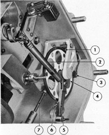
and link. The distance integrator cam is so
designed that the angle through which the
integrator arm moves to strike the cam every
15 seconds is directly proportional to the
speed of the ship. For example, the faster the
speed of the ship, the longer the sweep of
the integrator arm will be every 15 seconds,
while at zero knots the knife-edge just clears
the tip of the cam, and cannot swing at all
(see inset, Figure 18-6). A tension spring
inside the integrator link allows the operating arm to move when the integrator arm is
restrained by the cam. A pawl mounted on
the integrator arm drives the integrator wheel
in a clockwise direction (Figure 18-7). A stop
pawl mounted at the upper left side of the
integrator wheel prevents the wheel from
turning in a counterclockwise direction. A
brake engages the upper right side of the integrator wheel to keep it from jumping ahead
when the knife-edge strikes the cam. The
integrator wheel drives a shaft which operates
the master distance counter (Figure 18-8).
This counter registers nautical miles and
tenths; one complete revolution of the shaft
of the counter being equivalent to one mile.
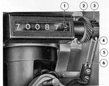
A ten-tooth star wheel, mounted on the end
of the shaft of the counter, operates electrical
contacts. One contact is made and broken
each tenth of a mile, and the resulting electrical impulse is transmitted to the electromagnet-operated counters in the speed and
distance repeaters, and in the mileage indicator.
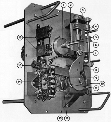
18B4. Master speed repeater. (See Figure
18-9.) The shaft of the self-synchronous repeater in the master speed repeater is
217
1. DISTANCE COUNTER
2. INTEGRATOR CAM
3. OPERATING ARM
4. TIMING COUNTER
5. INTEGRATOR WHEEL
6. INTEGRATOR ARM
7. STOP BRACKET
8. INTEGRATOR ARM KNIFE-EDGE
9. SELF-SYNCHRONOUS SPEED TRANSMITTER
10. STAR WHEEL
11. REPEATER CONTACTS
Figure 18-6. Integrator cam at 15-knot and zero-knot positions.
218
1. STOP PAWL
2. INTEGRATOR LINK ASSEMBLY
3. WHEEL BRAKE
4. INTEGRATOR WHEEL
5. INTEGRATOR ARM
6. WHEEL DRIVING PAWL
7. COUNTERSHAFT Figure 18-7. Integrator wheel control mechanism.
1. DISTANCE COUNTER
2. DRIVEN SPIRAL GEAR
3. STAR WHEEL
4. CONTACT POINTS
5. UPPER CONTACT SPRING
6. LOWER CONTACT SPRING Figure 18-8. Distance repeater contacts installed.
electrically positioned by the self-synchronous
transmitter in the transmitter mechanism. A
heart-shaped cam assembly (Figure 18-10) is
mounted on the repeater shaft extension, and
actuates a pivoted arm which in turn operates
electrical contacts. A roller which normally
rides in the lowest part of this cam (Figure
18-11) is mounted on one end of a pivoted
arm which has the center contact assembly
mounted on the other end of the arm. A spring
holds the roller in contact with the heart cam
at all times. For normal changes in speed, the
roller will maintain its position in the low
spot of the cam as shown at the top center of
Figure 18-11. For sudden abnormal changes
in speed, the roller may be momentarily
forced out of its normal position as shown at
the left in Figure 18-11, but the spring will
return the roller to the low point when the
follow-up motor drives the follow-up contact
assembly, and with it, the center contact assembly, to the proper position.
The follow-up contact assembly is driven
through the same number of degrees as the
heart cam without imposing any appreciable
load on the self-synchronous repeater. Likewise, the use of the heart cam prevents the
excessive load on the self-synchronous repeater which would result if the repeater
armature were restrained from following the
speed transmitter during abnormal speed
changes.
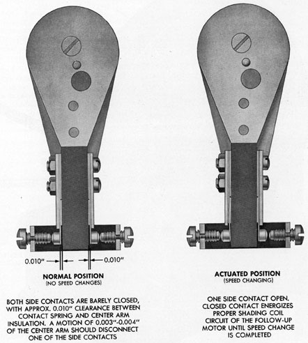
The center contact assembly normally
stands with both spring contacts touching the
contact screws of the follow-up contact assembly (Figure 18-12). As the center contact
moves, it opens one of the two contacts that
control the shading coil circuits of the follow-up motor through slip ring and brush assembly. This motor will run in either direction,
depending on which contact is opened by the
action of the heart cam. When the heart cam
is stationary, both shading coils are energized,
holding the motor stationary.
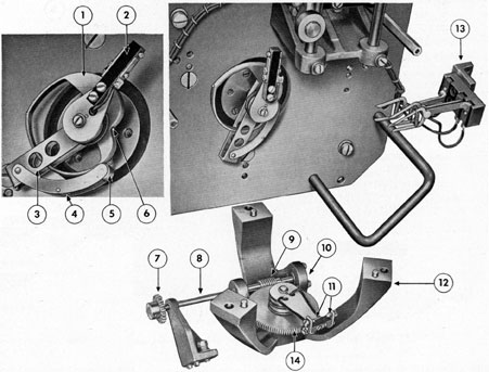
The follow-up motor drives a worm gear
(Figure 18-11) which carries the follow-up
contact assembly. The worm gear is mounted
on a shaft, the other end of which carries a
pointer cam which raises and lowers a carriage
slide. This carriage slide has a gear rack on
one side which engages the pointer shaft gear
(Figure 18-10).
The pointer shaft gear is mounted on the
pointer shaft extension of the self-synchronous transmitter. The pointer cam will always turn through the same number of
degrees as the heart cam (and hence the same
number of degrees as the square low-speed
dial of the transmitter mechanism) for a given
speed change. However, the pointer cam is so
designed that the carriage slide will move
with a linear function as the cam rotates with
its square low function. As the pointer cam
moves the carriage slide upward or downward,
the pointer shaft extension of the self-synchronous transmitter is turned, the pointer is
positioned to indicate speed in knots on the
linear dial and the linear speed indications
are electrically transmitted to the speed and
distance repeater.
18B5. Speed and distance repeater. (See
Figure 18-13.) The self-synchronous repeater
in the speed and distance repeater is electrically
Figure 18-10. Master speed repeater, pointer and dial removed.
connected to the speed transmitter in
the master speed repeater, and repeats speed
indications of this transmitter. The distance
counter is electrically operated by an a.c.
electromagnet which receives its electrical
impulses from the contact assembly in the
transmitter case. Some ships have d.c. electromagnets operating the distance counter. In
some ships the speed repeater has a square
function (unevenly spaced) dial (Figure
18-4), and is controlled by the self-synchronous transmitter in the transmitter case. Some
of these ships have a master speed repeater
which was later installed in order to provide
a uniformly spaced dial for use with the torpedo data computer.
18B6. Mileage indicator. The mileage indicator electrically repeats the distance indications of the transmitter mechanism. A
six-figure, reset-type counter indicates units
of 1/10 nautical mile. The counter is operated
by an a.c. electromagnet which receives an
impulse every 1/10-mile from the contact assembly in the transmitter case in the same
manner as distance is registered on the speed
and distance repeater.
221
1. HEART CAM
2. CENTER CONTACT ASSEMBLY
3. PIVOTED ARM
4. ROLLER SPRING
5. ROLLER
6. HEART CAM NOTCH
7. WORM SHAFT GEAR