15A1. General. When it becomes necessary
to remove the main balance arm, auxiliary
balance arm, main force arm, or the A-spring
from the instrument, the procedure generally
followed is to remove the instrument from
the ship and overhaul it on a tender or in
a shop. The most practical means of checking the instruments before installation in the
ship is to operate them in the shop under the
same conditions as encountered in service.
After overhaul, the cam and pointer should
be adjusted to the zero position (see Section
15A6), and the instrument should be balanced
(see Section 15A7), and calibrated in the
shop. The bellows should be tested, if necessary, under water pressure of 300 psi.
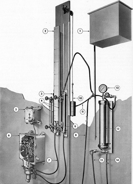
15A2. Equipment required. (See Figure 151.) The equipment described below is the
minimum required for properly testing the
Bendix log. It an be assembled and installed
at a tender or base shop from readily available material. The following hydraulic equipment is necessary: a water storage tank, or
water line with connection, static pressure
tank, dynamic pressure tank, pressure storage
tank, pressure gage, air compressor, water
level gages, knot scale, hydraulic hose, and
fittings and connections. This equipment is
described in the following paragraphs.
15A3. Knot scale. (See Figure 15-1.) The
knot scale is laid off from the values listed
below, and is preferably made of metal. The
lines are cut with a milling machine or jig
borer, so that the distances from the zero line
can be accurately measured. This scale is
suitable for use only with fresh water in tanks
and system, and is designed for calibrating
Bendix log instruments only. Pressure values
from rodometers of other manufacturers may
differ from the pressure values indicated here,
probably necessitating the use of a different
scale. However, with a correct scale, this
equipment may be used on other types of logs
operating on the principle of pressure differences from a rodmeter. The scale should
be mounted so that it can be shifted upward
and downward approximately 6 inches, or
else the left-hand static tank must be movable. The distances to be marked above zero,
corresponding to knots are listed as follows:
Knots
Distance (in.) above zero
1
0.543
2
2.170
3
4.879
4
8.674
5
13.553
6
19.516
7
25.383
8
34.696
9
43.912
10
54.212
15A4. Pressure tanks. (See Figure 15-1.)
Two pressure tanks are mounted, one on
each side of the knot scale. The tank on the
right side supplies dynamic water pressure.
The left-hand tank supplies static water
pressure. Provision is made for raising and
lowering the right-hand (dynamic tank, while
the left-hand (static) tank is stationary, unless the scale is stationary, in which case
the latter tank must be movable, too. When
the dynamic tank is elevated above the static
tank, the head, or difference of level of
water, creates a pressure difference which is
equal to the dynamic pressure at some known
speed. Water level gages are mounted in
front of the pressure tanks and show the
exact level of water in each tank. The knot
scale mounted between these pressure tanks
is calibrated in knots and enables the water
level to be read closely, even at low speeds.
The tanks are made of 3- or 4-inch heavy-duty pipe, preferably brass, approximately 18
inches long, with heavy threaded caps at each
end. The glass tubing and gage fittings should,
be able to withstand a pressure of 400 psi for
safety. Shut-off cocks should be mounted on
the lower ends, ahead of the nipples. Shutoff
197
1. WATER STORAGE TANK
2. KNOT SCALE
3. STATIC PRESSURE TANK
4. WATER LEVEL GAGES
5. SPEED AND DISTANCE INDICATOR
6. MASTER TRANSMITTER INDICATOR
7. STATIC HOSE
8. AIR COMPRESSOR LINE (OPTIONAL)
9. DYNAMIC PRESSURE TANK
10. COUNTERWEIGHT
11. AIR LINE TO STATIC PRESSURE TANK
12. PRESSURE GAGE
13. PRESSURE STORAGE TANK
14. VENT LINE
15. HAND PUMP PRESSURE LINE
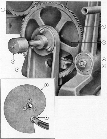
5. CAM
6. CAM FOLLOWER (BEARING)
7. MAIN FORCE ARM EXTENSION
Figure 15-2. Cam positioned prior to setting pointer to exact zero.
199
cocks are not required at the top. When
mounted as shown in Figure 15-1, the left-hand (static) tank is connected to the static
line. The right-hand (dynamic) tank is
suspended on a chain, or cord, which is connected to a counterweight so that it may be
moved upward or downward as desired. The
tanks should be mounted so that the zero
water level is at least 4 feet above the bellows.
However, the shop ceiling may be a determining factor, and may not permit raising the
dynamic tank to the 10-knot mark on the
scale. In this case the distance of the zero
water level above the bellows will have to be
less than 4 feet.
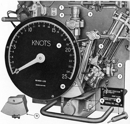
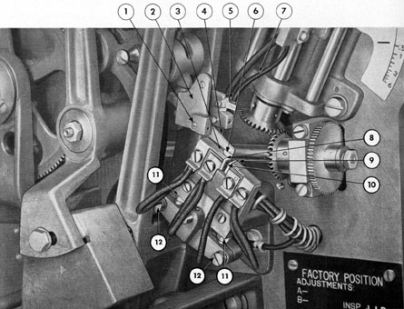
1. "A1" ADJUSTMENT KNOB
2. "A" ADJUSTMENT ASSEMBLY ATTACHED TO MAIN BALANCE ARM
3. "A2" RING TURNED ALL WAY DOWN
4. REFERENCE MARKS
5. REFERENCE POST
6. CONTACT ARM
7. CONTACT ADJUSTING SCREWS
8. "B" SPRING ASSEMBLY REMOVED
9. MAIN BALANCE ARM ADJUSTING SCREWS
10. CONTACT LOCK SCREWS
11. MAIN BALANCE ARM COUNTERWEIGHT REMOVED
1. STRING
2. A ADJUSTMENT, ASSEMBLY
3. CONNECTOR SCREW CONNECTION
4. B SPRING
5. CONTACT ARM
6. AUXILIARY BALANCE ARM
7. MAIN BALANCE ARM
8. MAIN FORCE ARM
9. CONNECTOR SCREW Figure 15-4. Balancing master transmitter indicator, Step 2.
15A5. Water and air connections. (Figure
15-1.) The hose connecting the dynamic tank
to the lower fitting of the bellows must be
long enough to permit the dynamic tank to
be raised to the extreme upper position of 10
knots. The nipples on the upper ends of the
tanks are connected together, and the hoses
are so arranged that they can be connected
to either a water supply, or to a water
storage tank, mounted from 8 to 12 feet above
the tanks; and to an air pressure line capable
of delivering a pressure of at least 100 psi.
A pressure storage tank mounted as shown
in the illustration permits the use of higher
pressures which are developed in the top of
the tank when water is pumped up into it
from below by a hand pump. An air-pressure
gage should be mounted on either the dynamic
or static tanks, on the common air line, or on
the pressure storage tank. Connect the upper
bellows fitting to the static tank.
15A6. Aligning cam and pointer to exact
zero position. (See Figure 15-2.) Remove
the pointer and dial before calibrating the
log; align the cam and pointer to the exact
zero position as follows: Manually turn the
driven gear on the power motor drive gear
assembly until the bearing (follower) on the
main force arm extension falls into the groove
provided in the cam as shown in the illustration. Install the dial and pointer with the
pointer set at zero position on the dial.
Manually turn the power motor-driven gear
until the pointer registers 1.2 knots on the
dial. This is the exact zero setting of the
pointer and cam. Loosen the pointer screw
and move the pointer back to zero position on
the dial. Tighten the pointer screw and pin
the pointer to the pointer hub.
15A7. Balancing master transmitter indicator. (See Figures 15-3, 15-4, and 15-5.)
a. Whenever the A-adjustment assembly is replaced, or whenever the arms are
removed, it is necessary to balance the log
mechanism before calibration. The first
steps in balancing the master transmitter indicator are accomplished as follows: Remove
the counterweight from the bottom of the
main balance arm by removing the screw and
lock washer that secure the counterweight to
the arm. Turn the A2-adjustment ring in a
clockwise direction as far as possible. This
will stretch the A-spring. Remove the B-spring by unscrewing the B-spring connector
screw from the rocker on the top right side
of the main balance arm. Energize the power
motor. Position the contact block so that
the contact arm is in a neutral position when
the pointer reads zero by loosening the two
lock screws at the bottom of the contact
block, and then turning the contact block
adjusting screws until the contact arm is
positioned in a neutral position. Align the
201
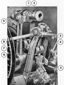
1. PIVOT SCREW
2. CONTACT ARM SUPPORT
3. HIGH-SPEED REVERSE CONTACT
4. CONTACT ARM
5. TERMINAL
6. CONTACT ARM CONTACT
reference marks on the reference post and on
the main balance arm by loosening the lock
nut on the rear of the main mounting
plate and turning the reference post until
the reference marks are aligned (Figure
15-3). Deenergize the power motor. Turn
the main balance arm adjusting screws
on the main force bearing so that the
contact arm will move through an are sufficient to position the arm contact on the
exact center of each high-speed contact, then
tighten the lock nut on each adjusting
screw.
b. The second step in balancing the
master transmitter indicator is accomplished
as follows: Disconnect the connector screw
on the A-spring from the rocker on the left
side of the main balance arm. Tilt the A-adjustment assembly to a horizontal position,
and tie it in this position so that it will clear
the rest of the mechanism as shown in Figure 15-4. Place the B-spring in the spring
202
force hub at the top of the auxiliary balance
arm, and install the B-spring connector
screw that secures the spring to the rocker in
the right side of the main balance arm. Install the adjusting nut and thin lock nut at
the top of the B-spring so that there is no
tension and no slack in the B-spring. Install
the counterweight on the bottom of the main
balance arm and secure it with a screw and
lock washer. Shift the position of the
counterweight on the main balance arm until the reference mark on the reference post
is aligned with the reference mark on the
main balance arm (Figure 15-3) when the
arm is freely balanced. When the reference
marks are aligned, pin the main balance
counterweight in position. It is not always
possible to pin through the old pin hole. In
such cases, a new hole should be drilled and
a pin installed through it. Be careful not to
get chips in any part of the instrument. Remove the string from the A-adjustment assembly and connect the A-adjustment assembly connector screw to the rocker at the left
side of the main balance arm. Tighten the
connector screw.
15A8. Preparing shop equipment prior to
testing. Fill both the static and dynamic
pressure tanks nearly to the top with fresh
water and vent the hydraulic system as
described in Section 11A5.
15A9. Testing equipment at surface pressure. (See Figures 7-2 and 7-3.) To operate
the unit at normal surface pressure, set the
valves of the bellows to the operating position. Vent both the static and dynamic tanks
to the same level at the zero point on the
knot scale. The top connections of the tanks
are open to the atmosphere. Energize the
master transmitter indicator. Set the instrument to zero by means of the C-adjustment as described in Section 13A4. Raise the
dynamic pressure tank to the desired knot
mark on the scale as illustrated in Figure 7-3.
If adjusted properly, the pointer of the master
transmitter indicator will indicate the same
speed. Lowering the dynamic tank to the
zero mark as shown in Figure 7-2 should
cause the master unit to return to a zero indication of the pointer.
15A10. Testing equipment (submerged condition). Connect the common pressure hose
at the top of the tanks to a controllable
supply of air, preferably from the pressure
storage tank. Apply air slowly, and test at
steps of 50 psi. Because of hose expansion
with pressure increase, the water level in the
tanks may change and the zero of the scale
may have to be lowered slightly. Pressure
beyond 200 psi is not necessary if the parts
operate satisfactorily up to this pressure.
No part of the bellows assembly should leak.
If the test under pressure (submerged condition) is satisfactory, release the air pressure from the top of the tanks. Do not
release the pressure by opening the vent
cocks on the bellows. Adjust the equipment
for dive error as described in Section 13E5.
15A11. Calibration of Bendix log in shop.
Shop calibration of the Bendix underwater
log is accomplished in the following manner:
a. Set the B-adjustment to zero and the
A1-adjustment to the factory adjustment
setting as indicated on the plate which is
mounted on the lower right-hand corner of
the main mounting plate.
b. Energize the instrument.
c. With the water levels at the zero
knot line of the knot scale and valves and
vent cocks at the operating (speed) position,
set the pointer at zero by means of the C-adjustment as described in Section 13A4.
d. Raise the water level in the dynamic
pressure tank to 5 knots and make the pointer
indicate 5 knots, plus or minus 0.10 knot, by
turning the A2 adjustment ring. The red
marks on the ring should line up with the
scribe marks on the axle.
e. Raise the water level to 10 knots and
observe the speed pointer. If it reads more
than 10.1 knots, turn the plug at the bottom
of the A spring until the pointer indicates
9.9 knots.
203
f. Lower the dynamic water level to 5
knots on the scale and repeat the operations
outlined in Section 15A11d.
g. Raise the dynamic water level to 10
knots on the scale and repeat the operations
outlined in Section 15A11e.
h. Repeat the operations outlined in
Sections 15A11f and 15A11g until the speed
indications of 5 knots plus or minus 0.10
knots, and 10 knots plus or minus 0.10 knots
are obtained. If, when raising the dynamic
water level to 10 knots on the scale, a speed
indication of less than 9.9 knots is obtained
on the speed dial, turn the plug below the A-spring outward until a speed indication of
10.1 knots is obtained.