5A1. General. Hydraulic power is used to
tilt the bow and stern planes. Each system
(bow and stern planes) has its own power
supply system. Except in emergencies, the
power facilities of each system are adequate
for its own individual operation independent
of power from the main hydraulic system.
The control units for diving and rising
are assembled in a diving control stand, located in the control room. There is a set of
controls for stern plane tilting, a set for bow
plane tilting, and a control valve for bow
plane rigging. The control panel also has diving indicators, gages, and motor switches.
Three methods of plane tilting are available at the control panel, based on three different sources of hydraulic power. They are
designated as follows:
a. POWER, in which power is developed
independently in each plane tilting system by
the motor-driven Waterbury A-end pump be
longing to that system.
b. HAND, in which power is developed
in the telemotor pump, connected to each system, by the manual efforts of the diving stand
operator.
c. EMERGENCY, in which power is obtained from the main hydraulic system.
EMERGENCY is used only when the
normally used POWER fails. HAND is employed when the other two sources are in
operative, or when silent operation of the
submarine is necessary to prevent detection
by the enemy.
In addition to bow and stern plane tilting, this chapter also contains a description
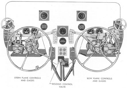
Figure 5-1. Diving control stand.
105
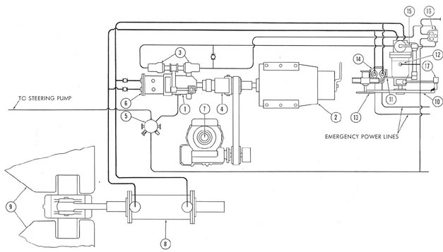
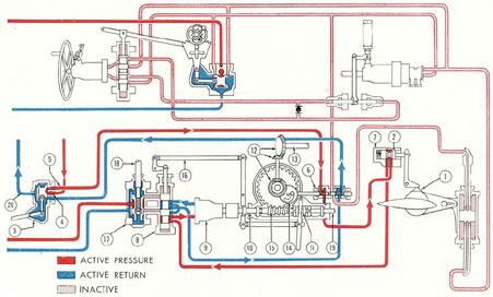
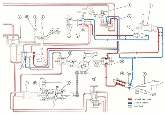
Figure 5-2. Piping diagram of stern plane system.
1) A-end pump; 2) motor; 3) control cylinder; 4) clutch; 5) vent and surge tank; 6) relief valve manifold; 7) capstan gear; 8) main cylinder; 9) stern
planes; 10) main diving wheel; 11) change valve handle; 12) telemotor pump; 13) emergency control wheel; 14) emergency control valve; 15) change valve;
16) vent and replenishing manifold; 17) pump-stroke setting lever.
106
of bow plane rigging and forward windlass-and-capstan operation. Although they derive
their hydraulic power from the main hydraulic system, they are very closely associated with bow plane tilting and are, therefore,
described in the bow plane system instead of
in connection with the main hydraulic system.
A schematic view of the bow and stern
plane systems and their associated equipment
is illustrated in Figure 7-3 at the back of the
book.
B. STERN PLANE SYSTEM
5B1. General arrangement. The units of the
stern plane system fall conveniently into
three groups:
a. The control units at the diving control
panel, consisting of handwheel, telemotor
pump, change valve, and emergency control
valve.
b. The power supply system, consisting
of a Waterbury A-end pump, the motor which
drives it, the control cylinder, and two pressure relief valves.
c. The main cylinder and planes assembly, consisting of the hydraulic cylinder, the
piston, the piston rod, the guide cylinder
and guide piston, and the tiller which tilts
the planes.
Figure 5-2 shows the units of the stern
plane system in their proper schematic arrangement. It also includes miscellaneous
equipment which will be described in detail
in the following paragraphs.
The power and control units of the stern
plane system are practically identical with the
corresponding units of the steering system
and hence, in the discussion which follows,
frequent reference is made to illustrations of
the steering system in Chapter 4.
5B2. Detailed description. a. The diving
control stand. Both the bow and the stern
diving planes are operated from the diving
control stand Figure 5-1. Stern plane controls
occupy the after half of the stand and bow
plane controls occupy the forward half. The
bow plane rigging control valve is at the bottom
center of the panel on certain classes of submarines.
We shall concern ourselves exclusively
here with the location of control units
for the stern plane system.
A schematic layout of the system as a
whole is shown in Figure 5-2. Its control units
correspond with those of the steering system,
and their structure and functioning will be
more clearly understood if frequent reference
is made to the detailed description of parts
in Section 4B2b. Similarities and differences
are pointed out as they occur.
1. The control panel. One immediate
difference to be seen between steering and
diving plane controls is that the diving plane
controls are all located on the front of a single
panel; the various valves and units themselves
are mounted behind the panel. Figure 5-3 is a
front view of the stern plane half of the
panel; Figure 5-4 shows the rear view.
2. The telemotor pump. The main wheel
(1, Figure 5-3) rotates the telemotor pump
(2) as on the steering stand. The function of
the telemotor pump, as in the corresponding
steering unit, is to drive hydraulic oil at low-pressure to one side or the other of the control cylinder, for POWER operation, or directly
to one side or the other of the ram for
HAND operation.
Like the steering stand telemotor pump,
the diving stand telemotor pump has a one
direction, variable-angle tilt-box. However,
the control shaft on the steering stand telemotor
pump has only two settings, POWER
and HAND, while the control shaft on the
diving stand may, theoretically at least, be
set at any angle from ZERO stroke to FULL
stroke, as shown by the pointer at the end of
the pump-stoke setting lever (3), and read
directly on the indicator dial (4).
In practice, the internal arrangement of
the control shaft is such that it can never be
set at absolute ZERO, that is, with the tilt-box
at neutral, since some hydraulic power must
be instantly available to the operator. To
operate it at FULL stroke would take more
physical strength than a normal man possesses.
This lever is usually set between 1/4-stroke
for POWER operation and 3/4-stroke for
107
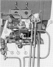
Figure 5-3. Front view of diving control stand (stern
plane).
1) Stern plane main wheel, POWER and HAND; 2) stern
plane telemotor; 3) stern plane pump stroke setting
lever; 4) indicator dial pump-stroke setting; 5) stern
plane change valve lever; 6) stern plane change valve
mechanical interlock; 7) stern plane emergency control
valve; 8) stern plane emergency control valve
handwheel; 9) stern plane emergency control valve
quadrant gear; 10) stern plane motor switch.
HAND operation, depending on the strength
of the operator.
3. The change valve. The function of
the change valve on the diving stand is exactly
the same as that of the corresponding unit on the
steering stand. It allows the operator to select
any one of the three available methods for
controlling, the diving planes POWER,
HAND, or EMERGENCY.
The only difference in internal structure
of the two change valves is that on the diving
stand the piston is moved up and down directly
by the action of a lever instead of having
a movable sleeve threaded into a revolving
stem. It is operated, through linkage, by the
change valve lever (5, Figure 5-3). A pointer
at the hand end of this lever indicates the
valve setting on the indicator plate of the
change valve mechanical interlock (6).
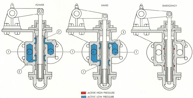
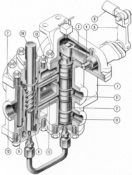
The diagram, Figure 5-5, shows the
change valve successively in all three positions:
POWER, HAND, and EMERGENCY.
The ports marked (1) go to opposite sides of
the telemotor pump; those marked (2) go to
the control cylinder; those marked (3) go to
the ram. Active oil from the main power
supply side of the line is shown in red; from the
stern plane telemotor, in blue.
Note that in the EMERGENCY position
the piston completely blanks off all lines
entering the valve body. The purpose of this
position is to prevent the high pressure oil
from the main hydraulic system (used in
emergency control) from reaching the telemotor
pump and motorizing it, with consequent
danger to equipment or personnel.
4. The emergency control valve. When
the change valve lever (5, Figure 5-3) is set
at EMERGENCY-NEUTRAL, its position in
the cross-shaped groove of the mechanical
interlock (6) permits the planes to be operated
by the emergency control valve (7). This
valve has the same function as the corresponding
unit on the steering stand; it permits flow
of hydraulic power from the main hydraulic
system (in the event of failure of normal
power) and directs it to one side or the other
of the ram. The valve is operated by the emergency
control valve handwheel (8) which,
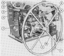
Figure 5-4. Rear view of diving control stand (stern
plane).
1) Stern plane telemotor; 2) stern plane change valve;
3) stern plane change valve linkage; 4) stern plane
emergency control valve; 5) stern plane emergency
control valve linkage; 6) stern plane vent and
replenishing valve manifold.
108
Figure 5-5. Change valve in three positions.
1) To telemotor; 2) to control cylinder; 3) to ram.
109
when turned, moves the quadrant gear (9),
and this in turn moves the emergency control
valve piston in or out.
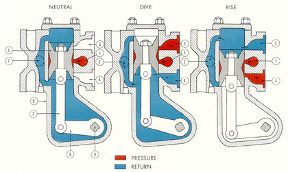
Figure 5-6 shows the emergency control
valve successively in its three positions. The
only difference in internal structure is that
here the piston is moved in and out directly
by the action of a lever, while on the steering
stand unit it is a movable sleeve threaded into
a rotating stem. The ports (1 and 2) go to the
main hydraulic system; the ports (3 and 4)
go to opposite ends of the ram, or actuating
cylinder. Oil from the supply line of the
main hydraulic system is shown in red; from
the return side in blue. Direction of flow is
shown by arrows.
5. Rear view of panel. A rear view of
the same section (stern plane controls) of the
control panel is shown in Figure 5-4. Shown
here are some of the units of which only the
control handles are visible in the front view
(Figure 5-3). Only part of the telemotor pump
(1) can be seen. At its end is mounted the
change valve (2) whose piston and linkage
(3) connect to the change valve hand lever on
the front of the panel. A portion of the
emergency
control valve (4) can be seen, as well
as its piston and linkage (5), which are moved
by the quadrant gear seen in the front view.
The vent and replenishing valve manifold is
shown at (6).
b. Power supply system. 1. The Waterbury
A-end pump. In normal operation, the
hydraulic power is developed by a Waterbury
A-end pump driven by a 7.1 horsepower electric
motor at a constant speed of about 440
revolutions per minute.
This pump is identical with the A-end
pump used in the steering system. It rotates
in a clockwise direction as viewed from the
motor end of the shaft. The speed and direction
of oil delivery for the actuation of the
main piston vary according to the angle of
the tilt-box which is governed by the action
of the control cylinder.
2. Control cylinder. As in the steering
system, the angle of the tilt-box is determined
by the action of the control cylinder (see
Figure 5-7) which raises or lowers the control
shaft of the A-end pump. Oil under pressure
is directed from the telemotor pump to either
side of the control cylinder (1) through the
Figure 5-6. Emergency control valve in three positions.
1) Port from supply line, main hydraulic system; 2) port from return line, main hydraulic system; 3) port from
stern plane ram, forward end; 4) port from stern plane ram, after end; 5) spool valve; 6) arm; 7) link;
8) shaft; 9) valve body.
110
Figure 5-7. Cutaway of control cylinder.
1) Cylinder; 2) piston; 3) bell crank; 4) crankshaft; 5) pump control arm; 6) mounting bracket; 7) port.
ports (7) and act's against the piston (2). Displacement
of the piston causes sidewise movement
of the bell crank (3), which is transmitted
to the pump control arm (5). The control
shaft is attached directly to the tilt-box of the
A-end pump so that the amount and direction
of the-oil pumped by the A-end pump are determined
by the action of the control cylinder.
Thus far, this is similar in operation to the
steering control cylinder. One difference may
be seen in Figure 5-7. The centering spring,
for returning the control shaft to a neutral
position, is installed on the shaft on the same
side at which it enters the Waterbury pump
housing, instead of on the opposite side as in
the steering system. Therefore, this spring is
much shorter than that in the steering system
installation, to correspond with the shorter
travel of the stern plane control cylinder
plunger.
3. Relief valves. A relief valve is installed in each line just behind the ports of
the Waterbury A-end pump, to prevent excessive
pressure from developing in whichever
line is functioning as the discharge line, by
bypassing the oil back to the suction side of
the pump.
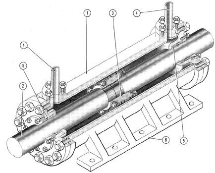
c. The ram. The hydraulic power developed
by the motor-driven Waterbury A-end
pump is transmitted to the stern planes
through the ram assembly (see Figure 5-8).
Unlike the steering system, the stern
plane system has only a single ram, a cutaway
111
Figure 5-8. Stern plane ram.
view of which is shown in Figure 5-9. It
consists of a hydraulic cylinder (1), through
which slides a piston rod (2). To move this
piston rod, hydraulic pressure is admitted to
either one of the two ports (4), forcing the
piston (3) to move away from that port. One
end of the piston is connected through
appropriate linkage to the stern plane tilting gear
so that, as the piston moves one way or the
other, it will tilt the planes to RISE or DIVE.
The after end of the piston slides through
a guide, into which a keyway has been milled.
A key attached to the piston shaft acts as a
drift stop to regulate piston travel and also
to keep the piston shaft, which consists of
two separate pieces, from unscrewing in the
piston. A pin mechanism which fits into a hole
provided in the forward end of the shaft
serves as a drift stop to regulate piston travel.
d. The capstan. The after capstan receives
its power from a chain drive directly
connected to the 7.1-horsepower electric
motor, which also drives the stern plane
Waterbury A-end pump. Thus, the power for
the capstan does not come from any of the
hydraulic units (see Figure 5-2).
When the capstan is to be used, a coupling
arrangement provides the means for connecting
the chain drive to the motor shaft. This
consists of a pair of spring-loaded pins attached
to Woodruff keys which have two
positions. In the ON position, the keys are
engaged in keyways in both the motor-shaft
collar and the chain-drive sprocket. In the
OFF position, the keys are slid over to one
side so that they engage only the motor-shaft
keyway, but not the chain-drive keyway. This
type of coupling does not disconnect the electric
motor from the Waterbury A-end pump.
On later classes of submarines, this clutch
has been eliminated, since the chain is removed whenever the capstan is not being used.
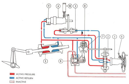
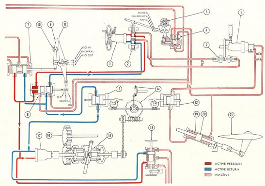
5B3. Operation. a. Power operation. Figure
5-10 illustrates the operation of the stern
plane system as a whole for tilting the planes
to RISE by POWER. The pressure side of
the line is shown in red, the return side in
blue, inactive in lighter red, and the direction
of flow is indicated by arrows.
The main wheel turns the shaft of the
telemotor pump (1), driving oil at low-pressure through the uppermost part of the
change valve (2) and into the after end of the
control cylinder (3). The piston of the control
cylinder moves forward, driving oil through
the return line and into the middle port of the
change valve, and from there back into the
return port of the telemotor pump, completing
the pressure-and-return cycle of the oil
in the low pressure, or control, system. The
control cylinder tilts the tilt-box in the motor
driven A-end pump (4) which delivers oil at
high pressure to the after end of the ram (5),
moving the ram forward and forcing oil out
of the other side of the ram and back to the
return port of the Waterbury A-end pump.
This completes the pressure-and-return cycle
in the high pressure system. The forward motion
of the ram, through the linkage, tilts the
stern plane to RISE. When the planes are
tilted to DIVE, the flow of oil is in the opposite
direction and the pressure side becomes
the return side.
b. Emergency operation. To operate by,
EMERGENCY power, the change valve (2)
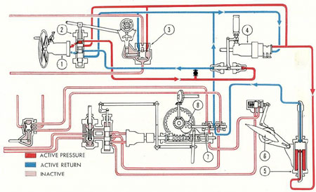
Figure 5-10. Flow diagram of stern plane system.
1) Telemotor; 2) change valve; 3) control cylinder; 4) motor-driven Waterbury A-end pump; 5) ram assembly;
6) emergency control valve; 7) quadrant gear; 8) emergency control handwheel; 9) pump-stroke control lever;
10) centering spring; 11) relief valve manifold.
is set at NEUTRAL-EMERGENCY. This
blanks off the lines from the telemotor pump
(1) so that high pressure oil cannot reach and
motorize it. At the same time it also places
the change valve hand lever in the horizontal
slot of the quadrant gear (7). The emergency
control handwheel (8) can now turn the
quadrant gear left or right, moving the spool
of the emergency control valve (6). This
admits high pressure oil from the main hydraulic
system directly to one side or the
other of the ram (5), tilting the stern planes
to RISE or DIVE.
c. Hand operation. For hand operation,
the change valve (2) is set at HAND. This
opens the lines from the telemotor pump (1)
directly to the ram (5). The pump stroke
lever (9) is set for a fuller stroke (the exact
setting depending on the operator's strength),
increasing the angle of the telemotor pump
tilt-box, so that more oil will be driven
through the lines for each turn of the wheel.
When the main wheel is turned to RISE
or DIVE, the telemotor pump delivers oil
directly to one side or the other of the ram
(5), instead of to the control cylinder as in
the POWER operation. The movement of the
ram tilts the stern planes to DIVE or RISE.
C. BOW PLANE SYSTEM
5C1. General. The bow plane tilting system is operated from the same control board
as the stern planes (see Figure 5-1). From the
control panel to the power supply units, the
bow plane tilting system is identical with the
stern plane system in equipment and operation.
This includes all diving control units,
A-end pump and motor, control cylinder, and
pressure relief valves. But beyond this point
there are important differences in the two
systems.
The hydraulic cylinder assembly differs
in that in the bow plane system the cylinder
moves and the piston is stationary, which is
the reverse of the arrangement for the stern
plane system.
In addition to the tilting mechanism, the
bow planes are also equipped with a rigging
mechanism, which pulls them flush against
the sides of the boat, or extends them to their
normal operating position. Since it might
damage the planes to rig them in while tilting
at any considerable angle there must also be
interlocks which automatically prevent rigging
and tilting at the same time. The rigging
mechanism receives its power from the main
hydraulic system. However, because it functions
as an essential unit of the bow plane
controls, it is more convenient to describe it
as part of the bow plane system.
The forward windlass-and-capstan
operating gear, which also receives power from
the main hydraulic system, is described in
this section, since it is mechanically
connected,
through a clutch, with the rigging
mechanism.
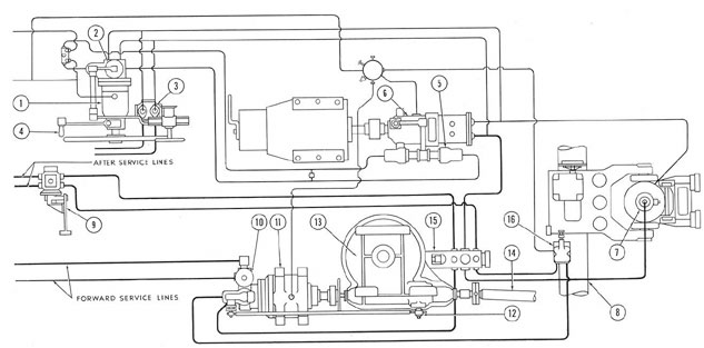
Figure 5-11 shows a general schematic
diagram of the layout of units in this system.
5C2. Detailed arrangement. a. The tilting
mechanism: power and control. As indicated,
Waterbury A-end pump power supply and
controlling, devices for the bow plane tilting
system are identical with those of the stern
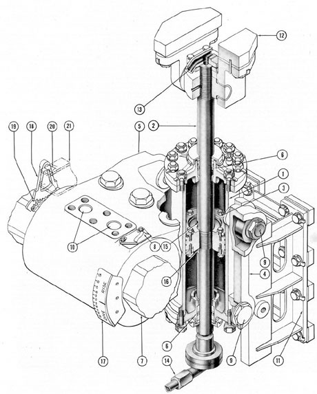
Figure 5-13. Cutaway of bow plane ram.
1) Hydraulic cylinder; 2) piston rod; 3) piston head; 4) linkage; 5) tiller; 6) packing; 7) plane stock; 8) cam;
9) link pins; 10) taper pin holes; 11) cylinder guide bearing; 12) securing pad; 13) port to piston rod; 14) port
to piston rod; 15) port to top of piston head; 16) port to bottom of piston head; 17) hub indicator dial;
18) sector gear; 19) quadrant gear; 20) angle transmitter shaft; 21) electric angle transmitter box.
116
plane system just described (see Section 5B2).
The bow plane tilting controls occupy the
forward half of the control board (see Figure
5-1).
b. Cylinder and planes assembly. In the
stern plane system, the cylinder is fixed, or
stationary, and the piston moves. In the case
of the bow planes (see Figure 5-12), the piston
rod (1) is fixed to the overhead frame (2) and
the cylinder (3) slides up and down on it. A
heavy double crank, connected through linkage (7) to the body of the cylinder, serves as
the tiller (4) which, through the stocks (5),
tilts the bow planes (6).
Figure 5-13 shows a cutaway of the bow
plane mechanism. The stationary piston rod
(2) has a hole lengthwise through its center,
from the top of the piston rod down to a point
just above the piston. This hole leads into two
ports, the edge of one of which (15) is shown
just above the piston head (3). Another hole
exactly like it (shown in the "broken" portion
of the rod near the bottom of this view) leads
from the bottom of the piston rod to similar
ports, one of which (16) can be seen under the
piston head. The pressure fittings (13 and 14)
go to the hydraulic pressure lines. Oil enters
at either of these fittings and goes through the
hole and out the ports on either side of the
piston head, forcing the cylinder (1) to slide
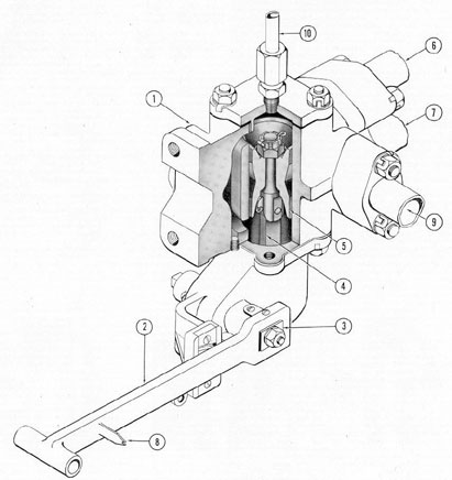
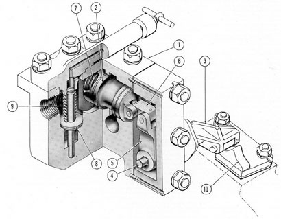
Figure 5-14. Cutaway of rigging control valve.
1) Valve body; 2) hand lever; 3) shaft for hand
lever; 4) link; 5) spool valve; 6) port to B-end motor;
7) port to B-end motor; 8) position pointer;
9) supply port from after service line; 10) vent line.
117
up or down. The linkage (4) moves the tiller
(5), into the hub of which are fastened the bow
plane stocks (7). The cam (8) serves to actuate
the tilting interlock, which is described
in the next section. The holes (10) are for
taper pins (not shown) to hold the tiller shaft
firmly in place inside the hub.
The hub indicator dial (17), graduated in
degrees, shows the angle of rise or dive of the
bow planes. A quadrant gear (19) is bolted to
the bow plane stock. This engages with a sector
gear (18), suspended from an angle frame.
The position of the sector gear and planes is
transmitted electrically to an indicator on the
diving control stand, providing the operator
with a continuous indication of the tilt of the
bow planes.
c. The rigging mechanism. To bring the
bow diving planes flush to the hull, when not
actually in use, a mechanism is provided
which will rig them in. This mechanism
consists of two heavy connecting rods actuated,
through suitable linkage and gear trains, by
a Waterbury B-end motor in the forward
torpedo room and controlled by a rigging
control valve located at bottom center of the
diving control board in the control room a
change valve, and suitable interlocks, to protect
the system against operational errors.
Figure 5-14 shows a cutaway view of this
rigging control valve which is a spool-type
valve. The hand lever (2), through the
connecting link (4), moves the spool valve (5)
up and down, admitting pressure from the
main hydraulic system through the supply
port (9), out through the ports (6 or 7),
through the rigging interlock, tilting interlock, and change valve, to the B-end hydraulic
motor. The motor used is a No. 10-B Waterbury hydraulic motor, the only B-end motor
used on the vessel. A No. 10 Waterbury B-end
motor is installed because the power requirements
of the heavy rigging gear and the
forward windlass-and-capstan exceed the
capacity of a No. 5 Waterbury B-end. To rig
in, the handle is raised to the RIG IN
position; to rig out, it is lowered to the RIG OUT
position; the intermediate position is
NEUTRAL. The pointer (8) indicates these
positions on a name plate (not shown) attached
to the control board.
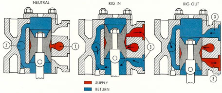
Figure 5-15 shows the internal structure
of the rigging control valve in each of its
three positions. The port marked (1) is
connected to the supply, or pressure, side of the
service line of the main hydraulic system; the
port marked (2) is connected to the return
side. The two ports marked (3) go through
the rigging and tilting interlocks to opposite
sides of the Waterbury B-end, hydraulic
motor. Oil from the supply side is shown in red;
oil from the return side in blue. Direction of
flow is indicated by arrows.
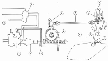
A diagram of the rigging gear layout as
a whole is shown in Figure 5-16. The rigging
Figure 5-15. Rigging control valve in three positions.
1) From after service line, supply; 2) to after service line, return; 3) to Waterbury B-end hydraulic motor.
118
control valve (1) receives the power from the
after service line (2) and directs this power
through the interlocks and change valve (3)
to one side or the other of the Waterbury
B-end motor (4), causing the shaft (5) to turn
in the required direction. The two bevel gear
boxes (6) transmit its motion to the upper
horizontal shaft (7) where, through a spur
gear (8), it is transmitted to the large sector
gears (9). These gears pull in or push out the
connecting rods (10) which rig the diving
planes (11) in or out. Leakage is prevented at
the point where the vertical shaft passes
through the pressure hull by a brass-lined
stuffing box containing 1/2-inch-square rings
of flax packing.
The diving planes (11) are connected to
the outboard end of the connecting rod by a
ball-and-socket joint (12) which permits
sufficient lateral rotation to allow for tilting at
least 25 degrees in either direction.
d. The rigging and tilting interlocks. If
an attempt were made to rig in the planes
while tilted, or to tilt them while rigged in,
either the hull or the planes, or both, would
be damaged. To prevent this, two valves called
interlocks are placed in the line through
which the hydraulic power must pass on its
way to the rigging and tilting mechanisms.
They are known as the rigging and tilting
interlocks.
The rigging interlock is a three-spool piston
valve, mechanically operated by the rigging
worm gear, which prevents tilting of the
planes until they are fully rigged out. The
interlock also acts as a throttle or cut-out, to
retard the flow of oil to the Waterbury B-end
motor when the planes are almost in the
rigged-in or rigged-out position. To allow the
rigging sector gears to come against their
positive stops gently, the line delivering the
pressure oil to the Waterbury B-end motor is
completely blocked by the valve when the
planes are in the fully rigged-in or rigged-out
position.
The tilting interlock is a single-spool
valve piston that prevents rigging in of the
planes when the planes are on any degree of
rise or beyond 15 degrees' dive. It will allow
rigging in when the planes are between 0 degrees'
and 15 degrees' dive.
1. The tilting interlock. The line carrying
power to rig out the planes must pass
through the tilting interlock (see Figure
5-17). When the planes are moving to zero
degrees' tilt, the cam (10) on the tiller will
raise the roller lever (3), turning the crankshaft (4) to the left which, through the bell
crank (5) and link (6) moves the spool valve
(2) to the OPEN position, allowing the oil
which operates the rigging gear to pass through
the valve. However, when the shaft turns in
either direction- RISE or DIVE -the high
point of the cam moves away from the roller on
the roller lever, and a return spring (7) pushes
the spool valve back into the CLOSED
position, cutting off the line to the rigging gear.
A special feature of this interlock deserves attention. If, while rigged in, the
planes should be accidentally knocked out of
position by enemy gunfire, depth charge, or
some other circumstance beyond the control
of the operator, the resulting tilt and position
of the cam might close the interlock and prevent rigging the planes out into their operating
position just when the need for diving
control was most urgent. To provide against
such an emergency, a check valve (8) is built
into the tilting interlock, which will allow
rigging power to pass through even when the
spool valve is closed, but only in the rigging
out direction.
2. The rigging interlock. The line carrying
power to tilt the planes must pass
through the rigging interlock (see Figure
5-18). The shackle (3) is connected to an
eccentric cam arrangement on the rigging
gear drive shaft. When the gear is in the fully
rigged-out position, this cam will have pushed
the piston valve spool (2) all the way to the
right, thereby opening the ports (5) in the
tilting line and allowing the power which
operates the tilting gear to pass. But with
the gear in the rigged-in position, the spool
valve (2) will be pulled to the CLOSED position,
cutting off the ports to the tilting gear
oil lines.
The rigging interlock has an additional
function. To eliminate the shock of the rigging
gear hitting the hard stop at each end
while rotating at full power, the rigging lines
themselves pass through the rigging interlock
in such a way that when the rigging gear is
approaching either the fully rigged-in or
fully rigged-out position, the rigging power
line will be partially closed off by the action
of the rigging interlock spool valve, bringing
the gear to an easy stop.
The check valves (7, Figure 5-18) allow
pressure oil to pass in one direction, RIG IN
or RIG OUT. They permit the operation of
the gear to begin when the cam action upon
the spool valve has closed off the rigging
lines. As the ports in these lines are then
opened by the spool valve, the check valves
close again.
e. Operation to rig out. Figure 5-19
shows the direction of flow of hydraulic
pressure in the rigging system for rigging out.
The pressure side of the line is shown in red,
the return side in blue; the direction of flow
is shown by arrows. Inactive oil is shown in
lighter red.
The bow planes are assumed to be
between zero tilt and 15 degrees' dive, and the
cam on the tiller hub (1) is therefore at its
highest point under the lever arm when at
zero tilt, holding the spool valve of the tilting
interlock (2) in the OPEN position. The
handle of the rigging control valve (3) is
placed in the RIG OUT position, moving the
spool valve up. This allows oil from the
supply side of the after service line to enter
the control valve at (4) and go out through
the line (5), through the rigging interlock
(6) whose spool valve is open to permit the
RIG OUT pressure to pass after the planes
begin to rig with the initial flow through the
check valve. From there it passes in through
the right-hand port of the tilting interlock (7)
and out of the left-hand port through
the windlass-and-capstan and bow plane
rigging change valve (8), and into one side of
the Waterbury B-end hydraulic motor (9). The
pressure oil rotates the motor, turning the
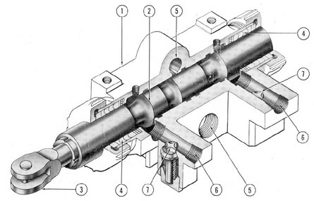
Figure 5-18. Cutaway of rigging interlock.
1) Valve body; 2) spool valve; 3) shackle; 4) packing; 5) ports to tilting lines; 6) ports to rigging lines;
7) check valves.
121
Figure 5-19. Bow plane system in rigging position.
1) Cam on tiller; 2) tilting interlock spool valve; 3) rigging control valve; 4) port, from supply side, after
service line; 5) port, to B-end motor; 6) rigging interlock; 7) tilting interlock; 8) change valve; 9) B-end
motor; 10) drive shaft; 11) clutch handle; 12) bevel gears; 13) rigging gear drive shaft; 14) cam to operate
rigging interlock; 15) worm and gear; 16) clutch to change valve connecting rod; 17) windlass-and-capstan
control valve; 18) windlass-and-capstan control shaft; 19) windlass-and-capstan drive shaft; 20) port, to return side, after service line.
drive shaft (10) whose motion, through the
clutch (11), worm gear, and bevel gears (12),
is transmitted to the rigging gear shaft (13),
thereby rigging out the planes.
Meanwhile, oil from the return port of
the B-end motor passes back through the
change valve, thence through the rigging
interlock (whose spool valve still permits it to
pass), to the return side of the rigging control
valve, and through its return port (20) to the
after return service line. This completes its
cycle from the supply manifold to the return
manifold of the main hydraulic system.
As the planes approach the fully rigged
out position, the rigging interlock spool valve
begins to cut off the flow of oil. The B-end
motor is slowed down and the sector gears are
brought to an easy stop.
f. Operation to dive. Figure 5-20 shows
the direction of flow of hydraulic pressure in
the bow plane tilting system for DIVE. The
pressure side of the line is shown in red, the
return side in blue, the direction of flow is
shown by arrows. Inactive oil is shown in
lighter red.
It is to be assumed that the gear is in the
fully rigged-out position, so that the cam
(8) which moves the spool valve of the
rigging interlock (7) is in a position which will
permit oil from the tilting system to pass.
The handwheel on the telemotor pump (1)
is turned to the right, driving oil out of the
uppermost port of the range valve (2) to
the right-hand side of the control cylinder.
The oil on the opposite side of the control
cylinder passes back through the change valve
to the return side of the telemotor pump,
completing the pressure-and-return cycle in
the low pressure, or control, system.
The movement of oil in the control cylinder
has actuated the bell-crank linkage
connecting the plunger with the control shaft in
the motor-driven Waterbury A-end pump.
When the tilt-box in the motor-driven Waterbury
pump (4) is tilted, its pistons then pump
oil at high pressure through the relief valve
manifold and into the line to the lower end
of the hollow piston rod on the actuating
cylinder assembly (5). This admits oil through
the small ports on the underside of the piston
rod, into the lower side of the cylinder,
causing it to move downward, and tilting the bow
plane (6) to DIVE. Meanwhile, oil is driven
out of the upper side of the cylinder, through
the ports above the piston, thence through
the upper end of the piston rod, into the reline.
From there it passes through the rigging
interlock (7) and back through the opposite
side of the relief manifold into the return
port (the left port) of the motor-driven
Waterbury pump, completing the pressure-and-return
cycle in the high pressure system.
When the bow plane is tilted to RISE,
the flow of oil is in the opposite direction
from that shown in Figure 5-20 and the pressure
side becomes the return side.
g. Windlass-and-capstan clutch and
change-and-control valve. The change-and-control
valve and windlass-and-capstan clutch,
which are structurally associated with the
rigging system, are shown in Figures 5-19 and
5-20. Further examination of Figure 5-19 will
be of help in understanding their function.
The change valve (8, Figure 5-19) serves as a
selector unit for the B-end motor (9),
determining by its position whether the B-end
receives power through the windlass-and-capstan
control valve (17), with which the
change valve is integrally mounted in a single
housing (see Figure 5-21), or through the
rigging control valve (3, Figure 5-19).
The change valve is operated by linkage
from the clutch (11, Figure 5-19), which, like
the change valve, has two positions:
RIGGING and WINDLASS-AND-CAPSTAN.
As the clutch is moved into the required
position, the clutch connecting rod (16),
through linkage, moves the piston in the
change valve (8) into a position which lines
up the ports leading to the B-end motor (9)
with the ports leading to the rigging control
valve (3). Then this valve will operate the
B-end motor to rig the bow planes in or out.
This valve receives its power from the after
service lines.
1. Clutch in RIGGING position. When
the clutch (11, Figure 5-19) is in the RIGGING
position, the rotary motion of the shaft of the
123
B-end motor (9) is transmitted through the
worm and gear (15) to the horizontal drive
shaft (13) which operates the rigging gear.
2. Clutch in WINDLASS-AND-CAPSTAN position.
When the clutch (11, Figure
5-19) is placed in the WINDLASS-AND-CAPSTAN
position, the rotary motion of the
shaft of the B-end motor (9) is transmitted
through the gear box to the horizontal stub
shaft (19) which drives the windlass-and
capstan gear.
At the same time, the clutch connecting
rod (16) moves the piston in the change valve
(8) into a position which lines up the ports
from the B-end motor with the windlass-and-capstan
control valve, through internal channels
inside the change-and-control valve
housing (13, Figure 5-21). The B-end motor
can now be operated by the windlass-and-capstan
control valve (17, Figure 5-19). This
valve receives its hydraulic power from the
forward service lines.
It must be clearly understood that the
clutch handle performs two functions simultaneously:
(1) it connects the drive shaft of
the hydraulic motor either to the rigging gear
or to the windlass-and-capstan gear; (2) it
lines up the change valve either with the
rigging control valve or with the
windlass-and-capstan control valve (17, Figure 5-19). At no
time can the rigging gear and the windlass-and-capstan gear be operated simultaneously,
since the clutch-and-change valve can be in
only one position at a time.
Figure 5-21 shows a cutaway view of the
change-and-control valve. The windlass-and-capstan
control mechanism is seen at the left
of the unit, the change valve mechanism at
the right. The clutch connecting rod (6),
through the lever arm (5), crankshaft (4),
and bell crank (3), moves the change valve
piston (2) to the desired position. When lined
up to permit operation of the windlass-and-capstan
mechanism, controlling is then done
by the windlass-and-capstan control shaft
(10), which extends up to the main deck. This
shaft has a squared end over which a special
T-wrench is placed for operation of the wind
lass-and-capstan gear. The shaft turns the
threaded portion of the nonrising stem (8),
which raises and lowers the sleeve (9), opening
and closing the desired combination of
ports in the control valve, and thereby directing
pressure from the forward service lines
of the main hydraulic system to one side or
the other of the Waterbury B-end motor.
D. OTHER BOW PLANE SYSTEMS
5D1. Bow plane system on earlier classes
of submarines. On earlier classes of submarines,
a bow plane tilting system which differs
in some important details from the one just
described is still being used (see Figure 5-22).
From the diving control stand to the A-end
pump, the older system is the same as the
system described. This includes the controls,
the A-end pump and the motor which drives
it, and the control cylinder.
Here the resemblance ends. In this system
the Waterbury A-end pump delivers oil
under pressure to a Waterbury No. 5 B-end
motor (4), instead of directly to a main cylinder
or ram. The rotary motion developed by
the B-end motor is transmitted through a gear
box (5) to rotate the herringbone gear (6)
clockwise or counterclockwise. The direction
and rate of rotation are, of course, determined
by the angle of the tilt-box in the A-end
PUMP.
Finally, the herringbone gear, which is
meshed with the sector gear (7), turns the
tiller (8) which is attached by a collar to the
plane stocks (9).
On submarines in which this combination
of A-end and B-end Waterbury gears is used
for bow plane tilting, the planes are rigged by
means of an electric motor.
However, the forward windlass-and-capstan
is hydraulically operated also by a combination
of a Waterbury No. 5 A-end and a
No. 10 B-end speed gear. The A-end pump
receives its power from the electric motor
which drives the rigging gear. A clutch directs
the motor power to either the rigging or
the A-end of the windlass-and-capstan, as
124
Figure 5-21. Cutaway of change-and-control valve.
1) Change valve body; 2) change valve; 3) bell crank; 4) crankshaft; 5) lever arm; 6) clutch connecting
rod; 7) windlass-and-capstan control valve; 8) nonrising stem; 9) traveling sleeve; 10) windlass-and-capstan
control shaft; 11) ports to rigging control valve; 12) port to forward service line; 13) internal channels,
from change valve to windlass-and-capstan control valve.
125
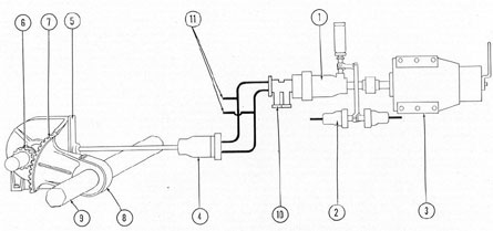
Figure 5-22. Diagram of bow plane system using Waterbury A-end and B-end.
1) Waterbury A-end pump; 2) control cylinder; 3) motor; 4) Waterbury B-end motor; 5) gear box; 6) herring bone gear; 7) sector gear; 8) tiller; 9) plane stocks; 10) relief valve manifold; 17) hand and emergency tilting lines.
desired. Both cannot be operated simultaneously.
A control on the top deck is connected to
the control shaft of the A-end,
enabling the operator to regulate the speed
and direction of the windlass-and-capstan
operation.
5D2. Bow plane system on Electric Boat
Company submarines. a. General arrangement.
On recent classes of submarines built
by the Electric Boat Company the bow plane
system differs considerably from that
described in sections 5C1 and 5C2. The new
system is shown schematically in Figure 5-23.
Its similarities to and differences from the
Portsmouth type are described in following
section.
b. Detailed description. 1. Control units.
Except for minor modifications in appearance,
the main wheel and telemotor pump (1, Figure 5-23),
change valve (2), and emergency
control valve, (4) in the Electric Boat Company
bow plane system are practically identical with
the corresponding installation on
the Portsmouth boats. The rigging, control
valve is also basically the same, in that it
directs hydraulic power from the main
hydraulic system to rig the planes (21) in or
out.
However, there are many important
differences in the two systems.
The most radical departure from the
Portsmouth System is found in the hand
rigging and tilting arrangement. In the Electric
Boat Company system, the bow planes can be
rigged in or out by hand, by the use of the
telemotor pump in the bow plane tilting system.
This requires a special change valve in
addition to the one with which we are already familiar, to direct the power developed
by hand in the bow plane telemotor pump to
either the tilting or the rigging system.
2. Hand rigging and tilting control valve.
This special valve, called the hand rigging
and tilting control valve (8, Figure 5-23), has
three positions, TILT, RIG, and NEUTRAL.
When it is placed at TILT, it allows oil
pressure from the bow plane telemotor pump to
pass to the bow plane tilting cylinder (19).
At RIG, it directs the pressure to the B-end
motor (17) which operates the rigging gear.
At NEUTRAL, both these lines are off.
As a study of Figure 5-23 shows, the hand
rigging and tilting control valve is
mechanically interlocked with the normal (power)
rigging control valve (7) in such a way that
the handle (9) of the power-rigging valve cannot be moved from its own NEUTRAL
position unless the handle (11) of the hand
rigging and tilting valve is at NEUTRAL.
126
Figure 5-23. Bow plane system used in Electric Boat Company submarines, POWER tilting.
1) Telemotor and main handwheel; 2) change valve; 3) emergency control valve handwheel; 4) emergency control valve; 5) motor-driven A-end pump;
6) control cylinder; 7) rigging control valve; 8) hand tilting and rigging control valve; 9) rigging control valve handle, 10) solenoid release handle;
11) rigging-tilting control handle; 12) tilting cut-out; 13) rigging cut-out; 14) bow plane rigging gear; 15) clutch for rigging and windlass-and-capstan;
16) windlass-and-capstan gear; 17) Waterbury B-end motor; 18) windlass-and-capstan control valve; 19) tilting cylinder; 20) piston; 21) bow plane.
127
3. Solenoid locking device. The Electric
Boat Company bow plane system does not
have the hydraulic interlock valves between
the rigging and tilting systems which, in the
Portsmouth system, prevent rigging while the
planes are tilted, or tilting while they are rigged in.
Instead, there is a spring-loaded plunger,
actuated by an electrical solenoid, or magnetic
coil (10), which locks the rigging control
valve in NEUTRAL whenever the planes are
tilted to any degree of rise or more than 15
degrees' dive.
The solenoid is operated by a contact
maker on the bow plane ram (19). When the
planes are anywhere between zero tilt and
15 degrees' dive, the solenoid is closed, or
energized; the plunger is held out by magnetic
force, and the rigging control valve is
unlocked and ready to function. As soon as
the ram has moved, however, to tilt the planes
to any degree of rise, or to more than 15
degrees' dive, the contact maker opens the
circuit to the solenoid, the magnetic coil is
deenergized, and the loading spring snaps the
plunger into the hole, locking the rigging
valve in NEUTRAL, as seen in Figure 5-23.
The solenoid can still be pulled out,
however, by a manually operated electric
push-button on the control panel, which is
itself spring-loaded and will energize the
solenoid only while the operator holds the
button down with his finger.
In the event of failure of the electric
power, the solenoid plunger control as a last
resort be pulled out by hand to allow emergency
operation of the rigging valve.
4. Hydraulic cut-out valves. In the description
of the Portsmouth system of hydraulic interlock
valves, it was explained that
the rigging interlock (Portsmouth design
only) not only controlled the passage of tilting
pressure, but also acted as an automatic
cut-out in the rigging pressure lines themselves
to prevent the rigging gears from
coming against the hard stops at each end
of their travel (see Section 5C2d).
In the Electric Boat Company system,
there are no hydraulic interlocks, but both
the tilting and rigging lines pass through
automatic cut-out valves, similar in principle
to the rigging interlock cut-out feature on
the Portsmouth design. The rotation of the
rigging gears in either direction operates a
pair of automatic cut-out valves (12 and 13)
which, as the rigged-in or rigged-out position
is approached, cuts off the flow of oil in the
rigging or tilting lines.
5. Actuating units. As in the Portsmouth
installation, the bow planes are tilted by the
action of a hydraulic cylinder and are rigged
in and out by a No. 10 B-end Waterbury
speed gear used as a hydraulic motor.
a) Tilting. (See Figure 5-23.) It will be
recalled that, in the Portsmouth boat, the
bow plane hydraulic cylinder arrangement
was somewhat unusual in that the piston was
fixed, while the cylinder moved up and down
over it. However, in the Electric Boat Company
design, the bow plane tilting arrangement
is more familiar-the cylinder (19) is
fixed and the planes (21) are tilted by the
movement of a piston, or ram (20). In
appearance and operation this bow plane ram is
practically identical with the stern plane ram
on the Portsmouth boat.
b) Rigging. The mechanism used for
rigging (14, 15, and 17, Figure 5-23) is practically
identical with that described in connection
with the Portsmouth boats.
c. Operation of Electric Boat Company
system. 1. Tilting by normal POWER.
Figure 5-23 illustrates schematically In the flow
of oils in the Electric Boat Company system
during the operation of tilting to RISE by
normal POWER. As will be seen by a comparison
with Figure 5-20, this operation is
the same as the corresponding operation on
the Portsmouth boat.
Active pressure oil is shown in red,
active return oil in blue; oil in the inactive
parts of the system is shown in lighter red.
Direction of flow is indicated by arrows.
2. Rigging by HAND. Figure 5-24 illustrates
the operation involving the most
radical differences between this system and
the Portsmouth: namely, rigging out by
HAND.
128
Figure 5-24. Bow plane system used in Electric Boat Company submarines, HAND rigging.
1) Telemotor and main handwheel; 2) change valve; 3) emergency control valve handwheel; 4) emergency control valve; 5) motor-driven A-end pump; 6) control cylinder; 7) rigging control valve; 8) hand tilting and rigging control valve; 9) rigging control valve handle; 10) solenoid release handle;
11) rigging-tilting control handle; 12) tilting cut-out; 13) rigging cut-out; 14) bow plane rigging gear; 15) clutch for rigging and windlass-and-capstan;
16) windlass-and-capstan gear; 17) Waterbury B-end motor; 18) windlass-and-capstan control valve; 19) tilting cylinder; 20) piston; 21) bow plane.
129
Active pressure oil is shown in red, active
return oil in blue; oil in the inactive parts
of the system is shown in lighter red. Direction
of flow is indicated by arrows.
The bow plane change valve (2) is set at
HAND.
The handle (9) of the power rigging
valve (7) is at NEUTRAL, locked there by
the solenoid plunger (10).
The handle (11) of the hand rigging and
tilting control valve (8) is set at RIG.
Now the telemotor pump (1) is activated by rotating the main wheel to the right
(clockwise). This sends oil under pressure
through the upper part of the telemotor
pump, through the - change valve and hand
rigging and tilting control valve, and into
one of the rigging lines, which leads to the
Waterbury No. 10 B-end motor (17).
The return oil from the Waterbury motor
follows the same path in reverse, except that
it must pass through the rigging cut-out (13)
on its way back to the change valve and telemotor
pump. As the planes approach the
fully rigged-out position, this cut-out will
automatically shut off the flow of oil in the
circuit, allowing the oil to be bypassed
through a small-sized pipe and throttling
valve which slows down the hydraulic motor.
d. Forward windlass-and-capstan operation.
In this system there is no change valve
for windlass-and-capstan operation. There is
only a control valve (18, Figure 5-23) which
is located in the forward torpedo room. The
windlass-and-capstan receives its power from
the Waterbury B-end motor (17) which
operates the rigging gear. A slide clutch (15)
engages one of the two services it operates.
When one service is engaged through the
clutch, the other is disconnected. A contact
maker on the windlass-and-capstan control
valve handle indicates in the control room
which way the clutch is engaged.
NOTE. 1. Due to the requirement that
the bow planes be rigged out in the specified
time with only one main hydraulic plant
pump in operation, the Waterbury No. 10-B
motor has been replaced by a No. 10-A unit
with provisions for placing the tilt block on
reduced stroke during rigging out, and on
full stroke during rigging in. Since the
power requirement during rigging out of the
planes is not great, the No. 10-A motor is
run at an increased speed during this period
as the displacement per revolution has been
reduced by decreasing the stroke. The other
features of this installation as previously
described remain essentially the same.
2. On later classes of the Electric Boat
Company design, the hand rigging and tilting
control valve has been discarded and the bow
plane change valve has been redesigned to
incorporate the features previously found in
the aforementioned control valve.