|
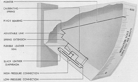
by means of 2 air flow indicators. Each of these
indicators is provided with a scale marked in
cubic feet per minute (Figure 5-8).
Air flow meters are nonelectric and operate
on a difference-of-pressure principle.
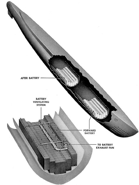
The ends of 2 copper tubes are inserted in
the air stream of the battery ventilation exhaust
line, one tube above, and the other below a
hard rubber baffle.
The tubes are then led to the air flow meter.
The difference in pressure between the tubes is
measured by the instrument and indicated on
a scale in cubic feet per minute of air flow.
The operating unit of the meter consists of
a slack leather diaphragm and a cantilever
spring attached to the scale pointer. The high-pressure copper tube terminates under the diaphragm
and the low-pressure tube enters above
the diaphragm. Difference in pressure determines
diaphragm position and pointer indication.
Due to the delicate nature of the diaphragm,
|
|
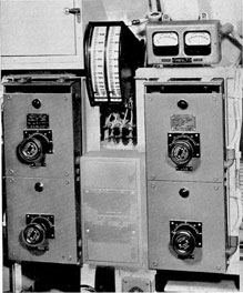
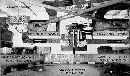
Figure 5-9. Battery ventilation motor controllers, ventilation flow meters, and remote hydrogen detector indicators.
|
|
the instrument must not be subjected to excessive
pressures while in use or when being
cleaned or calibrated.
The zero setting of the indicator pointer is
secured by the zero adjusting screw on the bottom
of the case. This screw should be adjusted
and then locked. If the gage is dismounted, the
zero adjusting screw should be released and, to
avoid damage while handling, the pointer arm
should be secured by a clip accessible through
a handhole in the top of the case. This clip
should be disconnected and the zero adjustment
carefully reset when placing the gage in service.
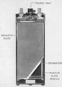
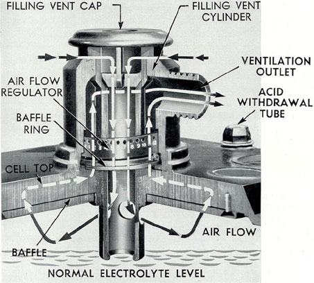
5A8. Air flow through individual cells. The
flow of air through the cells of each battery
compartment is equalized by adjusting regulators.
These are installed as an internal part of
each filling vent cylinder. (See Figure 5-7.)
Proper adjustment of these regulators has been
determined and set at a navy yard and must not
be altered by ship's personnel.
NOTE. Do not permit the soft rubber
nipples to become twisted. A twisted or partially
collapsed nipple will materially affect the
ventilation to the cell.
5A9. Voltmeter. There is an individual cell
voltmeter switch panel for each battery. The
panel for the forward battery is on the bulkhead
at the after end of the wardroom country,
and the panel for the after battery is on the
side of the galley and mess room.
Each panel is composed of 126 jacks
mounted on a phenolic panel and a 0- to 3-volt
voltmeter with a 2-ft cable with plug attached.
In the latest installations an additional 0- to
300-volt voltmeter is also installed. The latter
voltmeter has a switch that can throw it either
across cells 1 to 63, or across cells 64 to 126. It
may also be used for reading grounds on the
battery. (See Sections 3C4 and 3C5.)
Fused voltmeter lead connection boxes are
mounted on the inboard cell connector of each
set of 4 intercell connectors. They are also
mounted on the positive terminal of cell No. 1
and the negative terminal of cell No. 126.
A fused connection box is mounted at both
ends of the intercell connectors at the point
where they connect the end cells, at the end of
the rows in order to eliminate reading the
|
|
voltage drop in the end-of-row connectors.
Separate leads are brought from the fused
connection boxes to special connection boxes.
One of these boxes is mounted on the forward
bulkhead of the forward battery compartment
and the other is mounted on the forward bulkhead
of the after battery compartment. In
Portsmouth-built vessels, the individual leads
are brought up through the deck to the voltmeter
panel without going through a special
connection box.
Four 37-conductor cables connect each special connection
box to its individual cell voltmeter station. Terminal
tubes are used where
these conductors enter the special connection
box and the individual cell voltmeter switch
box.
Each jack is identified by the number of the
cell connected to it. The cell number is engraved
on the phenolic panel, just below each
jack.
The voltmeters are mounted just above the
switch box.
The individual cell voltmeter panels are
provided with enclosing covers which become
data desks when in the open position.
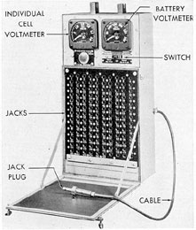
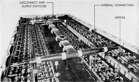
Figure 5-10. Individual cell voltmeter panel.
|