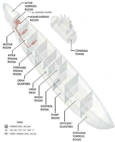
13A1. Description. The engine order indicator system
is composed of 4 rotary transmitter switches and 4
sets of indicating lights in the
maneuvering room, and 2 rotary transmitter
switches with 2 sets of indicator lights in each
engine room. The purpose of the system is to
transmit orders for engine operation between
the maneuvering room and engine rooms.
The circuit designation is 3MB and it is
energized from the ship's 120-volt d.c. supply
taken either from the d.c. bus of the I.C. switch
board, or directly from either the port or starboard
lighting feeder, depending upon the type
of installation.
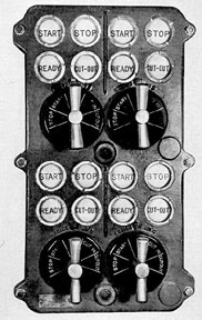
13A2. Operation. The maneuvering room
transmitter unit has a rotary selector switch for
each main engine with positions marked STOP,
START, OFF, CUT-IN, and CUT-OUT. The
4 indicator reply lights in the maneuvering
room for each main engine are marked START,
STOP, READY, CUT-OUT. A push button on
the transmitter operates a bell in each engine
room.
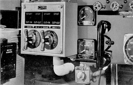
The double indicator in each engine room
has 4 indicator reply lights for each engine.
They are marked START, STOP, CUT-IN,
CUT-OUT. The orders received from the maneuvering
room are shown by this double indicator. In order
that the maneuvering room may
know that orders were correctly received, the
rotary transmitter switch in the engine room is
used to acknowledge orders. This switch is
marked STOP, START, OFF, READY, and
CUT-OUT.
Following is a normal sequence of signals
transmitted in starting an engine:
1. The maneuvering room turns the rotary
switch to START, thereby lighting the START
lamp in the engine room indicator.
2. The engine room acknowledges by turning the rotary switch to START, thus lighting
the START lamp in the maneuvering room indicator.
3. The engine room signals READY to the
maneuvering room. This indicates that the engine
is running and that they are ready to turn
over governor control.
4. The maneuvering room signals CUT-IN, indicating that
they are taking over governor control.
If at any time during the engine's operation,
the engine room signals CUT-OUT, it means
that the engine room desires the load to be removed
from the engine and wishes to have governor control.
The maneuvering room acknowledges the order by
signaling CUT-OUT.
B. LUBRICATING OIL AND ENGINE CIRCULATING
WATER ALARM SYSTEM
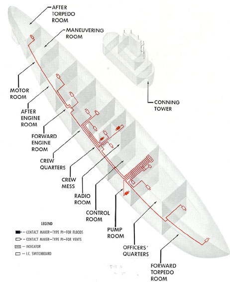
13B1. Description. The lubricating oil (low
pressure) and engine circulating water (high
temperature) alarm system is composed of pressurestatic
and thermostatic contact makers
which under certain conditions close a circuit
and provide an indicating signal.
Pressurestatic contact makers are installed
in the lubricating oil lines to all main engines
and to the auxiliary engine, and in the
lubricating
oil supply between the reduction gears
and main motor bearings.
A pressurestat is essentially an automatic
contact maker consisting of a metal case in
which the lower portion is sealed into an oil
tight chamber by means of a diaphragm. The
upper side of the diaphragm carries the movable
portion of the contact maker. Oil from the line
is led to the lower chamber under working
180
Figure 13-1. Schematic diagram of engine order indicator system.
181
Figure 13-2. Engine order telegraph maneuvering
room transmitter.
pressure, forcing the diaphragm upward against the
tension of a coil spring and holding the contacts
open. If the pressure drops below a set value,
the diaphragm is forced downward by the spring
tension and closes the contacts, energizing a
light and bell circuit. The pressure at which the
pressurestat functions may be varied by adjusting the
spring tension. A pressurestat may be
used either in oil or in water lines.
The thermostatic contact makers are installed
in the circulating water lines leaving
each main engine and the auxiliary engine. They
perform the same function as the pressurestat,
but their contacts are closed by the effect of
heat on a bimetallic strip.
The pressurestatic and thermostatic contact
makers for each main engine are connected in
parallel so that the operation of either one closes
the circuit to a red indicator lamp and a horn
at the engine control station, thus giving an
alarm of an abnormal condition.
The pressurestats installed in the lubricating
oil line between the reduction gears and main
Figure 13-3. Engine order indicator installed on engine gage board.
182
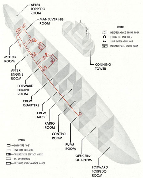
Figure 13-4. Schematic diagram of lubricating oil
flow pressure) and engine circulating water
(high temperature) alarm system.
183
Figure 13-5. Elementary wiring diagram of engine
lubricating oil flow pressure) and circulating water
high temperature alarm system for one engine.
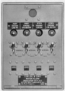
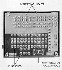
Figure 13-6. Lubricating oil (low pressure) and engine
circulating water (high temperature) alarm panel.
motor bearings operate red indicator lamps and
a horn in the maneuvering room.
A blue lamp at all indicator stations shows
that the circuit is energized. Test cutout
switches are also provided, by means of which
the operation of the light and horn circuit may
be tested.
Power for this system is taken either from
the a.c. or d.c. bus (depending upon the type of
installation) of the I.C. switchboard through a
fused switch. The circuit designation is EC.
184
C. HULL OPENING AND MAIN BALLAST TANK INDICATOR SYSTEMS
13C1. Description. The hull opening and
main ballast tank indicator systems are used to
indicate, by means of lamps, the open or closed
state of the openings in the hull.
Mechanically operated contact makers are
used to operate a group of lamps located on a
panel at the control stations. There are also
mechanical indicators on the outside of the
electrical contact box which provide a local
indication of the position of a valve.
The group of panel lamps has colored glass
covers of red or green mounted over each lamp.
The lighting of these lamps indicates the dangerous
position of the particular hull opening in
red, and the safe position in green, both conditions
being for the submerged condition. A dimmer for all
lights is mounted on the after end of
the indicator panel.
13C2. Hull opening indicator system (circuit TR).
The hull opening indicator system
has contact makers, including mechanical indicators,
installed on the operating mechanism of
each hatch, outboard ventilation, engine induction
and exhaust valve. Each of these contact
makers is connected through a separate 3-ampere fuse
to operate the 2 lamps (in parallel)
for each of the indicator openings.
An additional 10-dial indicator in each engine
room is connected to show the position of
the engine exhaust valves and the ventilation
valves.
On all indicators, red lights show hatches,
doors, engine valves, and hull ventilation valves
not completely closed. Green lights show hatches
actually dogged tight.
Power for the hull opening indicator system is
obtained from the 8-volt secondary of
either of two 120/8-volt transformers, depending on the position of the unfused switch on the
I.C. switchboard. The common terminals of this
switch feed the circuit through a set of 15-ampere
fuses.
Lamps and their fuses in the control room
and engine rooms may be identified by numbers
engraved on the panels.
13C3. Main ballast tank indicator system
(circuit TP). The main ballast tank indicator
system has contact makers, including mechanical
indicators, installed on the operating mechanism
of each main ballast, safety, negative,
and bow buoyancy tank vent valves. All flood
valves and flood valve contact makers are omitted
except those for the safety and negative
tanks. Each contact maker is connected through
a separate 3-ampere fuse to operate the 2 lamps
in parallel for each of the indicator openings.
Red lights show flood valves actually closed
tight and vent valves not completely closed.
Green lights show vent valves that are actually
closed tight and flood valves completely open.
Power for the main ballast indicator system is
obtained from the 8-volt secondary of
either of two 120/8-volt transformers, depending
upon the position of the fused primary switches
for each transformer and the position of an unfused
switch connected to the secondaries of the
transformers. Power is taken from this switch
through a pair of 10-ampere fuses on the I.C.
switchboard.
13C4. Maintenance. Lamps and fuses may
be tested by means of a jumper wire with one
end connected to the circuit terminal screw
provided near the bottom of the fuse panel. The
other end of the wire must be touched to the
top of the fuse for the lamp being tested. If both
lamps for that circuit light, the fuse may be
tested by touching the jumper wire to the bottom
of the fuse clip.
A check for the proper operation of all hull
opening contactors and indicators, followed by
any necessary adjustments, should be made at
the end of every overhaul or upkeep period and
every 2 weeks thereafter.
Ballast tank contactors and indicators on
flood and vent valve operating gear should be
checked at intervals not to exceed 6 weeks and
preferably at the end of the upkeep period. All
mechanical indicators on hull opening valves
should be checked at the same time the electrical
contactors are checked.
185
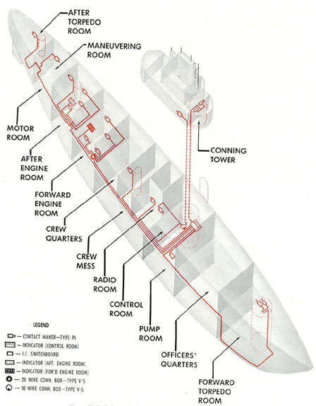
Figure 13-7. Schematic diagram of hull opening
indicator system.
186
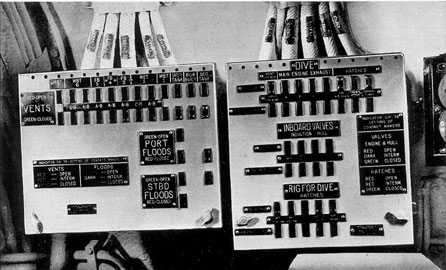
Figure 13-8. On board view of hull opening and main ballast tank indicators.
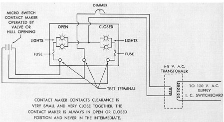
Figure 13-9. Simplified wiring diagram for one unit of
hull opening and main ballast tank opening
indicator systems.
187
Figure 13-10. Schematic diagram of main ballast tank
indicator system.
188
Figure 13-11. Main ballast tank indicator
with cover open.
If contactors contain microswitches, check
the switch pins for freedom of operation.
Contactor rotating parts and contacts should be
inspected for loose electrical connections and
fittings, dirt, burrs, and presence of any foreign
matter. Mechanical linkages should be inspected
for freedom of action, adjustment, and presence
of rust, corrosion, or any foreign material that
might cause faulty operation. Special attention
should be given to checking for poorly fitting
linkage pins, loose or missing cotter pins, and
proper installation of linkages. When there is
backlash in gears or wear in worms, readjustment
is necessary.
The most serious results can be expected
from improper operation either of the contactors
on the hull openings which cannot be sight
checked at rig for diving or of those valves that
normally are not closed until after the first blast
of the diving alarm. These valves include the
hull ventilation valves, the main engine air
induction valves, and the engine outboard exhaust
valves.
13C6. Illumination of hull opening and main
ballast tank indicators. The light from the
indicators installed in the control room is
reduced to a level satisfactory for preserving dark
adaptation by means of rheostats installed in
each system's supply lead. To prevent reduction
of illumination in the instruments installed in
the engine room, which are always under normal lighting,
it has been necessary to install
2-contact split microswitches on openings
whose position must be indicated in the control
room. This results in full illumination of these
indicators at all times. The power supply for
the engine room indicators is not connected
through the rheostats mentioned above. In other
respects, the circuits resemble the simplified
diagram shown in Figure 13-9.
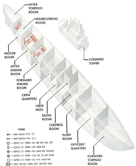
D. RESISTANCE THERMOMETER AND PYROMETER SYSTEMS
13D1. Resistance thermometer systems. a.
Electrical distant reading thermometers are installed
to read the temperatures of various parts
of the propulsion system and auxiliary generator.
They are of two different types: the Brown
Instrument Company type, used to measure
temperatures of the lubricating oil and bearing,
and air temperatures of the propulsion motors
and reduction gears; and the Weston continuous
reading duplex type, used to measure the temperatures
of the bearings and air in the generators and the
lubricating oil and circulating water
in the engines.
b. Brown resistance thermometer. The resistance
thermometer is based on the principle
that the electrical resistance of a metal changes
with the temperature. In the Brown thermometer used
on submarines the system consists of
small coils of resistance wire called bulbs, located
at the points to be measured, and an indicating unit.
The indicating unit contains a selector switch, a
power supply, fixed resistor
units, and a galvanometer calibrated in degrees
Fahrenheit.
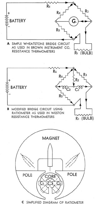
The resistors in the instrument are arranged
to form 3 sides of a Wheatstone bridge circuit
with one of the bulbs selected by the switch
forming the fourth side. Thus a change in resistance
of the bulb causes an unbalance of the
bridge and changes the reading of the galvanometer
(see Figure 13-16).
189
Figure 13-12. Schematic diagram of distant reading thermometer system.
190
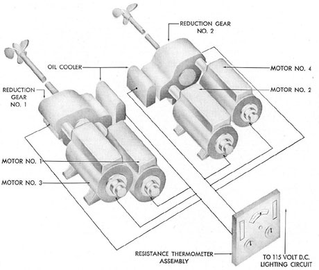
Figure 13-13. Schematic diagram of Brown distant
reading thermometer system for
main motors and reduction gears.
The power supply consists of a transformer
and rectifier for the later vessels and a resistor
and rheostat for dropping the voltage from the
115-volt d.c. lighting system for earlier vessels.
In both types the final input to the instrument
is approximately 8 volts d.c.
c. Weston duplex continuous reading thermometers.
The Weston resistance thermometers used on submarines
depend on the same
principle as the Brown type, with one major
difference: Instead of a simple Wheatstone
bridge and galvanometer, a modified bridge and
an instrument known as a ratiometer are used.
The circuit is shown in Figure. 13-17. R3 is made
equal to R4. Hence it can be seen that the current
in the 2 coils C1 and C2 of the instrument
will be the same when the resistance of R1 equals
the resistance of R5. For any other resistance of
R1, more current will flow in one coil than in
the other. In the instrument, the 2 coils are
mounted on opposite sides of the pivot. A soft
iron circular core threads through the coils. A
permanent magnet yoke with 2 semicircular pole
pieces almost surrounds the moving coils and
core but it is slightly eccentric with respect to
the pivot. This causes the air gap to be smaller
at one side than the other. As currents flow in
the 2 coils connected to produce torque in opposite
directions, they move to such a position
that their torques are equal. Since torque is
determined by the product of the current in the
coil and the magnetic flux across the air gap,
the coil carrying the least current moves to a
191
point in the air gap having greater flux density,
that is, toward the narrow gap. Since the position
of the pointer depends on the ratio between
2 currents rather than on their absolute value,
voltage fluctuations have no effect on the accuracy
of the instruments. In the Weston thermometers, a
separate movement is furnished for
each temperature point, 2 being combined into
a single duplex instrument.
As with the Brown type instruments, the
Weston type also may be either d.c. or a.c., and
the series resistor or transformer and rectifier
are incorporated in the instrument case.
13D2. Brown indicating pyrometers. The
temperature of the exhaust gas from a cylinder
of any diesel engine is a reliable indication of
the load on that particular cylinder.
The exhaust gas temperatures of each cylinder are
obtained with a Brown indicating
pyrometer which makes use of the thermoelectric
principle of dissimilar metals: An electromotive
force is generated in a circuit of 2 wires
of different metals when the 2 junctions of those
wires are at different temperatures. This electromotive
force varies in magnitude with the difference in
temperature between the 2 junctions.
The hot junction is exposed to the temperature
of the exhaust gas, and the cold junction is located
at a galvanometer through which the circuit is closed.
This galvanometer is the indicator and is graduated
in degrees of temperature
corresponding to the voltage generated. Because
the generated electromotive force is zero when
the 2 junctions are at the same temperature,
the galvanometer is adjusted to indicate its own,
or cold junction, temperature when the circuit
is open, or in the OFF position. The galvanometer
automatically varies its pointer position
with changes in the temperature at the hot
junction.
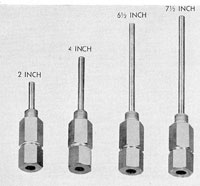
One of the 2 thermocouple wires is made of
pure iron; the other is made of constanten, a
nickel-copper alloy. The wires are welded at the
tip of the thermocouple and mounted in a
closed-end protecting tube of pure nickel. The
protecting tube is fitted with a terminal head
in which the connections are made between the
extension leads and the thermocouple wires.
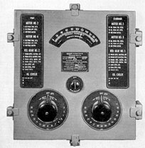
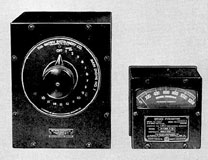
Figure 13-14. Brown distant reading resistance
thermometer indicator and switch panel.
Figure 13-19. Brown pyrometer indicator and rotary
switch for main engine exhaust temperatures.
The indicating mechanism is essentially a
millivoltmeter, calibrated in degrees of
temperature corresponding to the temperature-emf
relationship of the iron-constanten thermocouple.
The galvanometer is, and functions as, a common
direct current instrument except for the
fact that the adjusting screw is used for ambient
temperature setting instead of zero setting.
To obtain the best indication of diesel engine
temperatures, it is necessary to place a
thermocouple tip in the exhaust port of each
cylinder. Some engines also use a thermocouple
at a point in the exhaust pipe system where the
temperature of the combined exhaust gas from
all cylinders can be measured. This point is
called the common temperature.
The Brown pyrometer system includes a
multipoint switch through which the individual
thermocouples are connected to the indicator.
All connections between thermocouples and
the instrument are made with the wires supplied
for this purpose: the iron wire being used for
the positive lead, and constanten wire for the
negative lead. These 2 wires are of the same
material as the thermocouple and cause the cold
junction to be extended from the thermocouple
terminals back to the indicator. No other types
of wire are used for this purpose.
Resistors are provided in the system and
are used for adjusting the resistance of the
external leads to a standard value. The
galvanometer of this instrument is calibrated
for a 15ohm external resistance. The resistor
connections
simply increase the total resistance of the
extension leads to 15 ohms, and this amount
should not be exceeded.
The resistors do not compensate for ambient
temperature changes.
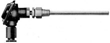
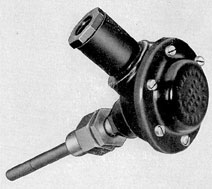
Figure 13-20 Pyrometer unit as installed in engine.
194
13D3. Maintenance. Frequent inspections
must be made to insure that all connections are
tight and free from corrosion. As small voltage
values are used in these circuits, the accuracy
of the instrument depends on perfect contact.
Thermocouples and thermometers usually cannot be
repaired if faulty, but must be replaced.
It is essential, therefore, that a full allowance of
spare thermocouples and thermometers be carried aboard
at all times.
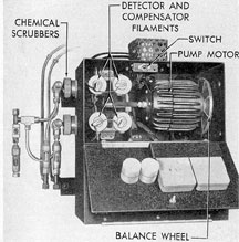
E. HYDROGEN DETECTOR SYSTEM
13E1. Description. There are two types of
hydrogen detectors in service: type N.H.D.,
manufactured by the Cities Service Company,
and type M.S.A., manufactured by the Mine
Safety Appliance Company. The function of the
detectors is to take a sample of exhaust air
continuously from the batteries and indicate the
percentage of hydrogen concentration in the battery
ventilation ducts.
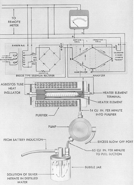
The operation of both types of detectors is
based on the principle of a balanced Wheatstone
bridge circuit. The air sample is drawn,
by means of a motor-driven pump, across one
leg of the balanced circuit where it is caused to
burn with an intensity dependent upon the
amount of hydrogen present. The heat created
heats that leg and increases its resistance,
thereby creating an electrical unbalance in the
entire circuit. The meter connected across the
bridge circuit then shows a deflection, on a properly
divided scale, that is directly proportional
to the percentage of hydrogen present in the air
sample.
In addition to the meter indication, the
M.S.A. type contains a white light connected
in the circuit, indicating normal operation as
long as the hydrogen content is below 3 percent.
When the motor pointer indicates 3 percent on
the scale, a circuit to a red warning light is
closed. This red warning light will remain ON
until it is manually reset. Both meter and light
indications are transmitted to repeater instruments
in the maneuvering room.
The type N.H.D. detector is supplied with
115-volt to 120-volt alternating current directly
from the a.c. bus of the I.C. switchboard. This
system uses a rectifier to convert the alternating
current into direct current for the bridge circuit.
The M.S.A. type detector is supplied with
120-volt direct current from the lighting feeder.
Detailed descriptions of these systems and
specific instructions for maintenance, repair, and
adjustments may be found in the manufacturer's
instruction book pertaining to the particular
type of installation.
195
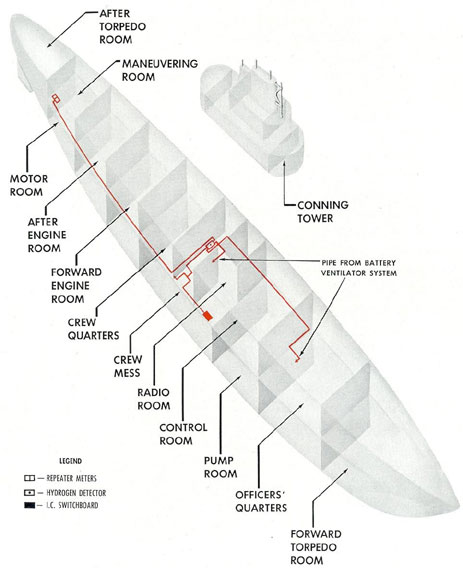
Figure 13-21. Schematic diagram of hydrogen detector system.
196
Figure 13-22. Schematic diagram of Cities Service type hydrogen defector.
197
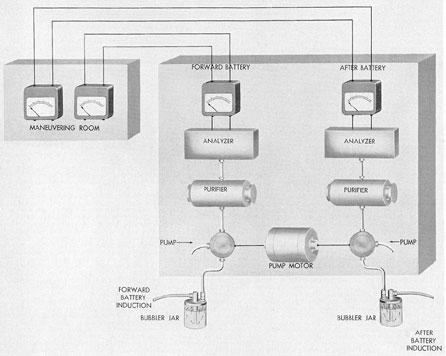
Figure 13-23. Arrangement of units in Cities Service type hydrogen detector.
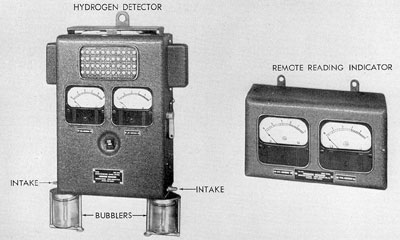
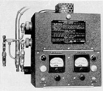
Figure 13-24. Cities Service type hydrogen detector system, master indicator and remote indicator.
198
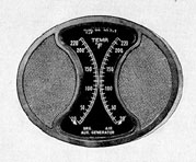
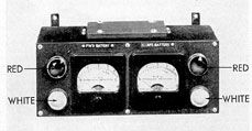
Figure 13-25. M.S.A. type hydrogen detector
remote indicator.
Figure 13-26. M.S.A. type hydrogen detector
with door open.