1A1. Natural magnet. The power of a certain
kind of iron ore to attract iron was first
discovered thousands of years ago. The attracting
power of such ore was named magnetism,
and a piece of ore having this power was named
a magnet.
1A2. Artificial magnet. An artificial magnet
is made by stroking a piece of hard steel or
soft iron with a natural magnet. These pieces
can then be used to magnetize others. However,
the properties of soft iron are such that, although
easily magnetized, it loses its magnetism almost
as soon as the means of magnetizing it have been
removed. Hard steel, unlike soft iron, is more
difficult to magnetize but retains its magnetism.
Hence, soft iron when magnetized becomes a
temporary magnet and hard steel a permanent
magnet. The extent to which these metals retain
their magnetism is an important factor when
they are used in electrical equipment.
1A3. Polarity. If a bar magnet is dipped
into a pile of iron filings, the greatest number
of filings adheres to the ends of the bar. The
ends, where the attraction is strongest, are known
as the poles of the magnet, while the center of
the magnet, where there is no apparent attraction,
is known as the neutral line, or equator.
When this magnet is swung on a thread secured
around its equator, one pole points toward the
north and the other toward the south. The end
which seeks the north is called the north, or
positive pole and the south-seeking pole is called
the south, or negative pole.
1A4. Magnetic attraction and repulsion. If
a bar magnet is suspended from its equator so
that it swings freely and the north pole of another
magnet is brought close to each of its
poles in turn, the north pole of the suspended
magnet is repelled and the south pole is attracted.
If the ends of the suspended magnet
are approached by the south pole of the other
magnet, the north pole of the suspended magnet
is attracted and the south pole repelled. This
power of attraction and repulsion, which all
magnets possess for other magnets and magnetic
fields, is the basis upon which electric motors
depend for their turning motion. It is expressed
in an important law of magnetic attraction which
states: Like poles repel each other and unlike
poles attract each other.
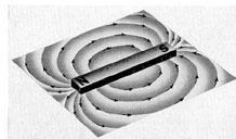
1A5. Magnetic field. When an ordinary bar
magnet is held under a piece of paper on which
fine iron filings are sprinkled, the filings assume
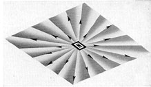
the shape of curved lines (Figure 1-1). Holding
the magnet perpendicular to the plane of the
paper causes the filings to form straight lines
toward the ends of the magnet (Figure 1-2).
The action of the filings indicates the presence
of a force. The space surrounding the magnet
in which this force is apparent is known as its
magnetic field. The lines in which the filings
arrange themselves are called lines of force. The
number of magnetic lines in the field represents
a certain amount of magnetism which is expressed
as a unit of quantity called magnetic flux.
Figure 1-1. Lines of force surrounding a bar magnet.
Figure 1-2. Lines of force surrounding the end of a
bar magnet.
1
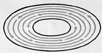
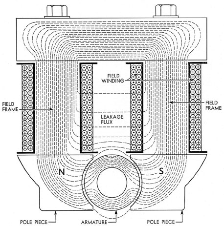
1A6. Magnetic circuits. A magnetic circuit
is the path followed by the magnetic lines of
force of a magnet. A closed magnetic circuit is
one in which the lines of force produce flow
around an unbroken metallic path or ring
(Figure 1-3). Such a ring may be strongly magnetized
and yet have no poles because its lines of
force do not leave the metallic ring comprising
the circuit. Ring magnetic circuits of this type
are used where it is required that little or no
external field be present; for example, in transformers
and certain electrical instruments.
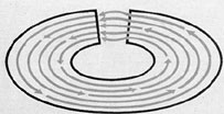
When this ring is cut and opened slightly,
two poles are formed at the cut (Figure 1-4).
This is known as an open magnetic circuit and
is the type used for magnetic circuits of motors
and generators. In the case of a motor or generator
(Figure 1-5), the lines travel from the
north pole piece, across the air gap to the armature,
through the armature core until opposite
the next pole piece, across the air gap, through
the south pole piece through the outside frame
or yoke of the machine, and then to the field
core from which it is assumed they started.
Figure 1-3. Closed magnetic circuit.
Figure 1-4. Open magnetic circuit.
B. ELECTRIC CIRCUITS
1B1. Flow of electricity. An electric circuit
is the closed path through which electricity
moves. For explanatory purposes, the flow of
electricity may be likened to the flow of water.
In each case, the factors of current, quantity
(the rate of flow), pressure (the factor which
causes the flow), and resistance (the factor
which tends to restrict the flow) must be considered.
Electrically these factors are expressed in
the following units:
a. Ampere. The quantity of water flowing
through a pipe is measured by the amount of
water that flows through that pipe in 1 second,
as 1 gallon or 3 gallons per second. Similarly,
flow, or current, of electricity is measured by
the amount of electricity that flows through a
conductor in one second, as 1 coulomb or 5 coulombs
per second. The gallon and coulomb are
units of quantity. The ampere is a rate of flow
equal to 1 coulomb per second. Hence, 25 amperes
means a current flowing at the rate of 25
coulombs per second. The term coulomb is
rarely used because in most cases the quantity
(coulomb) is of secondary importance to the
rate of flow of electricity (amperes).
b. Volt. The quantity of water that flows
through a pipe depends to a great extent upon
the pressure under which it flows. Thus water
pressure is measured in pounds per square inch.
Similarly, the number of amperes, or coulombs
per second of electricity, flowing in a conductor
depends upon the pressure under which the
electricity flows. The electrical unit of pressure
is the volt.
The distinction between amperes and volts
may be expressed as follows: Amperes represent
the amount of current flowing through a circuit;
volts represent the pressure which makes it flow.
The voltage, or pressure difference between two
points in an electrical circuit is sometimes referred
to as the drop of potential or potential
difference.
c. Ohm. The unit of electrical resistance
is the ohm. A wire is said to have a 1-ohm
resistance if a pressure of 1 volt forces a current
2
Figure 1-5. Magnetic circuit of a simple dynamo.
of 1 ampere through it. If the resistance of a
circuit is 2 ohms, the current will be only half
as large and only half an ampere will flow. The
relationship, in direct current, between pressure
(volts), current (amperes), and resistance
(ohms) is expressed as follows: The electric
current in a conductor equals the voltage applied
to the conductor divided by the resistance of the
conductor. This is known is known as Ohm's
Law and may be simply stated as follows:
Amperes = Volts / Ohms or
Ohms = Volts / Amperes or
Volts = Amperes X Ohms
This relationship always holds true when
the quantities expressed are in the same
system. Thus, if the law is applied to an entire
circuit, the number of amperes in the entire
3
circuit equals the number of volts in the entire
circuit divided by the number of ohms of the
entire circuit. If applied to a part of a circuit,
the current in that part of the circuit equals the
voltage across that part divided by its resistance.
It is possible to have a high pressure and
no current. For example, when the path of a
flow of water is blocked by a closed valve, there
is no current, yet there may be a high pressure.
Similarly, if the path of electricity is blocked by
an open switch, there is no current (amperes)
although the pressure (voltage) may be high.
Thus, the amount of current depends upon the
resistance that blocks the path; in this case, the
closed valve or the open switch. The greater this
resistance, the less the current which will flow
under the same pressure.
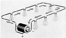
1B2. Series circuit. A series circuit (Figure
1-6) is one in which all the component parts
are so connected that there can be but one path
through the entire circuit in which current can
flow. The resistance of the circuit is the sum of
the resistances of its component parts.
The voltage of a series circuit equals the
algebraic sum of the voltages of its component
parts. Thus, the amount of voltage that must be
impressed on a series circuit to obtain a certain
flow of current can be obtained by first
ascertaining the number of volts required by each
component and then adding these voltages to
find the total voltage required. The current in
a series circuit is the same at all parts of the
circuit.
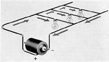
1B3. Parallel circuit. A parallel circuit
(Figure 1-7), sometimes called a multiple or shunt
Figure 1-6. Series circuit.
circuit, is a circuit in which all components are
arranged so that the current is divided among
them. This type of circuit is generally used in
connecting light and power loads. The principal
distinction between the series and parallel
circuits lies in the fact that in a series circuit the
current value is maintained as a constant and
the voltage is adjusted to the load requirements;
whereas in a parallel circuit the voltage remains
constant while the current value varies as more
units, that is, more parallel paths, are cut in or
out.
Figure 1-7. Simple parallel circuit.
C. ELECTROMAGNETISM
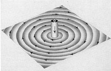
1C1. Magnetic field around a wire. The
relationship between electricity and magnetism,
which is the basis of the operation of nearly all
electrical machinery and measuring instruments,
was discovered by a physicist named Oersted.
He found that a wire carrying an electrical
current exerts an effect on a magnetic needle held
near the wire. This is an indication that a
magnetic field exists around the wire. The existence
of this field can be demonstrated by passing a
wire vertically through a piece of paper on which
fine iron filings are sprinkled. When current
flows through the wire, the filings arrange themselves
in a concentric circular pattern around the
wire (Figure 1-8). The needle of a compass
placed on the paper points in the direction of
the field (shown by the direction of the arrows
in Figure 1-8). When the direction of current
flowing through the wire is reversed, the shape
of the field remains the same, but the direction
of the compass needle is changed by 180 degrees.
The field intensity in both cases depends
upon the strength of the current and the distance
of the compass from the conductor.
4
Figure 1-8. Magnetic field around a conductor.
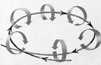
1C2. Solenoid type of electromagnetic field.
When a wire is formed into a single loop and a
current is passed through it, a field exists around
the loop. The intensity of the field varies with
the strength of the current. The field has a north
and south pole and acts in exactly the same
manner as that of a bar magnet. The circular
lines of force around the conductor curl around
it in the same direction, entering at one face of
the loop and leaving at the other (Figure 1-9).
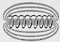
If several turns or loops of wire are wound
to form a loose coil (Figure 1-10), most of the
flux lines produced by each of the turns will
encircle the entire coil instead of encircling only
the turn that generates them. This results in a
field shaped similarly to that around a bar magnet.
A temporary magnet therefore can be produced
by passing an electric current through a
coil of wire. This is known as a solenoid. The
direction of the magnetic flux inside a solenoid
can be found by grasping the solenoid in the
right hand with the fingers pointing in the
direction of the current flow. The thumb will then
Figure 1-9. Magnetic field around a single loop of wire.
Figure 1-10. Magnetic field around a coil of wire.
point in the direction of the magnetic field inside
the solenoid.
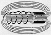
1C3. Electromagnets. A very powerful magnet
can be made by inserting a piece of soft iron
through which a current is flowing into the air
space of a solenoid (Figure 1-11). Such a magnet
is called an electromagnet. The direction of
the lines of force in an electromagnet is the
same as through the solenoid alone but the number
of lines is increased tremendously by the
ability of the soft iron to carry magnetism. The
number of lines produced depends upon the current
passing through the solenoid and the number
of turns or loops in it.
Figure 1-11. Magnetic field around an electromagnet.
In practically all electrical apparatus in
which motion occurs, the motion is produced by
magnetism. The chief advantages of an electromagnet
are: 1) it can be turned on or off; 2 )
the strength can be varied; and 3) the
movements can be controlled by controlling the
current.
5
D. ELECTROMAGNETIC INDUCTION
1D1. General. The operation of motors or
generators is dependent on the principle of
electromagnetic induction discovered by Faraday.
This principle is based on the induction of
an electromotive force (emf) in a wire. An
electromotive force is the force that establishes
the electrical pressure or voltage that will cause
current to flow if the circuit is complete. An
electromotive force can be induced in one of
three ways: 1) by pushing or withdrawing a
magnet through a coil of wire; 2) by winding a
coil around an iron rod, and magnetizing and
demagnetizing the rod by another coil from a
separate current source; or 3) by passing a
conductor through a magnetic field in such a
direction as to cut the lines of magnetic flux.
In the first method, the emf developed is
induced by a change in the number of magnetic
lines threading through the coil. In the second
case, when the separate circuit is closed, a
momentary current is produced which in turn sets
up lines of force to oppose the producing field.
The third case is that of a generator, which is
described in detail below. The emf and current
so produced are called the induced emf and
current.
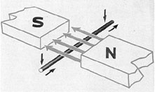
1D2. Principle of the simple generator. If
a conductor is moved downward (Figure 1-12)
so as to cut the lines of force between unlike
poles of magnets, an electrical current-detecting
instrument connected to the ends of the conductor
will indicate that an emf sufficient to
produce a measurable current has been set up
in the circuit.
Figure 1-12. A conductor cutting lines of force.
When the conductor is moved upward, cutting the
lines of force in the opposite direction,
the detector shows a deflection in the opposite
direction, proving that the emf produced is acting
in the opposite direction to the previously
induced emf. The amount of deflection, or the
value of the emf produced, varies with the rate
at which the conductor cuts the lines.
When the conductor is moved horizontally
from pole to pole, no lines are cut, since the
direction of motion is parallel to the lines, and
no deflection is produced. Thus, it is evident
that the direction of the emf produced depends
upon the direction of motion of the conductor.
The value of the emf induced is proportional to
the speed at which the conductor cuts the lines.
The reason for the direction of the motion of
the emf is stated in Lenz's Law as follows:
Electromagnetically induced currents always
have such a direction that the action of the
magnetic fields set up by them tends to oppose the
motion which produced them. This law will
become more meaningful after a study of motor
action (Section 1F1).
The principle of a moving conductor cutting
a magnetic field is applied in the operation of
direct current generators and motors, the conductors
being positioned in slots around the
armature which is rotated between the poles of
electromagnets.
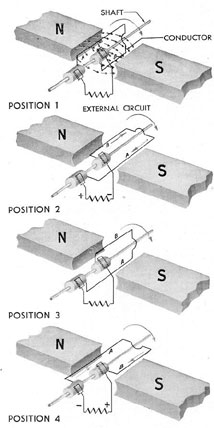
1D3. Generation of an alternating
electromotive force. An alternating emf is produced
by continuously moving the conductor up and
down, cutting the lines of force (see Figure
1-12). A detector in the circuit would indicate
that the emf thus induced tends to cause the
current to flow first in one direction and then in
the other.
Figure 1-13 (reading down) illustrates the
production of a simple alternating emf as a coil
or loop of wire is revolved in a field between
two magnetic poles. The loop consists of two
conductors joined at one end and connected to
two slip rings which are insulated from each
other and from the spindle on which they are
mounted. The circuit is completed by a
resistance known as the external circuit which is
6
connected by sliding connections, called brushes, to
the two slip rings.
If this loop is turned on its spindle so that
the conductor A cuts the lines of force in a
downward direction, and conductor B cuts them
in an upward direction, the emf produced in
the two arms of the loop would be in opposite
directions, but since the two arms are connected
in series, the resulting current flows around the
completed circuit.
In position 1 (Figure 1-13), no emf is produced,
since no lines are being cut, but as the
plane of the loop becomes more horizontal, the
number of lines cut per second increases until
Figure 1-13. The simple alternator in four positions.
the maximum emf (position 2) is produced. As
position 3 is reached, the number of lines cut
decreases until the emf produced is again zero.
As position 4 is reached, the emf again increases
to maximum, but acts in the opposite direction
in the conductors to that shown in position 2
because the conductors are cutting the lines in
the opposite direction. Finally, in position 1, the
emf produced is zero again and the cycle is back
at the starting point.
The current maintained by such an emf is
known as an alternating current and the
arrangement producing it is called an alternator.
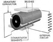
1D4. Generation of a steady electromotive
force. An alternating emf is not suitable for
all forms of electrical work. It is necessary
therefore to produce an emf that has the same
direction constantly. This is accomplished by the use
of a commutator which serves to interchange
the connections between the conductors and
the outside circuit each time the direction of the
emf induced in the conductors reverses. The
commutator is arranged so that the brushes pass
from one commutator segment to the next only
at the points where zero emf is being generated.
A simple two-segment commutator is shown in
Figure 1-14. (A detailed description of a
commutator is given in Section 1E8.)
Figure 1-14. Sectional view of a two-segment
commutator.
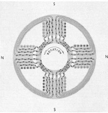
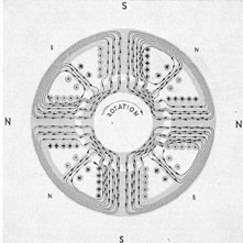
1D5. Multipolar field. Up to this point it
has been assumed that the conductor is in a
magnetic field in which the lines of force are
practically parallel, such as would be found
between a single pair of magnetic poles.
Instead of rotating in such a field, the
conductors usually rotate in a field created by
7
several pairs of poles spaced evenly around the
circumference of a circle. Such a field, produced
by more than two poles, is known as a multipolar field.
In the four-pole field (Figure 1-15), each
conductor goes through a full cycle in half a
revolution instead of in a full revolution as
previously described. As in the case of a conductor
rotating in a two-pole field, when the conductor
reaches a point midway between two adjacent
poles, it is moving parallel to the lines of force
and hence no emf is being generated.
In Figure 1-15 it will be noted that the
direction of current in the field coils is
represented by the symbol (+) on one side and ( . )
on the other side. These may be thought of as
the feathered tail of an arrow (+) disappearing
into the page, and the point of the arrow
( . ) appearing through the page.
Figure 1-15. Multipolar field.
E. DIRECT CURRENT GENERATORS
1E1. Definition. A generator is a machine
used to change mechanical energy into electrical
energy by utilizing the principle of electromagnetic
induction (Section 1D1). The principal
parts of a direct current generator and their
functions are described below.
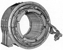
1E2. Field structure. The field structure
(Figure 1-16) consists of the field frame, or
yoke; the field poles, or pole pieces; and the
field coils. The assembly produces the magnetic
field necessary in every generator.
The frame is usually a large ring of formed,
or cast, steel or iron which supports the field
poles and coils in its inner diameter and has
feet on its outer surface to support the machine
on its foundation.
The field poles or pole pieces are constructed
of laminated steel sheets and are bolted around
the field frame. The arrangement of the poles
around the frame is always such that they
alternate in polarity. The ends of the poles may flare
out to increase the surface that faces the
armature, thereby providing better distribution of the
flux. This flared portion also serves to hold the
field coils in place and is sometimes referred to
as the pole shoe.
The field coils are the insulated wire or
strap coils wound around the field poles through
which current is forced to produce the magnetic
field. Two distinct types of field windings known
as shunt and series are used.
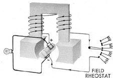
1E3. Shunt generators. In a shunt generator
the field coils are connected in series with
each other and the complete shunt field circuit
is connected in shunt or parallel with the armature
circuit (Figure 1-17). The coils are composed
of many turns of fine wire. The resistance
of the coils is comparatively high, to prevent
the field from taking too much current from the
Figure 1-16. Field frame of a generator.
8
armature circuit. Many turns of wire must be
used in order to obtain the necessary ampereturns which determine the strength of the magnetic
field produced. The voltage produced by
a shunt generator is practically independent of
the current taken by the external circuit.
Figure 1-17. Diagram of shunt generator connections.
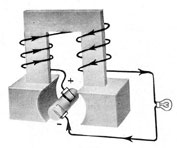
1E4. Series generators. In a series generator
the field is connected in series with the armature
and the external circuit (Figure 1-18). The
coils consist of a few turns of heavy wire having
a low resistance in order to carry the whole
current from the armature to the external circuit.
In a generator of this type, the voltage increases
as the load increases, for when more current is
taken from the machine, more goes through the
field coils, thus causing a stronger magnetic field.
Figure 1-18. Series generator connections.
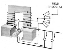
1E5. Compound generators. A compound
generator has both shunt and series fields wound
on the same poles (Figure 1-19). When wound
in such a direction that it helps the shunt field,
the series may be designed to have just enough
strength to overcome the slight decrease in voltage
with increased load of a shunt machine.
When wound in the opposite direction, it may
be designed to give a definite voltage drop with
increased load. This feature is desirable in
certain applications, notably submarine auxiliary
generators.
Figure 1-19. Compound generator connections.
1E6. Methods of excitation. Generators are
termed self-excited when the field coils are
energized by current from the generator itself, or
separately excited when the field coils are
energized by a source outside the generator. Main
propulsion generators on submarines are shunt
wound and separately excited, the current to the
fields being supplied by the battery. The voltage
is controlled through a variable resistance
in series with the shunt field. The voltage, being
dependent on the strength of the field, can thus
be regulated by weakening or strengthening the
field by means of this resistance which is known
as the shunt field rheostat.
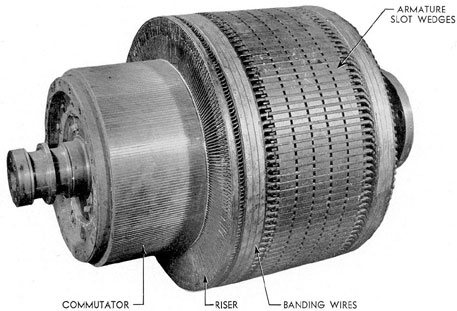
1E7. Armature. The armature (Figure 1-20)
of a generator is composed of the winding in
which the emf is induced and the structure that
supports this winding. This structure is made
up of a number of slotted steel punchings
assembled in the form of a cylinder and mounted
on a spider. The spider is then attached to the
armature shaft. On small machines the armature
laminations may be mounted directly on
the shaft. The windings are shaped to fit in the
slots and are held there by means of wedges
and steel banding wire.
9
Figure 1-20. Generator armature.
1E8. Commutator. The commutator (see
Figure 1-20) is a cylindrical form mounted on
one end of the armature shaft. It performs the
function of changing an alternating emf to a
direct emf. It is built up of a number of
longitudinal segments of copper which are insulated
from each other and from the armature shaft
that supports them. The number of segments
is proportional to the number of coils in the
armature, each of which is connected to the
segments in a sequence determined by the
particular type of armature winding.
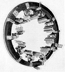
1E9. Brushes and brush rigging. The brushes
bear upon the commutator, collect the current
from the armature winding, and lead it to the
external circuit. The brushes are supported on
holders which in turn are bracket-mounted
around the inner diameter of the brush yoke.
The complete assembly is known as the brush
rigging (Figure 1-21).
The brushes are secured in the rigging in
definite positions around the commutator to
insure sparkless commutation over the range of
loading. Adjacent groups of brushes in large
machines usually are staggered axially so that
the commutator will wear evenly. Provision is
always made to permit rotating the brush rigging
with respect to the commutator in order
to pick up the best plane of commutation. This
provision also permits rotation of the rigging
so that brush holders may be brought to an
accessible spot for maintenance or renewal of the
brushes.
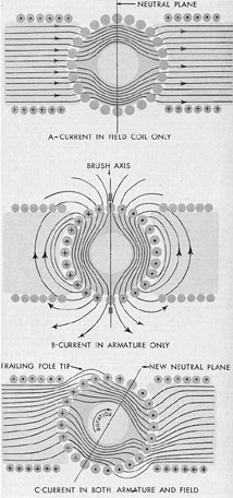
1E10. Armature reaction. The current flowing
in the conductors of the armature sets up a
magnetic field which tends both to weaken and
to distort the main field set up by the shunt field
windings. This effect is illustrated in Figure 1-22
which shows progressively: A, the main field;
B, the field resulting from current in the
armature conductors; and C, the field resulting from
the combination of these two fields. Since the
strength of the field is in part due to the armature
current or load current, the resultant field
C will vary both in strength and position as the
10
Figure 1-21. Generator brush rigging.
load current flowing through the armature
changes.
A requirement of good commutation is that
the brushes short circuit the commutator
segments at a time when there is no induced
current flowing in the conductors to which they are
connected, or, in other words, that the brushes
pass from one commutator segment to the next
when the conductors of the armature to which
they are connected are moving parallel to the
field responsible for inducing the current. This
position is called the plane of commutation, or
the neutral plane. Obviously, this neutral plane
shifts in position with change of load current.
If the machine were to operate at constant speed
and load, and always in the same direction, the
brushes could be shifted to the neutral plane
position and left there with good commutation
thus effected. Such a machine is rarely encountered
and in any case would not meet the
requirements for submarine propulsion.
Since it is impractical to shift the brushes
with each change of load, direction, or speed,
recourse is made to auxiliary fields called the
commutating fields and the compensating windings.
The effect of these fields counteracts the effects
of armature reaction and maintains the
neutral plane in a fixed position throughout the
range of load and speed of the machine, and,
in the case of motors required to run in reverse,
in both directions of rotation.
Figure 1-22. Effect of armature reaction on field
of generator.
1E11. Commutating field windings.The
commutating fields, or interpoles, as they are
sometimes called because of their position relative
to the main poles, consist of a series of
small poles similar to the main field poles in
construction and method of fastening, but
11
having a winding that consists of a few turns of
heavy copper bus bar of high current capacity
and low resistance (Figure 1-23).
The commutating pole windings are all
connected in series with each other and with the
armature circuit. A resistor connected in parallel
with the commutating pole windings is adjusted
and permanently set at the factory to give the
commutating pole strength that results in the
best commutation. Most of the armature
current goes through the commutating pole windings;
only a small amount goes through the
shunting resistor. Since the armature reaction
increases when the armature load current
increases, and the effect of the commutating poles
also increases, the result is that the neutral or
commutating plane is maintained in a fixed
position throughout the load range.
With this method of correction, some
distortion of the field still remains because the
commutating fields, being small, are not
completely effective in correcting the distortion in
the vicinity of the main pole tips. This latter
condition is especially true of the high-power,
compact machines used for submarine propulsion.
Figure 1-23. Effect of commutating field windings.
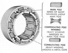
1E12. Compensating windings. To neutralize
completely the effects of armature reaction,
a second set of auxiliary field windings, known
as the compensating windings, is used in high-power
d.c. machines. These windings consist of
a few turns of low-resistance copper bar laid in
slots in the faces of the main shunt field pole
pieces and so connected that the windings carry
current in the reverse direction to that of the
immediately adjacent armature conductors. The
compensating windings are connected in series
with each other and with the armature winding
in a manner similar to the commutating windings
so that they also oppose the field set up
by armature reaction. The current in them is
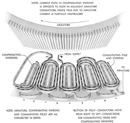
then equal to that in the armature (Figure 1-25).
The field resulting from the compensating
windings is wide in comparison with the commutating
fields but weaker since the flux is less
concentrated. The effect of the two windings
acting in conjunction is to neutralize completely
the effects of armature reaction in respect to
the shifting of the neutral plane, and to eliminate
almost completely the distorting effects.
Thus it is insured that the neutral plane will
remain in fixed position throughout the entire
range of load and speed of the machine, and,
in the ease of a motor, in both directions of
rotation. Good commutation is thus effected
with the brushes located in a fixed position.
Figure 1-24 shows the construction of these fields
and windings.
Figure 1-24. Construction of compensating windings.
1E13. Voltage control. The voltage
produced by a generator is proportional to the
strength of the magnetic field times the speed of
rotation of the armature. The voltage of a shunt
wound generator can be increased in any of the
following ways:
12
Figure 1-25. Currents in armature conductors, compensating windings, and commutating pole windings.
1. Keep the speed constant and increase
the current through the field coils. This increases
the magnetic field and the voltage.
2. Keep the field current and magnetic
field constant and increase the speed of the
engine that drives the generator.
3. Change both the field current and
engine speed in such a way that the product of
the magnetic field times the speed is increased.
Changing the engine speed and field current
in the opposite direction causes the generator
voltage to decrease.
F. DIRECT CURRENT MOTORS
1F1. Principles of operation. An electric
motor is a machine for transforming electrical
energy into mechanical energy. In this respect
it is the reverse of a generator although it is
based fundamentally upon the same general
principles.
In construction, a direct current motor is
the same as a direct current generator. When
a motor is connected to a source of emf as, for
example, a generator, the emf developed by the
generator impels a current through the motor
armature and field windings. Electromagnetic
13
reactions between the fields of the armature and
the main field then cause the motor armature
to rotate and pull its load.
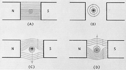
The operation of a motor is based on the
fact that a conductor carrying a current, when
placed in a magnetic field, tends to move at a
right angle to the field. Figure 1-26 (A)
illustrates a magnetic field in which a conductor
carrying no current is placed. In Figure 1-26
(B) the magnetic field has been removed and
the conductor is shown carrying a current in a
direction leading away from the reader. The
current in the conductor has created a
cylindrical magnetic field around it. The direction of
this magnetic field may be determined by the
right-hand rule: Grasp the wire in the right
hand with the thumb pointing in the direction
of the current. The fingers will then point in the
direction of the magnetic field around the wire.
WARNING. Never grasp a real wire when
it is hot. Put your fingers around an imaginary
wire carrying current in the same direction.
magnetic field above the conductor but opposes
it below the conductor. This action creates a
crowding of the flux in the region above the
conductor, and a reduction of the flux density
in the region below the conductor. The crowding
effect of the flux lines creates a force,
comparable to elastic bands under tension and
endeavoring to straighten out. This force exerts a
downward pressure on the conductor; it is
represented in the illustration by the arrow
pointing downward.
When the current in the conductor flows in
the opposite direction to that shown in Figure
1-26 (D), the crowding of the flux lines occurs
below the conductor and tries therefore to force
the conductor upward. This force is represented
by the arrow pointing upward.
1F2. Counter electromotive force. As the
motor armature rotates, an emf is induced in
the armature exactly as in a generator. The emf
induced in the armature is in a direction opposing,
but never as great as, the emf impressed on
Figure 1-26. Force acting on a conductor carrying
current in a magnetic field.
Figure 1-26 (C) shows the magnetic field
obtained by combining the main magnetic field
and the magnetic field created by the current
carrying conductor. The field created by the
conductor acts in conjunction with the main
the armature, causing it to rotate. Since this
emf tends to cause a current in a direction
opposite to that of the current causing the armature
to turn, it is known as the counter, or back
electromotive force. This counter emf is the
14
difference between the impressed voltage and the
product of the armature current times the
armature resistance.
1F3. Starting resistance. The effect of
counter emf is to limit the current in a motor
armature. The armature of a motor, as in a
generator, is of very low resistance in order to
reduce as much as possible current losses in the
machine. When a motor at rest is suddenly connected
to a source of current supply, an abnormally
high current flows in the armature circuit
because the counter emf is not present to
oppose the applied voltage. For example, the
armature resistance of a submarine main motor
is only a few thousandths of an ohm. If a starting
voltage of 250 volts were applied to the terminals,
the current flowing the first instant
would be enormous, resulting in serious damage
to the motor and seriously overloading the generator
supplying the current and the cables and
contactors connecting them.
As soon as the motor starts to rotate, however,
it generates a counter emf which increases
as the motor gathers speed, thereby constantly
reducing the armature current. To avoid this
initial high inrush of current, a resistance is
placed in series with the armature. This resistance
is of such value that when the armature
circuit is first closed, a current value about 1.5
times normal full load current flows. As the
motor gathers speed, a portion of the resistance
is cut out, allowing an increased current to flow
again, thus supplying more torque, or turning
tendency, which in turn speeds up the motor
still more. This process continues until the motor
terminals are connected directly across the
supply line, the current by that time having
been limited to a safe value by the counter emf.
A motor should always be started with a strong
field so that the counter emf may build up as
rapidly as possible and also to provide the
necessary torque.
1F4. Speed control. The most common
method of controlling the speed of a motor is
through variation of the shunt field strength.
This method is based upon the fact that as the
value of the flux is reduced, the motor speed is
increased. The value of the flux is varied by
placing a resistance (rheostat) in series with
the shunt field circuit. Increasing the value of
the resistance in series with the shunt field
decreases the amount of current flowing through
the field, and hence decreases the strength of the
field. Any decrease in the strength of the field
decreases the counter emf in the armature coils
since the counter emf is dependent upon the
number of lines of force cut by the coils on the
armature. It is evident that with a weakened
field, the lines of force cut are fewer and the
counter emf produced is lower. This allows a
greater current to flow from the external voltage,
which in turn causes an increase in the
motor speed.