8A1. Purpose of cooling systems. The
high-speed high-output diesel engines of today
are strictly limited as to the maximum temperature at which they can safely operate. To maintain the temperature below the maximum
allowable limit, various types of cooling systems are used. The thermal efficiency of an
engine would be greatly improved if it were not
necessary to provide a cooling system. The cooling system losses, together with the loss of heat
during the combustion, working, and exhaust
periods, cut down the thermal efficiency of the
engine to a relatively small percentage. Shown
below are the percentages of useful work and
various losses obtained from the combustion of
a fuel oil in a diesel cylinder:
To useful work (brake thermal efficiency)
30-35 percent
To exhaust gases
30-35 percent
To cooling water and friction
30-35 percent
Radiation, lube oil, and so forth
0- 5 percent
There are three practical reasons for cooling an engine:
1. To maintain a lubricating oil film on
pistons, cylinder walls, and other moving parts
as explained in Chapter 7. This oil film must
be maintained to insure adequate lubrication.
The formation of an oil film depends in large
degree on the viscosity of the oil. If the engine
cooling system did not keep the engine temperature at a value that would insure the
formation of an oil film, insufficient lubrication
and consequent excessive engine wear would
result. If the engine is kept too cool, condensation takes places in the lube oil and forms acids
and sludge.
2. To avoid too great a variation in the
dimensions of the engine parts. Great differences between operating temperatures at varying loads cause excessive changes in the
dimensions of the moving parts. These excessive
changes also occur when there are large differences between the cold and operating temperatures of the parts. These changes in dimensions
result in a variation of clearances between the
moving parts. Under normal operating conditions these clearances are very small and any
variation in dimension of the moving parts may
cause insufficient clearances and subsequent
inadequate lubrication, increased friction, and
possible seizure.
3. To retain the strength of the metals
used. High temperatures change the strength
and physical properties of the various ferrous
metals used in an engine. For example, if a
cylinder head is subjected to high temperatures
without being cooled, the tensile strength of the
metal is reduced, resulting in possible fracture.
This high temperature also causes excessive
expansion of the metal which may result in
shearing of the cylinder bolts.
Cylinder heads, cylinder jackets, cylinder
liners, exhaust headers, valves, and exhaust elbows usually are cooled by water. Pistons may
be cooled either by water or oil. In present fleet
type submarine installations, the pistons are
cooled by lubricating oil which is in turn cooled
by engine cooling water. It is important to keep
all parts of the engine at as nearly the same
temperature as possible. This can be accomplished to some extent by engine design. For
instance, the water jacket should cover the
entire length of the piston stroke to avoid
possible unequal expansion of various sections
of the cylinder and cylinder liner.
It requires time to conduct heat through
any substance, therefore the thicker the metal,
the slower the conduction. This is one of the
reasons the size of cylinders in diesel engines is
limited, because the larger the cylinder, the
thicker the material necessary for liners and
cylinder heads in order to withstand the pressures of combustion. Thicker metals cause the
inside surfaces to run hotter, because the heat
is not conducted so rapidly to the cooling water.
8A2. Operation of a cooling system. One
of the principal factors affecting the proper
159
cooling of an engine is the rate of flow of water
through the system. The more rapid the rate
of flow, the less danger there is of scale deposits,
and the formation of hot spots, since the high
water velocity has a scouring effect upon the
metal surfaces of the jackets, and the heat is
carried away more quickly. When the velocity
of the circulating water is slower, the discharge
temperature is higher and more heat per gallon of water circulated is carried away. When
the circulation is speeded up, each gallon of
water carries away less heat and the discharge
temperature of the water drops, resulting in a
relatively cool running engine.
The temperature of the engine can be controlled by the discharge temperature of the
cooling water. This can be done in two ways,
depending upon the arrangement of the piping
and the type of pump used. A common and
simple method is to control the amount of water
pumped, by means of a throttling valve in the
pump discharge to the engine cooling system.
The water can then be made to pass more
slowly through the engine and be discharged
at a higher temperature, or to pass more rap
idly at a lower temperature. If the pump is
driven separately by an electric motor, the same
effect can be obtained by slowing down or
speeding up the pump. The other method to
control the temperature is to bypass some of
the warm discharged water around the cooler
and directly to the suction side of the pump.
This method gives a more uniform temperature
throughout the cooling system and keeps the
passage of water at a higher velocity.
In all modern engines, the latter method
is used and accomplished automatically by
means of a temperature regulator. These regulators may be set to give any desired temperature at the engine outlet. They are used not
only to regulate the fresh water but also to regulate indirectly the temperature of the lubricating
oil leaving the lubricating oil cooler. This is possible because the fresh water that is passed
through the regulator and fresh water cooler is
used as the cooling agent in the lubricating oil
cooler. This permits the maximum amount of
controllability of fresh water and lubricating
oil temperatures with the use of the minimum
amount of equipment.
8A3. Types of cooling systems. Two types
of cooling systems are in common use, the
open system and the closed system. In the open
system the engine is cooled directly by salt
water. In the closed system the engine is cooled
by fresh water and the fresh water is then
cooled by salt water. The closed type of cooling
system is in common use today in all modern
medium- and high-speed diesel engines.
The open type of cooling system has many
disadvantages, the most important being the
exposure of the engine to scale formation, marine growth and dirt deposits in the piping,
and fluctuating sea water temperature. Scale or
deposits not only restrict water flow in the
engine water passages but also act as a blanket
and hinder heat transfer to the cooling water.
This prevents adequate cooling of engine parts
which may result in serious difficulties.
8A4. Open type cooling systems. The term
open system is used because salt water is
drawn directly from sea, passed through the
system, and then discharged overboard.
In a typical system the salt water is drawn
through sea valves and a strainer by a centrifugal pump and then discharged through the
lubricating oil heat exchanger or cooler where
it cools the lubricating oil. The water then
passes to the cylinder liner jackets, exhaust
manifold jackets, exhaust uptake jackets, the
inboard exhaust valve, overboard sea valves,
and to the outboard exhaust valve jackets and
sprays. Part of the water may be piped to the
fuel compensating water system. The remaining
water passes through the muffler jackets and
then overboard.
The open type of cooling system is used
only on engines in the older types of submarines, particularly the O, R, and S classes. All
of the later fleet type submarine engines are
designed with cooling systems of the closed
type.
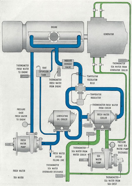
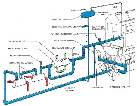
8A5. Closed type cooling systems. Closed
type, or fresh water cooling systems consist
basically of two entirely separate systems-the
fresh water cooling system and the salt water
cooling system. In the fresh water cooling system the same fresh water is reused continuously for cooling the engine. The water is circulated throughout the engine cooling spaces
160
by an attached circulating fresh water pump.
The water is then led to a fresh water cooler,
where it is cooled by the salt water of the salt
water cooling system. After it leaves the cooler,
the fresh water may or may not, depending on
the installation, go through the lubricating oil
cooler to act as cooling agent for the lubricating
oil. The water then returns to the fresh water
pump, completing the circuit.
Fresh water temperature is usually regulated by means of an automatic regulating valve
which maintains the fresh water temperature
at any desired value by bypassing the necessary
amount of water around the fresh water cooler.
An expansion tank is provided which aids
in keeping the fresh water system filled at all
times by keeping available a ready supply of
water. A vent usually is provided in the high
point of the line to keep the system free of air,
thereby preventing the water pump from becoming air bound. The expansion tank also is
equipped with a gage glass by which the level
of water in the tank may be constantly observed. If the level of water in the tank becomes
too low, the system may be replenished from
the ship's fresh water service system through a
make-up line into the suction side of the attached fresh water pump. Any large rapid
fluctuation in the level of water in the expansion
tank signifies some type of leak into or out of
the fresh water system. It usually indicates a
cracked cylinder liner.
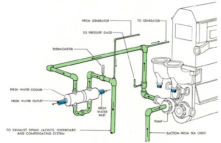
The salt water section of the closed type
cooling system consists of an attached salt
water pump, usually similar to the fresh water
pump which draws salt water from sea through
a sea chest, a stop and check valve, and a
strainer, and discharges it through the fresh
water cooler and then overboard. The overboard discharge performs varying functions,
depending upon the individual installation.
Normally it is used to cool the outboard exhaust
valve, outboard exhaust piping, and muffler.
The ship's compensating water and header box
discharge lines also receive their water from
the salt water circulating water overboard discharge.
On generator type engines the attached
salt water pump furnishes salt water to the
generator air coolers and returns the water to
the overboard discharge. Throttling valves frequently are placed in lines to the fresh water
cooler and generator air coolers to control the
flow of water through these heat exchangers.
Thermometers and pressure indicators are
placed in the system at various places. Salt
water temperatures should not exceed 122 degrees F.
Fresh water temperatures should be between
140 degrees F and 180 degrees F, with a minimum of 140 degrees F
at the engine inlet. Outlet fresh water temperatures should be between 160 degrees F and 180 degrees F.
Cooling water temperatures should not be allowed to drop below 140 degrees F, otherwise excessive
engine wear and corrosion may result if the
temperature drops, below the dewpoint.
8A6. Detached fresh water circulating
pumps. Earlier General Motors and Fairbanks-Morse models (the GM 16-248 and the
F-M 38D 8 and the 9-cylinder 38D 8 1/8) were
equipped only with attached fresh water pumps.
This design made it impossible for fresh water
to be circulated in the engine for cooling purposes after the engine had been stopped. During
normal operations in peacetime this is not too
great a disadvantage because before stopping,
the engine can be idled until it is properly
cooled. During the war, however, emergency
dives were a common occurrence and lack of
a detached pump resulted in very high engine
and engine room temperatures immediately
after diving. This was not particularly good for
the engine and imposed a hardship on engine
room crews, especially in tropical climates.
This condition resulted in the installation in all
new submarines of detached fresh water pumps
for circulation of the water after the engine
has been stopped. An authorized alteration provides for the same installation in older fleet
type submarines.
161
Figure 8-1. Typical fresh and salt water cooling systems.
162
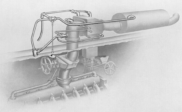
Figure 8-2. Salt water cooling system in superstructure.
163
8A7. Fresh water coolers. The engine
water is cooled in a Harrison type heat exchanger or cooler, similar to the cooler used in
the lubricating oil system. Although coolers used
on various installations may differ in appearance and possibly to some extent in interior
design, their operating principle is identical.
The cooler consists of a tube nest containing a number of oblong tubes fastened to a
header plate at each end to form a core assembly. This assembly is attached to the cooler
casing. The oblong tubes are baffled to form a
winding passage for the liquid to be cooled.
The liquid is cooled as it passes through the
tubes, by the cold salt water (fresh water in
lubricating oil coolers) which enters the casing,
flows between the tubes and is discharged
through the salt water outlet. The cooler is
equipped with zinc plates in the sea water inlet
and outlet passages and at the bottom of the
cooler. These zincs centralize the electrolysis
present in all submarine salt water systems.
Their presence causes electrolytic action to eat
away and disintegrate the zincs rather than the
material of which the cooler tubes are made.
This reduces to a minimum the number of
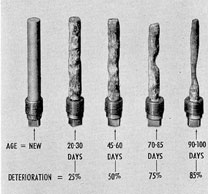
cooler leaks to be expected in submarine installations. Zincs should be examined every 30 days
or oftener where experience indicates the necessity. At each inspection they must be scraped
clean. If this is not done, the efficiency of the
zincs may become negligible and the electrolytic action will work on the tubes. When more
than 50 percent of the zinc has been eaten
away, the zinc should be renewed.
Coolers should be cleaned as frequently as
found necessary to provide an unrestricted flow
of water. In certain types of climate and service, deposits form more rapidly than in others.
Heavy deposits cause an objectionable increase
in pressure drop through the cooler and a consequent decrease in the cooling effect. Chemical
cleanings at regular intervals in accordance
with approved instructions will insure maximum operating efficiency at all times. Wires or
prods which would damage the internal structure of the tubes must not be used in the
cleaning operation. It is a universal rule that
where the installation permits, the liquid to be
cooled enters the cooler at a higher pressure
than the cooling agent. Thus, in a fresh water
cooler the pressure of fresh water should, if
possible, be greater than the pressure of salt
water, so that in case of leaks, the fresh water
will leak into the salt water, a more desirable
condition than leakage of the salt water into
the fresh water system. This is also true in a
lubricating oil cooler wherein the pressure of the
lubricating oil is found to be greater than that
of the fresh water. This prevents water from
getting into the engine lubricating oil if cooler
leaks develop.
8A8. Temperature regulator. The fresh
water in the engine is maintained at a uniform
temperature by the temperature regulator
which controls the amount of fresh water flowing through the fresh water cooler and by bypassing the remainder of the water around the
cooler.
When the fresh water temperature is
higher than the temperature for which the regulator is adjusted, the regulator valve is actuated
to increase the flow of fresh water through the
fresh water cooler and decrease the flow through
the bypass. When the engine water temperature
is lower than the temperature for which the
Figure 8-3. Salt water corrosion of zincs.
164
regulator is adjusted, the valve decreases the
flow of fresh water through the fresh water
cooler and increases the flow through the bypass.
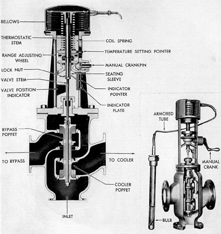
The temperature regulator consists of a
valve and a thermostatic control unit which is
mounted on the valve. The thermostatic control,
unit consists of two parts, the temperature control element and the control assembly.
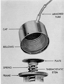
The temperature control element consists of
a bellows connected by a flexible armored tube
to a bulb mounted in the engine cooling water
discharge line. The temperature control element is essentially two sealed chambers. One
is formed by the bellows and cap which are
sealed together at the bottom. The other chamber is in the bulb. The entire system (except
for a small space at the top of the bulb) is
Figure 8-4. Fulton-Sylphon temperature regulator.
165
filled with a mixture of ether and alcohol which
vaporizes at a low temperature. When the bulb
is heated, the liquid vaporizes and increases the
pressure within the bulb. This forces the liquid
out of the bulb and through the tube to move
the bellows down and operate the valve.
The control assembly consists of a spring-loaded mechanical linkage which connects the
temperature control element to the valve stem.
The coil spring in the control assembly provides the force necessary to balance the force
of the vapor pressure in the temperature control element.
Thus, the downward force of the temperature control element is balanced at any point
by the upward force of the spring. This permits
setting the valve to hold the temperature of.
the engine cooling water within the allowed
limits.
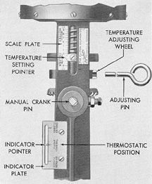
The regulator operates only within the
temperature range marked on the name plate,
and may be adjusted for any temperature within
this range. The setting is controlled by the range
Figure 8-5. Thermostatic control unit.
adjusting wheel located under the spring seat.
A pointer attached to the spring seat indicates
the temperature setting on a scale attached to
the regulator frame. The scale is graduated
from 0 to 9, representing the total operating
range of the regulator.
The temperature regulator can be controlled manually by turning the manual crankpin projecting from the side of the frame. This
operates the regulating valve spring through a
pair of beveled gears and a threaded sleeve. A
pointer, attached to the threaded sleeve, indicates the valve position. When the pointer is
in the BYPASS CLOSED position, the valve is
set to allow all of the fresh water to be pumped
directly through the water cooler. When the
pointer is in the THERMOSTATIC position,
it indicates that the unit is controlled completely by the automatic system as described.
When the pointer is in the COOLER CLOSED
position, it indicates that all of the fresh water
is being bypassed around the water cooler. For
automatic operation the pointer must be set at
the THERMOSTATIC position.
8A9. Fresh water treatment. A treating
compound may be added to fresh water in a
closed cooling system for the prevention of scale
formation and corrosion. This compound, when
added, must be correctly measured in relation to
the amount of water in the system. Too little
will have no effect on the prevention of scale
formation, whereas too much will increase the
corrosion tendencies of the cooling water. The
compound consists of a mixture of six parts (by
weight) of trisodium phosphate and one part
of cornstarch. The mixture must be completely
dissolved in warm water, then added to the
circulating pump suction.
To determine whether the water contains
a sufficient amount of treating compound, a
sample of water is drawn from the system. After
cooling the sample to 85 degrees F or lower, about
10 milliliters of the cooled sample is transferred
to a test tube and one drop of indicator solution, known as corrosion control indicator, is
added. The addition of the one drop of indicator solution will change the color of the sample
water. If the resulting color is yellow, insufficient treatment is indicated. If the color is red,
satisfactory treatment is indicated, and if the
resulting color is purple, it denotes that an
excessive amount of treating compound has
been added.
It should be noted that the addition of the
treating compound is a preventive treatment
only. It will not remove scale deposits already
in the cooling system. If the system is clean
and filled with fresh water only, a test of the
water as outlined above should result in a
yellow color. This indicates that the fresh water
is suitable for use and that it will require the
addition of at least one standard dose of treating compound, consisting of an ounce of treatment per 100 gallons of water, to bring it into
the satisfactory (red) range of the test. If the
color of the same test remains yellow after the
addition of one standard dose, another dose
should be added and this process repeated until
a red color is obtained.
Should the test sample result in a purple
color, about one-fourth of the cooling water
should be drained from the system and replaced
with fresh water. If on retest the purple color
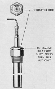
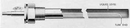
Figure 8-9. Cutaway of thermal bulb.
167
persists, additional water must be drained and
replaced with fresh water. The color of the test
sample must be red. It should never be permitted to enter the purple range.
Anti-freeze solutions. Approved anti-freeze
solutions may be used to obviate the necessity
of draining fresh water systems during freezing
temperatures. The liquid usually used is ethylene
glycol (Prestone). During freezing weather,
all water jackets, cooling chambers, etc., not
filled with anti-freeze solution must be thoroughly drained and blown out one at a time,
using low-pressure air. Proper blowing out of the
water can be accomplished only by closing off
all cooling spaces and emptying them separately.
B. FAIRBANKS-MORSE COOLING SYSTEM
8B1. System piping. The F-M engine is
cooled by circulating fresh water through its
water passages. This water circulates in a closed
system.
The external part of the system consists of
the expansion tank, electrical resistance thermometer, high-temperature alarm contact
maker, fixed orifice, temperature regulator, fresh
water and lubricating oil coolers, and connecting
piping with mercury bulb thermometers and
pressure gages. After performing its engine cooling functions, the water leaves the engine and is
piped to the fresh water cooler. There the fresh
water is cooled by being passed through a large
number of tubes around which cool sea water
flows. After leaving this cooler, the fresh water
is used as the coolant for the lubricating oil
coolers. It is then piped back to the suction
inlet, to repeat its passage through the engine.
A cooler bypass pipe connects the outlet
Figure 8-10. Fresh wafer system, F-M.
168
line from the engine and the suction line to the
pump. An orifice in this pipe permits passing a
predetermined portion of the fresh water directly back to the pump, rather than through
the coolers. This permits cooling of that portion
of water going through the complete part of the
system sufficiently so that it, in turn, can cool
the lubricating oil adequately. From the oil
cooler the water mixes with the uncooled fresh
water, and enters the engine at the desired
temperature.
A bypass pipe is installed across the fresh
water cooler inlet and outlet. Flow of water
through this cooler bypass is controlled by the
automatic temperature regulator. By adjustment
of this regulator, the temperature of the water
can be controlled at the desired point in the
engine under varying operating conditions. Also,
when starting the engine, cold water is quickly
brought up to good operating temperature
range. If the fresh water temperature exceeds a
certain set limit, a high-temperature alarm contact maker, mounted in the line between the
engine outlet and the cooler, closes the alarm
circuit to ring a warning gong.
A small pipe leads from the engine water
header to the expansion tank. Another small
pipe leads from the pump suction line to the
expansion tank. This arrangement enables the
closed system to accommodate variations in
water volume which result from the expansion
and contraction of heating and cooling. Water
is added to the system through the fresh water
filling line from the ship's fresh water system.
Excess water is discharged through the expansion tank vent. The bulb of a continuous reading electrical resistance thermometer is in the
line from the engine to the cooler. The indicator for the thermometer is mounted on the
engine gage board. Between the fresh water
pump and the engine inlet a small tube leads
to the fresh water pressure gage on the engine
gage board. A mercury bulb thermometer is
installed near the inlet to the lubricating oil
cooler, and another on the line from the coolers
to the fresh water pump.
The other pump mounted opposite the
fresh water pump on the engine circulates the
salt water. This pump draws salt water from
the ship's sea chest and forces it through the
Figure 8-11. Salt water system, F-M.
169
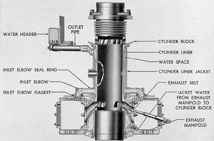
Figure 8-12. Fresh water passage through F-M cylinder.
fresh water cooler and the generator air cooler.
Leaving the coolers, the salt water flows
through the exhaust piping jackets and overboard. A mercury bulb thermometer indicates
the temperature of the salt water, flowing from
the fresh water cooler. From the pump discharge pipe, a small tube leads to the salt water
pressure gage on the engine gage board.
8B2. F-M engine cooling passages. Entering the engine through an inlet in each exhaust
nozzle, the fresh water moves through passages
which surround the exhaust nozzles, and on into
the exhaust manifold water passages extending
the full length of the engine. The exhaust
passages from the cylinder liners and the lower
part of the liner are also cooled by the fresh
water circulation around the exhaust belts. The
water enters from the exhaust manifolds at
openings at the lower side of the belts and
returns to the manifolds at openings at the top.
The water then rises from the exhaust manifolds to pass through an inlet elbow on either
side of each cylinder. These elbows carry the
water to the spaces between the cylinder liner
and its jacket. Cast-in ribs on the cylinder liner
direct the water upward, to cool the liner thoroughly from the bottom. Water passages also
lead to the water jackets on the injection nozzle, cylinder relief valve, and air start check
valve adapters, to cool these units. Upon reaching the top of the cylinder liner jacket, the water
passes out of the cylinder water space through
an outlet pipe which leads to the water header.
This header, rectangular in cross section, extends along the opposite side of the cylinder
block from the control quadrant, just below the
air receiver. Its outlet flange is at the control
end of the engine where it joins the external
part of the system piping.
8B3. Fairbanks-Morse water pumps. The
fresh water and salt water circulating pumps in
the F-M installations are identical centrifugal
pumps. The pumps, mounted on opposite sides
at the control end of the engine, are driven by
170
the lower crankshaft through the flexible drive
which also drives the fuel and lubricating oil
pump and the governor.
The internal construction of the pump at
the impeller end is similar to that of the GM
pump. The pump shaft, however, is supported
on two bearings, a guide bearing near the impeller
end and a thrust bearing at the drive
end. Lubricating oil reaches the bearings from
the control end compartment of the engine
through openings in the pump frame. The oil
is distributed by the bearing spacer on the pump
shaft. Leakage of oil to the outside of the engine
is prevented by an oil seal ring and retainer.
Figure 8-13. Cross section of F-M circulating water pump.
171
C. GENERAL MOTORS COOLING SYSTEM
8C1. System piping. With the exception of
minor differences in the piping arrangement,
the cooling system for GM engines is similar to
that used in F-M engines. The external part of
the closed system is composed of the expansion
tank located at the highest point in the system,
the fresh water and lubricating oil coolers, the
automatic temperature regulator, electrical resistance and mercury bulb thermometers, a
pressure gage at the fresh water pump discharge, and the necessary piping. After circulating through the engine, the fresh water
passes through a temperature regulator before
reaching the fresh water cooler. Water passing
through the fresh water cooler is cooled by salt
water. Part of the water is bypassed around the
cooler and part of it flows through it, depending
on the setting of the temperature regulator. The
water then goes through the lubricating oil
cooler where it acts as the cooling agent. From
the lubricating oil cooler, the fresh water returns
to the suction side of the fresh water pump for
recirculation through the engine. Variations in
water volume resulting from expansion and contraction caused by heating and cooling are controlled by two pipe lines, one extending from
the expansion tank to the suction side of the
pump, the other extending from the expansion
tank to the engine fresh water manifold. A
vent line at the expansion tank keeps the system free of air, thereby preventing the fresh
water pump from becoming air bound, a condition that would result in excessive water temperature.
The salt water pump draws salt water from
the sea chest through a strainer and forces it
through the fresh water cooler and out through
the overboard discharge. A branch line leaving
the main line ahead of the fresh water cooler
supplies salt water to the generator air cooler.
The discharge from the generator cooler joins
the outlet pipe extending from the fresh water
cooler for overboard discharge. The pressure of
the salt water before entering the fresh water
cooler is indicated by a pressure gage and is
controlled by a throttling valve located between
the salt water pump discharge and the fresh
water cooler. A similar valve is used to control
the flow of water to the generator cooler.
The salt water overboard discharge is split
into several parts. Some of the water goes to the
outboard exhaust lines where it circulates
through the exhaust line jacket. This water
then goes through the outboard exhaust valve
for cooling purposes and into the exhaust muffler. Part of this water is sprayed into the
muffler to act as a spark arrester, and the rest
is piped over the side.
Another line from the salt water system
connects into the fuel compensating water line
and to the header box. Most of the water going
into this line is discharged over the side through
the header box, but any water needed to keep
the fuel oil and compensating water systems
filled flows by gravity to the desired tank
through the fuel compensating water line.
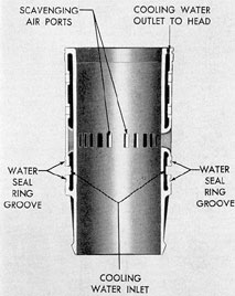
8C2. General Motors engine cooling passages. The attached fresh water pump forces
fresh water to a manifold located in the scavenging air chamber in each cylinder bank. From the
manifolds, the water passes into the cooling
spaces of the cylinder liners by way of a water
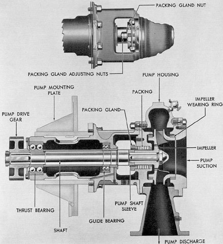
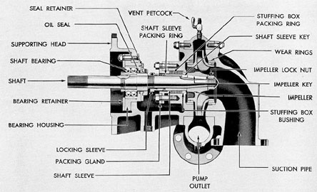
Figure 8-17. Cross section of circulating wafer pump, GM.
connection at the lower deckplate in the engine
cylinder block. The water is then forced upward
into the cylinder heads through ferrules in the
top of the liner, into the water jacket around
the exhaust elbows, and finally into the water
jacket surrounding the exhaust manifold. From
the exhaust manifold, the water enters the external piping leading to the temperature
regulator.
8C3. General Motors water pumps. The
salt water and fresh water pumps used in GM.
cooling systems are of the centrifugal type. The
pumps are mounted on opposite sides of the
blower housing of the engine and are driven by
the crankshaft through the accessory drive gear
train. The principal differences between the two
pumps are in size and capacity. The salt water
pump has a capacity of 560 gallons per minute,
the fresh water pump, 350 gallons per minute.
The following description applies to both pumps.
The principal parts of the pump are the
housing, impeller, drive shaft, and pump supporting head. The impeller is keyed to the
tapered end of the driving shaft and consists of
a number of vanes which throw the water entering at the center of the impeller, outward
through the pump outlet. The impeller rotates
in the housing on two pairs of replaceable wear
rings. A valve sleeve that prevents shaft wear
is keyed to the pump shaft and butts against
the impeller. A small packing ring fitted in a
recess in the end of the valve sleeve provides
a watertight seal. The packing is compressed
between the sleeve and the shaft by a locking
sleeve held in place by a setscrew. When tightening the packing it is first necessary to remove
the packing gland which provides access to the
setscrew. After loosening the setscrew, the locking sleeve can be rotated with a spanner wrench.
The stuffing box packing that surrounds the
shaft sleeve is made up of five rings composed
of a plastic binder impregnated with lead and
graphite. Each ring is about 5 1/16 inch thick.
The pump drive shaft rotates in a ball
bearing that is pressed on the shaft and is supported in a bearing housing inside the supporting head of the pump. The bearing is splash
lubricated from the accessory drive gear train.
A felt seal prevents oil from leaking out of the
housing. Water that may work its way along the
shaft is prevented from reaching the bearing by
a finger locked to the shaft with a setscrew.