5A1. General. Normally, diesel fuel oils for
use in the Submarine Service are purchased by
the Bureau of Supplies and Accounts. At the
time of delivery, the diesel fuel oils are inspected
to make sure that they meet the specifications
set up by the Bureau of Ships. However, emergencies occasionally arise both in the supply
and in the handling of diesel fuels that make it
imperative for operating engineering personnel
to have at least a fundamental knowledge of the
requirements for diesel fuel oil.
5A2. Cleanliness. One of the most important
properties necessary in a diesel fuel oil is cleanliness. Impurities are the prime sources of fuel
pump and injection system trouble. Foreign substances such as sediment and water cause wear,
gumming, corrosion, and rust in the fuel system.
Diesel fuel oil should be delivered clean
from the refinery. However, the transfer and
handling of the oil increase the chance of its
picking up impurities. The necessity for periodic
inspection, cleaning, and care of fuel oil handling
and filtering equipment is emphasized under the
subject of maintenance for each system.
5A3. Chemistry of diesel fuel oil. Diesel
fuel oils are derived from petroleum, more generally known as crude oil. All crude oils are
composed of compounds of carbon and hydrogen known as hydrocarbons. The structure of
the oil is made up of tiny particles called molecules. In crude oil, a molecule consists of a
certain number of atoms of carbon and a certain
number of atoms of hydrogen. The ratio between
carbon and hydrogen atoms in a molecule
determines the nature of the crude oil.
Crude oil is separated into various products
by a process known as fractional distillation. In
general, each product is obtained at its particular
boiling point in the distillation process. The relative order of products obtained, with their
distillation temperature is:
Gasoline-100 degrees to 430 degrees F
Kerosene-300 degrees to 500 degrees F
Fuel oil-400 degrees to 700 degrees F
Lubrication oil-650 degrees F
The fractional distillation process may be
stopped at any point, leaving a residue of a
heavier viscous liquid. This residue may be
cracked in cracking stills by the application of
heat and pressure in the presence of a catalyst.
This cracking process may be controlled so as to
get products of almost any given type of hydrocarbon molecular structure. The products mostly
desired are those that can be used as gasoline
and fuel oil blends.
Fuel oils that meet the specifications for
high-speed diesel engine operation are of two
types, distillate and blended. The distillate type
is obtained by the direct distillation of crude oil
only. Blended type is obtained by blending the
distillate with the residual products from the
cracking stills. As a general rule, distillate fuel
oil is superior to blended fuel oil for high-speed
diesel operation because it possesses better ignition quality, has a lower carbon content, and
contains fewer impurities.
American crude oils are classified into three
types: paraffin base, asphalt base, and mixed
base. These three classifications depend upon
whether paraffin waxes, asphalt, or both remain
after all the removable hydrocarbons have been
distilled from the petroleum.
5A4. Differences in internal combustion fuels.
The two principal types of internal combustion
fuels are gasoline and diesel fuel oil. Both types
are hydrocarbons, but the hydrocarbons differ
radically in their chemical composition.
Gasoline is a fuel adapted to spark ignition,
while diesel fuel oil is adapted to compression
ignition. In spark ignition, the fuel is mixed with
combustion air before the compression stroke.
In compression ignition, the fuel is injected into
the combustion air near the end of the compression stroke. Thus a spark-ignition fuel must
have a certain amount of resistance to spontaneous ignition from compression heat. The
opposite holds true for diesel fuel oils. Entirely
different ignition properties are required of the
two fuels.
5A5. Properties of diesel fuel oils. The
following are the chief properties required of
diesel fuel oils. With the definition of each
91
property is an explanation of its application to
engine operation.
a. The ignition quality of a diesel fuel oil is
the ease or rapidity with which it will ignite.
A diesel fuel with good ignition quality will
auto-ignite (self-ignite) at a relatively low temperature. In simple language the fuel will ignite
quickly and easily under relatively adverse conditions. Thus, where diesel engines must be
started at low temperatures, good ignition quality makes starting easier.
Poor ignition quality will cause an engine
to smoke when operating under a light load at a
low temperature. It will also often cause the
engine to knock and overheat due to the accumulation of fuel in the cylinder between the injection and ignition period. The sudden ignition
of accumulated fuel causes the knock.
There are two widely accepted methods of
determining the ignition quality of a diesel fuel
oil
1. Cetane number test. In this method a
standard reference fuel is used in a test cylinder.
The most widely used reference fuel is a mixture
of cetane and alpha-methyl-naphthalene. Cetane
has an extremely high ignition quality (ignites
quickly) and is rated for the test at 100. Alpha
methyl-naphthalene has a very low ignition
quality (is difficult to ignite) and is rated for
the test at 0.
The single-cylinder test engine used is like
any diesel engine cylinder, except that the compression ratio of the cylinder is adjustable.
Other cylinder conditions, including the delay
period, that is, the interval between injection
and ignition, are held constant. This delay period
is measured by electrical equipment. The fuel to
be tested is used in the test cylinder and the
compression ratio is adjusted until the standard
length delay period is reached. Fuel with high
ignition quality requires a low compression ratio.
Fuel with low ignition quality requires a high
compression ratio.
Next the reference fuel is used in the
cylinder. Using the same compression ratio,
various mixtures or proportions of cetane to
alpha-methyl-naphthalene are used until the
standard length delay period is attained. The
cetane number of the diesel fuel oil tested is
then equal to the percentage of cetane in the
reference fuel that produced the same standard
delay period with the same compression ratio.
For example: if the reference fuel required 60
percent cetane and 40 percent alpha-methyl
naphthalene to produce the same standard delay
period at the same compression ratio as the
diesel fuel oil tested, then the cetane rating of
the diesel fuel oil is 60.
NOTE. The cetane rating for gasoline indicates low ignition quality while cetane rating
for diesel fuel oil indicates relatively high ignition quality. Cetane numbers of diesel fuels in
use today range from about 30 for engines least
critical to fuel to over 60 for the highest ignition
quality fuels.
2. Diesel index. This method of determining ignition quality is obtained by a simple
laboratory test. This test takes into account the
fact that there is a definite relationship between
the physical and chemical properties of diesel
fuel oils and their ignition quality. The diesel
index number method is based on the relation
between the specific gravity of the fuel oil and
the aniline point, which is the temperature in
degrees Fahrenheit at which equal quantities of
the fuel oil and aniline (a chemical derived
from coal tar) will dissolve in each other. To
obtain the diesel index number, the gravity of
the fuel oil, in degrees API, is multiplied by the
aniline point and divided by 100. The result is
the diesel index number of the fuel.
While the diesel index method is accepted
as a fairly reliable method of determining the
ignition quality, the cetane number test is considered more accurate. Hence it is preferable to
use the cetane number test where possible. It
must be remembered, however, that the diesel
index test possesses the advantage of simplicity
and low cost. The normal range of diesel index
is from below 20 to about 60 for diesel fuels in
use.
b. Specific gravity. The specific gravity of a
diesel fuel oil is the ratio of its weight to the
weight of an equal volume of water, both having
the same temperature of 60 degrees F. The specific
gravity of the majority of diesel fuel oils ranges
from 0.852 to 0.934. As a matter of convenience
and to standardize reference, the American Petroleum Institute has established the API gravity scale calibrated in degrees for diesel fuel oil
93
gravities. Lighter weight fuel oils have high
numbers (about 20 degrees to 40 degrees) and heavier weight
fuel oils have low numbers (from 10 degrees up to
about 20 degrees).
Diesel fuel oils are generally sold by volume. Hence the specific gravity of a fuel oil
plays an important part commercially. Knowing
the specific gravity, temperature, and quantity
of a fuel oil, the volume can easily be computed
from standard tables. The specific gravity of a
diesel fuel oil is often referred to, but its significance is frequently overestimated. Efforts have
been made at various times, but with little
success, to establish a definite relationship between gravity and other characteristics such as
viscosity, boiling point, and ignition quality.
c. Viscosity. The viscosity of a fluid is the
internal resistance of the fluid to flow. The viscosity of a fuel oil is determined by the Saybolt
Universal Viscosimeter test. In this test, a measured quantity of the fuel oil is allowed to pour
by gravity through an opening of established
diameter and with the fuel oil at an established
temperature, usually 100 degrees F. The length of time
in seconds required for the given quantity of fuel
oil to pass through the opening determines its
viscosity.
Viscosity is important in diesel fuels because of its effect on the handling and pumping
of the fuel, and on the injection of the fuel.
Viscosity, together with the rate of fuel consumption, determines the size of fuel lines, filters,
and fuel pumps. The efficiency of filtering is
greatly increased in a fuel oil of lower viscosity.
In the injection system viscosity affects the characteristics of the fuel spray at the injection
nozzles. It also affects the amount of leakage
past pump plungers and valve stems, and therefore the lubrication of the various types of
valves and pumps.
d. Heating value. The heating value of a
diesel fuel oil is its ability to produce a specific
Btu output of heat per unit of weight or volume.
There is a definite relation between the gravity
of a diesel fuel oil and the Btu content. The
relationship is approximately:
Btu per pound of fuel = 17,680 + 60 x
API gravity.
It is well to remember that although a
pound of the lighter grades of oils has a higher
heat value than a pound of the heavy oils, a
gallon of the former is generally lower in heat
value than a gallon of the latter. The difference,
however, in the normal range of diesel fuels is
relatively small. For example, a 24 degrees API diesel
fuel has approximately 3 percent greater heating
value per gallon than a 34 degrees API fuel. Considering the many factors related to gravity which
may affect over-all thermal efficiency, the effect
of this difference on fuel economy is usually
negligible.
e. Flash point. The flash point of an oil is
the lowest temperature at which a flash appears
on the oil surface when a test flame is applied
under specified test conditions. It is a rough indication of the tendency of the product to vaporize
as it is heated. The flash point is important primarily with relation to regulations covering
handling and storing of inflammable liquids. It
is of little importance to diesel fuel oil performance. Most diesel fuels have a flash point
well above 180 degrees F. The minimum flash point
required by Navy specifications is 150 degrees F.
f. Pour point. The pour point of a diesel
fuel is the temperature at which the fuel congeals and will no longer flow freely. This is
usually due to the presence of paraffin wax,
which crystallizes out of the fuel at low temperatures. Pour point usually determines the
minimum temperature at which the fuel can be
handled, although in some cases, where there is
considerable agitation preventing the crystallization of wax, the fuel will usually flow at temperatures below the pour point.
g. Carbon residue. The carbon residue of
diesel fuels is usually determined by the Conradson test, in which the fuel is burned in a covered
dish. The carbon remaining is weighed and expressed as a percentage of the fuel. The test
provides a rough indication of the amount of
high-boiling heavy materials in the fuel, and is
particularly useful where, because of high boiling
points, distillation data cannot be obtained. Carbon residue is sometimes taken as an indication
of the tendency of the fuel to form carbon in
the combustion chamber and on the injection
nozzles, although there is a little basis for using
the test for this purpose due to the difference
in the method of combustion used in the test and
that actually encountered in an engine.
94
h. Sulphur content. The sulphur content of
a diesel fuel includes both noncorrosive and corrosive forms of sulphur. If the sulphur content is
high, the copper strip corrosion test should be
made to determine whether or not the sulphur is
in corrosive form. If sulphur in corrosive form is
present, a sample of the oil should be sent to the
nearest laboratory facility for a test to determine
the percentage present. Sulphur in excess of
Navy maximum specifications is likely to damage the engine. When the fuel is burned, the
sulphur is combined with oxygen to form sulphur dioxide which may react with water produced by combustion to form sulphuric acid and
cause excessive cylinder wear. It will also act to
corrode other internal engine parts.
i. Ash content. The ash content of a diesel
fuel oil is the percent by weight of the noncombustible material present. This is determined
by burning a quantity of fuel of known weight
and weighing the ash residue. Ash is an abrasive
material and the presence of ash above the maximum amount allowed by Navy specifications
will have an obvious wearing effect on engine
parts.
j. Water and sediment. The percent by volume of water and precipitable sediment present
in the fuel oil is determined by diluting a quantity of fuel oil with an equal quantity of benzol,
which is then centrifuged, causing water and
sediment to separate. The percentage by volume
is then determined.
The presence of water and sediment is
generally an indication of contamination during
transit and while handling. Fuel containing
water and sediment causes corrosion and rapid
wear in fuel pumps and injectors.
5A6. Engine troubles caused by fuel. As indicated in the discussion of diesel fuel oil
properties, any number of engine troubles may
be caused by unclean or poor fuel oil. Some of
the more common troubles are:
a. Carbon deposits at injection nozzles may
be due to excess carbon residue or excessive
idling of engine.
b. Excess wear of injection pumps and
nozzles may be due to too low a viscosity, excess
ash content, or corrosion from water or sulphur
content in the fuel oil.
c. Exhaust smoke may result when a fuel
with too high an auto-ignition temperature is
used. This is particularly true at light loads
when engine temperatures are low.
d. Combustion knock in a diesel engine is
believed to be due to the rapid burning of a
large charge of fuel accumulated in the cylinder.
This accumulation is the result of nonignition of
fuel when it is first injected into the cylinder, a
condition usually caused by fuel oil of poor ignition quality.
B. SHIPS FUEL SYSTEM
5B1. General. The engineering installation
on present fleet type submarines consists of
four main engines and one auxiliary engine.
These are divided between two engine rooms,
with two main engines in the forward engine
room, and two main engines and the auxiliary
engine in the after engine room. The function of
the ship's fuel oil system is to supply clean fuel
oil to each engine from the ship's storage tanks.
The system may be divided into two parts: 1)
the tanks and their arrangement, and 2) the
different piping systems.
The tanks include normal fuel oil tanks,
fuel ballast tanks, clean fuel oil tanks, expansion
tank, and collecting tank. All of these tanks are
in the spaces between the inner pressure hull
and the outer hull of the submarine with the
exception of the clean fuel oil tanks which are
inside the pressure hull.
The two main piping systems found in the
main fuel-oil system are the fuel oil filling and
transfer line and the fuel oil compensating water
line. These lines connect to the various tanks
and give the fuel oil system a flexibility which
it otherwise would not have.
5B2. The compensating principle. In order
to understand the operation of a submarine fuel
system, it is important to know the basic fuel oil
compensating principle. In a submarine, to assist
in maintaining trim it is necessary to have as
little weight change as possible when fuel is
being used m a fuel tank. Therefore, a compensating system is used which allows salt water
to replace fuel oil as the fuel oil is taken from
a tank. Let us assume that the weight of fuel
95
used is 7.13 pounds per gallon and the weight of
salt water is 8.56 pounds per gallon. Therefore,
when one gallon of fuel is used from a fuel tank,
instead of the submarine-becoming light by 7.13
pounds, it becomes heavy by 8.56 - 7.13 or 1.43
pounds. The submarine, then, becomes heavy as
fuel oil is used. This compensating principle is
used in the normal fuel oil tanks, fuel ballast
tanks, expansion tank, and collecting tank.
These tanks must at all times be filled with a
liquid, either fuel oil, sea water, or a combination of both. The compensating principle is not
used in the clean fuel oil tanks.
5B3. Fuel oil tanks. a. Normal fuel tanks.
The normal fuel tanks are used only for the
storage of fuel oil. They are usually located
toward the extremities of the boat rather than
close to amidships. They vary in size, but normally have capacities of from 10,000 to 20,000
gallons each. Most modern submarines have
four of these tanks. In a typical installation
(Figure 5-1) they are numbered No. 1, No. 2,
No. 6, and No. 7.
b. Fuel ballast tanks. Fuel ballast tanks
are large tanks, amidships, between the pressure
hull and the outer hull, which may be used
either as fuel storage tanks or as main ballast
tanks. They are connected to the fuel oil system
in the same manner as the normal fuel oil tanks,
but in addition, they have main vents, main
flood valves, and high-pressure air and low-pressure blower connections which are necessary
when the tank is in use as a main ballast tank.
When rigged as a main ballast tank, all connections to the fuel oil system are secured.
Most fleet type submarines have three fuel
ballast tanks varying in capacity from about
19,000 to 25,000 gallons. On a typical installation (Figure 5-1), the fuel ballast tanks are
numbered No. 3, No. 4, and No. 5. Current practice is to depart on war patrol with all fuel ballast tanks filled with fuel oil. Fuel is used first
from No. 4 fuel ballast tank, and as soon as that
tank is empty of fuel (filled with salt water) it
is converted to a main ballast tank. Upon conversion, the tank is flushed out several times to
insure that all fuel oil is out of the tank. The
conversion of No. 4 FBT to a main ballast tank
increases the stability of the submarine and
decreases the amount of wetter surface of the
hull when on the surface.
c. Collecting tank. The collecting tank is
one side of a section of tank space between the
inner and outer hulls, the other side being the
expansion tank. This tank has a connection to
the fuel oil filling and transfer line. All of
the fuel used by the engines normally passes
through the collecting tank. A connection from
the top of the collecting tank leads to the fuel
oil meters, fuel oil purifiers, clean fuel oil tanks,
and eventually to the attached fuel oil pumps
on the engines. This tank has a capacity of about
3,000 gallons, and on submarines is located outboard of the forward engine room. The main
function of the collecting tank is to insure that
no large amount of water gets to the purifiers,
clean fuel oil tanks and engine until all the fuel
in normal fuel oil tanks, fuel ballast tanks, expansion tank, and collecting tank has been used.
d. Expansion tank. The expansion tank is
alongside and on the opposite side of the ship
from the collecting tank. It is connected to the
fuel oil compensating water line. It serves two
important functions: first, as a tank to prevent
oil from being blown over the side through the
compensating water line in case of small air
leaks in either the fuel ballast tanks or the normal fuel oil tanks; and second, as a tank to
which oily bilge water may be pumped without
danger of leaving a slick. This tank has a capacity of about 3,000 gallons.
e. Clean fuel oil tanks. The clean fuel oil
tanks, two in number, are used to store oil prior
to its use in the engine and after it has been
purified. These tanks are not compensated with
compensating water. They have capacities of
approximately 600 gallons each.
5B4. Fuel oil piping systems. a. Fuel oil
filling and transfer line. The fuel oil filling and
transfer line extends the length of the ship and
is used for filling the fuel system and transferring the fuel from the various fuel oil tanks to
the collecting tank where it can be piped off,
purified, and used in the engine. There is a connection from the fuel oil filling and transfer line
to the top of each side of each normal fuel oil
and fuel oil ballast tank. This may be a direct
connection or through a manifold, as shown in
Figure 5-1 for normal fuel oil tanks No. 1 and
No. 2. There is also a connection from the fuel
oil transfer line to the bottom of the collecting
tank. This is the line through which passes all
of the fuel from the main fuel oil tanks. At the
forward and after end of the transfer line is a
fuel filling line that connects the forward and
after fuel filling connections on the main deck
with the fuel oil filling and transfer line.
When the fuel system is in use, only one of
the normal fuel or fuel ballast tanks is in service
at a time. This is made possible by a stop valve
in the fuel oil transfer line to the top of each side
of each tank. This valve permits all tanks except
the one in service to be secured on the fuel transfer line.
b.Fuel oil compensating water line. This
line runs the length of the ship and has a connection to the bottom of each normal fuel oil
and fuel oil ballast tank. The salt water that
replaces the fuel oil in the fuel tanks comes from
the main engine circulating salt water discharge
to the compensating water line or, if all engines
are secured, from the main motor cooling circulating salt water discharge to the compensating
line. Most of this water goes over the side by
way of a header box in the conning tower shears,
but the amount of water needed to replace the
fuel oil used goes down into the compensating
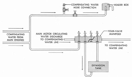
water line by way of a four-valve manifold. The
header box serves to keep a head of water on
the system, insuring that the entire system is
completely filled at all times.
The four-valve manifold is really a bypass
manifold for the expansion tank. The four valves
on the manifold (see Figure 5-2) are used as
follows:
Valve A cuts off the four-valve manifold
from the header box.
Valve B closes the line from the manifold
to the bottom of the expansion tank.
Valve C is the bypass valve for expansion. If this valve is open, the compensating
water an go directly into the compensating
water line without going through the expansion
tank. If the valve is closed, the compensating
water must go into the compensating water line
through the expansion tank. During normal operation this valve is closed.
Valve D closes the line from the manifold
to the top of the expansion tank.
Figure 5-2. Four-valve manifold.
97
Under ordinary operating conditions, all
the valves on the compensating water line to the
individual tanks are locked open and valve C
is locked closed. This is necessary because sea
pressure must be maintained on the inside of the
fuel ballast tanks, normal fuel tanks, expansion
tank, and collecting tank, when the submarine
is submerged. If this were not done, the sea
pressure on a deep dive would become so great
as to cause a rupture of the relatively weak
outer hull. Therefore, it is vital that all the
valves mentioned above be open or closed as
indicated. If these valves are properly rigged
when the submarine is submerged, sea pressure
can enter the system through the header box
and then go to the inside of every fuel oil tank
except the clean fuel oil tanks, if the valves on
the compensating water branch lines to each
tank are open. These valves on the individual
branch lines are also normally locked open. This
maintains the same pressure on each side of the
submarine outer hull, insuring that it will not
rupture. The valves are always locked to prevent
accidental closing or opening.
5B5. Operation of the system. When the
submarine is departing on war patrol, all tanks
in the fuel oil system are completely filled with
fuel. Upon departure, one of the normal fuel oil
or fuel ballast tanks will be on service. As soon
as fuel is drawn from the top of the collecting
tank by means of the fuel oil transfer pump, salt
water comes into the bottom of the expansion
tank, keeping the system completely filled with
liquid.
The path of the water can be traced by
referring to Figure 5-1: Assume that No. 4 FBT
is in service. As fuel is taken off the top of the
collecting tank, fuel comes from the top of No.
4 FBT through the fuel oil filling and transfer
line into the bottom of the collecting tank, replacing the fuel taken from the top of that tank.
At the same time the fuel taken from the top of
No. 4 FBT is replaced by the fuel from the top
of the expansion tank by way of the four-valve
manifold, the compensating water line, and the
compensating water branch line to the bottom of
No. 4 FBT. The fuel oil drawn from the top of
the expansion tank is replaced by salt water
entering the bottom of the expansion tank by
way of the four-valve manifold and the line to
the header box. It must be emphasized that all
the above operations are taking place concurrently and that the entire movement of the
liquids is caused by the head of water on the
system from the header box.
As soon as the expansion tank is filled with
salt water, the salt water comes up to the four-valve manifold through valve D into the compensating water line, and thence into the bottom
of No. 4 FBT. As soon as No. 4 FBT is empty
of fuel, salt water rises into the fuel oil transfer
line and then into the bottom of the collecting
tank. This is a positive indication that the No.
4 FBT has no more fuel in it. In order to tell
when the salt water reaches the collecting tank,
a liquidometer age which reads directly the
amount of fuel in the tank is placed on the collecting tank. As soon as this gage reads less than
completely filled, it is evident (in this case) that
No. 4 FBT has no more fuel. No. 4 FBT is then
secured on the fuel transfer line and another fuel
tank is placed on service. The small amount of
water may be left in the bottom of the collecting
tank, as fuel oil that comes into the tank will
rise through the water to the top of the tank.
The water normally is left in the bottom of the
collecting tank until the ship is refueled. At that
time the water is withdrawn by pumping it out
with the drain pump through the drain line to
the bottom of the collecting tank.
5B6. Blowing and venting of fuel tanks.
Each side of each tank is provided with blow
connections which connect to the ship's low-pressure 225-pound air line. In an emergency or
to effect repairs, it is often necessary to blow a
fuel tank completely clear of all liquids. This is
done by closing the tank's stop valves to the
fuel oil transfer line and blowing the fuel or
water over the side or to another tank (through
the compensating water line).
The air line from the blow valve to the
tank also has a connection to permit venting of
the tank if some air has accumulated in its top
or if it is desired to fill a completely empty tank
with oil or water. All fuel tanks are equipped
with either liquidometer gages or sampling
cocks. These sampling cocks are used to take
samples of liquid at various fixed levels in the,
tank in order to ascertain approximately the
98
amount of fuel in the tank. The liquidometer
gages are adjusted so as to read directly the
number of gallons of fuel in the tank.
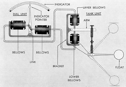
5B7. Liquidometers. In submarine fuel systems, liquidometers are used to determine:
1) the level of oil in partially filled tanks,
such as clean fuel oil tanks, and
2) the level between fuel oil and salt water
in completely filled tanks such as normal fuel
tanks, fuel ballast tanks, collecting tank, and
expansion tank.
The liquidometer is equipped with a float
mechanism, the movement of which activates a
double-acting opposed hydraulic mechanism
which registers upon a properly calibrated dial
the volume of oil in a tank in gallons.
The float of a liquidometer used in compensated fuel tanks is usually filled with kerosene to a point where it will float in water but
sink in fuel oil. Since the water is below the oil,
the float will sink through the oil and stop at
the compensating water level.
The instrument consists essentially of two
units, a tank unit located in the tank whose
capacity is to be measured, and a dial unit
located at some distant point away from the
tank (such as in the control room of a submarine). Operation of the instrument is dependent upon the movement of the float in the tank
which is mechanically connected to an upper
and lower bellows of the tank unit. These two
bellows are rigidly supported at one end by a
bracket, and both are connected by tubing to
two similar bellows in the dial unit. The dial
unit bellows are each supported at one end by a
bracket which also provides a bearing connection for the indicator pointer. The free ends of
the bellows, facing the pointer, are connected to
a link which actuates the pointer. When the float
moves down, the mechanical linkage between
the float arm and the upper and lower tank
bellows compresses the lower bellows, forcing a
portion of the liquid from it into the interconnected dial unit bellows, causing it to expand.
At the same time, the upper bellows in the tank
unit is being elongated through the mechanical
Figure 5-3. Schematic diagram of liquidometer.
99
connection to the float arm and takes in a portion of the liquid from the other dial unit bellows, which is then caused to contract. Reverse
action takes place if the tank float moves upward.
5B8. Maintenance of ship's fuel system. All
fuel storage tanks should be periodically inspected and cleaned. This is usually done during
submarine overhauls at naval shipyards.
All screen strainers used in connection with
the fuel oil system should be periodically removed and cleaned.
The valve seat gaskets used in the fuel ballast tanks are made of special, oil-resisting rubber. These gaskets should be inspected at each
filling and replaced if deteriorated or damaged.
In the fuel ballast tanks, all valves are enclosed in galvanized wire mesh screens. These
wire mesh screens should be cleaned whenever
inspection indicates that it is necessary. On some
submarines, the connection between the compensating water line and the four-valve manifold
is provided with a plug protected sight glass to
check the pipe's contents. This glass should be
kept in clean and readable condition at all
times. In most modern fleet type submarines this
sight glass has been blanked off because of possible breakage during depth charge attack.
It is essential that all air be excluded from
the fuel system, or the system may become air-bound, thus preventing proper flow of oil to the
engines and also disturbing the trim of the submarine. This may be done by venting the system
through the vent facilities provided.
In venting fuel tanks in use, the following
order should be observed: first, the expansion
tank, then the fuel tank on service, then the
collecting tank. The remaining fuel tanks may
then be vented in any order. The discharge line
from the collecting tank to the clean fuel oil
tank should be closed during venting operations.
C. SUPPLY FROM SHIP'S FUEL SYSTEM TO ENGINE FUEL SYSTEMS
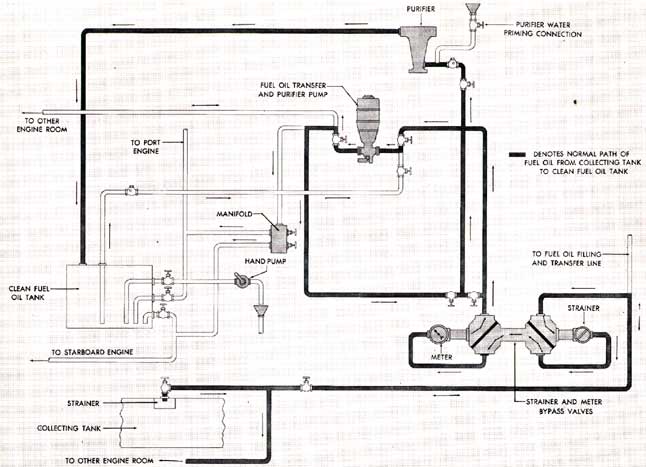
5C1. General. After leaving the collecting
tank, fuel is piped through a system comprised
of strainers, fuel meters, fuel oil transfer pumps,
purifiers, and clean fuel oil tanks before reaching the engine. This section of the fuel oil system is divided into two parts. One part serves
the forward engine room, the other the after
engine room. The two are interconnected to provide flexibility of operation.
5C2. Strainers and meters. Fuel oil to be
used in the engine is normally taken from the
top of the collecting tank. It may, however, in
some installations, be drawn directly from the
fuel oil filling and transfer line. In either case,
the oil should go through a wire mesh type
strainer and fuel meter before entering the suction side of the fuel oil transfer pump. Both
strainer and meter are fitted with bypass connections by means of which a strainer, or meter,
or both may be bypassed.
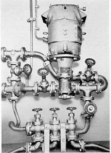
5C3. Fuel oil transfer and purifier pumps.
Located in each engine room is a positive displacement type fuel oil transfer and purifier
pump, driven by an electric motor. The primary
function of this pump is to transfer fuel oil from
the collecting tank to the clean fuel oil tank
through the purifier. It may also be used for
priming purposes by taking a suction from the
clean fuel oil tank and delivering the priming
oil to the individual engine fuel system. An engine normally is primed before starting, particularly if it has been secured for some time.
Under normal operating conditions this
pump is operated until the clean fuel oil tanks
are full. It is then secured until the level of oil
in the clean fuel oil tanks becomes such as to
indicate need for replenishment.
5C4. Pure oil purifiers. a. General. The fuel
oil purifiers are Sharples centrifuge units which
operate on the principle of centrifugal force.
Centrifugal force is the force exerted upon
a body or substance by rotation that impels that
body or substance outward from the axis of
rotation. When a mixture of liquids is revolved
at high speed in a container, the centrifugal
force causes the components of the liquid to
separate. The component with the greatest specific gravity will assume the outermost position,
and the lightest component, the innermost position. Thus, if a mixture of water and oil is
revolved, the water, being the heavier component, will separate from the lighter oil and form
100
Figure 5-4. Fuel oil supply from ship's fuel system to engine fuel system in one engine room.
a layer around the wall of the container, while
the oil remains near the center of the container.
The Sharples fuel oil purifier operates on this
principle.
The Sharples purifier can be used as a
separator or a clarifier. When used as a separator, the purifier separates oil from water and
solid sediment. When used as a clarifier, it
separates oil from solid sediment only. The unit
is usually set up as a separator in fuel oil systems and a clarifier in lube oil systems. (See
Section 7B7.)
b. Operation. The fuel oil transfer and
purifier pump forces fuel oil through a short
connecting line at the bottom of the purifier
bowl. The purifier bowl is revolved by an attached electric motor at about 15,000 rpm. A
three-wing partition extends the full length of
the bowl on the inside. The purpose of this
partition is to keep the liquid in the bowl revolving with the bowl. Otherwise there would be
slippage of the liquid column which would
reduce the effect of the centrifugal force.
When the machine is operated as a separator, the bowl is primed with fresh water until
an effective water seal is created at the water
discharge outlet. The water priming line is
sealed off from the fuel inlet line by means of a
check valve which prevents water from finding
its way into the fuel system. Then the fuel oil
supply is forced into the swiftly revolving bowl.
The centrifugal force throws the water, which
has a heavier specific gravity than the oil, to the
outside wall of the bowl and creates a vertical
layer of water at this outer extremity. The fuel
oil, which has a lighter specific gravity, forms a
layer next to the water. Any particles of sediment in the fuel oil have a heavier specific
gravity than either the water or oil and are
drawn and held against the wall of the bowl by
the centrifugal force. Dirt and sediment are
cleaned out of the bowl when necessary.
At the top of the purifier bowl is a barrier
called a ring dam, which covers the top of the
101
Figure 5-5. Fuel oil transfer and purifier pump.
vertical column of water and fuel oil. There is
an opening at the outer diameter of the ring dam
through which only excess water is discharged.
At the inner diameter of the ring dam is another
opening through which only purified fuel oil
discharges. Thus, as long as the centrifugal force
and the effective water seal are maintained, it
is impossible for fuel oil to displace the water
and get out through the water discharge opening. It is just as impossible for water to get out
through the fuel oil discharge opening as long as
the centrifugal force is in effect.
5C5. Clean fuel oil tanks. All fuel oil supplied to the engines is normally drawn from the
clean fuel oil tanks. There are two clean fuel oil
tanks, one in the forward engine room and one
in the after engine room. Under normal operating conditions, the engines in each compartment
draw their supply from the clean fuel oil tank
in that compartment.
Each tank averages about 600 gallons
capacity in fleet type submarine installations.
By means of a system of valves and piping, fuel
Figure 5-6. Attached fuel oil supply pump, F-M.
oil can be pumped to either fuel oil purifier by
means of the transfer and purifier pumps and
discharged to either clean fuel oil tank. Also,
the transfer and purifier pump may be used to
draw fuel oil from either clean fuel oil tank
and supply any engine directly, during priming
operation.
A hand pump is connected to the clean
fuel oil tanks to provide a means of checking
the contents of the tank for water, for testing
the quality of the oil, and for removing residual
oil in the tank when it is desired to clean it.
Each engine in a compartment is connected
to the clean fuel oil tank in the same compartment by a fuel line which goes from the bottom
of the clean fuel oil tank up to the attached fuel
oil pump on the engine. The attached fuel oil
pump takes a suction from the clean fuel oil
tank and delivers the oil to-the engine fuel system. If the attached fuel oil pump on one engine
should become inoperative, it is possible to
connect the fuel oil transfer and purifier pump
so as to supply fuel up to the engine, thereby
preventing a shutdown of the engine.
102
Figure 5-7. Exploded view of attached fuel all supply pump, F-M.
Each clean fuel oil tank is equipped with a
liquidometer to measure the quantity of fuel oil
in the tanks at all times.
5C6. Attached fuel oil supply pump, F-M.
The attached fuel oil supply pump (Figures
5-6 and 5-7) draws fuel by suction from the
clean fuel oil tank and delivers it through the
strainer and filter units to the engine main fuel
oil header.
The pump is a positive displacement type
gear pump and is driven directly from the lower
crankshaft of the engine through a flexible gear
drive. A packing gland is provided on the fuel
oil pump drive gear shaft to prevent fuel oil
from leaking out around the shaft.
5C7. Attached fuel oil supply pump, GM.
The function of the GM attached fuel oil supply
pump is the same as that of the pump described
in section 5C6 above. This pump is also of the
positive displacement type, but it is driven
directly from one of the engine camshafts instead
of the crankshaft as on the F-M engine.
The pump drive shaft is provided with a packing gland to prevent fuel oil from leaking around
the shaft.
Fuel oil is drawn from the clean fuel oil
tank by suction created by the pump and fed
into the pump housing through an inlet at the
top of the pump. Oil is forced from the outlet at
the bottom of the pump into the engine supply
line. A pressure regulating valve in connection
with the pump may be set to maintain a pressure of 40-50 psi in the engine fuel system. A
pressure relief valve may be set at slightly above
the desired pressure to bleed off excess fuel oil
when the pressure exceeds the maximum setting.
This oil returns to the clean fuel oil tank.
5C8. Duplex fuel oil strainer. All fuel oil
delivered to the engine fuel header by pressure
from the attached pump must pass through a
duplex type strainer. This strainer actually consists of two strainer elements which may be
used either individually or in pairs. The flow of
fuel oil through either or both strainers is controlled by a manually operated valve. When the
valve is set to bypass one strainer, the bypassed
element may be removed and cleaned without
disturbing the flow of fuel oil to the engine.
Figure 5-9. Fuel oil filter.
Each strainer consists of a body or case
which is fitted with a metal ribbon wound element. A scraper device with long blades that
contact the inside surface of the element is fitted into each strainer. A handle for turning the
element extends through the top of the strainer
so that the operator may occasionally turn the
element, thereby cleaning accumulated dirt
from the surface of the element. Dirt and sediment drop to the bottom of the case and
should be removed at regular cleaning periods.
Each duplex strainer is equipped with a
duplex pressure gage which measures the pressures of the fuel oil fed into the strainer and of
the oil leaving the strainer. A drop of 10 psi between the inlet pressure and the outlet pressure
indicates that the element or elements of the
strainer needs cleaning. Each strainer has a
small valve at the top of the case for venting air
from the unit.
5C9. Duplex fuel oil filter. Most installations are equipped with duplex fuel oil filters as
well as strainers. In function and operation the
104
filters are similar to the strainers. In the duplex
filter, the element is a removable absorbent type
cartridge which is removed and thrown away
when it becomes dirty. The absorbent type filter
cartridge is a denser element than the strainer
element and consequently filters out finer
particles of dirt and foreign matter. The filter elements are not equipped with scrapers. They
should be examined when the pressure registered by the duplex pressure gage drops a specified
value. If found dirty, they must be removed and
replaced by a new element.
D. FUEL INJECTION SYSTEMS
5D1. Basic requirements of a fuel injection
system. The primary function of a fuel injection system is to measure accurately, vaporize,
and inject the fuel at the proper time according
to the power requirements of the engine.
In order to accomplish this there are certain basic requirements that any fuel injection
system must fulfill.
a. It must measure or meter the fuel. The
quantity of fuel injected determines the amount
of energy available to the engine through combustion. The brake mean effective pressure and
hence, economy, are dependent to a great extent
upon the air to fuel ratio. Thus, it is important
that the fuel injection system accurately measure the correct quantity of fuel according to
engine requirements.
b. It must time the injection. The injection
timing has a pronounced effect on engine performance. Early injection tends to develop high
cylinder pressures, because the fuel is injected
during the part of the cycle when the piston is
traveling slowly and therefore the combustion
takes place at nearly constant volume. Extremely early injection will cause knocking. Late rejection tends toward decreasing the mean effective pressure of the engine and consequently
lowering the power output. Extremely late injection tends toward incomplete combustion resulting in a smoky exhaust.
A more complete description of these fuel
injection systems is contained in the Bureau of
Ships publications entitled: Fairbanks-Morse
Fuel Injection Systems Maintenance Manual,
NavShips 341-5019; and General Motors Diesel
Fuel Injector Maintenance Manual, NavShips
341-5018.
c. It must control the rate of feed during
injection. The rate of injection is important because it determines the rate of combustion and
influences the engine efficiency. Injection should
start slowly so that a limited amount of fuel
will accumulate in the cylinder during the initial
ignition lag before combustion commences. It
should proceed at such a rate that-the maximum
rise in cylinder pressure is moderate, but it must
introduce the fuel as rapidly as permissible in
order to obtain complete combustion and maximum expansion of the combustion product.
d. It must properly atomize the injected
fuel. The fuel must be injected into compressed
air in the combustion chamber with sufficient
force to accomplish thorough atomization.
Atomization reduces the fuel to minute particles
or globules. In general, the smaller the particles
of fuel the shorter will be the delay period, that
is, the interval between injection and ignition.
Opposed to this requirement is the fact that
the smallest particles of fuel have a low penetrating quality. Therefore, with very fine atomization there is a tendency toward incomplete
mixing of the fuel and air which leads to incomplete combustion.
e. It must inject fuel with sufficient force
for effective penetration and distribution. Fuel
must be atomized into sufficiently small particles to produce a satisfactory delay period.
However, if the atomization process reduces the
fuel to too small particles, they will lack penetration. This lack of penetration results in igniting of the small particles before they can be
injected far enough into the area of the combustion chamber. Consequently, injection pressure
must be of sufficient force and the orifice properly proportioned to effect good penetration.
The fuel spray must also be directed by
the spray tip to secure a uniform distribution
of the spray charge over the entire combustion
area.
High turbulence in the combustion chamber causes a more thorough mixing of the fuel
and air and aids in complete combustion.
105
5D2. Types of fuel injection systems. The
earlier diesel engine fuel systems utilized the
air injection principle in their design. This
method of injection consisted of furnishing both
fuel oil and air to an injector valve. The high-pressure air carried the fuel into the cylinder
where it was burned. Engines using air injection
usually developed a high combustion efficiency
because of the efficient mixing of fuel and air
possible in such a system. However, a considerable amount of high-pressure air was necessary
to inject the mixture into the cylinder against
the compression pressure present in the cylinder. The necessary air pressure was usually supplied by an attached air compressor. These air
compressors used a large percentage (10 to 15
percent) of the power developed by the engine,
and, in addition, it was difficult to maintain
them in proper operating condition.
In order to increase the reliability and compactness of these older engines, it became necessary to do away with the attached air compressor and shift to the solid injection system in
which the fuel alone was injected into the cylinder in a fine atomized spray. This type of injection requires a higher grade fuel than did the
air injection system. Solid injection engines are
in general more powerful for their size, more
simple in construction, and more reliable than
their air injection predecessors. Also the total
weight per horsepower of the engine is much
less. All of our present modern submarine engines operate on the solid injection principle.
5D3. Components of the solid fuel injection
system. The solid fuel injection systems under
discussion may wary in design but they are alike
in principle. The components of the mechanical
fuel injection system are:
a. The fuel measuring or injection pump.
These pumps are usually of the plunger type
and are operated from cams on the engine camshafts through a rocker lever or push rod assembly.
A separate pump (or pumps) is used for
each cylinder of the engine. In the Fairbanks
Morse OP engines each pump is a separate unit
connected to the fuel injection nozzle by a
branch line. In the General Motors engines each
pump is an integral part of the unit injector
which includes, the injection nozzle. In both engines the injection pump meters the fuel, delivers it to the injection nozzle, and supplies the
energy through hydraulic pressure of the fuel
oil for the injection and atomization of fuel at
the injection nozzle.
b. The fuel injection nozzle. The fuel injection nozzle contains a check valve which may
be either needle type or spherical head type.
The valve is opened for injection by hydraulic
pressure from the injection pump which acts on
the differential area of the valve. The pump
plunger forces fuel oil through the orifices of
the spray tip, atomizing the fuel delivered into
the combustion chamber. The injection is timed
at the pump, not at the injection nozzle.
c. High-pressure fuel oil lines. Valve opening pressures up to 3,000 psi are encountered in
many fuel injection systems, necessitating the
use of high-pressure lines. Such tubing should
meet the following requirements:
1. It should be of uniform inside diameter,
otherwise the injection characteristics will be
seriously impaired. For example, if the inside
diameter of the tubing should occasionally run
smaller than that specified, excessive pressures
are likely to result. Where inside diameters exceed specifications, the pressures will drop and
there is the possibility that the tubing will develop structural weakness.
2. It should possess sufficient and uniform
strength to withstand pressures up to 9,000 psi
without yielding.
3. It should have high ductility to permit
easy bending to the desired shape and cold
swaging without cracking. Bending of the tubing
does not affect the injection characteristics as
long as the bends do not have a radius of less
than 1 1/2 inches.
4. It should have a smooth, accurate bore,
absolutely free from scale, seams, laps, laminations, deep pits, or other serious defects which
would weaken the structure of the metal or
cause restrictions to the flow of the fluid.
106
E. GENERAL MOTORS ENGINE FUEL OIL SYSTEM
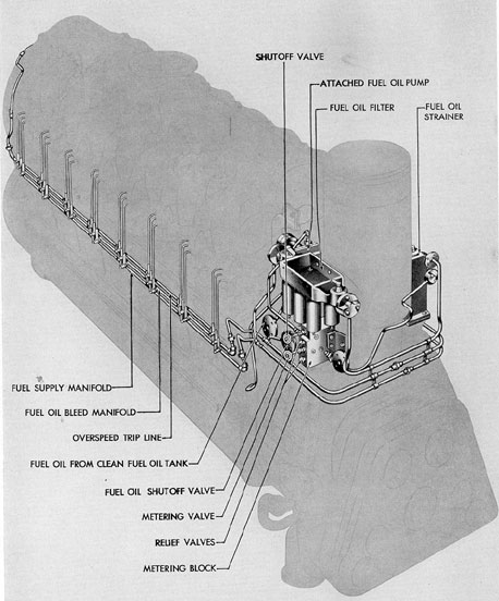
5E1. General. The attached fuel oil pump
draws fuel oil from the supply tank and forces
it through the fuel metering block, the strainer,
and the filter. From the filter, the fuel oil flows
to the fuel supply manifold, which is the bottom
tube of the multiple manifold assembly on each
cylinder bank, through a tube to a single jet
filter on each cylinder head. This filter is a
metal ribbon wound type with passages of approximately 0.001 inch in the element. From
the filter, the fuel flows through the jumper
tube that supplies the injector. The injector inlet
contains a filter to further prevent solid matter
from reaching the spray valve.
Two relief valves in the fuel metering block
limit the fuel oil pressure in the system. Any excess oil is bypassed back to the clean fuel oil
tank.
Surplus fuel from the injector flows
through a filter in the outlet passage so that any
reverse flow of fuel cannot carry dirt into the
injector. The surplus fuel passes from the injector through a jumper tube to the bleed manifold
which is the middle tube in the multiple manifold assembly on each cylinder bank. The fuel
from the bleed manifold on each bank flows
through a metering valve in the metering block,
then back to the clean fuel oil tank.
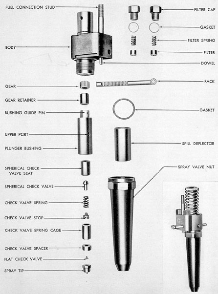
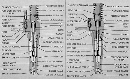
5E2. The unit injector. a. Description. On
the GM engine the fuel injection pump and
spray valve are combined into a single compact
unit called the unit injector, which meters the
fuel and also atomizes and sprays it into the
cylinder. The unit injector is held in position in
a water-cooled jacket in the center of the cylinder head. At the lower end, the injector forms a
gastight seal with the tapered seat in the cylinder head. All injectors in the engine are alike
and interchangeable. Fuel is supplied through
jumper tubes with spherical type gasketless connections.
The pumping function of the injector is
accomplished by the reciprocating motion of the
constant stroke injection plunger which is actuated by the injector cam on the engine camshaft
through the injector rocker lever. The position of the plunger, and thereby the timing, is adjusted by means of the ball stud and lock nut
at the injector end of the rocker lever. The
quantity of the fuel injected into each cylinder
(and therefore the power developed in that cylinder) is varied by rotating the plunger by
means of the injector control rack. A rack adjustment, called the micro-adjustment and located on the control linkage, permits balancing
the load of each cylinder while the engine is
running.
The unit injector is comprised of the various parts illustrated in Figure 5-11. Of these, the
principal parts are the body, spray valve nut,
bushing, plunger, needle valve or spherical type
check valve (depending on the type of injector), valve spring, and the spray tip.
The injector body is a heat-treated, alloy
steel forging with two flat surfaces extending
on opposite sides for holding the injector in a
vise when necessary. These surfaces are drilled
in line to support a part of the injector control
linkage. A small vent, just below the holding
down clamp seat, allows leakage fuel which
serves as the lubricant for the plunger and bushing to escape from the plunger spring chamber.
This hole also serves as a breather opening to
prevent pumping action by the plunger follower.
On some injectors, plunger pump fuel leakage
flows through a hollow drain dowel, then
through a drilled passage in the cylinder head
and back to the clean fuel oil tank.
The bushing is the cylinder for the plunger
pumping unit of the injector. It is located and
held against turning in the body by a guide pin
that fits into a groove at the upper end of the
bushing. Two openings in the bushing wall, on
opposite sides, serve as the inlet and bypass
ports for the fuel oil. The bottom surface of the
bushing is lapped to form an oiltight seal against
the full injection pressure.
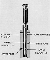
The unit injector pump plunger is made of
a special steel, lapped to a close fit in the bore
of the bushing. The clearance between the surface of the plunger and bushing is so fine that it
is usually measured by forcing a specific amount
of oil of a fixed viscosity between the surfaces
and measuring the time consumed.
The lower end of the plunger is cut away
to form a recess with an upper and a lower helical lip. These helical lips cover and uncover the
107
Figure 5-10. Isometric view of fuel injection system, GM.
108
Figure 5-11. Relative arrangement of parts, spherical check valve type unit injector, GM.
109
inlet and bypass ports in the bushing to control
the beginning and ending of the pumping part
of the plunger stroke. An oil hole, drilled horizontally from one side of the recess, through the
plunger to the other side, connects with a central
oil hole extending vertically from the bottom of
the plunger.
The plunger stroke remains constant at
about 3/4 of an inch. However, the pump
plunger does not pump fuel oil for the entire
length of the stroke. The effective pumping
stroke begins when the upper helical lip covers
the upper port and ends when the lower helical
lip uncovers the lower or bypass port. The upper
part of the plunger extends into the hub of the
control gear. When this gear is turned, through
the rack and linkage, the plunger rotates and
changes the angular position of the helical lips
with respect to the bushing ports, thereby changing the quantity of fuel injected and the timing
of the injection.
In the two types of unit injectors used, one
is equipped with a spherical check valve, the
other with a needle valve. In the spherical check
type valve, fuel, forced down by the pump
plunger, passes through a drilled passage in the
check valve seat and comes in contact with the
spherical check valve. Pressure of the fuel acts
on the differential area of the spherical check
valve, forcing it off its seat against the check
valve spring tension. The oil then goes past the
spring and around the check valve stop, through
the check valve spacer, around the flat check
valve, and out through the openings in the spray
tip.
In the needle valve type injector, fuel is
forced through drilled passages in the spacer,
down through a passage in the needle valve
spring cage and needle valve seat, and into an
annular groove at the bottom of this seat. It then
is forced up through a short inclined passage
leading to the needle valve against which the
fuel pressure acts. When the fuel pressure is
built up high enough to open the valve, the fuel
passes around the flat check valve and out
through the spray tip.
NOTE. On some injectors the spacer has
been eliminated and the fuel passes directly
from the pump plunger into the needle valve
spring cage.
Figure 5-12. Unit Injector plunger
and bushing, GM.
The needle valve or spherical check valve
spring, as well as the spray tip, are made of
hardened, chrome-vanadium steel. The spring
tension is such that it holds the valve on its
seat to insure quick opening and cutoff until the
fuel pressure is built up high enough to produce
a fine spray when the oil is forced through the
spray tip. The upper surface of the spray tip is
lapped to affect a seal against this pressure.
b. Operation. Fuel oil enters the unit injector body through a filter and passes around
the outside of the plunger bushing. From this
supply chamber around the outside of the
plunger bushing, the oil goes through the upper
and lower ports of the bushing and into the
pump chamber.
As the plunger is moved downward by the
rocker lever, fuel in the pump chamber is first
displaced through both ports into the supply
chamber around the bushing, until the lower
edge of the plunger closes the lower port. Fuel
110
Figure 5-13. Cross sections of needle valve and spherical check valve type unit injectors, GM.
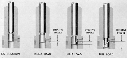
Figure 5-14. Plunger position at no Injection, idling, half load, and full load.
111
in the pump chamber is then displaced through
connecting central and transverse holes in the
lower port of the plunger and through the upper
port into the supply chamber. Further downward movement of the plunger causes the upper
lip to cover the upper port at which point the
effective pumping stroke begins and the fuel in
the pump chamber is then forced down through
the spray valve. Injection continues until the
lower lip on the plunger uncovers the lower port
in the bushing at which point the effective
pumping stroke ends. The fuel then bypasses
upward through the holes in the plunger and
through the lower port into the supply chamber.
This immediately lowers the pressure of the fuel
remaining in the pump chamber so that the
valve snaps shut to prevent dribble. On the return stroke, the upward movement of the
plunger uncovers the ports and allows fuel to
enter the chamber.
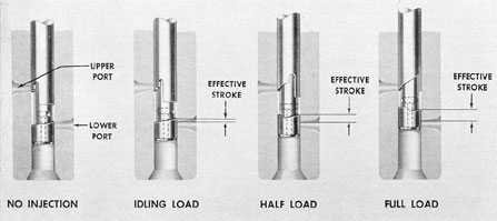
The cylinder load, that is, the amount of
fuel sprayed into the cylinder, is controlled by
the rotation of the pump plunger. Rotating the
plunger locates the helical plunger lips with respect to the port openings in the plunger bushing and thereby controls the amount of fuel injected into the cylinder. Figure 5-14 illustrates
the plunger position and effective stroke for no
injection, idling load, half load, and full load.
In addition to measuring the amount of
fuel, the injector pump plunger varies the timing
of injection. This is accomplished by means of
the upper helix on the pump plunger. The angularity of this helix causes injection to be advanced for a longer effective stroke of the
plunger (more fuel) and retarded for a shorter
effective stroke of the plunger (less fuel).
In the pressure chamber, fuel oil under
pressure works on the differential area of the
needle valve. The pump plunger creates a hydraulic pressure on the fuel oil in the pressure
chamber that is greater than the pressure of the
needle valve spring. This pressure working on
the differential area of the needle valve overcomes the spring tension and raises the needle
valve, opening the passage to the spray tip.
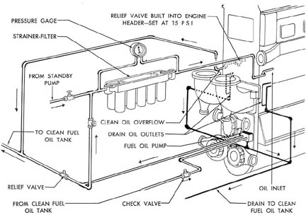
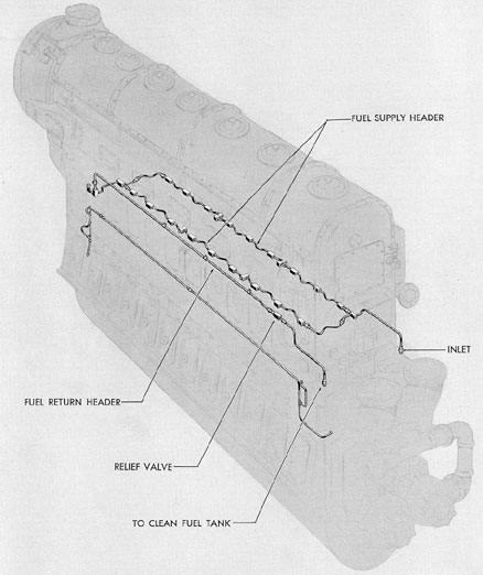
Figure 5-15. Fuel oil supply system, F-M.
112
Figure 5-16. Isometric view of fuel injection system, F-M.
113
Fuel oil enters the spray tip and the force
of the hydraulic pressure sprays the fuel oil
through the orifices of the spray tip at a 75-degree angle with the centerline of the cylinder.
Spray tips normally are marked to indicate
number and diameter of orifices and angle of
spray. For example: A spray tip marked 6-006-155 has 6 orifices, each measuring .006 inch,
directing the spray at a 155-degree included
angle.
F. FAIRBANKS-MORSE ENGINE FUEL OIL SYSTEM
5F1. General.The attached fuel oil pump
draws fuel by suction from the clean fuel oil
tank and delivers it through the strainer and
filter units to the engine main fuel oil header.
The pump has a greater capacity than is required to furnish fuel oil to the engine at maximum speed, therefore a pressure is built up in
the supply line to the engine. A relief valve in
the engine supply header prevents this pressure
from being built up above a certain desired
pressure, usually 15 psi. Pressure in excess of
this amount is relieved by the relief valve which
returns the excess oil to the clean fuel oil tank
by gravity.
Fuel oil delivered to the engine inlet is
piped along both sides of the engine through the
supply header which in turn is connected to the
fuel inlet ports of each injection pump.
Two injection pumps serve each cylinder,
one from the left side, the other from the right.
The pumps are actuated in proper sequence by
the cams on the camshafts. Each injection pump
delivers fuel oil to one of the injection nozzles,
which, like the pumps, are arranged two to a
cylinder, one on each side. The amount of fuel
the pumps deliver to the nozzles is regulated
by movement of the injection pump control
racks which are actuated, through plungers and
guides, by an injection pump control rod on
each side of the engine.
A drip pan under each injection pump collects any fuel oil that drains from the top of the
pump body. This oil is sent to the clean fuel oil
tank through tubes extending from the drip pan
at each end of the engine. Oil collecting on the
bottom of the injection nozzle compartments is
also drained into the clean fuel oil tank.
5F2. Fuel injection pump. a. Description.
The injection pumps receive fuel oil at low-pressure, measure it into correct amounts for
injection, build up a high pressure, and deliver
it to the injection nozzles at the proper time.
Each of the fuel injection pumps consists primarily of a tappet assembly, pump barrel,
plunger return spring, discharge valve with its
seat and spring, and the control rack.
A tappet assembly attached to the top of
the pump body, transforms the rotary motion of
the camshaft into up-and-down motion of the
pump plunger. The assembly is comprised of a
cam roller, a push rod, and a push rod spring. The
push rod spring holds the push rod and cam
roller against the camshaft cam. As the camshaft
rotates, the cam acts against the cam roller to
force the push rod down against the spring tension to actuate the injection pump plunger.
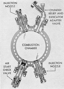
Figure 5-17. Arrangement of injection nozzles
in F-M cylinder.
114
Figure 5-18. Cross section of fuel injection pump, F-M.
The injector pump plunger moves vertically in the pump barrel, delivering fuel to the
injection nozzle by way of a discharge valve
and the injection tube connecting the pump and
the nozzle. At the base of the plunger is an
annular recess. The lip formed between the annular recess and the bottom of the plunger has
a slanting, or helical, edge. A vertical slot extends from the annular recess to the bottom of
the plunger. It should be noted that, except at
the slot, the edge of the helical lip at the bottom
of the plunger is constant or even. Hence it is
referred to as the constant beginning helical lip.
The edge of the helical lip toward the recess in
the plunger is helical, or slanting, and is referred to as the variable ending helical lip.
The plunger is lapped to an extremely close
fit in the bore of the pump barrel. These two
parts are always provided in pairs and should
not be separated.
The pump barrel is positioned in the pump
body by a setscrew which extends into an elongated slot at the lower part of the barrel. Fuel is
delivered to the pump chamber of the barrel
through a single inlet port which is also the bypass port.
The plunger spring returns the plunger to
the starting position when the high point on the
cam passes. The spring is held in position at the
upper part of the pump body by a snap ring.
The pump discharge valve is held in its
seat by a pump discharge valve spring. The
spring returns the valve to its seat at the end of
an effective pumping stroke.
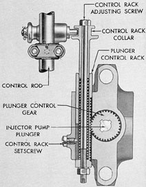
The amount of fuel delivered by the injection pump is controlled by rotating the pump
plunger. The mechanism by which this is accomplished is known as the fuel injection pump control rack and the control gear. The control gear
is splined to the pump plunger and meshes with
teeth in the control rack. Any lateral movement
of the rack is transmitted to the control gear,
causing the pump plunger to rotate. The control
racks have calibration scales for reference in
checking operating conditions under various engine loads. Normally the control racks are set
at the 0 marking, as indicated by a pointer,
when in the no fuel position. Each of the control
racks is adjustable to the correct calibration by
means of the control rack adjusting screw.
The control racks are connected to the control rod at the control rack collar. The control
115
Figure 5-19. Cutaway of fuel injection pump, F-M.
Figure 5-20. Fuel injection pump parts, F-M.
116
Figure 5-21. Details of injection pump plunger
and barrel, F-M.
Figure 5-22. Cross section through control
rack, F-M.
Figure 5-23. Position of GM fuel injection pump plunger at no injection, idling half load, and full load.
117
rod is connected to the engine governor by a
linkage. Thus the rotary position of the pump
plungers, and hence, the amount of fuel delivered, can be directly controlled by the governor.
It should be noted that there is no means
provided for advancing or retarding the time of
injection in the cylinder for a change in fuel
supply as there is in the unit injector pump of
the GM engine.
b. Operation. Figure 5-23 shows how the
amount of fuel delivered through the discharge
valve is varied by rotating the pump plunger.
The plunger stroke remains constant at about
5/8 of an inch The effective pumping stroke begins
when the constant beginning edge of the
helical lip covers the fuel port. The pumping
stroke ends when the variable ending edge of
the helical lip uncovers the port, allowing the
fuel oil remaining in the chamber to flow
through the bypass area in the pump plunger.
The first picture in Figure 5-23 shows the
pump plunger in a position in which the vertical
slot is aligned with the fuel port. This is the no
fuel position. Any downward movement of the
pump plunger in this position allows the fuel to
pass from the chamber beneath the pump
plunger, through the slot and out through the
inlet port. Thus no fuel is delivered through the
discharge valve.
When the pump plunger is rotated slightly,
a relatively shallow depth of the helical lip is
aligned with the fuel inlet port. The effective
pumping stroke is short, and only a small
amount of fuel is delivered through the discharge valve such as is required for an idling
engine.
The third and fourth pictures in Figure
5-23 shows the rotary position of the pump
plunger at half load and full load fuel delivery.
Fuel oil is supplied to the fuel injection
pump through a line from the engine main fuel
oil header. The fuel oil enters the fuel port in
the pump bushing at approximately 15 pounds'
pressure and fills the chamber below the pump
plunger. At the proper time the pump plunger is
actuated by the cam on the engine camshaft
through the tappet mechanism on the pump.
The force exerted on the fuel oil in the chamber
beneath the pump plunger overcomes the spring
tension on the discharge valve and opens the
valve. The oil then passes through holes below
the discharge valve seat, through the discharge
valve cage, and into the high-pressure line to the
injection nozzle.
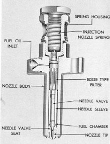
Fuel enters the annular groove in the injection nozzle and is directed down through
longitudinal grooves comprising the edge type
filter. The clearance between the grooves of the
filter and the injector nozzle body is approximately 0.0015 inch. The fuel oil is forced from
the filter, down through flutes on the outside of
the needle sleeve, then through needle sleeve
holes at the bottom of the flutes to enter a fuel
chamber in the needle sleeve. In this chamber,
the hydraulic pressure of the fuel, acting on the
differential area of the valve, lifts the valve from
the needle valve seat. The oil is then discharged
into the combustion chamber through the nozzle
tip. As soon as the pressure from the fuel injection pump diminishes, the spring in the nozzle
forces the needle valve closed.
The three orifices in the nozzle tip are
0.0225 of an inch in diameter and are positioned
to direct the spray at a 15-degree angle for thorough distribution in the combustion chamber.