3A1. Introduction.All of the present fleet
type submarines are equipped with engines
manufactured either by the Cleveland Diesel
Engine Division, General Motors Corporation,
Cleveland, Ohio, or by Fairbanks, Morse and
Company, Beloit, Wisconsin. These engines
have been in the process of development for
the past several years, and the latest models
proved highly dependable under wartime operating conditions.
Before World War II, these engines were
used almost exclusively on submarines. With
the expansion of the Navy, however, these engines have also been used on destroyer escorts,
amphibious craft, escort type patrol vessels, and
various auxiliary craft.
The following sections are devoted to the
discussion of basic diesel engine construction
and the application of these basic principles to
the General Motors and Fairbanks-Morse engines.
3A2. General Motors engines.Two models
of GM main engines are found in fleet type
submarines today, Model 16-248 and Model
16-278A. The former was installed exclusively
in General Motors engine equipped vessels until early in 1943 when Model 16-278A was
introduced. All General Motors installations
since that time have been Model 16-278A engines (Figures 1-10 and 1-11). Basically the
two models are similar. The principal differences are in the size and design of the parts,
methods of construction, and type of metals
used. In the following chapters all references
are based on the current Model 16-278A. Important differences between the two models,
however, will be noted.
The GM engine is a 16-cylinder V-type
engine with 2 banks of 8 cylinders each The
engine operates on the 2-stroke cycle principle,
is air started, and is rated at 1600 bhp at 750
rpm. The size of the bore and stroke of the 16-248 engine is 8 1/2 inches and 10 1/2 inches respectively as compared to 8 3/4 inches and 10 1/2
inches for Model 16-278A.
The General Motors Corporation also
supplies a Model 8-268 auxiliary engine for fleet
type submarines. This is an 8-cylinder, in-line,
2-cycle, air starting engine, rated at 300 kw
generator output at 1200 rpm. The size of the
bore and stroke is 6 3/8 inches and 7 inches respectively.
The tables at the end of this chapter, pages
78 and 79, contain engine data, ratings, and
clearances for General Motors main engines
and auxiliaries.
3A3. Fairbanks-Morse engines.There are
two types of F-M main engines in use in modern submarines (Figures 1-12 and 1-13). The
model number for each is 38D 8 1/8. The basic
difference between them is the number of cylinders, one being a 9-cylinder and the other a
10-cylinder engine. Both engines have the same
bore and stroke and in most respects are similar in principle, design, and operation.
The F-M 38D 8 1/8 model is an opposed
piston, in-line, 2-cycle, 9- or 10-cylinder engine
employing air starting and rated at 1600 bhp
at 720 rpm. Bore and stroke are 8 1/8 and 10
inches respectively.
An auxiliary engine, Model 38E 5 1/4, is
also supplied by Fairbanks, Morse and Company. This is a 7-cylinder, opposed piston, 2
cycle, air starting engine rated at 300 kw generator output at 1200 rpm. The bore is 5 1/4
inches and the stroke 7 1/4 inches.
The tables at the end of this chapter, page
80, contain engine data, ratings and clearances
for Fairbanks-Morse main engines and auxiliaries.
3A4. Classification of engine components.
To simplify the study of the design, construction, and operation of the component parts of
the diesel engines in the following sections of
this chapter, the parts have been classified under three subjects as follows: 1) main stationary parts, 2) main moving parts, and 3) valves
and valve actuating gear.
Section 3B deals with engine components
as listed above, in general. Sections 3C and 3D
deal with the same components as applied to
the GM and F-M engines respectively. In all
34
instances the ends of the engines will be referred to as the blower and the control ends.
It should be noted that the blower end of the
F-M engines is also the generator coupling end,
whereas the blower end of the GM engines is
opposite the generator coupling end.
B. GENERAL DESCRIPTION OF ENGINE COMPONENTS
3B1. Main stationary parts.a. Frame.
The framework of the diesel engine is the load
carrying part of the machinery. The design of
diesel engine frames has undergone numerous
changes in recent years. Some of the earlier
types of framework which were eventually
abandoned were: 1) A-frame type, 2) crankcase type, 3) trestle type, 4) stay-bolt or tie
rod type.
The framework used in most modern engines is usually a combination of these types
and is commonly designated as a welded steel
frame. A frame of this type possesses the advantages of combining greatest possible strength,
lightest possible weight, and greatest stress
resisting qualities.
The welded steel type of construction is
made possible by the use of recent developments in superior quality steel. For diesel engine frame construction, steel is generally used
in thick rolled plates which have good welding
quality. In this type of construction, deckplates
are generally fashioned to house and hold the
cylinders, and the uprights and other members
are welded, with the deckplates, into one rigid
unit.
b. Oil drain pan. The oil drain pan is attached to the bottom of the cylinder block and
serves to collect and drain oil from the lubricated moving parts of the engine. The bottom
of the oil pan is provided with a drain hole at
each end through which oil runs to the sump
tank. In some installations the bottom of the
pan slopes toward one end or the other of the
engine.
Oil drain pans require little maintenance.
They should be cleaned and flushed of any
residual dirt during major overhaul periods.
New gaskets should be installed at these times
to assure an oiltight seal.
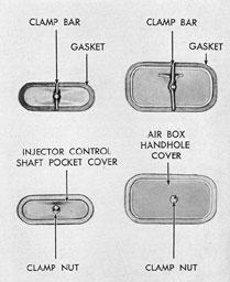
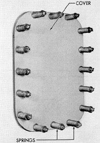
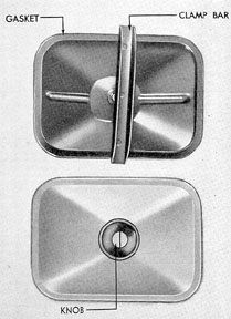
c. Access doors and inspection covers.
The cylinder block walls are equipped with
access doors or handhole covers. With the doors
or covers removed, the openings furnish access
to cylinder liners, main and connecting rod
bearings, injector control shafts, and various
other parts for inspection and repair. The doors
are usually secured with handwheel or nut
operated clamps and are fitted with gaskets to
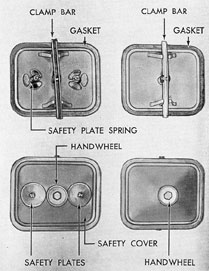
keep dirt and foreign material out of the interior. Some of these access doors or inspection
covers may be constructed to serve as safety
covers. A safety cover is equipped with a
spring-loaded pressure plate. The spring maintains a pressure which keeps the cover sealed
under normal operating conditions. An explosion or extreme pressure within the crankcase
overcomes the spring tension and the safety
cover acts as an escape vent, thus reducing
crankcase pressure.
d. Cylinder and cylinder liners. The
cylinder is the enclosed space in which the
mixture of air and fuel is burned. A cylinder
may be constructed of a varying number of
parts among which the essentials are the cylinder jacket, the cylinder liner, and in most cases
the cylinder head. In most designs the space
between the cylinder jacket and the liner is
cored to carry circulating water for cooling
purposes.
There are two general types of cylinder
liners. One, the wet type, is a replaceable liner
that makes direct contact with the cooling
water; the other, the dry type, is a replaceable
liner that fits into a water-cooled jacket without
making direct contact with cooling water. All
submarine diesel engines under consideration
here use the wet type cylinder liners.
e. Cylinder head. The cylinder head
seals the end of the cylinder and usually carries
the valves. Heads must be strong enough to
withstand the maximum pressures developed in
the cylinders. Also, the joint between the cylinder and the head must be gastight. Due to the
high temperatures encountered, cylinder heads
must be water cooled. To accomplish this,
water passages are cored in the head during
the casting process. Valves usually found in the
head are the exhaust valves, injection valves,
and air starting valves.
3B2. Main moving parts.a. General. The
main moving parts of a diesel engine are those
35
that convert the power developed in the cylinders by combustion to mechanical energy, that
is delivered to the shaft. These parts are used
to change the reciprocating motion of the pistons in the cylinders to rotary motion at the
engine final drive, and may be divided into
three major groups:
1. Those parts having rotary motion, such
as crankshafts and camshafts.
2. Those parts having reciprocating motion,
as, for example, the pistons and piston rings.
3. Those parts having both reciprocating
and rotary motion, such as the connecting rods.
b. Crankshaft. The crankshaft transforms the reciprocating motion of the pistons
into rotary motion of the output shaft. It is one
of the largest and most important moving parts
of a diesel engine.
The materials used in the construction of
crankshafts vary greatly, depending on the size
of the shaft, speed of the engine, horsepower of
engine, and number of main bearings. Regardless of materials used, crankshafts are always
heat treated. This is necessary in order to give
uniform grain structure, which increases ductility and capacity for resisting shock. The tensile
strength of crankshaft materials varies from
60,000 psi to as much as 100,000 psi. Crankshafts may be either forged or cast. They may
be either made up in one section, or in two or
more with the sections interchangeable for
economy in construction and replacement.
Crankshafts are machined to very close limits
with a high finish and are balanced both statically and dynamically.
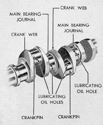
The crankshaft consists essentially of a
number of cranks placed at equal angular intervals around the axis of the shaft. Between
the cranks are the crankshaft supports commonly referred to as the journals. Each crank
on a crankshaft is made up of the crankpin,
which is the journal for the connecting rod
bearing, and two crank webs (Figure 3-1).
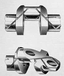
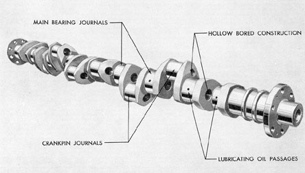
Journals, crankpins, and webs are drilled
for the passage of lubricating oil (Figure 3-2).
All such holes are usually straight to facilitate
construction and cleaning of the passages. In
larger engines, crankshafts are practically always constructed with hollow main bearing
journals and crankpins. This construction is
Figure 3-1. Nomenclature of crankshaft parts.
Figure 3-2. Sections of crankshaft showing oil
passages and hollow construction.
36
much lighter than a solid shaft and is better
adapted for carrying the lubricating oil to
various bearings in the engine. In large engines,
the crankshaft is sometimes built up by pressing
the journals into the webs. In this type, generally, the crankpin and its two adjacent webs
are forged or cast in one piece, this unit then
being joined to other cranks by hydraulically
pressing them onto the main bearing journals.
The cranks are held at the proper angles during
this process, after which the assembled shaft is
put in a lathe and finished to size.
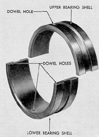
c. Main bearings. The function of the
main bearings is to provide supports in which
the crankshaft main bearing journals may revolve. In the diesel engines under discussion,
modern bimetal or trimetal, split sleeve, precision type main bearings are used exclusively.
Bimetal bearings consist of a thin inner layer of
soft low-friction metal encased in a shell of
harder metal fitted to the bearing support or
bearing cap. Trimetal bearings have an intermediate layer of bronze between the shell and
soft metal layers. Both types are split sleeve,
divided horizontally through the center, for
installation. Precision type manufacture requires that the bearing housing be precision
bored to a close tolerance and that the bearing
halves, when tightly drawn together, align perfectly and fit the bearing journals with a predetermined clearance. The purpose of this
clearance is to provide for a thin film of lubricating oil which is forced under pressure between the journals and bearing surfaces. Under
proper operating conditions this oil film entirely
surrounds the journals at all engine load
pressures.
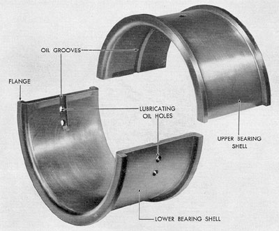
All main bearings contain oil inlet holes
and oil grooves which permit the oil to enter
and be evenly distributed throughout the inside
of the bearing. These oil inlets and grooves are
invariably in the low oil pressure area of the
bearing.
Proper bearing lubrication depends upon
accurate bearing clearances as well as the type
of lubrication. Too little clearance will cause the
bearing to run hot and wipe out under continued operation. At high operating speeds with
too little clearance, the load pressure on the
bearing does not leave sufficient room for the
lubricant to prevent a metal-to-metal contact
between the journal and bearing surfaces. Excessive clearance permits the free flow of the
fluid oil to the edges of the bearing. This reduces the pressure developed and consequently
may overload the bearing. The stress of overload will cause the bearing to wipe and eventually burn out. Both bearing clearances and the
amount of wear may be checked by measuring
the thickness of the soft metal lining of the
bearing shell either with a ball point micrometer or by the use of appropriate feeler gages.
Proper seating of the bearing shells and
proper clearances of precision type bearing
shells require that the bearing caps be drawn
to the proper tightness. This is done with
a torque wrench by means of which the proper
torque limits in foot-pounds are obtained. As
this torque varies with engine models, the current instructions should be consulted.
d. Pistons. The function of a piston is
to form a freely movable, gastight closure in
Figure 3-3. Main bearing shells.
37
the cylinder for the combustion chamber. When
combustion occurs, the piston transmits the
reciprocal motion or power created to the connecting rod. Pistons for all the modern submarine 2-stroke cycle diesel engines are of the
trunk type. Pistons of the trunk type have
sufficient length to give adequate bearing surface against the side thrust of the connecting
rod. Trunk type pistons have a slight amount
of taper at the crown end of the piston to
provide for the greater expansion of the metal
at the combustion end where temperatures as
high as 3000 degrees F may be encountered. This taper
is sufficient so that at normal operating temperatures the piston assumes the same diameter
throughout its entire length.
The piston crowns on both the GM and
F-M engines are concave. The purpose of this
shape is to assist in air turbulence which mixes
fuel with air during the last phase of the compression stroke.
Pistons are usually constructed of either a
cast iron or aluminum alloy. They must be
designed to withstand the gas pressure developed in the combustion chamber during the
compression and expansion strokes. They must
also be light enough to keep the inertia loads on
the piston pins and main cranks to a minimum.
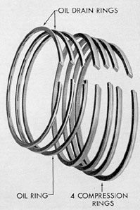
e. Piston rings. Piston rings have the
following three primary functions:
1. To seal compression in the combustion
chamber.
2. To transfer heat from the piston to the
cylinder wall.
3. To distribute and control lubricating
oil on the cylinder wall.
In general, piston rings are of two types.
One, the compression type ring, serves primarily
to seal the cylinder against compression loss;
the other, the oil type ring, distributes oil on the
cylinder walls and controls cylinder wall lubrication by collecting and draining excess oil.
Piston rings are generally constructed of
cast iron. On the average diesel piston there are
four to five compression rings and two or three
oil control rings.
f. Piston pins. Each piston is connected
to the connecting rod by a piston pin or wrist
pin. This connection is through bored holes in
the piston pin hubs at the center of the piston
and the integral hub of the connecting rod. The
piston pin must be strong enough to transmit
power developed by the piston to the crankshaft through the connecting rod. Piston pins
are usually hollow and are made of special alloy
steels, case hardened and ground to size. The
connection between the piston and the piston
pin is either by means of needle type roller bearings or by plain bushings. The ends of the pins
must not protrude beyond the surface of the piston, and their edges must be rounded to facilitate
entry of the piston into the cylinder. This is
usually accomplished by means of piston pin
caps.
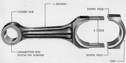
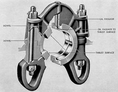
g. Connecting rods. Just as its name implies, the connecting rod connects the piston with
the crankshaft. It performs the work of converting the reciprocating, or back-and-forth, motion
of the piston into the rotary, or circular, motion
of the crankshaft. The usual type of connecting
rod is an I-beam alloy steel forging, one end of
which has a closed hub and the other end an
integral bolted cap. The cap is accurately located by means of dowel pins. Through the
closed hub, the connection is made between
the piston and the connecting rod by means of
the piston pin. At the other end, the connecting
rod bearing connection is made between the connecting rod and the crankshaft. The shaft of
the connecting rod is drilled from the connecting
rod bearing seat to the piston pin bushing seat.
Through this passage, lubricating oil is forced
from the connecting rod bearing to the piston
pin bearing for lubrication and piston cooling.
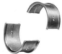
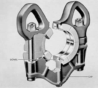
h. Connecting rod bearings. The purpose of these bearings is to form a low-friction,
well-lubricated surface between the connecting
rod and the crankshaft in which the crankpin
journals can revolve freely. The bearings used
are generally of the same material and type as
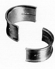
the main bearings. Connecting rod bearings consist of two halves or bearing shells. The backs
of these shells are bronze or steel, accurately
machined to fit into a precision machined bearing seat in the connecting rod. The shells are
lined with a layer of soft metal of uniform thickness. When the bearing caps are drawn tight on
the connecting rod, the contact faces of the
bearing shells form an oiltight joint. Also, because of the precision manufacture of all parts,
38
the bearing shells give the proper clearance
between the bearing shells and the crankpin
journals. The connecting rod bearings are pressure lubricated by oil forced through oil passages
from the main bearings to the crankpin journals.
The oil is evenly distributed over the bearing
surfaces by oil grooves in the shells.
Figure 3-4. Connecting rod bearing shells.
3B3. Valves and valve actuating gear.a.
General. Control of the flow of fuel, inlet air,
starting air, and exhaust gases in a diesel cylinder is accomplished by means of various types
of valves. The timing and operation of these
valves, for the various processes in relation to
piston travel and correct firing sequence, are the
main functions of the valve actuating gear.
Since certain phases of timing, such as the
geometrical angle of the crankshaft cranks and
the geometrical angle of the camshaft cams, are
fixed, timing adjustments are made through the
valve actuating gear. Hence, timing adjustments
must be made with extreme accuracy and the
valve actuating gear must function perfectly for
efficient engine operation.
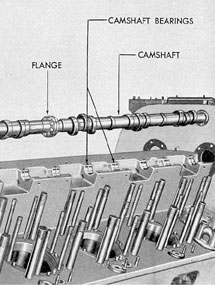
b. Camshafts. The purpose of the camshafts in submarine diesel engines is to actuate
exhaust valves, fuel injectors, fuel injection
pumps, and air starting valves according to the
proper timing sequence of that particular engine.
In order to perform these functions at the
various cylinders in relation to their proper firing
order, the camshafts are timed or synchronized
with the operation of the crankshaft through the
camshaft drive. In addition to actuating valves,
camshafts, on some engines, are also used for
driving auxiliaries such as governors and
tachometers.
Camshafts are usually constructed in one
or two parts. The number of cams on a camshaft is determined by the type and cycle of
engine. The cams and camshafts are usually
forged integral and ground to a master camshaft.
c. Valves. The important valves found
on typical diesel cylinders and their functions
are:
1. Exhaust valves. Exhaust valves are used
to allow the exhaust gases of combustion to
escape from the cylinders. They are subject to
extremely high temperatures and are therefore
made of special heat-resistant alloys. In some
large engines, the exhaust valves are water
cooled.
2. Inlet valves. Inlet valves are used to
govern the entrance of air in the cylinder of a
4-stroke cycle engine. Inlet valves are not used
Figure 3-5. Valve actuating gear assembly.
39
in modern submarine diesel engines, having been
replaced by inlet ports.
3. Fuel injection valves. Fuel injection
valves are used to inject the fuel spray into the
cylinder at the proper time with the correct
degree of atomization. In addition, some injection valves also measure the amount of fuel
injected.
4. Air starting valves. Air starting valves
are used to control the flow of starting air during
air starting of an engine. These valves are normally of two types, air starting check valves and
air starting distributor valves.
5. Cylinder test valves. Each cylinder is
provided with a test valve which is used to vent
the cylinder before starting. This valve is also
used to relieve the cylinder of compression when
turning over the engine by hand. The same valve
is used far taking compression and firing
pressure readings of the cylinder while the engine
is in operation.
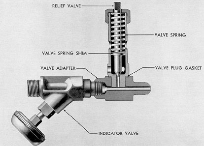
6. Cylinder relief valves. A cylinder relief,
or safety, valve is located on each cylinder of all
submarine type engines. The function of this
valve is to open and relieve the cylinder when
pressure inside the cylinder becomes excessive.
These valves are adjustable to be set at varying
pressures according to the particular installation.
When pressure drops below the setting at which
the valve opens, the valve closes automatically.
d. Valve actuating gear. Motion of the
cams on the camshaft is transmitted to valves,
injectors, and injector pumps by means of rocker
arms or tappet assemblies. The rocker arms and
tappets normally are spring loaded and make
contact with the cams by means of cam rollers.
Adjustments of the various springs and rods are
very important, as they are normally the means
by which the engine is correctly timed.
C. GENERAL MOTORS ENGINE COMPONENTS
3C1. General.Descriptions of engine components in this section apply only to the General
Motors engine.
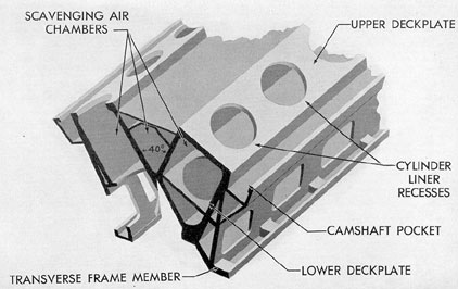
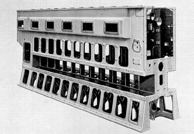
3C2. Main stationary parts.a. Cylinder
block. The cylinder block of the GM engine
(Figure 3-8) is fabricated from forgings and
steel plates welded together to form a single
unit. The assembly is designed with two cylinder
banks, the axes of which are 40 degrees apart,
forming the V-type design of the engine. The
unit is fabricated from main structural pieces
called transverse frame members, upper and
lower deckplates for each bank, and cross braces
all welded into one rigid compact unit. The
upper and lower deckplates are bored to accommodate the cylinder liners. The space between these deckplates, as well as the space
between the two banks of cylinders, serves as a
scavenging air chamber.
The forged transverse members in the bottom of the cylinder block form the mounting
pads for the lower main bearing seats. The camshaft bearing lower seats are an integral part
of the cylinder block. These bearing seats and
their caps are match-marked and must be kept
together.
Removable handhole covers close the
openings in the sides of the cylinder block. Access to
the injector control shaft is obtained by removing the top row of small handhole covers. The
middle row of handhole covers permits access
to the scavenging air box for inspection of the
cylinder liners and piston rings. The bottom row
of handhole covers permits access to the crankshaft, connecting rod, and bearings.
b. Engine oil pan. The engine oil pan is
bolted to the bottom of the cylinder block. The
bottom of the oil pan is provided with a drain
hole at each end. One end of the oil pan is
fastened to the camshaft gear train housing and
the other end is fastened to the blower bottom
housing. The lubricating oil from these units
drains into the oil pan. The pan is constructed
of welded steel in the 16-278A and of an aluminum alloy casting in the 16-248.
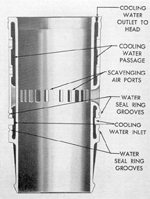
c. Cylinder liner. The cylinder liner
(Figure 3-11) is made of cast iron with a cored
or hollow space in the wall through which cooling water is circulated. Water enters through a
synthetic rubber gasket sealed connection near
the bottom of the cylinder and circulates out
through similarly sealed steel ferrules into the
cylinder head. The cylinder liner is held in the
engine block by the lower deckplate and a
Figure 3-10. Injector control shaft and air box
handhole covers, GM.
42
recess in the upper deckplate, and is held securely
to the cylinder head by six steel studs and nuts
The joint between the liner and the lower deck
plate is made up with an oil-resistant seal ring
made of neoprene which is compressed in a
groove in the deckplate bore. This makes a tight
joint and prevents the leakage of scavenging
air from the air chamber and the leakage of oil
from the crankcase into the air chamber. A solid
copper gasket, slightly recessed in a groove of
the cylinder liner, seats against the cylinder
head to form a pressure seal. Scavenging air
intake ports are located near the center of the
liner. They also serve as piston and ring inspection ports.
The distance from the upper ends of the
scavenging air ports to the finished top of the
cylinder liner must be closely held to the required dimension, so that the opening and closing of these ports by the travel of the piston are
accurately timed in relation to the respective
opening and closing of the exhaust valves.
In recent years it has been found that the
wearing qualities of the liner can be greatly increased by chrome plating the inside of the
liner. These chrome-plated liners are used in all
late installations.
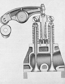
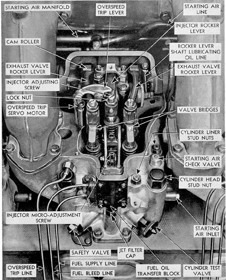
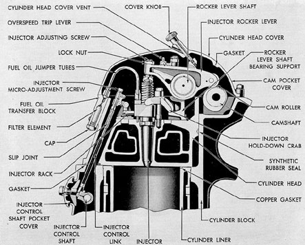
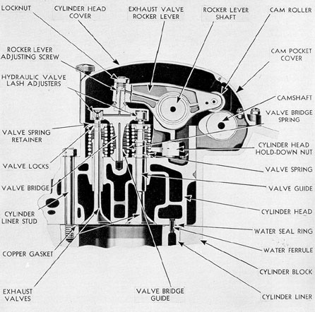
d. Cylinder head. The cylinder head attaches to the cylinder liner to form the top
closure of the combustion chamber. It forms the
support and houses the four exhaust valves, the
unit injector, and the rocker lever assemblies. It
also contains the overspeed injector lock, air
starter check valve, cylinder relief valve, and
cylinder test valve (Figure 3-12).
The cylinder head is an individual unit
for each cylinder. It consists of an alloy iron
casting, cored with water cooling passages. Cooling water flows from the cylinder liner through
synthetic rubber sealed steel ferrules, and circulates through the cylinder head. It then passes
through a watertight connection into the water
jacket of the exhaust elbow. All cylinder heads
are equipped with a pressed steel or aluminum
alloy cover secured by a handwheel nut. This
cover has breather openings which serve as
ventilating ports for the crankcase breather
system. Each cylinder head is fastened to the
cylinder block by four hold-down studs and
nuts. The joint between the cylinder liner and
Figure 3-11. Cross section of cylinder liner, GM.
cylinder head is sealed against compression loss
by a solid copper gasket which is slightly recessed in a groove of the cylinder liner. All
other joints or openings of the cylinder head are
made watertight or oiltight by gaskets.
3C3. Main moving parts.a. Crankshaft.
The GM crankshaft (Figure 3-15) is an integral
type, alloy steel forging, heat treated for stress
and wear resistance, and dynamically and statically balanced. Shaft and crankpins are hollow
bored to reduce weight and bearing load.
The entire crankshaft is machine finished, and
the main bearing and crankpin journals are precision ground. Crankshafts for right-hand and
left-hand engines are interchangeable. There are
eight cranks spaced 45 degrees apart and nine
main bearing journals on each crankshaft. In
both right-hand and left-hand engines, the cylinders are numbered from 1 to 8 inclusive in the
right bank, and from 9 to 16 inclusive in the
left bank. Cylinders 1 and 9 are at the blower
end of each engine. Two pistons that are
43
Figure 3-12. Cylinder head, GM.
44
opposite each other in the two banks are connected
to each crank by connecting rods. Each crank or
crankpin is referred to by the numbers of the
two cylinders to which it is related.
The firing interval is alternately 5 degrees
and 40 degrees and these intervals are determined by the angle between the cylinder banks,
which is 40 degrees, and by the relation of the
crankpin positions of successively fired cylinders,
which is 45 degrees. Two successively fired cylinders are connected either to two separate
crankpins that are 45 degrees apart, or to one
crankpin. When two successively fired cylinders
have crankpins that are 45 degrees apart, which
is 5 degrees greater than the bank angle of 40
degrees, the firing interval is 5 degrees. When
two successively fired cylinders are connected to
one crankpin, the firing interval is the same as
the bank angle, which is 40 degrees.
Oil passages are drilled through each crankpin, crank webs, and main bearing journals, for
lubricating oil to flow under pressure from the
main bearings to the connecting rod bearings.
The connection between the crankshaft
and the main generator is by means of an elastic
coupling.
b. Main bearings. The crankcase contains nine bearings (Figures 3-16 and 3-17) for
the support of the crankshaft. Each main bearing consists of an upper and lower double
flanged precision bearing shell. Two types of
main bearing shells are used. One type is bronze
backed with a centrifugally cast lining of high
lead bearing metal known as Satco metal. The
other type is steel backed with an intermediate
lining of bronze and lined with Satco metal.
The bearings are carried in a steel bearing
support and held by a steel bearing cap. Both
bearing supports and bearing caps are made of
drop-forged, heat-treated steel. Each of the bearing supports is secured to the main frame of the
crankcase. Two large dowel pins locate the supports for perfect alignment.
The upper bearing shell is mounted in the
bearing cap, the lower shell in the main bearing
seat. The joint faces of the upper and lower
bearing shells project slightly from the seat and
cap. This is to insure that the backs of the shells
will be forced into full contact when the cap is
fully tightened. A drilled hole in the upper shell
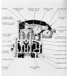
Figure 3-13. Cylinder head cross section through
exhaust valves, GM.
Figure 3-14. Cylinder head cross section through
injector, GM.
45
Figure 3-15. Crankshaft for GM engine.
fits on a dowel pin in the cap. The dowel pin
locates the upper shell in the bearing cap and
prevents both the upper and lower shells from
rotating.
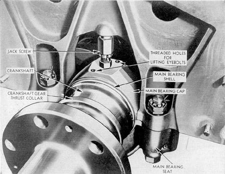
Bearing caps are held down on the bearings
by jack screws locked with cotter pins. The
jack screw fits into a recess in the arch of the
crankcase frame and takes the upward thrust
on the bearing cap. Close fit between shoulders
on the crankcase frame prevents side play in
the bearing cap. End play is controlled by two
dowel pins. When the bearing supports and caps
are assembled on the crankcase frames, the seats
for the bearing shells are accurately bored in
dine, and the ends of its faces are finished for a
close fit between the bearing shell flanges.
Each bearing shell is marked on the edge
of one flange. For example, the designation 2-L-B.E. indicates that the shell is for the No. 2 main
bearing, that it is the lower shell, and that the
flange of the shell thus marked should be placed
toward the blower end of the engine. The main
bearing nearest the blower end of the engine is
the No. 1 main bearing. The rear main bearing
(No. 9) is the thrust bearing. Thrust bearing
shells are the same as the other main bearing
shells except that the bearing metal is extended
to cover the flanges. With the exception of the
thrust bearing, all upper bearing shells are alike
and interchangeable before they are assembled
and marked This is also true of the lower bearing shells. Upper and lower shells, however, are
not interchangeable with each other.
Each lower bearing shell has an oil groove
starting at the joint face and extending only
partially toward the center of the bearing surface. The upper bearing shells are similarly
grooved except that the groove is complete from
joint face to joint face.
The main bearings are lubricated by oil
under pressure received from the oil manifold
under the bearing supports. The oil is forced up
through a passage in the bearing support and
through holes drilled in the lower bearing shell.
From these holes, oil flows the entire length of
the oil groove formed by the combined upper
and lower shells. The oil lubricates the entire
bearing surface and is carried off through the
46
drilled passages in the crankshaft to the connecting rod bearings.
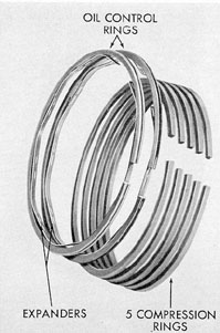
c. Pistons and piston rings. The pistons
for GM engines are made of cast iron alloy
which is tin plated. Each piston is fitted with five
compression rings at the upper, or crown, end
and two oil control rings at the bottom, or skirt,
end. In latest installations, the oil control rings
are of the split type backed by expanders. All
piston rings are made of cast iron.
The bored holes in the piston pin hubs are
fitted with hard bronze bushings which are cold
shrunk in the piston bores. The outer ends of the
bore for the piston pin are sealed with cast iron
caps to prevent injury to the walls of the cylinder from floating piston pins.
The bores in the piston pin bushing are
accurately ground in line for the close, but floating, piston pin fit. Each bushing has a number
of small oil grooves cut lengthwise in the bore
and these receive lubricating oil that splashes
from the sprayed head and side wall surfaces.
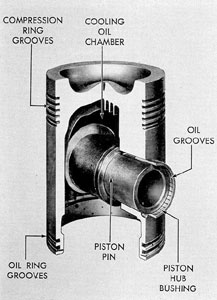
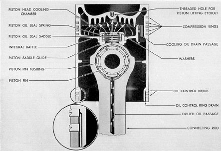
A cooling oil chamber is formed by an
integral baffle under the piston crown. Lubricating oil under pressure flows from the top of the
connecting rod, through a sealing member, and
into the cooling chamber. The oil seal is a spring
loaded shoe which rides on the cylindrical top
of the connecting rod. The heated oil overflows
through two drain passages.
d. Piston pins. The piston pin used on
the GM engine is full floating, hollow bored,
and case hardened on the bearing surface. The
connection between connecting rod and the
piston is by means of the connecting rod piston
pin bushing. This bushing rotates freely inside
the integral end of the connecting rod, and the
connection is completed by pushing the piston
Figure 3-16. Main bearing cap installed, GM.
47
Figure 3-17. Main bearing shells. GM.
pin through the connecting rod piston pin bushing and the piston pin hub bushings.
In some older installations a needle type
bearing containing three rows of 53 small roller
bearings each was used instead of the connecting rod piston pin bushing. These have now
been replaced by the bushing type of bearing.
The connecting rod piston pin bushing is
constructed of steel-backed bronze. The entire
length of the inner surface of the bushing is
grooved to provide for lubrication of the piston
pin assembly.
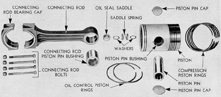
e. Connecting rods and connecting rod
bearings. GM connecting rods are made of
alloy steel forgings. The rod is forged in an
I-section with a closed hub at the piston pin end
and with an integral cap at the lower end. The
cap is saw-cut from the rod in the machining
operation. The cap is accurately located on the
rod by two dowel pins. On the 16-248 the cap
is fastened to the rod by four studs and castle
nuts. For greater security, the studs are pinned
in the rod. On the 16-278A the cap is fastened
to the rod by four bolts with castle nuts. The
crankpin bearing hub of the rod is turned to a
lateral diameter which is smaller than the cylinder bore, so that the connecting rod will pass
through the cylinder bore.
The connecting rod bearing is made up of
upper and lower bearing shells. There are two
types of connecting rod bearing shells used in
the Series 16-278A engines. One type is bronze
backed with a centrifugally cast lining of Satco
metal of the same composition as that used in
the main bearings. The other type is steel backed
with an intermediate lining of bronze and an
inner lining of the same bearing material. Connecting rod bearing shells are marked similarly
48
Figure 3-18. Cutaway of piston, GM.
to main bearing shells to indicate their position
in the engine.
In both types of bearings the lower bearing
shell is located in the connecting rod bearing
cap by means of a dowel pin. This pin prevents
the lower shell from rotating. The joint faces
between the upper and lower shells are compressed when the cap is fully tightened to make
the joints oiltight and to force the backs of the
shells into full bearing in their seats.
Each connecting rod bearing is lubricated
with oil received from the adjacent main bearings through oil passages drilled in the crankshaft. The oil passage in the crankpin has two
outlet holes in the connecting rod bearing that
are 90 degrees apart, and from one or the other
of these outlets, oil flows continuously into two
grooves in the connecting rod bearing surface.
These oil grooves are on opposite sides of the
connecting rod bearing surface to insure a constant flow of oil regardless of the position and
rotation of the crankshaft.
Figure 3-19. Piston rings, GM.
Two oil holes, drilled through the bearing
shell, connect the upper end of each groove in
the bearing surface with an oil groove in the
upper part of the bearing shell seat in the connecting rod. An oil hole, which is rifle drilled
through the center of the connecting rod, conveys the oil from the groove in the bearing shell
seat to the piston pin end of the rod.
The upper and lower connecting rod shells
now being manufactured are interchangeable.
Any shell of present design may be installed
either as an upper or lower. However, shells
previously furnished were not interchangeable,
and if not machined for interchangeability, must
be installed in the correct position. Upper and
lower shells of the old design must not be interchanged unless the shells have previously been
machined to make them interchangeable.
3C4. Valves and valve actuating gear.a.
Camshafts. There are two camshafts on the
GM engine, one for each bank of cylinders. Each
camshaft is made up of two sections which are
49
Figure 3-20. Cross section of piston showing cooling and lubrication, GM.
Figure 3-21. Piston and connecting rod disassembled, GM.
50
Figure 3-22. Connecting rod, GM 16-248.
Figure 3-23. Connecting rod oil passages, GM 16-278A.
Figure 3-24. Connecting rod bearing shells, GM.
51
flanged and bolted together. The sections are
accurately centered in relation to each other by
means of a key in one section, which fits in a
recess in the other section. Each flange coupling
is made up with eight bolts, even of which
serve as driving dowel pins, and one of which
is smaller than the others to insure the correct
angular matching of the shaft sections. The
cams are case hardened and are an integral
part of each shaft section. There are three large
cams on the shaft for each cylinder. Of these,
the two outer cams operate the exhaust valves,
and the center cam operates the unit injector.
The narrow cams located between the cylinder
cam groups operate the air starting distributor
valves.
Each camshaft is supported in 16 bearings
in the cam pocket on the cylinder block. The
bearing bases are integral with the cam pocket
and have forged steel caps. The bearings consist of upper and lower shells with flanged steel
backs and babbitt linings. The upper shell of
each bearing is held from turning by a dowel
pin in the bearing cap.
Each of the two camshafts is bolted and
doweled to a camshaft driving sleeve at the
drive end of the engine. The sleeve in turn is
driven by the camshaft gear of the camshaft
drive gear train. The camshaft thrust is taken
at the camshaft gear.
The camshaft bearings in each bank are
lubricated by oil piped from the main lubricating oil manifold to the camshaft gears. The oil
flows under pressure through a passage in each
driving sleeve to the hollow bore in the camshaft and then through radial drilled holes to
each bearing on the camshaft. Tubes from the
camshaft bearing caps carry the oil to the cam
pockets. The cam pockets provide a reservoir
into which the cams dip, insuring lubrication as
soon as the engine is started.
b. Rocker lever assembly. Each cylinder
head is equipped with three rocker levers; two
of them operate the two pairs of exhaust valves,
the third operates the unit injector. All three
are made of alloy steel forgings. The rocker
levers rock up and down in a fixed shaft which
is clamped in a bearing support. They are fitted
with cam follower rollers which operate in contact with the exhaust and injector cams.
Figure 3-25. Camshaft, GM.
Bushings are pressed into the lever hubs and are
reamed for the bearing fit on the rocker lever
shaft.
The roller follows or rolls with the cam
on the camshaft. The high point on the cam
forces the roller end of the rocker lever up and
the opposite end down. It is this motion that
actuates the valves and injector. Each of the
exhaust valve rocker levers is fitted at the outer
end with a nut-locked, adjusting screw that has
a ball point. The ball point fits into a ball
socket on the exhaust valve bridge. Thus, the
downward pressure on the rocker lever end is
transmitted to the valve bridge which actuates
a pair of exhaust valves.
The injector rocker lever is fitted at the
outer end with a nut-locked adjusting screw
having a ball socket at the end. A hardened
steel shoe fits around the ball socket to give
flexibility of movement. Downward pressure of
the rocker lever end causes the shoe to bear
down on the plunger follower in the injector.
The rocker lever assemblies are lubricated
52
Figure 3-26. Cross section of cylinder head through injector, GM.
through oil pressure tubes leading from the
camshaft bearings, through the endplate, and
to the hollow bore in the rocker lever shaft.
The oil is forced through holes in the rocker
lever shaft to the rocker lever hub bearings.
From the hub bearings, it is conducted through
drilled passages and holes to the bearings of
the cam rollers and the tappet mechanism on
the injector rocker lever.
c. Exhaust valves and valve bridges. Each
cylinder contains four exhaust valves. The
valves are operated in pairs by the rocker levers
through the valve bridges.
The exhaust valves are made of special
analysis, heat-resisting, alloy steel. They are
held in operating position by cast iron valve
stem guides. Valve springs secured to the ends
of the valve stems by locks draw the valve
heads tight on the valve seats of the cylinder
head.
The valve bridges are made of forged steel
and have a hardened ball socket into which
fits the ball end of the adjusting screw on the
rocker lever. The valve bridge has two arms,
each of which extends over an exhaust valve
stem.
Each arm is fitted with an adjusting screw
at the valve stem to equalize valve clearance.
The lower part of the valve bridge is ground
for a sliding fit in the valve bridge guide. This
guide has a ball and socket bearing in the top
of the cylinder head. The valve bridge spring
keeps valve bridge tension off the valve stems
until the bridge is actuated by the rocker lever.
When the valve end of the rocker lever is
pressed down by the cam action, the valve
53
Figure 3-27. Cross section of cylinder head through exhaust valves, GM.
54
bridge and valve springs are compressed and
the valves open. As the cam action passes, the
springs force the valves closed.
The ball and socket bearings in the valve
bridges and the valve stems are lubricated by
the oil spray that is thrown off by the rocker
lever.
Clearances between the valve bridge adjusting screws and the valve stem caps are
adjusted by loosening the lock bolts and turning
the adjusting screws. A lock wire in the counterbore of the spring seat at the upper end of the
valve stem prevents accidental separation of
the spring seat from the cap and the split spring
lock from the valve stem. If a valve spring
breaks, these assembled parts are held together
so that the valve does not drop into the cylinder. The lock-wire also guards against accidental removal of the cap when the rocker lever
is not in place.
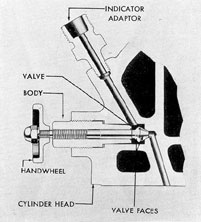
d. Cylinder test valve. The cylinder test
valve is located in the cylinder head and is
made up of a valve body which is screwed into
the cylinder head, and a valve stem which has
a threaded fit in the body and a handwheel at
the outer end. The valve itself has two faces,
an inner face and an outer, or secondary, face.
From the valve seat two passages are bored in
the cylinder head casting, one leading to the
inside of the cylinder and the other leading to
the outside. This outside connection is fitted
with an indicator adapter which is used when
a pressure indicator reading is taken of hot or
cold compression pressure. When the handwheel
is in the closed position, the inner valve face
seats against the main valve seat, closing the
passage to the combustion chamber, and preventing the pressure in the cylinder from escaping to the outside. If the handwheel and valve
stem are open, the passage to the outside is
connected to the passage to the inside of the
cylinder. When the valve stem is at its full open
position, the outer or secondary valve face bears
against the valve body, thus preventing the passage of exhaust gases through the valve body.
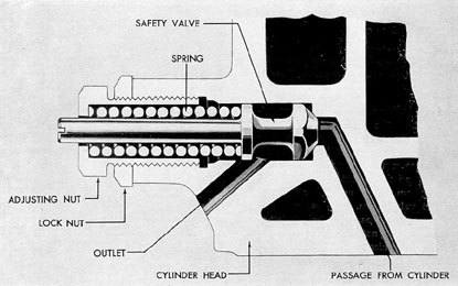
e. Cylinder relief, or safety valve. Each
cylinder head is equipped with a safety valve
(Figure 3-29) which opens if the cylinder pressures exceed a safe operating limit. This valve
head is machined to fit the valve seat and opens
or closes a passage leading from the combustion
chamber to the outside of the cylinder. The
valve face is held against the valve seat by a
pressure spring. Tension on the spring is varied
with an adjusting nut and locked when the
desired setting is attained. This setting varies
with the type of engine and may be found by
referring to manufacturers' instruction books. If
the pressure in the cylinder exceeds that set on
the valve spring, the valve will open and remain
open until the pressure in the cylinder is less
than the spring pressure, at which point the
valve will close.
Figure 3-28. Cylinder test valve, GM.
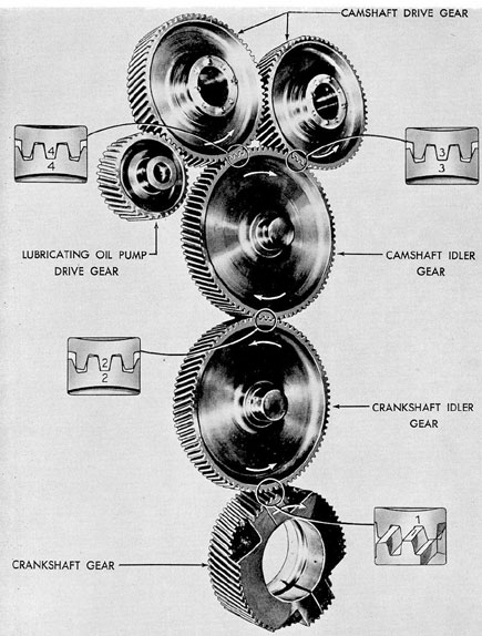
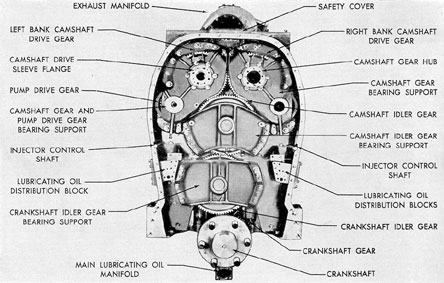
f. Camshaft drive. The camshafts are
driven from the control end of the crankshaft
through a train of helical spur gears, with a
crankshaft idler gear and a camshaft idler gear
between the two camshaft gears and the crankshaft gear. The camshafts run at the same speed
as the crankshaft but in the opposite direction
of rotation. The drive gear for the lubricating
oil pump is driven from the left bank camshaft
gear in a left-hand rotation engine and from
the right bank camshaft gear in a right-hand
rotation engine. All of the other gears are in
the same location regardless of rotation. These
gears are made of steel forgings.
55
Figure 3-29. Cylinder relief or safety valve, GM.
The split crankshaft gear is mounted loose
on the crankshaft and held together with clamping bolts. The bore of the crankshaft gear is
babbitted and a circumferential groove in the
bearing forms the thrust surfaces which bear
against a collar on the crankshaft. The crankshaft gear is driven through a spline ring on
the elastic coupling.
Each of the two idler gears and the lubricating oil pump drive gear are mounted on a
heat-treated steel shaft, which is pressed into the
gear hub. The two idler gear shafts are supported in inner and outer bearing supports fitted
with single-flanged steel bushings, which are
lined with babbitt. The bearing supports are
accurately aligned with dowel pins and fastened together with studs. The pump drive gear
is supported in the bearing supports of the
mating camshaft gear.
The hub projections on the outside of the
camshaft gears are finished to form journals, and
are supported in babbitt-lined steel bushings
which are pressed in the inner and outer bearing supports. The inner and outer bearing supports are accurately aligned with dowel pins
and are fastened together with studs. The gear
and bearing support assemblies are located accurately in the camshaft drive housing with
dowels and fastened with studs.
The outer flange of each camshaft driving
sleeve is fastened to the outer face of the camshaft gear hub by capscrews. The inner end of
the driving sleeve is flanged and doweled to
the flanged end of the camshaft. The camshaft is
driven through the dowel pins in the connection, and a bolt, smaller than the dowel pins,
prevents incorrect assembling of this drive connection. The holes in the outer flange of the
driving sleeve are slotted, so that the camshaft
may be accurately adjusted to the correct timing position. When this adjustment has been
made, the timing position is permanently fixed
by dowel pins, through which the driving sleeve
and the camshaft are driven.
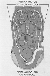
Oil for lubricating the gear teeth and the
gear bearings is received from two oil-distributing blocks in the camshaft drive housing. The
two distributing blocks are supplied with oil
from the main manifold in the oil pan. The
engaging gear teeth are lubricated with jets of
oil delivered through tubes and nozzles. The
outer bearings of all the gears, except the
56
Figure 3-30. Camshaft drive gears, GM.
57
Figure 3-31. Camshaft drive assembly, GM.
Figure 3-32. Camshaft drive lubrication, GM.
crankshaft gear, receive lubricating oil through tubes
and drilled holes in the outer bearing supports.
The inner bearings are lubricated with oil that
is received from the outer bearings, through
holes drilled in the gear hubs.
The gear train is enclosed in an oiltight
housing. The housing is accurately located on
the end of the crankcase with dowel pins and
is held in place with studs, some of which
secure both the housing and the gear assemblies.
A pressure relief opening in the top of the
housing is fitted with a spring-loaded plate.
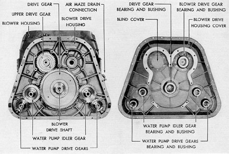
g. Accessory drive. The accessory drive is
located on the blower end of the engine and
consists of a train of helical gears transmitting
the rotation of the crankshaft to the blower and
water pumps. The gears are enclosed in a case
bolted to the blower housing.
The blower and accessory drive gear, which
drives the water pump idler gears and the
blower drive gear, is driven from the crankshaft
through a splined shaft, one end of which fits
into a hub that is bolted to the crankshaft, while
the other end fits into the blower drive gear
hub. The water pump drive gears are driven by
58
Figure 3-33. Accessory drive assembly with cover, GM.
the idler gears. All gears are steel forgings and
have integral shafts. The inner gear bearings are
babbitt lined, with integral thrust faces and
are pressed into the housing. The outer bearings
are pressed into the housing cover plates,
which are bolted to the accessory drive cover.
Oil for lubricating the gear bearings is
received from a manifold bolted to the main
lubricating oil manifold, which carries oil to
passages formed by steel tubing cast into the
ribs of the drive housing. The outer bearings
are lubricated by oil flowing through passages
in the gear hubs.
D. FAIRBANKS-MORSE ENGINE COMPONENTS
3D1. General. Descriptions of engine components in this section apply only to the Fairbanks-Morse 9- and 10-cylinder engines.
3D2. Main stationary parts. a. Cylinder
block. The cylinder block is the main structural
part of the engine and is designed to give the
engine the necessary strength and rigidity. It is
constructed by welding various structural members and bracings into one unit. The transverse
vertical members together with four horizontal
decks farm the enclosures and housings for the
various operating or functional parts. The four
horizontal decks are bored to receive the cylinder liners along the axis of the engine.
The cylinder block consists of the following compartments:
1. Control end compartment, forming an
enclosure for the timing chain, controls, and
flexible gear drive for the attached pumps and
governor.
2. Vertical drive compartment, forming
the enclosure for the bearing assembly housings
of the vertical drive shaft connecting the upper
and lower crankshafts.
3. Upper crankshaft compartment,
59
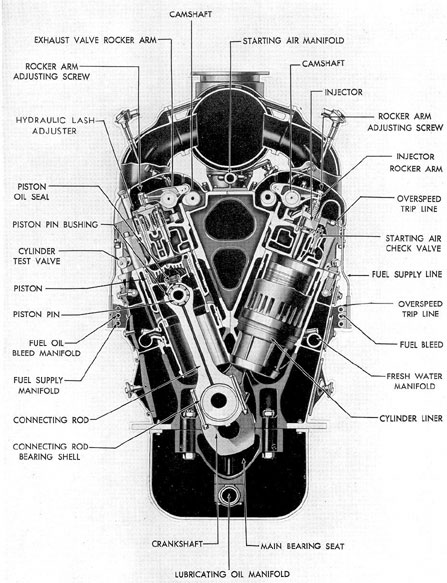
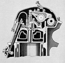
Figure 3-34. Cross section of F-M 38D 8 1/8 engine.
forming the bearing saddles for the upper crankshaft
bearings and hubs for the bearings of the two
camshafts.
4. Scavenging air compartments and air
receivers running lengthwise on each side of the
cylinder block, forming a passage for scavenging
air to the inlet ports of the cylinders.
5. Valve compartments, forming enclosures
for the injection nozzles, injection pumps, air
start check valves, cylinder relief valves, and
governor control shafts.
6. Exhaust manifold and belt compartment,
extending lengthwise on each side of the cylinder block. With the installation of the exhaust belt and two exhaust manifolds in this
compartment, a passage is formed for the exhaust gases from the cylinders to the external
exhaust system.
7. Lower crankcase compartment, forming
the bearing saddles for the lower crankshaft
bearings.
The block is sand blasted after welding. It
is then stress relieved by seasoning in an
electric furnace to remove most of the internal
strains introduced by welding. Lastly, it is magnafluxed to check the welding at all welded
joints.
The air receiver, vertical drive, and control
end compartments are provided with covers.
The upper crankcase compartment is closed
with a sheet metal top cover having several
small inspection covers over the cylinders.
These inspection covers are spring loaded so
that in an emergency undue pressure in the
crankcase compartment will be relieved. One
of the vertical drive compartment access plates
is spring loaded for the same purpose.
b. Cylinder liner. The cylinders are bolted
into the cylinder block in a row along the centerline of the engine. They are spaced so that
the lower end will enter the bored hole in the
exhaust belts. The spacing must be horizontally
correct so that the pistons and connecting rods
coincide with the throws of the crankshafts.
No. 1 cylinder is always at the control end of the
engine.
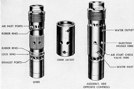
Figure 3-38. Cylinder liner, F-M.
62
The complete cylinder consists of an inner
cast iron liner fitted into a steel jacket. The
jacket extends over the high-pressure, high
temperature part of the liner and helps to reinforce the area of greatest stress. Between the
inner liner and the jacket is a space for cooling
water. Cooling water enters through an elbow
connection near the bottom on each side of the
steel jacket and leaves through a pipe connection near the top of the steel jacket. The upper
and lower circumferences of the water cooling
passage between the liner and the jacket and
the pipe connections at the inlet elbows of the
liner are made watertight with synthetic rubber seal rings. A lock ring is also installed to position the steel jacket over the liner and prevent any movement between the liner and
jacket due to expansion from the heat of engine operation.
The tangentially shaped scavenging air inlet ports are located near the top of the liner and
are opened and closed by the upper piston. The
exhaust ports are located near the bottom of the
liner and are opened and closed by the lower
piston. Each cylinder liner has four valve ports
bored near its center for two injection nozzles,
an air start check valve, and a cylinder relief
valve with indicator cock which are adapted
together.
Circular ribs or radiating fins are provided
near the top of the liner to allow the scavenging
air to carry away some of the heat of combustion. Vertical ribs in the liner between the inlet
and exhaust ports direct the water travel upward, absorbing heat from this part of the
cylinder. The liner is bolted to the top deck
of the cylinder block by means of lugs. The
liner is held rigid at this point and any expansion of the liner due to the heat of combustion
is downward through the counterbores of the
engine framing and exhaust belts. Tapped holes
for lifting eyebolts are also provided in the lugs
that bolt the liner to the cylinder block.
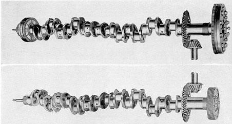
3D3. Main moving parts, Fairbanks-Morse.
a. Crankshafts. Each Fairbanks-Morse engine
has an upper and a lower crankshaft. The upper
pistons are connected to the upper crankshaft
and the lower pistons are connected to the lower
crankshaft. Both crankshafts are of the integral
type, constructed of machined, fine grain cast
iron, dynamically balanced. The lower crankshaft is connected to the generator by means
of the crankshaft flexible coupling. The upper
crankshaft is connected to the lower crankshaft
by a vertical drive shaft assembly and bevel
gears. As the lower crankshaft leads the upper
crankshaft by about 12 degrees, it is found
that the lower cylinders develop about 72 percent of the power at rated load and the upper
cylinders about 28 percent of the power. As
the upper crankshaft also drives the scavenging air blower and other auxiliaries, a relatively
small percentage of the total power is transmitted from the upper crankshaft through the
vertical drive shaft to the lower crankshaft.
Both crankshafts on the 10-cylinder engine
have ten cranks. The 9-cylinder engine has two
crankshafts, each having nine cranks. Main
bearing and connecting rod journals are stone
ground to a smooth finish. Weight and bearing
loads are reduced by hollow casting the shaft
and crankpins. Oil passages are drilled so as to
permit lubricating oil to be forced from each
main bearing journal to the adjacent crankpin
journals.
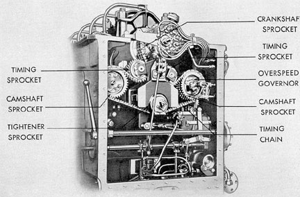
The crankshaft sprocket for the timing
chain drive is keyed to the upper crankshaft at
its control end. The air start distributor camshaft is also fastened to the upper crankshaft at
the control end. At the opposite or blower end,
the blower flexible drive gear is keyed and held
with a retainer plate to the crankshaft.
The torsional damper is keyed to the control end of the lower crankshaft and secured by
means of a key and a damper hub nut. The
flexible pump drive gear for driving the governor and attached pumps is keyed to the torsional damper spider. The flexible crankshaft
coupling driving gear is bolted to a flange on
the blower end of the lower crankshaft.
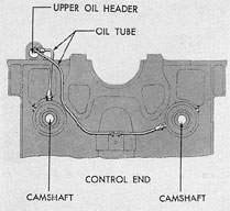
b. Main bearings. Main bearings in the
upper and lower crankcase support the upper
and lower crankshafts. Each main bearing consists of an upper and lower precision made bearing shell that is lined with Satco metal. The
upper and lower shells fit into the enclosures
formed by the saddles or bearing seats in the
cylinder block and the bearing caps. The bearing caps are made of forged steel. They are assembled with the bearing saddles in the cylinder
block and bored in line to give precision alignment and close fit to the bearing shells. Both
bearing caps and saddles are finished for a close
fit and form the bearing seats of the bearing
shells. The bearing caps are located in the
cylinder block by dowels and held by two bolts
with castle nuts and cotter pins on each end.
The locating dowels also prevent side and end
play in the bearing cap. The upper and lower
bearing shells are doweled together and marked
for proper location on the edge toward the control end of the engine. The bearing shells housed
in the bearing caps have dowel pins that prevent the bearing shells from rotating.
Both upper and lower bearing shells have
oil grooves around the center of the inside surface. The bearings are lubricated by oil under
pressure from the engine pressure system. The
oil is piped to the bearing caps through lines
from the main oil header and fed through holes
into the grooves where it lubricates the bearing
surface. Oil is conducted through oil passages
in the crankshaft to the connecting rod journals
and bearings. Crankshaft thrust is taken by a
thrust bearing located at the blower end of each
crankshaft. The bearing shells of the thrust
bearings are similar to the regular main bearing
shells except that they have enlarged flanges
with bearing metal extending over the flanges
to take the thrust. Slots and a drilled passage
conduct oil to the thrust surfaces.
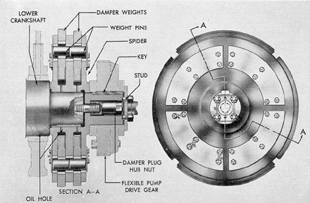
c. Torsional damper. Every crankshaft with
attached rotating parts has a natural period of
torsional vibration, the frequency of which depends upon the mass and elasticity of the shaft
and of the parts attached to it.
If turning impulses are applied to the shaft
at regular intervals, and if their frequency of application is a multiple of the natural frequency
of the shaft, a condition of synchronous torsional
vibration is produced. This condition is not usually found in the F-M 9-cylinder engine but is
definitely present in the F-M 10-cylinder engine. The points at which it occurs are known as
the critical speeds.
If the engine is to be permitted to run at
one or more of these critical speeds, a means of
damping the torsional vibration is advisable.
Otherwise the amplitude of the vibration may
become great enough to cause breakage of the
crankshaft.
The torsional damper is mounted on the
lower crankshaft at the control end of the F-M
10-cylinder engine. This unit consists of a spider
fitted with eight damper weights. These are installed in two rows in slots in the spider. Each
weight is located and free to move in or out on
the two weight pins, according to the speed of
rotation of the crankshaft. Lubrication is furnished to the moving parts of the damper from
the engine pressure system by means of grooves
and holes in the spider hub.
In addition to the torsional damper, it is
necessary to devise a method of preventing torsional vibrations between the crankshafts and
the various auxiliary drives. This is usually done
by means of flexible drive gears in each auxiliary
gear train and by a flexible spring coupling in
the vertical drive shaft.
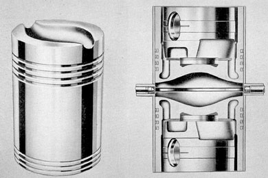
d. Pistons and piston rings. The upper and
lower pistons of the F-M diesel engines are
similar, but are not interchangeable because of the
position of the injector nozzle grooves in the
piston crown. The pistons are made of closely
grained cast iron and are tin plated. Each piston
has four compression piston rings near the
crown end. One oil control ring and two oil
drain rings are located near the piston skirt. The
oil control ring controls lubrication of the
cylinder wall, and the oil drain rings prevent
excessive lubrication of the cylinder wall. The
amount of oil on the cylinder walls is also controlled by a row of small, drilled holes at the
skirt end of the piston. These holes allow the
lubricating oil to escape and drain to the crankcase through the piston wall after the piston
rings have scraped it off the liner. They also
prevent excessive pressure being built up behind
the oil rings, thereby cutting down the amount
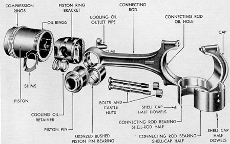
of ring wear. The piston pin fits into a cast steel
piston pin bracket which is in turn bolted to the
main piston. The pistons are cooled by oil under
pressure from the engine lubricating system. The
oil is forced into the oil cooling chambers under
Figure 3-42. Torsional damper, F-M.
66
Figure 3-43. Pistons, F-M.
the piston crown. This oil drains out of the
piston by means of a cooling oil outlet pipe
which is set at an angle and jets the outlet
stream of oil so that it follows the throw of the
crank, thereby keeping the hot oil from splashing on the connecting rod bearing and cylinder
liner and preventing excessive churning and
frothing of the oil. The compression rings are
gold seal. These are made of cast iron and have
a small bronze insert in a slot around the face
of the ring. The bronze insert protrudes slightly
beyond the surface of the face part of the ring.
They are used because the bronze, being a softer
metal, makes the ring conform more rapidly to
the already worn-in cylinder wall than would
an all cast iron ring. This shortens the wearing
in time of a new ring.
e. Piston pin assembly. Connection between the piston and connecting rod is made by
the piston pin and the piston pin bracket. The
latter is bolted inside the piston, clamping the
piston pin tightly and forming an enclosure for
the piston cooling oil.
The piston pin fits into the bores in the
piston pin bracket which is bolted to the inside
of the main piston and holds the piston pin in
place. Thus there is no possibility of loose piston
pins damaging the cylinder walls. The bearing
receives oil through holes in the connecting rod
bushing which are aligned with the oil groove
in the upper connecting rod eye.
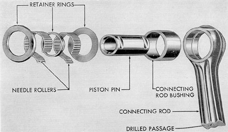
There are two types of piston pin bearings.
The sleeve bearing, or bushing type of piston
pin bearing, consists of a cast bronze lining
pressed into the steel bushing in the connecting
rod eye. Lubrication is supplied by oil holes in
the steel bushing which line up with the drilled
oil hole in the connecting rod. Grooves on the
surface of the lining distribute oil over the bearing surface.
The F-M 9-cylinder diesel engines were
originally equipped with a needle roller type
piston pin bearing instead of the bushing type
of bearing. However, replacements for this assembly are of the plain bushing type. In the
roller bearing type the inner race is formed by
67
Figure 3-44. Piston rings, F-M.
the case-hardened steel piston pin. There are
two rows of hardened steel needle rollers with
43 rollers in each row. The rows are separated
by three retainer rings. The outer race of the
bearing is formed by the case-hardened steel
bushing that fits into the eye of the connecting
rod.
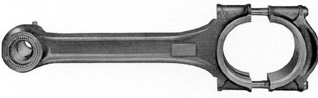
f. Connecting rods and connecting rod
bearings. The construction of the upper and
lower connecting rods is basically the same except that the lower connecting rod is longer
than the upper connecting rod. The connecting
rods are made of alloy steel forgings. The rods
are forged in an I-section with a closed eye at
the piston end to receive the piston pin bearing
and a removable cap at the crank end which
encloses the connecting rod bearing shells. The
cap is secured to the rod by two bolts, castle
nuts, and cotter pins.
The connecting rod bearing is made up of
upper and lower bearing shells. These are bimetal precision type bearings with machined
bronze or steel backs and with a centrifugally
cast soft lining of Satco metal, a high lead bearing metal. Both bearing shells are kept from
rotating by dowel pins in the cap and bearing
Figure 3-45. Needle roller type piston pin assembly, F-M.
68
seats. Oil is forced under pressure through holes
in the bearing shell to the grooves on the inner
surface of the bearing shell and to the oil passage in the connecting rod shaft. Bearing shells
are marked on the outside of one flange with
the number of the connecting rod. Shells should
be installed with the markings placed toward
the control end of the engine.
g. Vertical drive. On Fairbanks-Morse
opposed piston engines the upper and lower
crankshafts are connected at the blower end
of the engine by a flexible, vertical drive shaft
(Figure 3-48). A portion of the power of the
upper crankshaft is expended in driving accessories and in driving the blower. The remaining
power of the upper crankshaft is delivered
through the vertical drive shaft to the lower
crankshaft of the engine. Gears and bearings on
Figure 3-46. Connecting rod with needle roller type piston pin bearing, F-M.
Figure 3-47. Connecting rod and piston assembly, F-M.
69
Figure 3-48. Assembled view of crankshaft vertical drive on 10-cylinder F-M engine.
70
the vertical drive shaft are lubricated directly
from the main engine lubricating systems
through tubes leading from the riser duct connecting the upper oil header to the lower oil
header.
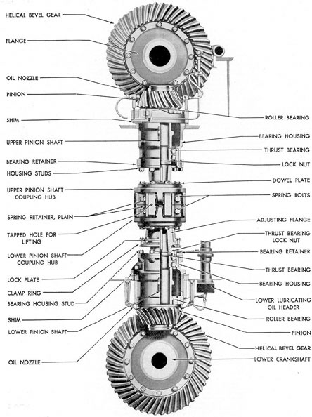
The 9- and 10-cylinder engine vertical
drives differ in construction. In the 10-cylinder
engines, helical bevel gears or ring gears are
bolted to flanges on both the upper and the
lower crankshafts. Each of the ring gears meshes
with a helical bevel pinion. Each of the pinions
is fitted and keyed to a vertical pinion drive
shaft. The two pinion shafts rotate in roller and
thrust bearings located in the upper and lower
drive housings. These housings are bolted to the
horizontal decks of the cylinder block.
The inner ends of the pinion drive shafts
are keyed to coupling hubs. The upper and
lower pinion shaft coupling hubs are connected
together by means of a flexible coil spring coupling
unit having an upper and lower coupling
hub and an adjusting flange, or cone coupling as
it is sometimes called. The upper pinion shaft
coupling hub bolts directly to the flexible
spring coupling upper hub. The lower pinion
shaft coupling hub is connected to the lower
flexible spring coupling hub through the adjusting flange.
Thus the upper and lower pinion shafts are
connected by a spring-loaded flexible coupling
which consists of upper and lower members between which are housed 16 coil springs held by
retainers. Torque on the upper hub of the flexible coupling is passed to the coil springs which
in turn apply torque to the lower hub of the
flexible coupling. Thus the coupling has torsional
flexibility which permits it to absorb crankshaft
torsional vibrations.
The flexible spring coupling also has a certain amount of vertical flexibility to allow for
expansion due to operating temperatures. It has
sufficient flexibility to account for a small
amount of misalignment between the upper and
lower pinion shafts.
The adjusting flange serves as a means of
disconnecting the vertical drive so that the
crankshafts may be turned separately for servicing. It is clamped to a tight fit over the tapered
lower pinion shaft coupling hub by means of a
clamp ring and retains a fixed relation between
shafts by means of intermediate lock plates and
friction between the two cone, or tapered, surfaces. It permits an unlimited adjustment of timing to achieve an exact 12-degree crank lead of
the lower crankshaft. Timing of the crankshafts
for the 12-degree lead of the lower crankshaft
is achieved by setting the crankshafts before
clamping, then locking the clamp ring and installing the lock plates.
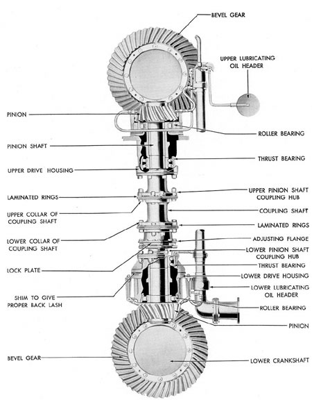
The 9-cylinder Fairbanks-Morse vertical
drive and the 10-cylinder vertical drive use a
flexible coupling, which consists of a coupling
shaft with upper and lower collar, and which
has a set of laminated saw steel rings at each
end. Each laminated group consists of 30 to 40
rings, each .019 inch thick. The set, when installed and compressed, is about 5/8 inch thick.
The upper pinion shaft coupling hub and the
upper collar of the coupling shaft are bolted to
the laminated rings at different points. The
lower collar of the coupling shaft and the upper
collar of the adjusting flange are bolted to the
lower set of laminated rings at different points.
The vertical flexibility of the coupling through
the laminated rings allows variations due to expansion of the engine. In addition some of the
Fairbanks-Morse 10-cylinder engines use a coil
spring type of flexible coupling.
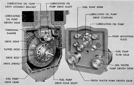
h. Flexible drive far auxiliaries. The fresh
water and sea water circulating pumps, the attached fuel oil and lube oil pumps, and the
Woodward governor are all driven from the
lower crankshaft through a flexible gear drive
at the control end.
In this drive, power is transmitted through
springs which absorb shocks inherent in the engine and transmitted by the lower crankshaft.
The two circulating water pumps are driven directly from the flexible gear through their
driven gears. The fuel oil pump drive gear and
idler gear in turn rotate the fuel oil pump driven
gear. The lubricating oil pump driven, gear and
drive shaft drive the pump by means of a coupling meshing with slots in the end of the shaft.
A bevel gear, mounted on the lubricating
oil pump drive shaft, meshing with a mating
gear on the governor drive shaft, drives the governor through the governor coupling shaft The
ball bearings and gears of the governor drive
are lubricated with oil thrown off from the
71
Figure 3-49. Assembled view of crankshaft vertical drive on 9-cylinder F-M engine.
72
Figure 3-50. Flexible drive with housing cover removed, F-M.
Figure 3-51. Camshaft cross section showing control end of both camshafts, F-M.
73
timing chain in the control end compartment. The
flexible drive is lubricated by oil forced through
the crankshaft to the flexible drive gear, oil
dropping from the Woodward governor drive
Figure 3-52. Camshaft lubrication, F-M.
shafting, and returning oil from the upper crankcase.
3D4. Valves and valve actuating gear. a.
Camshaft. The Fairbanks-Morse engine has two
camshafts which are located in the upper crankshaft
compartment. The function of the camshafts
is to actuate the two fuel injection pumps
at each cylinder in exact unison and at the
proper time.
Both camshafts are made of steel and each
consists of three or four sections flanged and
bolted together. The cams are forged integral
with the camshaft and then ground to a master
camshaft. The sections are match-marked so
that they may be connected in proper relationship
to each other. The camshafts may be removed
a section at a time or in one unit. There
is one cam for each cylinder on each camshaft.
Each camshaft is operated by a sprocket bolted
to a flange on the control end of the camshaft.
Both camshaft sprockets are driven by one timing
chain so that proper timing between the two
camshafts is maintained.
Figure 3-53. Timing chain, F-M.
74
Each camshaft operates in bearings located
at each vertical member or crosswebbing of the
cylinder block. Camshaft thrust is taken by a
thrust bearing located at the blower end of the
camshaft. The camshaft bearings are of the
split sleeve type, the upper and lower shells consisting of steel backs with soft metal or babbitt
linings. The bearings are located and held in
place by setscrews. The two halves are held together by snap rings.
The camshaft bearings are lubricated by
oil from the upper lubricating oil header. The
oil is led through oil tubes to the control end
bearing of each camshaft. Oil enters the bearing
cap, is forced through a hole in the bearing
shell and camshaft journal to the hollow bore of
the camshaft. It is then forced through radial
drilled holes to each of the bearings along the
entire camshaft. Oil holes in the hubs at the
driving ends of the camshafts connected with
the holes in the camshaft sprockets provide oil
for the timing chain. The overspeed governor is
mounted at the control end of the left-hand
camshaft in the left-hand rotation engines and
on the right-hand camshaft in right-hand rotation engines.
Figure 3-54. Timing chain details, F-M.
Figure 3-55. Timing chain link, F-M.
b. Camshaft drive. Both camshafts are
driven by one endless type timing chain connecting the crankshaft sprocket with the camshaft drive sprockets. The crankshaft sprocket
is attached to the upper crankshaft at the control end of the engine. The camshaft sprocket is
attached to the end of each camshaft.
The endless timing chain passes over the
crankshaft sprocket, under two opposed timing
sprockets, over the two camshaft drive sprockets,
and under a chain tightener sprocket. The two
timing sprockets are mounted on a timing
bracket. The timing bracket has an 8-degree
pitch adjustment. Moving the timing bracket
arm moves both timing sprockets on the chain
at once, changing the camshaft relation to the
crankshaft. Thus the chain is tightened in operation between the crankshaft sprocket and one
camshaft drive sprocket, and given more slack
between the crankshaft sprocket and the other
camshaft drive sprocket. This provides a precision adjustment for securing the exact phase
relation desired between the crankshaft and two
camshafts. The tightener sprocket is adjustable
to secure the proper slack in the chain.
The timing chain is assembled as shown in
Figure 3-53. The guide links for guiding the
chain on the timing sprockets and tightener
sprocket ride in slots in the crankshaft and camshaft drive sprockets.
c. Cylinder relief and indicator valves.
Each cylinder in the engine is fitted with a
water-cooled, automatic relief valve for the out
let of excessive pressures in the combustion
space. The relief valves are normally set to open
at about 2,000 psi, and to close as soon as the
pressure has dropped below this setting.
The relief valve is threaded into the
adapter valve which also has a tapped opening
for an indicator valve. The complete assembly
is attached to a cylinder liner valve adapter
sleeve by means of a threaded collar and stud
nuts.
The relief and indicator valve adapter
sleeve is cooled by water which is admitted to
the adapter water jacket through a groove machined on the outside of the cylinder liner.
The indicator valves are threaded and
screwed permanently into the cylinder relief
valve adapters. When a pressure reading is to be
75
Figure 3-56. Cylinder relief valve, F-M.
Figure 3-57. Cylinder relief valve and adapter, F-M.
Figure 3-58. Indicator valve, F-M.
76
taken, the pressure indicator is screwed on the
end of the indicator valve. Opening of the valve
backs a beveled collar seat on the valve stem
against a beveled seat on the valve gland and
closes small vent holes in the valve body. Pressure is then free to pass to the indicator without
leakage and burning of the valve stem which is
not packed.
As the indicator valve is closed, the beveled
collar is forced against the other seat in the inlet port, and the pressure in the indicator is free
to escape through the vent holes in the valve
body.
77
GENERAL MOTORS
ENGINE DATA, RATINGS, AND CLEARANCES
MAIN ENGINES
AUXILIARY ENGINE
Model number
16-278A
16-248
8-268
Number of cylinders
16
16
8
Bore and stroke
8 3/4 x 10 1/2
8 1/2 x 10 1/2
6 3/8 x 7
Brake horsepower (continuous)
1600
1600
437
Generator output
1134 kw
1134 kw
300 kw
Rated engine speed
750 rpm
756 rpm
1200 rpm
BMEP (continuous)
83.6 psi
88.6 psi
80.7 psi
Type of engine
2 cycle
2 cycle
2 cycle
Cylinder arrangement
40 degrees "V"
40 degrees "V"
In line
Cylinder firing order for left-hand rotation
1-9-8-16-2-10- 6-14-4-12-5- 13-3-11-7-15
1-9-8-16-2-10- 6-14-4-12-5- 13-3-11-7-15
1-6-5-2- 8-3-4-7
Cylinder firing order or right-hand rotation
1-15-7-11-3- 13-5-12-4-14- 6-10-2-16-8-9
1-15-7-11-3- 13-5-12-4-14- 6-10-2-16-8-9
Starting system
Air
Air
Air
Injection system
Mechanical
Mechanical
Mechanical
Scavenging
Uniflow
Uniflow
Uniflow
Operating Pressures of Full Load and Speed
Lub. oil-cooler to engine
40-50 psi
50 psi
35-45 psi
Fuel oil to injectors
40-50 psi
35 psi
50-60 psi
Sea water-pump to coolers
15-35 psi
34 psi
10-40 psi
Fresh water-pump to engine
18-35 psi
31 psi
15-28 psi
Starting air pressure to engine
500 psi
500 psi
500 psi
Operating Temperatures at Full Load and Speed
Max. exhaust at 3" Hg. back pressure
550-650 degrees F
670 degrees F
650 degrees-750 degrees F
Lubricating oil-engine to cooler
Range
140-180 degrees F
138 degrees-147 degrees F
140 degrees-180 degrees F
Preferred
170 degrees
F 145 degrees F
170 degrees F
Lubricating oil-from cooler
130-160 degrees F
114 degrees-119 degrees F
120 degrees-155 degrees F
Fresh water-engine to cooler
Range
140 degrees-170 degrees F
150 degrees-154 degrees F
140 degrees-180 degrees F
Preferred
160 degrees F
160 degrees F
160 degrees F
Fresh water-from cooler
105 degrees-130 degrees F
130 degrees-134 degrees F
115 degrees-135 degrees F
Sea water temperature rise through fresh water cooler
10-20 degrees F
17-19 degrees F
10-25 degrees F
Pressure Relief Valve Settings
Lubricating oil regulating
At full load and speed
40-50 psi
At 375 rpm - no load
8-12 psi
Lubricating oil at engine
50 psi
50 psi
35-45 psi
Fuel oil to injectors
40-50 psi
35 psi
50-60 psi
Miscellaneous
Overspeed trip setting
802 rpm
805 rpm
1350 rpm
Torque limits for bolts, studs-ft lb
Cylinder head studs
650
325
Connecting rod bolts
100
70
Main bearing bolts
550
300
Cylinder liner studs
175
78
Clearances of General Motors Principal Parts (in Inches)
Main Bearing
Model 278A
Model 248
Model 268A
Model 268
Shell to Shaft Clearance (New)
.006-.009
.006-.009
.0035-.0065
.0035-.0065
Shell to Shaft Clearance-Max. Allowable (Worn)
.030
.030
.020
.020
Min. Allowable Shell Thickness (Worn)
.3601
.360
.240
.240
Thrust Bearing End Clearance-New
.030-.035 .118-.125
.030-.035
.010-.013
.010-.013
Thrust Bearing End Clearance-Max. Allowable (Worn)
31
.050
.025
.025
Connecting Rod
Shell to Shaft Clearance-New
.0065-.0085
.0065-.0085
.0025-.0065
.0025-.0065
Shell to Shaft Clearance-Max. Allowable (Worn)
.025
.025
.010
.010
Min. Allowable Shell Thickness (Worn)
.2381
.2381
.180
.180
Min. Allowable Piston Pin Dia. (Worn)
2.992
2.99266
2.620
2.620
Min. Allowable Piston Pin Bushing-Outer Dia. (Worn)