1A1. General. In order that the function
and operation of submarine diesel engines may
be thoroughly understood, it is necessary to describe briefly the history and development leading to modern design.
It is significant that the diesel engine is an
outgrowth of the early struggle to improve the
efficiency of existing types of other internal
combustion engines. Today's fleet type submarine diesel engines are indirectly the result of
widespread experimentation in both the Otto
(gasoline) engine field and the more recently
developed diesel engine field. Basically, however, the principles of operation have not
changed materially since the first practical models of the early designs.
Among the contributors to progress in the
development of diesel engines has been the
Submarine Service of the United States Navy.
Keen interest and untiring effort, not to mention
risk in experimentation, testing, and correcting
design, have given unparalleled impetus toward improved design.
1A2. History of diesel engine development.
The reciprocating internal combustion engine
was introduced in theory as far back as 1862
by Beau de Roches in France. A few years later,
Otto, of Germany, made the first practical application of Beau de Roches's theory in an
actual working model. Otto's engine was practicable and fairly reliable compared to other
earlier attempts. It employed a 4-stroke cycle
of operation using gas as a fuel. Thus, the
4-stroke cycle of a gas engine became popularly
known as an Otto cycle.
George Brayton, an American, introduced
a new principle of fuel injection in 1872. Brayton used an internal combustion gas engine in
his experiments. He demonstrated that prolonging the combustion phase of the cycle, by injecting fuel at a controlled rate, produced more
power per unit of fuel consumed. However,
much of the efficiency gained by this method
was lost due to the lack of an adequate method
of compressing the fuel mixture prior to ignition.
The next notable achievement in improving the efficiency of the internal combustion
engine was the Hornsby-Ackroyd engine produced in England a short while later. It was
among the first early designed engines that
used a liquid fuel derived from crude oil. This
engine employed the Brayton principle of controlled fuel injection and compressed the air
in the cylinder prior to ignition. The compression heat thus generated, plus the use of a hot
surface, induced ignition. Since this engine employed hydraulic force to inject the fuel, it is
now considered the first example of an engine
using mechanical or solid injection.
In 1893, Dr. Rudolf Diesel, a Bavarian
scientist, patented a design for an internal combustion engine which was termed a Diesel
engine. He considered previous failures and
applied himself to designing an engine to operate on an entirely different thermodynamic
principle.
Using the mechanics of the 4-stroke cycle,
Dr. Diesel proposed that only air be drawn
into the cylinder during the suction or intake
stroke. The compression stroke was to compress
the air in the cylinder to a sufficiently high
temperature to induce ignition and combustion
without the use of added heat. Like Brayton's
engine, this engine was to inject fuel at a controlled rate. It was Dr. Diesel's theory that if
the rate of injection were properly controlled
during the combustion phase, combustion could
be made to occur at a constant temperature.
Since fuel would have to be injected against
high compression pressures in the cylinder, Dr.
Diesel's design called for fuel injection to be
accomplished by a blast of highly compressed
air. Essentially, this was air injection. Dr. Diesel
further theorized that the temperature drop
during the expansion phase of the cycle would
be efficient to make external cooling of the
combustion chamber unnecessary.
A single-cylinder working model was constructed and first experiments were conducted
using coal dust as a fuel. All efforts to operate
1
a working model on the cycle proposed by Dr.
Diesel resulted in explosions and failure. Further
attempts to experiment along this same line
were abandoned. Consequently, an engine operating entirely on the theoretical cycle proposed by Dr. Diesel was never produced. This
cycle subsequently became known as the diesel
cycle.
Many designers realized the value of the
practical elements in the cycle of operation
outlined by Dr. Diesel. Subsequently, experimenters began to achieve favorable results by
eliminating the impractical elements and by
altering the cycle of operation. Successful experiments were conducted by the Machinen-fabrik-Augsburg-Nurnberg (commonly called
MAN) concern in Germany.
By this time the more volatile petroleum
fuels were in common use and diesel engines
utilizing liquid fuel were designed. These engines operated on a cycle in which the combustion phase occurred at constant pressure
rather than at constant temperature. Experience
also disclosed that it was essential to cool the
combustion chamber externally. Early diesel
engines operating on the constant pressure
cycle, were efficient enough to make commercial production feasible.
Progress in diesel engine design has been
rapid since the early models were introduced.
The impetus of war demands, progress in metallurgy, fabrication, and engineering, and refinements in fuels and lubricants have all served
to produce modern, high-speed diesel engines
of exceptional efficiency.
1A3. History of submarine engine development. The first United States submarines utilizing internal combustion engines for propulsion were powered by 45-horsepower, 2-cylinder,
4-stroke cycle gasoline engines produced by
the Otto Company of Philadelphia. Meanwhile,
the English Submarine Service made use of
12- and 16-cylinder gasoline engines in their
earlier submarines.
The inherent hazards accompanying the
use of such a highly volatile fuel as gasoline
were quickly realized. Stowage was a constant
problem and handling of the fuel was extremely
dangerous. Internal explosions were frequent
and, in addition, many of these engines gave
off considerable carbon monoxide fumes, creating a menace to personnel.
In the meantime, MAN built and experimented with 2-stroke cycle diesel engines for
submarine propulsion. However, insufficient
progress had been made in metallurgy to provide metals capable of withstanding the greater
heat and stress inherent in engines of this type.
MAN then turned its efforts toward production
of a 4-stroke cycle diesel engine capable of developing 1000 hp. While fairly successful, these
engines eventually developed structural weaknesses at the crankcase.
By 1914 the MAN 4-stroke cycle diesel
had been partially redesigned and strengthened,
producing the SV45/42, 1200-hp engine used
in the majority of German submarines during
World War I. Following World War I, the
United States Navy acquired a number of these
engines for use in the earlier S-class boats. A
copy of this engine was produced by the New
York Navy Yard and used in other early S-class
submarines.
The Electric Boat Company, which was
formerly the Holland Torpedo Boat Company,
became licensee in the United States for the
MAN Company of Germany. Later, the Electric
Boat Company consolidated with the New London Ship and Engine Company. Shortly before
World War I, the Electric Boat Company developed the well-known NELSECO engine. During, and subsequent to World War I, a number
of United States submarines of the O, R, and S
classes were equipped with these NELSECO
engines. In fact, the principal installations in
United States submarines were 6- and 8-cylinder
NELSECO's until about 1934.
Prior to 1930 the engines used in most submarines of all the larger naval powers, with
the exception of Great Britain, were 4-stroke
cycle diesel engines. The United States Navy,
however, experimented with a 2-stroke cycle
Busch-Sulzer engine and equipped a number
of boats with this type of engine. Since then,
the majority of engines designed for United
States submarine use have been of the 2-stroke
cycle type.
2
Prior to 1929, all engines in the United
States Submarine Service were of the air injection type. Shortly after 1929, mechanical or
solid type injection was employed on MAN
engines. The advantages to be obtained with
this type of injection were immediately apparent. By using solid type injection, the weight
of the engines could be considerably reduced.
The elimination of the air compressor alone
accounted for a saving in weight of approximately 14 percent.
The advantages derived from the use of
mechanical injection were numerous and included:
1. simplification of design
2. reduction in length of the engine
3. greatly reduced weight per horsepower
4. reduced fuel consumption
5. improved load balance in the engine
6. far greater reliability
7. less maintenance
The need for more powerful engines became apparent with the development of the
fleet type submarine. The three engines that
seemed to fulfill submarine requirements were
the Winton V-type, now known as the General
Motors engine; the Fairbanks-Morse opposed
piston type; and the Hooven-Owen-Rentschler
double-acting type engine. Of these, the HOR
was later removed from submarines in favor of
the General Motors and Fairbanks-Morse engines which are now the two standard submarine
engines.
At the present time, the General Motors
Corporation manufactures 16-cylinder, single-acting engines rated at 1600 brake horsepower
(bhp) for main engine installations, and 8-cylinder engines for auxiliary installations. Fairbanks
Morse and Company manufactures 9- and 10-cylinder, opposed piston engines rated at 1600
bhp for main engine installations, and 7-cylinder, opposed piston engines for auxiliary installations. These engines have proved most efficient. They weigh as little as 15 to 20 pounds
per bhp including auxiliary equipment. Standardizing on only two designs has also made it
possible to mass produce engines with a minimum amount of delay and difficulty.
1A4. How submarine requirements affect
engine design. The fact that submarines are
both subsurface and surface vessels places definite restrictions upon size, hull design, and
shape. Total weight, too, is a factor having considerable bearing on underwater operations.
Hull characteristics restrict engine size and location of the engine compartments. Engine
weight must bear a proportionate relationship
to the weight and displacement of the vessel
as well as to power requirements.
In the first engine-powered submarines, the
engines were mechanically connected directly
to the propeller shafting. This design, known as
direct drive, developed immediate operational
problems. The hull characteristics definitely
fixed the angle of the propeller shafting. This
restriction also determined engine position and
location. Also, the most efficient propeller speeds
did not correspond with the most efficient engine speeds. In direct drive installations, critical
speeds (or synchronous torsional vibrations)
which were inherent in the early model engines,
were transferred through the direct drive into
shafting and propellers. At times, the exact
cruising speed desired could not be obtained, as
it was necessary to pass the engines through
critical speeds in the desired operating range as
rapidly as possible. Two major problems were
brought to the foreground by these early
models:
1. How to power the propellers and yet
separate engines and propeller shafting so that
no mechanical unity existed.
2. How to design a drive in which different
and varied rotative speeds could be selected for
both engines and propellers.
Various types and combinations of drives
were designed and tested. Over a period of time
it became apparent that the electric drive installations (commonly referred to as diesel-electric drive) were the practical solution. This
type of design solved both of the major problems. The engines were coupled only to the
generators that supplied power to the electric
motors. The propeller shafting was driven by
the motors through reduction gears or directly
3
by slow-speed electric motors. The only connections between engine power and propeller shafting were electrical. Hence, vibrations developed
by the engines could not be conducted to the
propeller shafting and propellers, and the various stresses encountered by the propellers
could not be transmitted directly to the engines
as was the case with mechanical couplings.
In addition, the rotative speed of the engine was no longer limited by the rpm of the
propellers. Consequently, the engines could be
designed for any desired speed within a selected
range. Likewise, the propellers could be operated independently of engine speed within the
speed limits of their design. The diesel-electric
drive gave greater latitude to designers with
respect to operating speed, size, and location
of engines. It also gave the boat designers
greater freedom in placement of engine compartments.
There are eight major requirements that
a submarine diesel engine should fulfill:
1. The engine should furnish maximum
amount of power with minimum weight and
space requirement.
2. The engine should possess the ability
to develop occasionally more than full load
rating.
3. The engine should have the ability to
run continuously at slightly less than full load
rating.
4. The engine should operate with small
fuel consumption per unit of horsepower.
5. The engine should have a small lubricating oil consumption.
6. All wearing parts should be readily accessible for quick replacement.
7. There should be perfect balance with
respect to primary and secondary forces and
couples.
8. Major critical speeds within the operating ranges of the engine should be eliminated.
B. PRINCIPLES Of DESIGN AND OPERATION
1B1. Reciprocating internal combustion engines. An engine that converts heat energy
into work by burning fuel in a confined chamber
is called an internal combustion engine. Such
an engine employing back-and-forth motion of
the pistons is called a reciprocating type internal
combustion engine. The diesel engine and the
gasoline engine are the most familiar examples
of reciprocating internal combustion engines.
The basic principle of operation of an internal combustion engine is relatively simple.
The space in the cylinder in which the fuel is
burned is called the combustion chamber. Fuel
and air are admitted to the combustion chamber
and ignited. The resulting combustion increases
the temperature within the combustion chamber. Gases, released by combustion, plus the
increase in temperature, raise the pressure which
acts on the piston crown, forcing the piston to
move. Movement of the piston is transmitted
through other parts to the crankshaft whose
rotary motion is utilized for work. The expended
gases are ejected from the cylinder, a new
charge of fuel and air is admitted, and the
process is repeated. The above sequence of
events is called a cycle of operation.
1B2. Cycles of operation. The word cycle
enters into the description of the operation of
any internal combustion engine. As applied to
internal combustion engines, it may be defined
as the complete sequence of events that occur
in the cylinder of an engine for each power
stroke or impulse delivered to the crankshaft.
Those events always occur in the same order
each time the cycle is repeated.
Each cycle of operation is closely related
to piston position and movement in the cylinder.
Regardless of the number of piston strokes involved in a cycle, there are four definite events
or phases that must occur in the cylinders.
1. Either air or a mixture of air and fuel
must be taken into the cylinder and compressed.
2. The fuel and air mixture must be ignited, or fuel must be injected into the hot
compressed air to cause ignition.
4
3. The heat and expansion of gases resulting from combustion must perform work on
the piston to produce motion.
4. The residual or exhaust gases must be
discharged from the cylinder when expansion
work is completed.
The cycles of operation in each type of
internal combustion engine are characterized
both by the mechanics of operation and the
thermodynamic processes. The three most commonly known cycles are the Otto cycle, the
diesel cycle, and the modified diesel cycle.
1B3 Thermodynamics. To explain thermodynamics as used in an engineering sense, it is
first necessary to define the term and the related
terms used with it.
Thermodynamics is the science that deals
with the transformation of energy from one form
to another. A basic law of thermodynamics is
that energy can neither be created nor destroyed
but may be changed from one form to another.
In diesel engineering, we are concerned primarily with the means by which heat energy
is transformed into mechanical energy or work.
Force is that push or pull which tends to
give motion to a body at rest. A unit of force
is the pound.
Pressure is force per unit area acting
against a body. It is generally expressed in
pounds per square inch (psi).
Work is the movement of force through a
certain distance. It is measured by multiplying
force by distance. The product is usually expressed in foot-pounds.
Power is the rate of doing work, or the
amount of work done in unit time. The unit
of power used by engineers is the horse
power (hp). One horsepower is equivalent to
33,000 foot-pounds of work per minute or
33,000/60 = 550 foot-pounds per second.
Energy is the ability to perform work. Energy is of two types: kinetic, which is energy
in motion, and potential, which is energy stored
up.
Matter is anything having weight and occupying space. Solids, liquids, and gases are
matter.
A molecule is the smallest division of a
given matter, which, when taken alone, still
retains all the properties and characteristics of
the matter.
Heat is a form of energy caused by the
molecular activity of a substance. Increasing
the velocity of molecular activity in a substance
increases the amount of heat the substance contains. Decreasing the velocity of molecular activity in a substance decreases the amount of
heat the substance contains.
Temperature is a measure of the intensity
of heat and is recorded in degrees by a thermometer. The two temperature scales most
commonly used are the Fahrenheit and centigrade scales.
Volume may be described as the amount
of space displaced by a quantity of matter.
1B4. The mechanical equivalent of heat
energy. The function of an internal combustion engine is to transform heat energy into
mechanical energy. Recalling the basic law of
thermodynamics we know that energy cannot
be destroyed. It is possible to convert mechanical energy to heat completely, and by delicate
physical experiments it has been found that for
every 778 foot-pounds of mechanical energy so
converted, one Btu of heat will be obtained.
Because of fundamental limitations, it is usually
not possible to convert heat completely to work,
but for every Btu that is converted, 778 foot-pounds will be realized. This important constant
is known as the mechanical equivalent of heat.
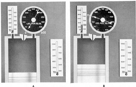
1B5. Relationship of pressure, temperature,
and volume. Figure 1-1A illustrates a simple
cylinder with a reciprocating piston. A dial pressure gage at the top of the cylinder registers
pressure inside the cylinder. Temperature inside the cylinder is recorded by a thermometer.
The thermometer at the side registers room
temperature. The piston is at outer dead center
in its stroke. At this stage, the pressure inside
5
Figure 1-1. Pressure, temperature, and volume relationship in a cylinder.
the cylinder is the same as atmospheric pressure
outside, and the dial of the pressure gage registers 0. Also, the temperature inside the cylinder is the same as room temperature, or approximately 70 degrees F.
In Figure 1-1B, force has been applied to
the piston, moving it about a third of the distance of its compression stroke. Air trapped in
the cylinder is compressed. As the volume of
this air is decreased, the pressure is increased
to about 155 psi. The temperature rises from
70 degrees F to about 300 degrees, indicating that heat has
been added to the air in the cylinder. This
shows that mechanical energy, in the form of
force supplied to the piston, has been transformed into heat energy in the compressed air.
In Figure 1-1C, more force has been applied to the piston, raising the pressure in the
cylinder to about 300 psi, and the temperature
to nearly 700 degrees F.
Figure 1-1D shows the final stage of the
compression stroke as the piston arrives at inner
dead center. Pressure is in the neighborhood of
470 psi and the temperature is about 1000 degrees F.
This illustration closely approximates the
conditions found in the compression stroke of a
modern submarine diesel engine. The temperature of the compressed air within the cylinder
has been raised to a sufficient degree to cause
automatic ignition on the injection of fuel oil
into the cylinder.
Thus, in summation, we see that during a
cycle of operation, volume is constantly changing due to piston travel. As the piston travels
toward the inner dead center during the compression stroke, the air in the cylinder is reduced in volume. Physically, this amounts to
reducing the space occupied by the molecules
of air. Thus, the pressure of the air working
against the piston crown and walls of the cylinder is increased and the temperature rises as
a result of the increased molecular activity. As
the piston nears inner dead center, the volume
is reduced rapidly and the temperature increases
to a point sufficient to support the automatic
ignition of any fuel injected.
Combustion changes the injected fuel to
gases. After combustion, the liberation of the
gases with a very slight increase in volume
causes a sharp increase in pressure and
6
Figure 1-1. Pressure, temperature, and volume relationship in a cylinder.
temperature. During the power stroke, volume increases rapidly, and toward the end of the
stroke, pressure and temperature decrease
rapidly.
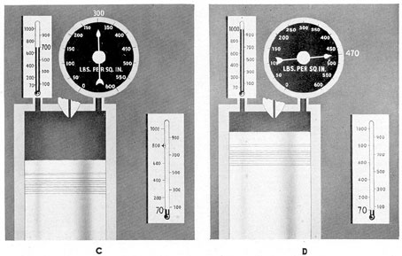
1B6. Pressure-volume diagrams. Various
methods and devices are used for measuring and
recording the pressures at various piston positions during a cycle of operation in an engine
cylinder. The result may be graphically illustrated by a diagram such as that shown in
Figure 1-2. Such diagrams are known as pressure-volume diagrams. In practice, they are
referred to as indicator cards.
Pressure-volume diagrams give the relationship between pressures and piston positions,
and may be used to measure the work done in
the cylinder. Also, if the speed of the engine
and the time involved in completing one cycle
are known, the indicated horsepower may be
computed by taking pressure-volume diagrams
on each cylinder and converting the foot-pounds
per unit of time into horsepower. This method
of determining horsepower, however, is not practicable on modern fleet type submarine engines.
1B7. Pressure-volume diagrams for the Otto
cycle, diesel cycle, and modified diesel cycle.
Figure 1-2 shows typical pressure-volume diagrams for the three types of engine cycles. Each
pressure-volume diagram is a graphic representation of cylinder pressure as related to cylinder
volume. In the diagrams the ordinate represents
pressure and the abscissa represents volume. In
actual practice, when an indicator card is taken
on an engine, the vertical plane is calibrated
in pressure units and the volume plane is calibrated in inches. The volume ordinate of the
diagram then shows the length of stroke of
the piston which is proportional to the volume.
Letters are located on each of the figures
in the diagrams. The distance between two adjacent letters on the figures is representative of
a phase of the cycle. Comparing the diagrams
provides a visible means of comparing the
variation in the phases between the three cycles.
1B8. The Otto cycle. The Otto cycle (Figure 1-2) is more commonly known as the
constant volume cycle and its principles form
7
Figure 1-2. Pressure-volume diagrams.
the basis for all modern automobile gasoline
engine designs. In this cycle, combustion is
timed to occur theoretically just as the piston
arrives at top dead center. Ignition is accomplished by a spark, and, due to the volatility
of the fuel-air mixture, combustion practically
amounts to an explosion. Combustion is completed with virtually no piston travel and hence,
little, if any, change in volume of the gas in the
combustion chamber. This gives rise to the description constant-volume cycle. During combustion there is a quick rise of the temperature
in the cylinder, immediately followed by a pressure rise which performs the work during the
power stroke.
The Otto cycle may be defined as a cycle
in which combustion induced by spark ignition
theoretically occurs at constant volume.
1B9. The diesel cycle. In the true diesel cycle,
only air is compressed in the cylinder prior to
ignition. This normally produces a final compression pressure of about 500 psi. At such a pressure the temperature of the compressed air may
range from 900 degrees to 1050 degrees F. Since most fuel
oils will ignite automatically with sufficient air
at a temperature of about 480 degrees F, ignition occurs as soon as the fuel oil spray reaches the
hot air. This is called compression ignition.
This combustion process (or burning of
the fuel and compressed air) is a relatively slow
process compared with the quick, explosion
type combustion process of the Otto cycle. The
fuel spray penetrates the compressed air, some
of the fuel ignites, then the rest of the fuel
charge burns. In the true diesel cycle, the expansion of gases keeps pace with the change in
volume occasioned by piston travel during the
combustion phase. Thus combustion is said to
occur at constant pressure.
The diesel cycle may be defined as a cycle
in which combustion induced by compression
ignition theoretically occurs at a constant
pressure.
1B10. Modified diesel cycle. We have previously described the Otto cycle as one in which
combustion occurs theoretically at constant volume, and the diesel cycle as one in which
8
combustion occurs theoretically at constant
pressure. In actual operation, a gasoline engine
does not follow the true Otto cycle, nor does
the diesel engine follow the true diesel cycle.
In fact, the operation of a medium- or high-speed diesel engine follows the modified diesel
cycle (Figure 1-2). This cycle involves phases
of both the Otto cycle and the diesel cycle in
that the combustion phase takes place at both
constant volume and constant pressure.
The modified diesel cycle, as applied to
diesel engines, may be defined as a cycle of
operation in which the combustion phase, induced by compression ignition, begins on a constant-volume basis and ends on a constant
pressure basis.
All submarine main and auxiliary engines
used today employ the modified diesel cycle.
The fundamental differences between the Otto
and the modified diesel cycles are:
1. The methods of mixing fuel and air.
This is accomplished before and during compression in the Otto cycle and usually near the
end of the compression phase in the modified
diesel cycle.
2. The methods of ignition. Spark ignition
is used in the Otto cycle and compression ignition is used in the modified diesel cycle.
The term diesel cycle has become popularly associated with all compression-ignition or
diesel engines. In actual practice, this is a misnomer when applied to modern, medium-speed
or high-speed diesel engines, because practically
all diesel or compression-ignition engines in this
category operate on the modified diesel cycle.
1B11. Thermodynamics of the Otto cycle,
every diesel cycle, and modified diesel cycle. In
every thermodynamic cycle there must be a
working substance. With internal combustion
engines, some form of substance must undergo
a change in the cylinder in order to convert heat
energy into mechanical energy. The working
substance in the cylinder of a compression-ignition engine is fuel oil.
After the fuel is injected into the cylinder,
combustion converts it into gases. This conversion is a thermodynamic change. A thermodynamic change during which the temperature
remains constant is called an isothermal process.
A thermodynamic change during which the temperature may vary but during which heat is
neither received nor rejected is called an adiabatic process.
In a strict sense the thermodynamic cycles
outlined below are not true thermodynamic
cycles. In a true cycle the process is reversible.
The working substance is heated, does work, is
cooled, and is heated again. In the cycle of an
actual engine, the residue of the combustion
process is exhausted at the end of the expansion
stroke and a new charge is taken into the cylinder for the next cycle of events. However, the
true thermodynamic cycle is useful for studying
the thermodynamic processes in actual engine
operation.
a. The Otto cycle. This is the thermodynamic cycle used as a basis for the operation
of all modern gasoline engines. The cycle
(Figure 1-2) consists of the adiabatic compression of the charge in the cylinder along the
line AB, the constant-volume combustion and
heating of the charge from B to C, the adiabatic
expansion of the gases from C to D, and the
constant-volume rejection of gases from the
cylinder along DA.
b. The diesel cycle. In the original diesel
cycle proposed by Dr. Diesel, the combustion
phase of the thermodynamic cycle was to be a
constant-temperature or isothermal process.
However, no engine was ever operated on this
cycle. As a result of his experimentation, however, a constant-pressure thermodynamic cycle
was developed. All early type, slow-speed diesel
engines approximated this cycle, although it is
in little use today.
In this cycle (Figure 1-2), adiabatic compression occurred along AB, to provide the temperature necessary for the ignition of the fuel.
Fuel injection and combustion were so controlled as to give constant-pressure combustion
9
along BC. This was followed by adiabatic expansion from C to D. Rejection of the gases
from the cylinder was constant volume from
D to A.
c. The modified diesel cycle. This is the
cycle (Figure 1-2) used in all fleet type submarine diesel engines and in practically all
modern diesel engines. In this thermodynamic
cycle, compression is adiabatic from A to B.
Combustion is partly constant volume from B
to C and partly constant pressure from C to D.
Expansion is adiabatic from D to E. Rejection
of gases from the cylinder is constant volume
along EA.
1B12. Thermal efficiency. The thermal efficiency of an internal combustion engine may be
considered the percentage of efficiency, in converting the total potential heat energy available
in the fuel into mechanical energy. We have
already stated that the mechanical equivalent of
heat energy is 778 foot-pounds for one Btu of
heat. By this equation, it is a simple matter
to figure how much work should be delivered
on an ideal basis from a given quantity of fuel.
An engine operating on this- basis would be 100
percent efficient. No internal combustion engine,
however, is 100 percent efficient, because heat
losses, conducted through the cooling and exhaust systems, and friction losses make the
thermal efficiency of any internal combustion
engine relatively low.
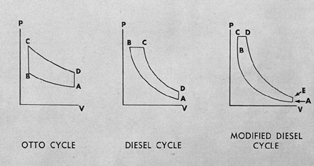
1B13. The 4-stroke diesel cycle. In the
4-stroke diesel cycle, the piston makes four
strokes to complete the cycle. There is one
power stroke or power impulse for every four
piston strokes, or two complete revolutions of
the crankshaft.
Figure 1-3 shows the four strokes and the
sequence of events that occur in the 4-stroke
diesel cycle.
1. The intake valve opens and a supply of
fresh air is drawn into the cylinder while the
piston makes a downward stroke.
2. With the intake valve closed, the piston
makes an upward stroke, compressing the air.
Pressure is generally around 500 psi with resultant temperatures as high as 900 degrees to 1050 degrees F,
depending on the design of the engine. At about
the end of this stroke, the fuel is injected into
the hot compressed air, and ignition and combustion occur over a relatively short period of
piston travel.
3. The expansion of combustion gases
forces the piston downward through one stroke.
This is called the power stroke. As the piston
nears the end of this stroke, the exhaust valve
opens, permitting some of the burned gases to
escape.
4. The piston makes another upward
stroke in which the remaining exhaust gases are
forced out of the cylinder. This completes the
cycle.
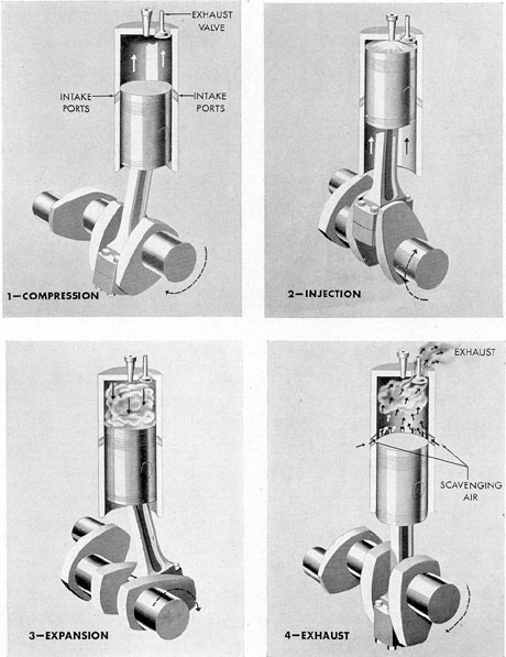
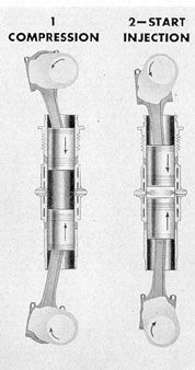
1B14. The 2-stroke diesel cycle. In this
cycle (Figure 1-4) the piston makes two strokes
to complete the cycle. There is one power stroke
for every two piston strokes or for each revolution of the crankshaft. An engine employing
this cycle requires a scavenging air blower to
assist in clearing the exhaust gases from the
cylinder, to replenish the cylinder with the necessary volume of fresh air, and to make possible
a slight supercharging effect.
Figure, 1-4 shows the two strokes and the
sequence of events that occur in the 2-stroke
diesel cycle as follows:
1. Start of compression. The piston has
just passed bottom dead center, the cylinder is
charged with fresh air, and both the intake ports
and the exhaust valve are closed. The fresh air
is trapped and compressed in the cylinder.
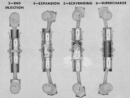
2. Injection. At about the end of the compression stroke, the fuel is injected and combustion occurs.
3. Expansion. Expansion of gases from
combustion forces the piston downward through
one stroke. As the piston nears the end of this
stroke, the exhaust valve is opened slightly in
10
advance of the uncovering of the intake ports.
This permits some of the burned gases to escape.
4. Exhaust. As the intake ports are
uncovered, the scavenging air which is under pressure,
rushes into the cylinder. This drives out the
remaining exhaust gases and completes the
cycle.
C. DIESEL ENGINE TYPES
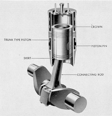
1C1. Single-acting diesel engine. Both the
4-stroke and the 2-stroke cycle diesel engines
illustrated and described in the previous section
were of the single-acting type (Figure 1-5). In
all single-acting engines the pistons used are
usually of the trunk type, that is, pistons whose
length is greater than their diameter. One end
of the trunk type piston is closed; this end is
called the crown. The opposite or skirt end of
the piston is open. The connecting rod extends
through the open end of the piston and is attached to the piston by means of the piston pin.
The term single-acting is used to describe
these engines because the pressure of the gases
of combustion acts only on one side (the crown)
of the pistons. In the 4-stroke cycle, single-acting engines, the power stroke occurs only once
in every two revolutions of the crankshaft. In
the 2-stroke cycle, single-acting engines, the
power stroke occurs once in every revolution of
the crankshaft. All of the main and auxiliary
diesel engines currently installed in fleet type
submarines are of the single-acting type.
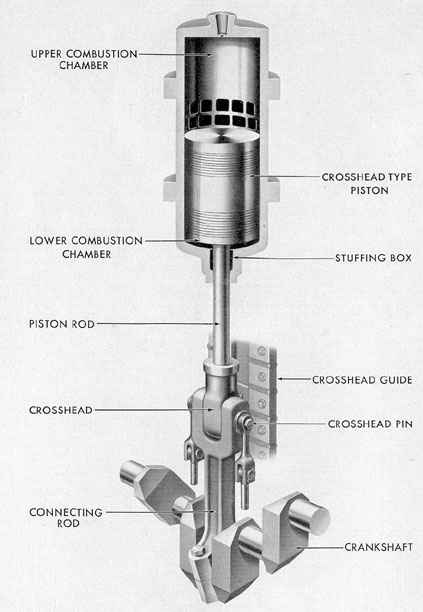
1C2. Double-acting diesel engine. A considerable number of double-acting diesel engines
(Figure 1-6), namely the HOR and MAN
engines, were used in installations for fleet type
submarines until recent years. Lately, however,
most of these double-acting engines have been
removed and replaced with 2-stroke cycle, single-acting engines. While double-acting engines
have no place in current installations, it is well
for the student to be familiar with their general
design and operation.
In double-acting diesel engines, the piston
proper is usually shorter and is described as the
crosshead type. The piston is closed at both
ends and has a rigid piston rod extending from
the lower end. Both ends of the cylinder are
closed to form a combustion chamber at each
end of the piston. The piston rod extends
through the cylinder head of the lower combustion chamber and passes through a stuffing box
to prevent leakage of pressure. The piston rod
is attached to a crosshead, and the connecting
rod is attached to the crosshead so that it may
turn freely on the crosshead pin. The crosshead
has a flat bearing surface that moves up and
down on a crosshead guide to steady the piston
rod and piston and prevent uneven wear.
Combustion occurs in the upper combustion chamber, and the pressure of the gases of
combustion is applied to the top end of the
piston during the downward stroke. At the completion of this stroke, combustion occurs in the
bottom combustion chamber and expansion
pressure is applied to the bottom end of the
piston during the upward stroke. The downward
power stroke serves as the compression stroke
for the lower combustion chamber and the upward power stroke serves as the compression
stroke for the top combustion chamber. Thus
the power strokes are double that of a single
acting engine and the engine is referred to as
a double-acting type.
The 2-stroke cycle, double-acting engine
has a distinct advantage in power output compared with the single-acting type. With twice
as many power strokes as a comparable single
acting engine and, with other conditions being
equal, it develops practically twice as much
power per cylinder. In addition, the operation
is smoother due to the fact that the expansion
stroke in one combustion chamber of the cylinder is balanced or cushioned by the compression
stroke in the opposite combustion chamber.
There are two principal difficulties encountered in adapting double-acting engines to submarine use. First, the crosshead type of piston
construction requires considerably more length
than that of single-acting engine types. As a
11
Figure 1-3. The 4-stroke diesel cycle.
12
Figure 1-4. The 2-stroke diesel cycle.
13
Figure 1-5. Single-acting diesel principle.
consequence, the engines must be built too high
and bulky for practical use in the confined
spaces available aboard submarines. Secondly,
many difficulties are encountered in effecting a
tight seal where the piston rod passes through
the stuffing box.
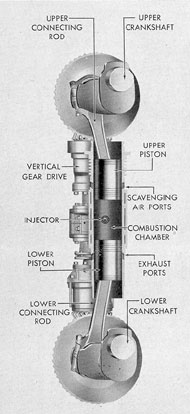
1C3. Opposed piston engine. The opposed
piston engine (Figure 1-7) is designed with
two pistons in each cylinder. The pistons are
arranged in opposed positions in the cylinder.
Piston action is so timed that at one point of
travel the two pistons come into close proximity
to each other near the, center of the cylinder.
As the pistons travel together they compress
air between them. The space between the two
pistons thus becomes the combustion chamber.
The point at which the two pistons come into
closest proximity is called combustion dead
center. Just prior to combustion dead center,
fuel is injected and the resultant expansion
caused by combustion drives the pistons apart.
The scavenging air ports are located in the
cylinder walls at the top of the cylinder and
are opened and closed by the movement of the
upper piston. The exhaust ports are located
near the bottom of the cylinder and are opened
and closed by the movement of the lower piston.
14
Figure 1-6. Double-acting diesel principle.
15
Figure 1-7. Opposed piston principle.
All the upper pistons are connected by
connecting rods to the upper crankshaft. All
the lower pistons are connected by connecting
rods to the lower crankshaft. In Fairbanks
Morse, opposed piston, submarine engines, the
upper and lower crankshafts are connected by
a vertical gear drive. The power from the upper
crankshaft not used to drive auxiliaries is transmitted through this drive to the lower crankshaft and ultimately to the engine final drive.
Figure 1-8 shows the various phases in a
2-stroke cycle of operation in an opposed piston
engine.
1. Both pistons are on the return travel
from outer dead center, the upper piston has
covered the scavenging air ports, the lower
piston has covered the exhaust ports, and compression has begun.
2. Just as both pistons approach combustion dead center, fuel is injected.
3. Injection has been completed, expansion
has begun, and both pistons are moving toward
outer dead center.
4. Expansion of gases from combustion
drives the pistons apart, causing the crankshafts
to turn. This is the power stroke of the cycle.
5. As the pistons approach outer dead center, the lower piston uncovers the exhaust ports
and most of the expanded gases escape. Just
before reaching outer dead center, the upper
piston uncovers the scavenging air ports and
scavenging air rushes into the cylinder, cleaning
out the remaining exhaust gases.
Figure 1-8. Opposed piston cycle.
16
6. The lower piston has covered the exhaust ports and scavenging air supercharges the
cylinder until the upper piston covers the scavenging air ports.
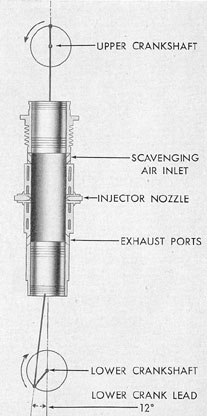
Figure 1-13 shows how the lower crankshaft leads the upper crankshaft by 12 degrees
in the Fairbanks-Morse submarine diesel engine. This lower crankshaft lead has a definite
effect both upon scavenging and power output.
Since the lower crankshaft leads the upper,
the exhaust ports at the lower end of the cylinder are covered slightly before upper piston
travel covers the intake ports. Thus, for a brief
interval, the exhaust ports are closed while the
intake parts are open. By the time the intake
port is covered, the cylinder has been charged
with fresh air well above atmospheric pressure.
Thus, through the lower crankshaft lead and
scavenging action, a supercharging effect is
achieved in this engine.
With the 12-degree lower crankshaft lead,
the lower piston has advanced the crankshaft
through a 12-degree arc of travel in the expansion phase of the cycle by the time the upper
piston has reached inner dead center. This
causes the lower piston to receive, at full engine
load, the greater part of the expansion work,
with the result that about 70 percent of the total
power is delivered by the lower crankshaft.
For submarine use, the opposed piston engine has three distinct advantages.
1. It has higher thermal efficiency than engines of comparable ratings.
2. It eliminates the necessity of cylinder
heads and intricate valve mechanisms with their
cooling and lubricating problems.
3. There are fewer moving parts.
Figure 1-8. Opposed piston cycle.
17
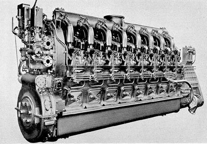
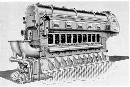
Figure 1-9. GM 16-278A, outboard side, control end, right-hand engine.
1C4. Modern fleet type submarine diesel engines. Modern diesel engines currently used
in fleet type submarine installations vary in
design but all are of the 2-stroke cycle type.
Following is a list of engines normally found on
fleet type submarines:
a. Main engines.
1. General Motors V-16 type. There are
two engine designs in this category, the 16-278A
and 16-248. Each engine has two banks of 8
cylinders, each arranged in a V-design with 40
degrees between banks. Each engine is rated at
1600 bhp at 750 rpm. Both engines are equipped
with mechanical or solid type injection and have
a uniflow valve and port system of scavenging.
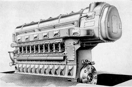
2. Fairbanks-Morse opposed piston type,
Model 38D 8 1/8. This model number includes
two engines, one a 10-cylinder and the other a
9-cylinder engine. Both engines are rated at
1600 bhp at 720 rpm. Both engines are
equipped with mechanical or solid type injection and have a uniflow port system of scavenging.
b. Auxiliary engines.
1. General Motors, Model 8-268. This engine is an 8-cylinder, in-line type. When operated in a generator set at 1200 rpm, it has a
power output of 300 kilowatts. This engine is
equipped with mechanical or solid type injection
and has a uniflow valve and port system of scavenging.
2. Fairbanks-Morse opposed piston type,
Model 38E 5 1/4. This is a 7-cylinder, opposed
piston type engine. When operated in a generator set at 1200 rpm, it has a power output of
300 kilowatts. This engine is equipped with
mechanical or solid type injection and has a
uniflow port system of scavenging.
D. SUBMARINE DIESEL ENGINE INSTALLATIONS
1D1. Submarine diesel engine installations.Figure 1-14 shows a typical main and auxiliary
engine installation aboard a modern, diesel-electric drive, fleet type submarine. Each engine is
coupled with a generator to form a generator
set. Through the main control cubicle, the current supplied by main generator sets may be
directed to charging the batteries or powering
the main motors. The auxiliary generator set
may be used directly either to charge the batteries or to power the auxiliary equipment. It
may also be used indirectly for powering the
main motors. Main motors are used for propulsion and may be powered either by the batteries or by the main generator sets.