| 1 |
| DEVELOPMENT OF THE SUBMARINE |
| |
| A. EARLY UNDERWATER DEVICES |
| |
|
1A1. Early Greek devices. The submarine first became a major factor
in naval warfare during World War I, when Germany demonstrated its full
potentialities. However, its advent at that time, marked by wholesale sinkings of
Allied shipping, was in reality the culmination of a long process of development.
Ancient history includes occasional records of attempts at underwater operations in
warfare. The Athenians are said to have used divers to clear the entrance of the
harbor of Syracuse during the siege of that city; during his operations against Tyre,
Alexander the Great ordered divers to impede or destroy any submarine defenses
the city might undertake to build. But in none of these records is there a direct
reference to the use of submersible apparatus of any kind. There is, however, a
legend that Alexander the Great himself made a descent into the sea in a device
which kept its occupants dry and admitted light.
In the Middle Ages, the Arabian historian Boha-Eddin reports that a diver using
submersible apparatus succeeded in gaining entrance into Ptolemais (Acre) during
the siege of that city in A.D. 1150. And in 1538, a diving bell was built and tested
at Toledo, Spain. Although it attracted the attention of the Emperor Charles V, the
device was never further developed and passed quickly into oblivion.
1A2. Bourne's idea. Not until 1580 does any record appear of a craft
designed to be navigated under water. In that year, William Bourne, a British naval
officer, made designs of a completely enclosed boat which could be submerged and
rowed under the surface. The device consisted of a wooden framework covered
with waterproofed leather. It was to be submerged by reducing its volume as a
result of contracting the sides through the use of hand vises. Although Bourne never
built this boat, a similar construction
|
|
sponsored by one Magnus Pegelius was launched in 1605. But the designers made
one serious oversight. They failed to consider the tenacity of underwater mud, and
the craft was buried at the bottom of a river during initial underwater trials.
1A3. Van Drebel's submersible. It is to Cornelius Van Drebel, a Dutch
physician, that credit is usually given for building the first submarine. To him is
conceded the honor of successfully maneuvering his craft, during repeated trials in
the Thames River, at depths of 12 and 15 feet beneath the surface.
Van Drebel's craft resembled those of Bourne and Pegelius in that its outer hull
consisted of greased leather over a wooden framework. Oars, extending through the
sides and sealed with tight-fitting leather flaps, provided propulsion either on the
surface or when submerged. Van Drebel built his first boat in 1620 and followed it
later with two others both larger but embodying the same principles. It is reported
that after repeated tests, James I took a trip in one of the larger models and
demonstrated its safety. But despite this evidence of royal favor, the craft failed to
arouse the interest of the navy in an age when all conception of the possibilities of
submarine warfare was still far in the future.
1A4. Eighteenth century plans. Submarine boats seem to have been
numerous in the early years of the 18th century. By 1727 no fewer than 14 types
had been patented in England alone.
An unidentified inventor whose work is described in the Gentleman's Magazine for 1747 introduced an ingenious device for submerging and surfacing his
submarine. His craft was to have had a number of goatskins built into the hull, each
of which was to be connected to an aperture in the bottom. He planned to submerge
the vessel by filling the skins with water, and to bring it to the
|
| |
1
|
|
surface again by forcing the water out of the skins with a "twisting rod." This seems to
have been the first approach to the modern ballast tank.
By that time, ideas were plentiful, some of them fanciful and grotesque, but some
containing elements capable of practical
|
|
application. Lack of full understanding of the physical and mechanical principles
involved, coupled with the well-nigh universal conviction that underwater navigation
was impossible and of no practical value, postponed for more than another hundred
years the attempt to utilize a submarine in warfare.
|
| |
| B. EARLY SUBMARINES |
| |
|
1B1. David Bushnell's Turtle. During the American Revolutionary
War, a submarine was first used as an offensive weapon in naval warfare. The
Turtle, a one-man submersible invented by David Bushnell and hand-operated
by a screw propeller, attempted to sink a British man-of-war in New York Harbor.
The plan was to attach a charge of gunpowder to the ship's bottom |
|
with screws and explode it with a time fuse. After repeated failures to
force the screws through the copper sheathing on the hull of the HMS Eagle, the submarine gave up, released the charge, and withdrew. The powder
exploded without result, except that the Eagle at once decided to shift to a
berth farther out to sea.
|
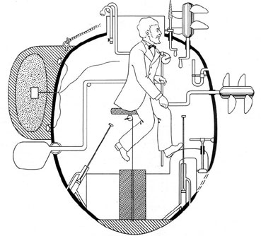
Figure 1-1. The TURTLE of David Bushnell, from a drawing by Lt. F. M. Barber,
USN, 1875.
|
| |
3
|
|
1B2. Fulton's Nautilus. Although his name is most often
associated with the invention of the steamboat, Robert Fulton experimented with
submarines at least a decade before he sailed the Clermont up the Hudson.
His Nautilus was built of steel in the shape of an elongated oval, and was
somewhat similar in structure to today's submarine. A sail was employed for
surface propulsion and a hand-driven propeller drove the boat
|
|
development of the craft, even though his model displayed some of the best features
of any submarine up to that time.
1B3, The Confederate "Davids". Development of the submarine boat
was held back during all of this period by lack of any adequate means of propulsion.
Nevertheless, inventors continued resolutely with
|
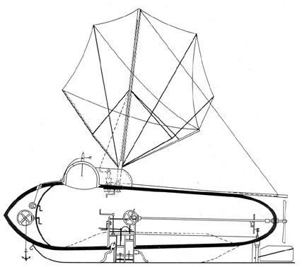
Figure 1-2. Fulton's NAUTILUS, about 1800 |
|
when submerged. A modified form of conning tower was equipped with a porthole
for observation, since the periscope had not yet been invented. In 1801, Fulton tried
to interest France, Britain, and America in his idea, but no nation ventured to
sponsor the
|
|
experiments upon small, hand-propelled submersibles carrying a crew of not more than six
or eight men. On 17 February 1864, a Confederate vessel of this type sank a
Federal corvette that was blocking Charleston harbor. This first recorded instance
of a
|
| |
3
|
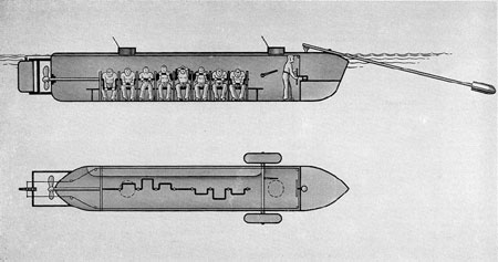
Figure 1-3. The HUNTLEY, one of numerous "Davids" constructed during the War
Between the States.
|
|
submarine sinking a warship was accomplished by a torpedo suspended ahead of the
bow of the Huntley as she rammed the Housatonic.
1B4. Garrett's steam propulsion. Interest in the improvement of the
submarine was active during the period of the War Between the States, but the
problem of a suitable means of propulsion continued to limit progress. Steam was
tried and finally in 1880 an English clergyman, the Rev. Mr. Garrett, successfully
operated a submarine with steam from a coal-fired boiler which featured a
retractable smokestack. During the same period, a Swedish gun designer,
Nordenfelt, also constructed a submarine using steam and driven by twin screws.
His craft, which
|
|
could submerge to a depth of 50 feet, was fitted with one of the first practical
torpedo tubes.
1B5. Electric propulsion. Meanwhile, electric propulsion machinery
had proved its utility in many fields, and in 1886, an all-electric submarine was built
by two Englishmen, Campbell and Ash. Their boat was propelled at a surface speed
of 6 knots by two 50-horsepower electric motors operated from a 100-cell storage
battery. However, this craft suffered one major handicap; its batteries had to be
recharged and overhauled at such short intervals that its effective range never
exceeded 80 miles. |
| |
| C. MODERN SUBMARINES |
| |
|
1C1. Holland's Plunger, Antedating the efforts of Nordenfelt were
the experiments of J. P. Holland of New Jersey, who launched his first boat in 1875.
Although his early
|
|
models embodied features that were discontinued as development progressed, many
of his initial ideas, perfected in practice, are in use today. Outstanding in
importance was
|
| |
4
|
|
the principle of submergence by water ballast, and the use of horizontal rudders to
dive the boat. However, not until 1895, did Holland, in competition with
Nordenfelt, finally receive an order for a submarine from the United States
Government. The vessel was propelled by steam on the surface and by electricity
when submerged. This craft was named the Plunger. The original craft was
redesigned frequently during construction and finally abandoned altogether in favor
of a newer model already building in the Holland shipyard. This was Holland's
ninth submersible, but it was the first to be delivered to the United States
Government. It was delivered in 1900, and was the basic design of all British
submarines to follow.
1C2. Lake's Submarines. Simon Lake, who began building submarines
in 1894, designed them primarily with peacetime uses in mind.
|
|
His vessels could travel about on the sea bottom, and had an air lock which
permitted a passenger in a diving helmet to emerge from the hull to walk about and
explore. In fact, Lake used his vessels extensively in commercial salvaging
operations. His first model, the Argonaut, Jr. was solely an experimental
one. It was built of two layers of yellow pine with a sheet of canvas between them,
and was operated by hand.
It was followed in 1897 by the Argonaut, a cigar-shaped hull 36 feet long
and powered by a 30-horsepower gasoline engine. This craft could submerge to the
bottom of a lake or river and roll along at bottom on three wheels; or, for navigating.
The wheels could be raised and carried in pockets in the keel. In 1898 the
Argonaut traveled under its own power through heavy November storms from
Norfolk to New York, and was thus the first
|
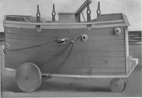
Figure 1-4. The ARGONAUT JR.
|
| |
5
|
|
submarine to navigate extensively in the open sea. In 1906 Lake built the
Protector and sold it to Russia. After it had successfully passed various severe
tests there, Lake built a number of submersibles on contract for the Russian
Government.
1C3. Conclusion. Thus the fundamental principles of construction and operation of submarine boats had been determined and demonstrated before the outbreak of World War I. By that time, too, internal combustion engines, both gasoline and Diesel, were available for use as practical power plants.
|
|
The invention of the periscope had materially increased the practical feasibility of underwater navigation. And the primary weapon of the submarine, the torpedo, had been perfected for use. Thus, the preliminary development of the submarine was finished, and the vessel was ready to take its place as a major factor in naval strategy. In place of the tiny, one-man contraptions that first dared to venture beneath the surface had come effective weapons, only a little short of the powerful, 70-man, fleet-type submarines that range the seas today.
|
| |
| D. GENERAL DATA
|
| |
|
1D1. Type of Construction. When the submarine rests on the surface, so little
of it is seen above the water that it has the appearance of being longer and more
slender than
|
|
it really is. Actually, the modern fleet type submarine is approximately 312 foot long with a superstructure deck tapering almost to a point, both fore and aft, from its greatest width of approximately 16 feet amidship.
|
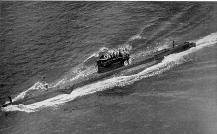
Figure 1-5. USS O-7 (1918)
|
| |
6
|
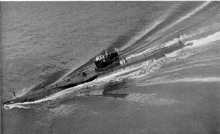
Figure 1-6. USS R-6 (1919).
|
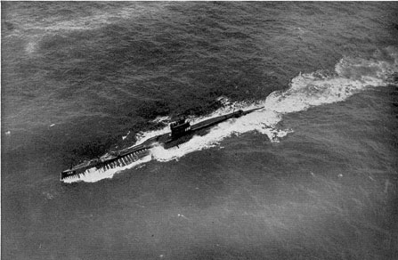
Figure 1-7. USS S-17 (1921)
|
| |
7
|
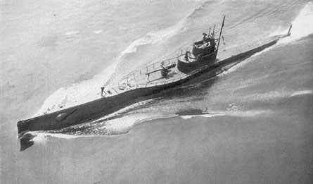
Figure 1-8. USS S-46 (1925).
|
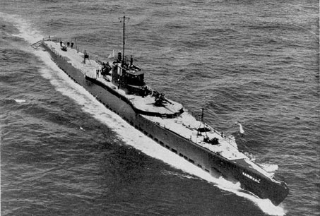
Figure 1-9. USS NARWHAL (1930).
|
| |
8
|
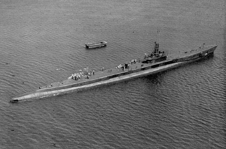
Figure 1-10. USS BLACKFIN (1944).
|
|
Beneath the superstructure deck is the all-welded hull; actually it is two hulls, for
the fleet-type submarine is a double-hull vessel. To understand the construction of a
submarine, one must first appreciate the conditions under which the vessel operates
below the surface. This means that the submarine must at all times be watertight,
otherwise self-destruction would result. The construction of the submarine,
therefore, is on the basis of the fabrication of a series of watertight containers into
one large watertight cylinder by means of watertight joints. However, since the
submarine must operate at times at great depths, these watertight containers must be
strong enough to withstand the pressure head of sea water at that depth. Therefore,
the watertight containers must be pressure vessels, that is, watertight
containers or cylinders capable of withstanding great
|
|
pressure. The fabrication of these containers into the hull of the vessel is illustrated in
Figure 1-11.
Pressure vessels, while capable of withstanding great pressure, do not in themselves
possess great rigidity. Being subject to mechanical action (leverage), they must be
secured to each other by one common strength member (the keel), as well as by
watertight connections (bulkheads). The submarine with its keel, pressure hull, and
watertight bulkheads is shown in Figure 1-12.
In the double-hull type of submarine, the pressure hull is inside the outer hull;
between the two hulls are the water and the fuel oil tanks. The double-hull
construction extends from the after bulkhead of the forward torpedo room to the
forward bulkhead of the after torpedo room. The pressure hull,
|
| |
9
|
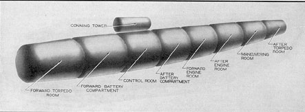
Figure 1-11. Type of construction, showing arrangement of compartments, without
the superstructure or tanks.
|
|
or inner hull, extends from the forward bulkhead of the forward trim tank to the
after bulkhead of the after trim tank. Above the hull is built a non-watertight
superstructure which forms the main deck, for use when surfaced.
A gun, usually a 5"/25, wet type, is mounted topside. The space below the deck is
used as locker space for stowing anchor gear, lines, and other gear that cannot be
damaged by water. Ready ammunition in boxes and the ship's boat are also kept
here.
|
|
The deck is perforated on either side with circular holes among the entire length to
prevent air pockets from forming within the superstructure when it becomes
flooded. A watertight tower, know as the conning tower, extends upward
through the superstructure amidships. The top of the conning tower is used as a
bridge when on the surface, but when submerged, the control of the boat is
maintained either from the conning tower or from a compartment directly below it,
known as the control room. Periscopes
|
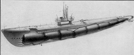
Figure 1-12. Type of construction, showing the general arrangement of the
superstructure.
|
| |
10
|
|
operated from the conning tower extend above the bridge and are used for making
observations when submerged.
1D2. Size. In the accompanying table are shown dimensional data of
the fleet type submarine.
1D3. Depth and pressure. The modern fleet
|
|
Individual compartments are air tested for tightness only to a pressure of 15 psi.
Watertight bulkheads are designed structurally and strengthened through
reinforcements to withstand the pressure at the previously mentioned test depths.
The total pressure that the hull must
|
| |
| Displacement (designed) | 1,523 tons |
| Displacement (surface) | 1,816 tons (diving trim |
| Length (over-all) | 311'-9" |
| Breadth (extreme) | 27"-4" |
| Mean draft (surface) | 15'-3" (diving trim) |
| Number of frames | 139 |
| Frame spacing (except 35 to 62 and 69 to 105 spacing 30") | 24" center to center |
| Freeboard at stern | 3'-11" |
| Freeboard at bow | 12'-5" |
| Diameter pressure hull (max.) | 16'-0 3/8" |
| Distance from keel to centerline of hull | 12'-0" |
| Floodable space | |
| Forward torpedo room | 4,481 cu. ft. |
| Forward battery compartment | 4,056 cu. ft. |
| Control room | 4,653 cu. ft. |
| Conning tower | 760 cu. ft. |
| After battery compartment | 5,821 cu. ft. |
| Forward engine room | 4,535 cu. ft. |
| After engine room | 4,277 cu. ft. |
| Maneuvering room | 3,410 cu. ft. |
| After torpedo room | 3,455 cu. ft. |
| | |
| Total floodable space | 35,448 cu. ft. |
|
|
type submarine is built to withstand the pressure of a head of sea water, consistent
with requirements as shown by battle experience and with the Bureau of Ships
specifications. The pressure is measured in actual submergence tests from the
surface of the water to the axis of the vessel through its pressure hull.
|
|
withstand is actually the differential pressure between the interior hull pressure and
the external head of water at a given depth.
1D4. Main propulsion, speed and cruising radius. The average fleet type
submarine is driven by four main propulsion diesel engines, each capable of
producing 1600 hp.
|
| |
11
|
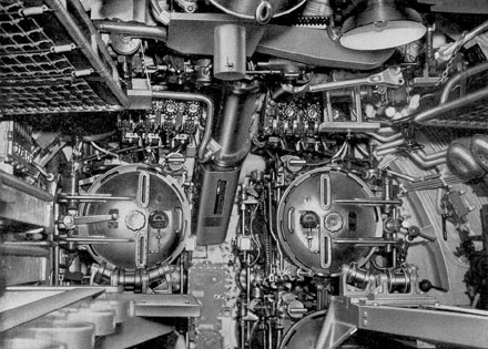
Figure 1-13. Torpedo tubes.
|
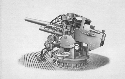
Figure 1-14. Deck gun, 5"/25.
|
| |
12
|
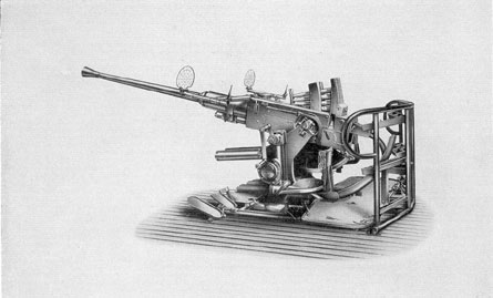
Figure 1-15. Anti-aircraft gun, 40 mm.
|
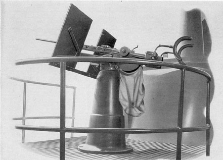
Figure 1-16. Anti-aircraft gun, 20 mm.
|
| |
13
|
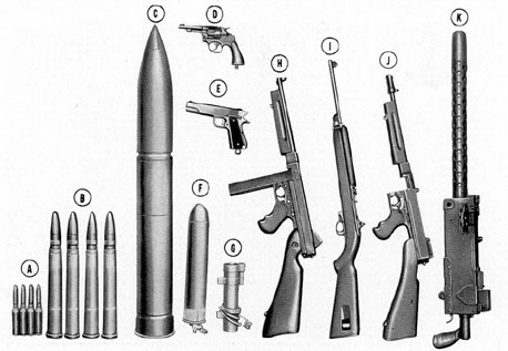
Figure 1-17. Small arms and pyrotechnics.
|
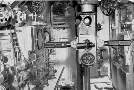
Figure 1-18. Conning tower, looking aft.
|
| |
14
|
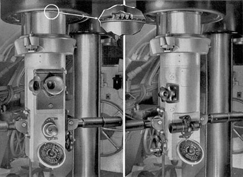
Figure 1-19. Lower portion of a modern periscope.
|
| |
15
|
|
The four main generators each produce 1100 kw. There are four main motors,
driven by the generators or batteries, each producing about 1375 hp. The two
reduction gears are of the herringbone, 2-pinion type and produce about 2750 hp at
each shaft. The auxiliary engine is rated at 450 hp and drives a 300-kw generator.
The average fleet type submarine is capable of a speed of about 21 knots when
operating on the surface and approximately 10 knots when submerged. This
submarine has a cruising range in excess of 12,000 miles.
1D5. Ship's complement and ship's armament. a. Ship's
complement. The personnel aboard the fleet type submarine range in number
from 66 to 78. Officers number from 6 to 8, and men from 60 to 70.
b. Ship's armament. Torpedo tubes (figure 1-13) are the main
offensive and defensive armament of the submarine. A total of 10 21-in. tubes are
carried, six forward and four aft. Those shown in the illustration are No. 1 and No.
2. Located in pairs below tubes No. 1 and No. 2 are Nos. 3 and 4, and Nos. 5 and
6. The upper half of the No. 3 tube is visible in the lower right corner of the
illustration.
Immediately above tubes No. 1 and No. 2 is the torpedo tube blow and vent
manifold used for blowing or venting the tubes, WRT tank, and the trim tank. (See
Figure 1-13.)
|
|
The rollers aft of the tubes and the racks farther aft (not shown in the illustration)
are used for torpedo reload. The tubes can be fired electrically or by hand when
surfaced or submerged. The condition of the tube is indicated by the torpedo ready
lights, shown to the left of the No. 2 tube.
The 5"/25 deck gun (Figure 1-14) is a dual purpose gun. It is so mounted
as to be used effectively against surface craft and aircraft. Two guns may be
carried: if one gun is carried it is located abaft of the conning tower.
The 40-mm anti-aircraft gun (Bofors), shown in Figure 1-15, is mounted
forward of the conning tower. It is principally an anti-aircraft weapon, but may be
used against surface craft. It is a rapid fire, recoil type of gun. In some instances it
is being replaced by a 37-mm gun. The 40-mm gun sometimes replaces two 20-mm
guns.
The 20-mm anti-aircraft gun (Figure 1-16), sometimes referred to as the
Oerlikon gun, is located either forward or aft of the conning tower on the
bridge deck. It is a rapid fire, recoil type of gun. In some instances the single
mount has been replaced by twin mounts. Four 20-mm guns are carried by the fleet
type submarine.
In addition to the armament described above, the fleet type submarine carries other
small arms and pyrotechnics (Figure 1-17). Chief among these are two 30-caliber
and four 50-caliber Browning machine guns, and one 45-caliber Thompson
submachine gun.
|
| |
16
|
