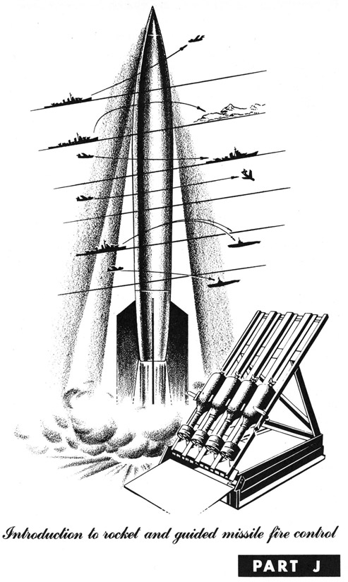
INTRODUCTION TO ROCKET AND GUIDED MISSILE FIRE CONTROL
The Navy's "Fantastic" Weapons
So far in your study of Fire Control Fundamentals you have considered only the Navy's standard, conventional weapons. You learned about main battery and antiaircraft guns which fire conventional projectiles. Then you saw how submarines are attacked using depth charges and ahead-thrown weapons-other conventional weapons. In the last section of these sheets you found out about the use of torpedoes-complex and subject to a high degree of control-but still conventional weapons. Now, however, in this section of sheets you will be introduced to the Navy's unconventional weapons-rockets and the really "fantastic" guided missiles.
You will find out, on the following sheets, what rockets and guided missiles are, and how the basic fire control problem is applied to the control of these weapons. You will see how rockets are used most effectively and how guided missiles are directed unerringly to their targets. You will get a quick look at one of the most fascinating aspects of fire control-the problem of rocket and guided missile control.
Rockets are by no means new weapons, having been used several centuries ago for military purposes. But the development of conventional guns caused rockets to be neglected until fairly recently, when effective means of control were developed. Guided missiles, however, are the latest weapons employed by the Navy, and they are still in the process of being developed to their fullest capabilities.
Now let's go on to learn something about this final specialized application of the basic fire control system.
J-2
INTRODUCTION TO ROCKET AND GUIDED MISSILE FIRE CONTROL
Rockets and Their Uses
Rockets are self-propelled missiles which can be launched from ships and planes against air, surface and underwater targets. Rockets are propelled by the high-velocity discharge of high-pressure gases from the rear of the missile. The gases are the result of the combustion of fuels carried by the rocket. The rearward discharge of these gases produces a forward thrust on the rocket, and thus propels it forward.
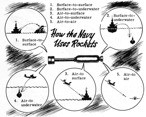
Projectiles fired from conventional guns follow a trajectory which can be accurately predicted; hence these weapons can be brought to bear effectively on specific targets at great ranges. The flight of a rocket, however, is not as stable as that of a conventional projectile for several reasons. As a result rockets are less accurate than conventional projectiles and are not used for pin-point fire against long-range targets. They are used primarily for the following types of fire:
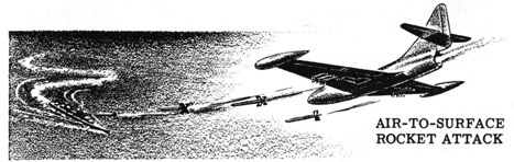
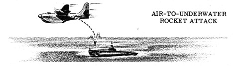
Surface-to-surface fire usually means saturation bombardment of enemy shore installations by rockets fired from ships. Surface-to-underwater rockets are one type of ahead-thrown missile used by surface ships in antisubmarine warfare. Air-to-surface rockets are fired by planes diving against enemy ships or shore installations. Air-to-underwater rockets are employed by planes against submerged submarines. Air-to-air rockets are fired by one plane at an enemy plane. You will learn more about each of these applications a little later.
J-3
INTRODUCTION TO ROCKET AND GUIDED MISSILE FIRE CONTROL
Guided Missiles and Their Uses
The rockets discussed on the preceding sheet follow a fixed course after being launched. They are aimed by positioning the launchers in elevation and train on surface ships, or by pointing the attacking plane at the target in the case of air-borne rockets. Their chief value is in saturation bombardment and short-range fire from planes which can get very close to the target.
Because rockets can be built which are capable of long range flight-200 miles and more-methods have been developed to improve the accuracy of the missiles at long ranges by providing means for controlling their flight after they are launched, thus utilizing their long-range capabilities. When rockets are so equipped with control devices they are called "guided missiles."
Various types of guided missiles have been developed for special purposes. Some are controlled from the launching ship, plane or shore installation. Others are of the homing type, in that they carry their own radar equipment and pursue the target guided by radar signals from the target itself. You will learn more about various guided missile control systems a little later.
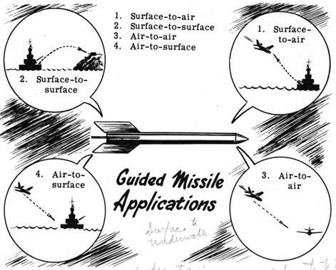
Among the missions assigned to guided missiles at the present time are the following types of attack:
J-4
INTRODUCTION TO ROCKET AND GUIDED MISSILE FIRE CONTROL
The Fire Control Problem Applied to Rockets and Guided Missiles
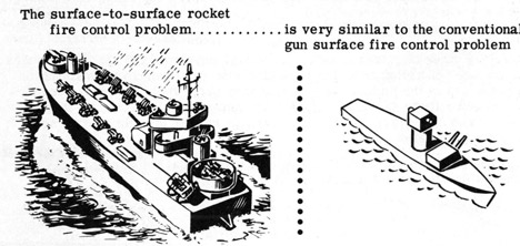
The fire control problem as it applies to the control of short-range rockets is very similar to the basic fire control problem with which you are already well acquainted. It involves, generally, the determination of present target position, correcting for own ship motion, stabilizing the fire control system and rocket launchers, and elevating and training the launchers to fire the rockets so that they land on the target. The actual solution of the problem varies considerably depending on how the rockets are being employed-surface-to-surface, air-to-surface, etc. On the next few sheets we will take a quick look at the various applications of rocket fire, but our subsequent discussions will be concerned primarily with the surface-to-surface problem.
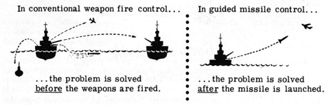
The guided missile control problem is the same as the basic fire control problem, except that the problem is solved after the missile has been launched and while it is traveling to the target. In surface, antiaircraft, torpedo, rocket and antisubmarine fire control systems the problem is solved before the weapons are fired. The problem of controlling guided missiles is not to determine the target's position in relation to the firing ship, but to determine its position in relation to the missile itself so that the missile's course can be adjusted to cause it to strike the target.
On the following sheets you will learn more about various types of rockets, their uses and a typical control system. Then you'll find out about various types of guided missiles and their control systems.
J-5
INTRODUCTION TO ROCKET AND GUIDED MISSILE FIRE CONTROL
Types of Rockets and Rocket Launchers
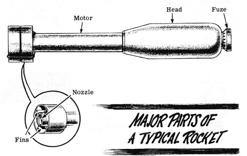
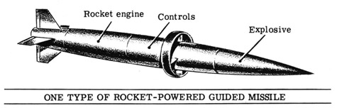
A large variety of specialized rockets have been and are being developed by the Navy, each designed to perform most effectively the particular job for which it is intended. However, all rockets, regardless of their size or intended use, consist of the following parts: (1) fuze, (2) head, (3) motor, (4) nozzle, and in most types (5) fins. These parts are shown below.
The fuze, like the fuze on conventional projectiles, detonates the rocket when it contacts a solid object. The head contains the explosive charge. The motor carries the rocket's fuel and includes a combustion chamber where the fuel is burned. The high-pressure gases resulting from combustion are discharged from the nozzle, thus producing the propelling force. The fins help to stabilize the rocket during its flight.
The rocket shown above is typical of the general-purpose barrage rockets fired from surface ships and used primarily to lay down barrages against enemy shore installations in the course of landing operations. Its head is 4.5 inches in diameter and its overall length is about 31 inches. The head carries a 6.5-pound charge of explosive. A variety of launchers have been developed for this rocket, ranging from comparatively small portable types to multi-rail launchers fastened permanently to the ship's deck and capable of firing 12 rockets within 3 or 4 seconds. The 4.5-inch rocket is fired by means of an electric firing circuit energized from the ship's power system or batteries. When the circuit is closed, connections from the launcher to the rocket actuate a firing mechanism within the motor to initiate combustion of the fuel and thus fire the rocket.
J-6
INTRODUCTION TO ROCKET AND GUIDED MISSILE FIRE CONTROL
Types of Rockets and Rocket Launchers (continued)
In addition to the 4.5-inch general-purpose rocket discussed on the previous sheet, the Navy also uses 3.5-inch, 5.0-inch, 7.2-inch and 11.75-inch rockets at the present time. Other experimental types are in various stages of development.
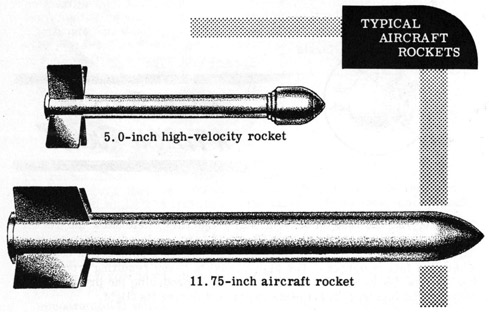
Various specialized aircraft rockets have been developed for use by aircraft against surface ships, submarines and land targets. These include the 3.5-inch and 5.0-inch aircraft rockets, the 5.0-inch high-velocity rocket, the 7.2-inch antisubmarine rocket, and the 11.75-inch aircraft rocket. The 5.0-inch high-velocity rocket attains a velocity of 1,375 feet per second in addition to the plane's speed, and will penetrate six feet of concrete; it can thus be used effectively against pillboxes, ships and tanks. The 11.75-inch aircraft rocket carries 150 pounds of TNT and has the explosive effect of a 500-pound bomb.- These two types are shown below.
Other types of aircraft rockets are under development, including an air-to-air rocket which is small enough to be carried in quantity, yet sufficiently powerful to destroy any plane with a direct hit. Aircraft rockets are carried in launchers mounted on the underside of the plane. Depending on the type of rocket it is designed to handle, a launcher may be forward-firing, rearward-firing (antisubmarine rockets) or drop type (for 11.75-inch rockets).
You read about ahead-thrown antisubmarine weapons in a previous section of these sheets. One such missile used by surface ships is the 7.2-inch rocket, which is very much like the 4.5-inch barrage rocket previously discussed.
J-7
INTRODUCTION TO ROCKET AND GUIDED MISSILE FIRE CONTROL
The Fire Control Problem Applied to Rockets
Before going into the details of a typical surface-to-surface rocket fire control system, as we will do starting on the next sheet, let's take a quick look at the various other short-range rocket uses and the fire control problem each involves.
In addition to firing barrage rockets against enemy shore installations or ships, some surface craft employ them as ahead-thrown weapons in antisubmarine warfare. The fire control problem involved and its solution for this type of attack were discussed in the section on antisubmarine fire control, and will not be discussed further here.
Aircraft using short-range rockets against enemy surface, underwater or air targets are not equipped with elaborate fire control systems to direct the launching of their rockets. Forward-firing rockets are used against surface and air targets. These weapons are given their initial direction toward the target by releasing them while the plane is diving at the target. The pilot heads for the target, leads it by employing a lead-computing sight, and launches the rockets when he is close enough to the target to be reasonably sure of scoring a hit. The sight compensates for the effect of gravity, plane's speed and range.
When planes employ rockets as antisubmarine weapons, a rearward-firing launcher is used. The plane so equipped utilizes a magnetic submarine-detection device which indicates when the plane is directly over a submarine. At this moment a rocket is fired rearward with sufficient velocity to counteract the plane's forward motion; the rocket thus follows a substantially vertical path to the target.
Now let's go on to find out about a surface-to-surface rocket fire control system and how it operates.
J-8
INTRODUCTION TO ROCKET AND GUIDED MISSILE FIRE CONTROL
A Typical Surface-to-Surface Rocket Fire Control System
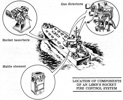
During World War II a number of LSM's were redesigned to provide for installation of rocket launcher assemblies, each capable of firing 30 rounds per minute. LSM's so equipped were designated as LSMR's, and mount 10 launcher assemblies, which may be operated in automatic fire by either of two duplicate rocket fire control systems. Each system includes a gun director, a stable element, a gun-order corrector and various indicating, transmitting and receiving devices. The launchers and directors are located above decks as shown below. The stable elements, gun-order correctors and auxiliary instruments are located in protected positions below decks. Either of the rocket fire control systems may control any or all of the rocket mounts at the same time, and either system may be used to control the ship's single 5-inch gun. Although the various elements of the fire control systems were developed for the control of conventional guns, they have been successfully converted for the control of rocket launchers.
The rockets may be fired from controls in the combat information center, at either gun director or at each launcher. The mounts have firing stops to prevent firing into own ship's structures.
Now let's find out about the various methods of operation possible with the rocket fire control system, and how each component of the system functions during each type of operation.
J-09
INTRODUCTION TO ROCKET AND GUIDED MISSILE FIRE CONTROL
Operation of the Rocket Fire Control System
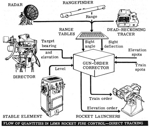
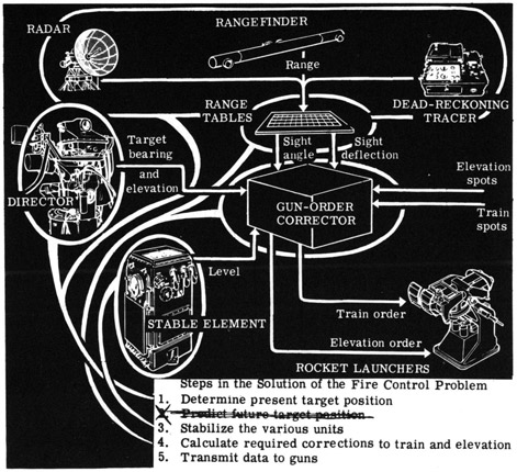
The rockets launched from LSMR's are primarily used for saturation bombardment of enemy shore installations, rather than for fire against enemy surface ships. Thus the target is ordinarily fixed, and correcting for target motion is unnecessary in the solution of the fire control problem. Sight angle and sight deflection are therefore dependent only on range, and are obtained-in all methods of operation-from a range table or by use of a ballistic slide rule. These values are then fed to the gun-order corrector, where they are combined with information on target bearing and elevation from the gun director, level from the stable element, and train and elevation spots from an observer. The gun-order corrector calculates required gun elevation and train orders and transmits them to the rocket launchers.
The illustration below shows how the system operates in direct tracking-the primary means of control. The variations in the flow of quantities and function of components in the other methods of operation will be detailed on the next sheet.
Note that range may be obtained from radar equipment, a rangefinder or a "dead-reckoning tracer." This device automatically maintains a continuous plot of the ship's position, with respect to the shore, from which range can be measured. Now let's find out about the variations present in other methods of operation.
J-10
INTRODUCTION TO ROCKET AND GUIDED MISSILE FIRE CONTROL
Operation of the Rocket Fire Control System (continued)
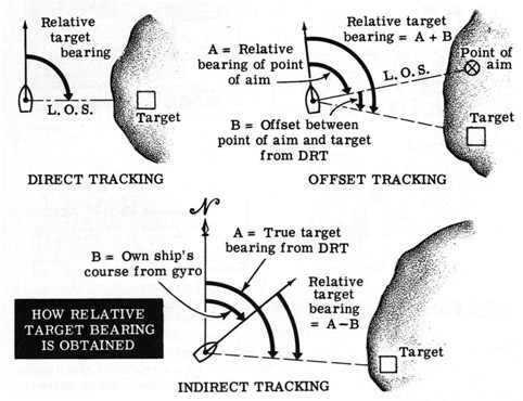
During direct tracking operation the director line-of-sight is kept on the target, thus measuring target bearing and elevation directly. This method of operation was explained and illustrated on the preceding sheet.
In offset tracking, a point of aim on shore is designated at some convenient fixed distance away from the target, and the director's line-of-sight is trained on the point of aim. Relative bearing of the point of aim is then measured by the director and transmitted to a train indicator. Offset between the point of aim and the target, obtained from the plot on the dead-reckoning tracer, is also sent to the train indicator, which then calculates relative target bearing and transmits it to the gun order corrector. This method of sighting on a point of aim other than the target is used when the target is obscured. Thus once the point of aim is established the firing ship need not keep the target in sight to maintain fire.
In indirect tracking, true target bearing, obtained from the plot on the dead-reckoning tracer, is combined with own ship's course obtained from the ship's gyro. The resultant relative target bearing is then fed to the gun-order corrector. In this method of operation the director is not used. Indirect tracking depends on the dead-reckoning tracer (DRT), as does offset tracking, to provide a picture of own ship's position with respect to the shore, and hence the target. Thus the target need not be within sight of the ship for effective fire.
J-11
INTRODUCTION TO ROCKET AND GUIDED MISSILE FIRE CONTROL
Operation of the Rocket Fire Control System (continued)
The steps in the solution of the rocket fire control problem are slightly different from the steps in the solution of the basic fire control problem. Since the target-enemy shore installations-is ordinarily fixed, no correction for target motion or prediction of future target position is required. Here is how the various components of the rocket fire control problem enter into the solution of the problem.
The radar equipment, rangefinder and/or dead-reckoning tracer, together with the gun director, determine the target's range and bearing and hence its present position, thus providing a solution to the first step in the problem. The stable element sends a continuous measure of level to the gun-order corrector. This corrects for the effects of deck motion and solves the third step by stabilizing the various units of the fire control system. The fourth step is solved by use of the range tables to determine sight angle and sight deflection, and using these values as inputs to the gun-order corrector, which then calculates the required gun elevation and train orders.
Now you've seen how an LSMR rocket fire control system controls the launching of short-range barrage rockets during surface-to-surface bombardment of enemy shore installations. This is the most common Navy application of surface-to-surface short-range rockets.
J-12
INTRODUCTION TO ROCKET AND GUIDED MISSILE FIRE CONTROL
Types of Guided Missiles
Guided missiles are the really fantastic weapons in the Navy's arsenal. Rapid advances have been made in this field in the past few years, and new developments are continuing right now. The potentialities of guided missiles in warfare are very great-imagine firing a missile at a ship or plane and never missing, regardless of how the target maneuvers to escape! This is just what happens when guided missiles are employed.
You already know that guided missiles are long-range missiles which are subject to some means of control capable of altering the missile's course as necessary to cause it to strike its designated target, regardless of the target's evasive maneuvers. You'll see a little later how control is effected-right now let's take a look at the various types of guided missiles.
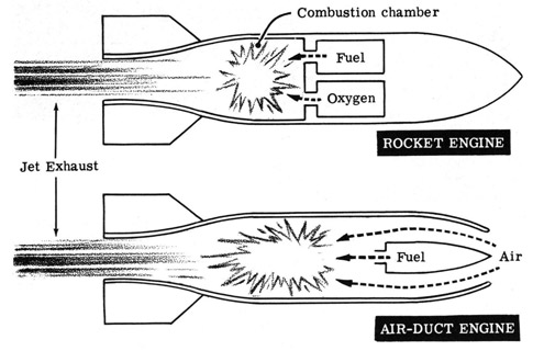
There are two classes of "jet" engines used as power plants for guided missiles: (1) the rocket type, and (2) the air-duct type. So far we have considered only the rocket type, which may use solid fuel for short ranges or liquid fuel for greater range. The principal difference between rocket and air-duct types of propulsion is that in the former the rocket carries the oxygen required for combustion of its fuel, whereas in the latter an air-duct scoops up air for combustion from the atmosphere. Thus a rocket can operate in a vacuum, but an air-duct engine can operate only where sufficient air can be scooped up by its air duct.
Both types of jet engines are used to power guided missiles-the air-duct type where great range is required, the rocket type where very high speed and acceleration are necessary to overtake rapidly moving targets.
J-13
INTRODUCTION TO ROCKET AND GUIDED MISSILE FIRE CONTROL
Types of Guided Missiles (continued)
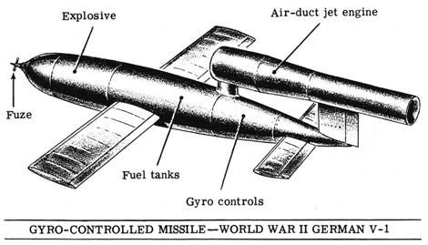
Some guided missiles are guided only to the extent of having a pre-set gyro system to keep them on course, and perhaps a pre-set power cut-off. The early guided missiles, using air-duct engines and exemplified by the German V-1 of World War II, were of this type. This method of control is suitable for long range area bombardment, but is not sufficiently accurate for effective long-range pin-point attacks, since no corrections can be applied to the missile's course after it is launched.
The three major classes of guided missiles in use today are: (1) homing, (2) beam-riding, and (3) commanded missiles. These are classifications based on the method employed to control the missile's course. You will learn more about these methods later. Suffice it to say now that homing guided missiles guide themselves to the target, while beam-riding and commanded missiles are guided to the target by exterior sources.
At the present time nearly all guided missiles are powered by rocket type jet engines, since this type offers much greater speed and acceleration than does the air-duct type.
J-14
INTRODUCTION TO ROCKET AND GUIDED MISSILE FIRE CONTROL
Guided Missile Launchers
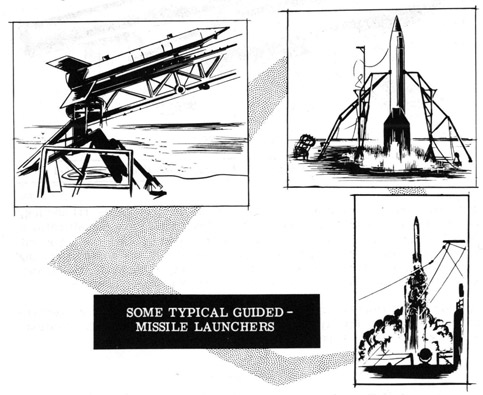
The first step in directing a guided missile against an enemy target is to launch it from the attacking ship or plane. Some means must be provided to support the missile and give it initial guidance as it starts on its journey. The requirements for a guided missile launcher are that it must be compact for shipboard or aircraft installation, it must provide stable and rigid support, and it must be rugged enough to withstand the initial blast of the missile. In some cases the launcher must be capable of being trained and elevated to start the missile in the desired initial direction.
Various types of launchers have been designed specifically to handle different types of guided missiles. Among the first was a pit launcher, which was simply a pit in the ground in which the missile rested on its stabilizing fins in a vertical position. Some other more recent typical launchers for firing' missiles from land and surface ships are shown below.
Among the first airborne guided-missile launchers to be used were gravity launchers, which were essentially modified bomb racks. This type of launcher simply released the missile, which then fell free of the plane and proceeded under its own power. Later airborne launchers incorporated rails which supported and guided the missile during the start of its flight.
J-15
INTRODUCTION TO ROCKET AND GUIDED MISSILE FIRE CONTROL
The Problem of Guided Missile Control
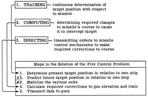
As you already know, guided missiles differ from conventional projectiles and barrage rockets in that the latter are committed to a given course at the instant of firing, while the former's course is altered during flight. Solution of the guided missile control problem, in order to achieve effective direction of the missile against a target, requires the continuous performance of three functions while the missile is in flight. These functions are: (1) tracking, (2) computing, and (3) directing.
Tracking involves continuous determination of the relative positions of missile and target. Computing means using the tracking data to determine how much and in what direction the missile's course must be altered to score a hit. Directing is the implementation of the computer results in the form of orders to the mechanisms which physically control the wings which in turn control movement of the missile. These three functions may be performed by guided missile fire control system components located entirely within the missile itself, or by equipment located at the control station on the launching ship or plane. You will see how these functions are performed by various specific guided missile control systems a little later.
A direct comparison can be made between the basic fire control problem solution and the three steps in effective missile guidance. This comparison is shown below, but you must bear in mind that the basic problem as exemplified in the control of conventional guns is solved continuously for a given set of conditions up until the time when the projectile is fired, whereas the solution of the guided missile problem commences when the missile is launched and continues until the missile strikes the target.
J-16
INTRODUCTION TO ROCKET AND GUIDED MISSILE FIRE CONTROL
The Problem of Guided Missile Control (continued)
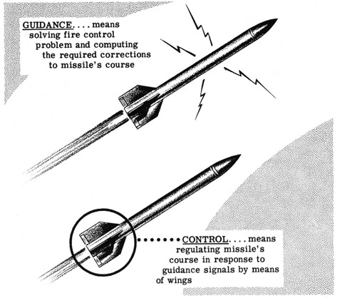
There are two phases to the problem of directing a guided missile against a target. These phases are the problem of guidance, and the problem of control. It may sound to you as if they are one and the same, but they are not. Guidance refers to the problem of solving the guided missile fire control problem-tracking, computing and directing. It involves the use of the radio, radar and computing equipment necessary to determine how a missile's course must be changed to cause it to intercept the target, and to get this information to the missile's control mechanisms. Control is concerned with the aerodynamic problem of regulating the missile's flight in the desired manner in response to guidance signals. Aerodynamic control is a study in itself, and will not be considered here. We are interested in the problem of guidance-the various methods employed and the equipment used with each method.
There are four principal systems of guidance: (1) pre-set gyro systems, (2) homing systems, (3) command systems and (4) beam-rider systems. On a previous sheet you were introduced to the various types of guided missiles and were told that one classification was the method of guidance employed. On the next few sheets each of these guidance systems will be discussed in detail.
J-17
INTRODUCTION TO ROCKET AND GUIDED MISSILE FIRE CONTROL
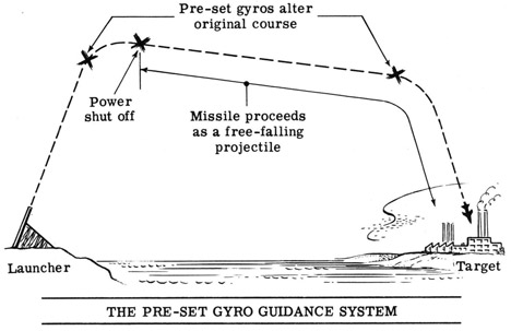
The Pre-set Gyro Guidance System
The earliest guided missiles used pre-set gyros to control their flight. The missile's control surfaces were manipulated by gyro-controlled devices. Before the missile was launched the gyros were set in such a way as to cause the missile to follow a set course. Gyros also provided automatic fuel cut-off when the missile attained a predetermined velocity sufficient to carry it on a free-flight path to the target.
Here is how the system operated. After the missile was launched, its gyros caused it to alter its original course and turn in the desired direction toward the target. A computer carried by the missile maintained a continuous record of progress, based upon angle of climb and acceleration during the upward flight of the missile. When the proper combination of velocity and direction was attained the power was shut off, and the missile proceeded as a free projectile to the target.
As previously mentioned, the Germans utilized this type of control in their V-1 and early models of V-2 missiles during World War II. The former employed an air-duct jet engine while the latter was a true rocket. Since there was no control from exterior sources after launching, accuracy was dependent upon the precision of initial gyro settings. Accuracy was about 4 percent of range, which was acceptable for area bombardment at ranges up to 200 miles-the purpose for which these weapons were designed.
Although not extensively used at present, the pre-set gyro guidance system had the advantage of being relatively simple as compared with later systems of guidance. In addition, and more important, the system was virtually jamproof-that is, it could not be affected by enemy countermeasures.
J-18
INTRODUCTION TO ROCKET AND GUIDED MISSILE FIRE CONTROL
Direct Homing Guidance
A homing system of guidance is one in which the missile itself seeks out and pursues the target, guided by some indication from the target. Radar or sound wave reflections, and optical, magnetic or heat indications are possible influences upon which homing systems may be based. The homing torpedo mentioned in a previous section uses a homing system of guidance which employs sonar indications to lead it to the target. The homing guided missiles we will consider here utilize radar waves.
An effective guided missile of the homing type must follow any evasive actions of the target without guidance signals from the launching ship or plane. The missile must be capable of much higher speed than the target so that it can chase and overtake a target attempting to escape. Most homing systems are limited in range; however they may be employed to guide long-range missiles through the final stages of flight.
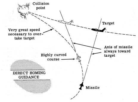
The simplest type of homing guidance and the one we will consider first, is direct homing, in which the missile's course is always directly toward the target. The missile carries radar equipment which, if the axis of the missile is not in line with the target, actuates internal controls to produce appropriate changes in the missile's course. This type of guidance causes the missile to follow a highly-curved pursuit course in overtaking the target. Direct homing is therefore effective against slowly moving or fixed targets. In the case of fast-moving targets, however, it leaves something to be desired, because in such cases very high speed is necessary in the final stages of the missile's flight in order to obtain direct hits.
J-19
INTRODUCTION TO ROCKET AND GUIDED MISSILE FIRE CONTROL
Lead Homing Guidance
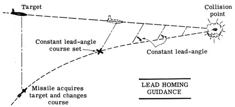
Another type of homing guidance is lead homing guidance. This system employs a more complex homing mechanism than does the direct homing system. The missile's homing equipment actuates controls which cause the missile to acquire and remain on a constant lead-angle course to the target. In other words, once the missile establishes contact with the target, its controls are actuated to bring it to the desired constant lead-angle course. The angle between the missile's course and the L. O. S. from missile to target then remains constant during the latter part of the missile's flight. The speed required of the missile during the final stage of its attack is small as compared with that required of direct-homing missiles.
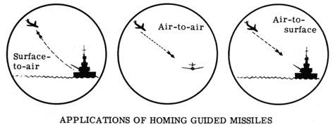
A homing guided missile has the advantage of being able to pursue and accurately attack its target even beyond the sight or radar range of the launching ship or plane. They have certain limitations however. To avoid confusion as to targets, in most cases the missile must be launched in the vicinity of the target and in its general direction. For this reason homing missiles are suitable for surface-to-air and air-to-air attacks against enemy bombers, or air-to-surface attacks against surface craft. They are not effective in air-to-surface or surface-to-surface use against enemy shore installations, since the missile would not know what land object to home on unless brought very close to the target by some other means of control.
J-20
INTRODUCTION TO ROCKET AND GUIDED MISSILE FIRE CONTROL
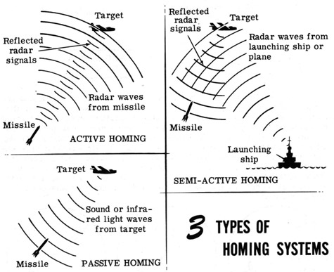
Active, Semi-active and Passive Homing
Homing guidance systems may be classified as active, semi-active and passive. This classification is based on the way in which guidance signals are received by the missile's homing mechanism. Both direct and lead homing missiles may be either active, semi-active or passive.
An active homing missile carries its own radar transmitter and receiver. It sends out radar signals itself and, upon receiving a reflected signal, alters its course to head toward the source of the echo. In semi-active homing, the missile carries only a radar receiver, and responds to signals reflected from the target but transmitted from a radar transmitter carried aboard the launching ship or plane. This method of guidance requires that the target be within radar range of the launching ship or plane. Finally, in passive homing, directing intelligence is obtained from the target alone, as in the case of homing upon a source of noise or infrared light rays. The three types of homing systems, classified in this manner, are shown below.
Note that the two general types of guidance you have found out about so far -pre-set gyro and homing- do not provide for any control of the missile by the launching plane or ship after the missile has been launched. Let's go on and find out about two methods of guidance which do provide exterior control-beam-rider and command guidance systems.
J-21
INTRODUCTION TO ROCKET AND GUIDED MISSILE FIRE CONTROL
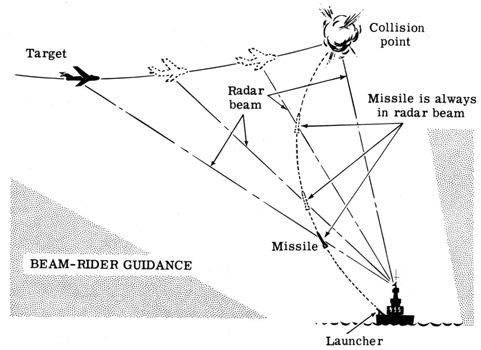
Beam-Rider Guidance Systems
Missiles controlled by means of beam-rider guidance systems are not subject to the direct control of the launching ship or plane. Once the target has been acquired it is tracked automatically by automatic radar tracking devices which keep the radar beam continuously on target. The missile contains mechanisms which, after launching, keep the missile in the radar beam. It thus automatically maintains a collision course by "riding" the radar beam to the target. An automatic homing device may be employed to control the missile during the final stage of its flight. After once having acquired the target on the automatic tracking radar and launching the missile, the launching ship or plane exerts no influence over it other than to destroy it by setting off the explosive charge in the event that it misses the target and is in a position to cause damage to friendly craft or land installations.
The curved flight path followed by the beam-rider guided missile calls for high speed at the end of its flight, but not so much as in the case of direct homing. The beam-rider system is most accurate and effective at relatively short range. This type of guidance system requires that the target remain within radar range of the launching ship or plane until the missile strikes the target. Thus if the target can get out of range before collision, control of the missile is lost, unless a homing device is used to continue the attack. In addition, beam-rider and command guidance systems which control the missile by means of radar or radio waves are subject to jamming or interference by enemy countermeasures.
J-22
INTRODUCTION TO ROCKET AND GUIDED MISSILE FIRE CONTROL
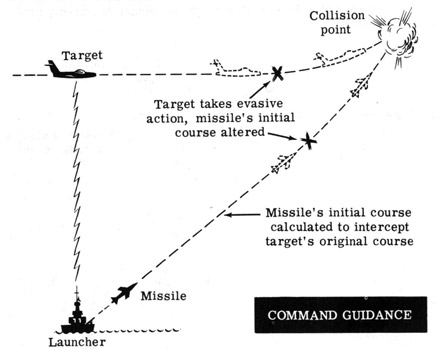
Command Guidance Systems
A system in which a guided missile's flight path to the target is controlled by signals from ground equipment is the command guidance system. In this method of guidance, data as to target position and motion are received by radar and fed to a computer. The missile is then initially launched on a course designed to intercept the target, in a manner similar to the gun director system employed in firing conventional projectiles. Relative positions of target and missile are tracked continuously after launching, and steering orders from computer to missile actuate controls which cause the missile to change course in order to maintain a collision course even when the target takes evasive action.
Now you've been introduced briefly to the various types of missile guidance systems in use today. You've seen how pre-set gyro, homing, beam-rider and command guidance systems operate, and the advantages and limitations of each. You should have a pretty good idea by now of the capabilities of guided missiles when controlled by effective guidance systems. In recent years many advances have been made in the field of guided missiles, and development work is continuing at the present time to explore the possibility of additional applications and to improve the existing weapons. There are many problems which arise in the control of guided missiles that have not been detailed here since they do not fall within the scope of these sheets, and still other problems remain to be solved. But it is enough if you know what a guided missile is and what types of guidance systems are in use at present.
J-23
INTRODUCTION TO ROCKET AND GUIDED MISSILE FIRE CONTROL
Review of Rocket and Guided Missile Fire Control
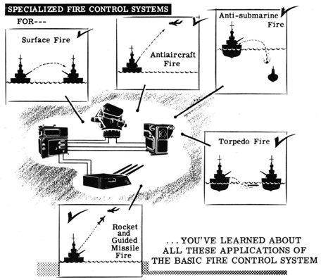
In this section of instruction sheets you found out about rockets and guided missiles and their respective fire control problems. Various types of rockets were described and their applications explained. You saw the similarity between surface-to-surface rocket fire control and conventional gun fire control, and saw how a typical rocket fire control system operates. You learned the difference between rockets and guided missiles, and between rocket and air-duct jet engines. Then you were introduced to various types of guided missiles and saw how they are controlled by several types of guidance systems. So now you've completed, for the present, your study of the specialized fire control problem which applies to rockets and guided missiles. And, at this point, you've also completed your survey of the various specialized applications of the basic fire control system-as it is applied to the control of main battery and antiaircraft guns, antisubmarine weapons, torpedoes and, finally, rockets and guided missiles.
You've come just about to the end of the road in your study of Fire Control Fundamentals. You are not, of course, a fire control expert, topnotch operator or troubleshooter-and you will not be until you have done plenty of practical work with fire control equipment. But you have a pretty good idea of what fire control is all about, and you're ready now to find out how you will learn the details of special fire control equipment. In the next section of these sheets you will find your future work outlined for you.