AN INTRODUCTION TO FIRE CONTROL EQUIPMENT OPERATION
The Basic Components of a Fire Control System
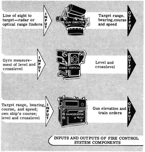
By this time you are undoubtedly well acquainted with the major components of a fire control system-the gun director, rangekeeper, stable vertical and gun turrets. You have seen what the function of each is and how the units are tied together. You know what the basic input to and output from each component is, but you may be wondering how each component works. How does the gun director measure range and bearing? How does the stable vertical measure level and crosslevel? How does the rangekeeper compute corrections to range and deflection? You know what each component does, and you know why it does so; the purpose of the next few sheets is to tell you generally how the director measures range, how the rangekeeper makes calculations, and how the stable vertical measures deck tilt.
To start, let's take a look inside a typical gun director and see what makes it tick.
E-2
AN INTRODUCTION TO FIRE CONTROL EQUIPMENT OPERATION
The Typical Gun Director
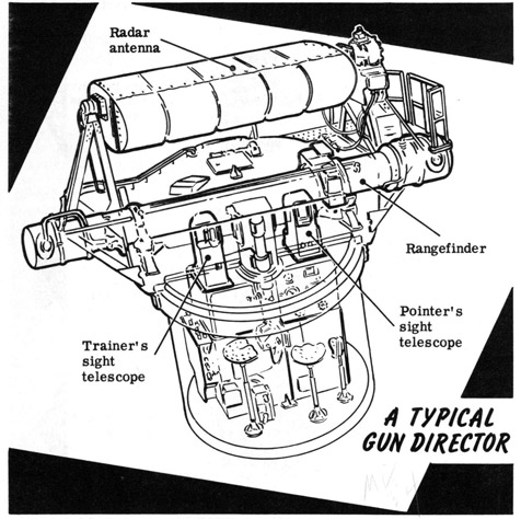
Gun directors vary widely in size, construction and appearance depending upon their application. For instance the director for a battery of 16-inch guns bears little obvious similarity to a director used to control 40-mm antiaircraft guns. But however different in size and appearance, most gun directors contain the same major components. The most important of these components is the radar equipment, which is used to determine both target range and bearing. In the event of failure of the radar system, optical equipment in the director is used to determine present target position. The rangefinder measures range; the sight telescopes fix the L. O. S. and hence determine target bearing and elevation. The optical equipment, however, can only be used under good conditions of visibility.
In some fire control systems the rangefinder may be eliminated and the radar antenna mounted on the gun mount. In this case range determination is always made by means of radar. You will learn more about fire control radar in a later section. Right now let's see how the optical instruments work.
E-3
AN INTRODUCTION TO FIRE CONTROL EQUIPMENT OPERATION
How the Rangefinder Works
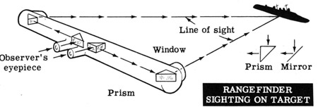
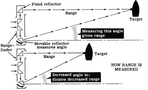
A typical rangefinder consists of a long tube containing optical and mechanical devices which enable it to be focused on the target. Lines of sight travel from the target to each of two windows, located one at each end of the rangefinder, and are reflected to the observer's eyepiece. The line of sight is bent down the tube and into the observer's eyes by means of prisms. A prism is a triangular block of glass which can bend light rays in a manner very similar to a mirror.
You know that in order to see an object clearly you must focus both eyes on it, and that you must change the position of your eyes to focus clearly on objects at various distances from your eyes. This is the principle utilized in the rangefinder to measure the distance to the target. By measuring the angle formed between the lines of sight to the target from each end of the rangefinder when the target is clearly in focus, the range can be determined. Although the rangefinder actually measures this angle, it is calibrated to read range to target directly in yards.
Actual rangefinders are, of course, much more complicated than indicated above. But in basic principle they are all the same.
E-4
AN INTRODUCTION TO FIRE CONTROL EQUIPMENT OPERATION
Pointer's and Trainer's Sight Telescopes
The gun director also houses the trainer's sight telescope and the pointer's sight telescope, as shown in the illustration on sheet 5-2.
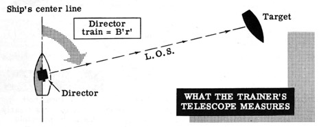
The trainer's sight telescope is used to measure the angle between the ship's centerline and the director L. O. S. This angle is called director train B'r' and is measured clockwise from the ship's bow. The trainer keeps the vertical crosshair of his telescope centered on the target, thus providing a continuous measurement of director train B'r'.
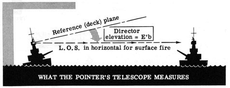
The pointer's sight telescope measures the vertical angle between the L. O. S. and a reference plane parallel to the ship's deck. This angle is called director elevation E'b. The pointer keeps the horizontal crosshair of his telescope centered on the target and thus provides a continuous measurement of director elevation E'b.
Director elevation E'b and director train B'r', together with range R determined by the rangefinder, are three basic quantities required for solution of the fire control problem, and are continuously and automatically supplied to the rangekeeper by the gun director. In surface fire, where the L. O. S. is considered to be horizontal, director elevation becomes a measure of level. E'b is ordinarily disregarded in surface fire since level is corrected for by the stable vertical.
E-5
THIS PAGE MISSING (ripped out) FROM ORIGINAL, ED.
E-6
THIS PAGE MISSING (ripped out) FROM ORIGINAL, ED.
E-7
AN INTRODUCTION TO FIRE CONTROL EQUIPMENT OPERATION
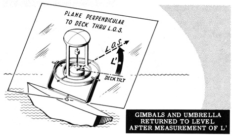
How the Stable Vertical Measures Level
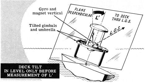
Suppose that the ship is originally in the level position shown on the preceding sheet. If the ship moves in such a way that level is introduced, the level and crosslevel gimbals, umbrella and supporting parts will tilt through the level angle L' but the gyro and its attached magnet will remain vertical as shown below.
As the umbrella coils cut the magnetic lines of force produced by the gyro's magnet a voltage is induced in the coils which acts on a motor geared to the level gimbal and rotates it about its pivots, restoring the level gimbal and other tipping parts to a horizontal position. In so doing the level gimbal is rotated through and measures the level angle L', which measurement is transmitted continuously to the rangekeeper so that the corrections previously described can be made to gun elevation.
E-8
AN INTRODUCTION TO FIRE CONTROL EQUIPMENT OPERATION
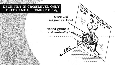
How the Stable Vertical Measures Crosslevel
Now suppose that the ship moves only in crosslevel. The gimbals, umbrella and tipping parts will move as shown below but through the cross-level angle Zh in a vertical plane perpendicular to the line of sight. The gyro and magnet, as before, remain vertical.
In this case, as the umbrella coils cut the field of the gyro's magnet a voltage is induced in the coils which acts on a motor geared to the cross-level gimbal and rotates it about its pivots, restoring the crosslevel gimbal and the umbrella to their level position. Thus the crosslevel gimbal is rotated through and measures the crosslevel angle Zh, which is transmitted continuously to the rangekeeper so that the previously described corrections can be made to gun elevation and train.
Under actual conditions when both level and crosslevel are present, the actions described here and on the preceding sheet occur simultaneously.
E-9
AN INTRODUCTION TO FIRE CONTROL EQUIPMENT OPERATION
An Introduction to Computing Devices
So far in your study of how fire control equipment works, you have learned about the gun director and stable vertical. The remaining component-the rangekeeper-is the most complicated and may appear to you as the most mysterious.
The rangekeeper is not a simple instrument but like all complex machines it is composed of simple component parts. We will not attempt in these sheets to give a complete detailed description of the rangekeeper and all of its many operations. We will only attempt to give you an idea of (1) what basic computing devices make up a typical rangekeeper, and (2) how these computing devices work.
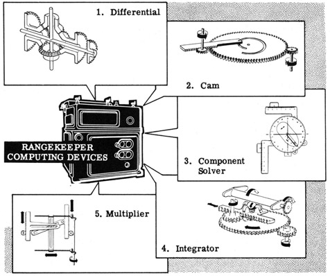
The five basic computing devices used in a rangekeeper are (1) the differential, (2) the cam, (3) the component solver, (4) the integrator, and (5) the multiplier.
On the following sheets each of these devices will be briefly described and their operating principle discussed. It would be impossible to explain the details of their construction and operation and the many variations of these mechanisms in these few sheets and we will not attempt to do so. You will learn the details of operation later in your course on fire control basic mechanisms.
E-10
AN INTRODUCTION TO FIRE CONTROL EQUIPMENT OPERATION
The Mechanical Differential and How It Works
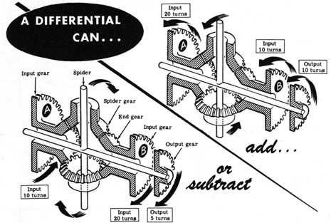
A differential is a mechanism which can add and subtract numbers. It adds the total revolutions of two shafts, or subtracts the total revolutions of one shaft from the total revolutions of another shaft, and delivers the answer by positioning a third shaft. It will add or subtract any number of revolutions, or fractions of single revolutions, continuously and accurately.
Shown below is a simplified diagram of a differential, showing the principal parts. When both input gears turn in the same direction, they turn the spider and hence the output gear in that direction and add the two inputs. When the input gears turn in opposite directions, the spider and hence the output gear will turn in the direction of the largest input by an amount equal to the difference in the inputs.
You will note from the illustration that the output of the differential is one-half of the sum or difference of the inputs. This is always true, due to the construction of the device. Thus, when input gear A turns 20 revolutions counterclockwise and input gear B turns 10 revolutions counterclockwise, the output is half the sum, or 15 revolutions counterclockwise (10 plus 20, divided by 2). Similarly, when input gear B turns 20 revolutions clockwise and input gear A turns 10 revolutions counterclockwise, the output is half the difference, or 5 revolutions clockwise (20 minus 10, divided by 2).
A great number of mechanical differentials are used in Navy fire control equipment. A single rangekeeper may use twenty four or more differentials to perform the various additions and subtractions required for the solution of the fire control problem.
E-11
AN INTRODUCTION TO FIRE CONTROL EQUIPMENT OPERATION
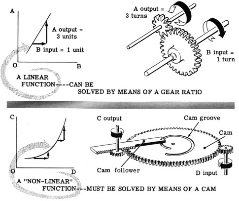
What Cams Do and How They Work
Gears can be used to convert one value to another when they are directly proportional. Differentials can add or subtract quantities when they are represented by shaft rotation. However, in the fire control problem there are quantities which are related in a manner more complex than by simple proportion. For example, drift is a "non-linear" function of range-drift increases more rapidly for equal changes in range at high values of range. When one of two quantities which are related by a "linear" function is known, the other can be found by a simple gear ratio. However, a cam is required to find the unknown of two quantities which are related by a nonlinear function.
A typical cam is shown at the lower right of the illustration above. The cam is a rotating or sliding device whose operating surface is cut to give the desired output for any input. The output is taken off by a cam follower which rides in a groove or slot in or on the outside contour of the cam.
There are many types of cams, varying considerably in construction and operation depending on the particular job for which they were designed. But all cams serve the same basic function-that of yielding as its output the unknown of two quantities which are related by a non-linear function, when the known quantity is fed into the cam as the input.
E-12
AN INTRODUCTION TO FIRE CONTROL EQUIPMENT OPERATION
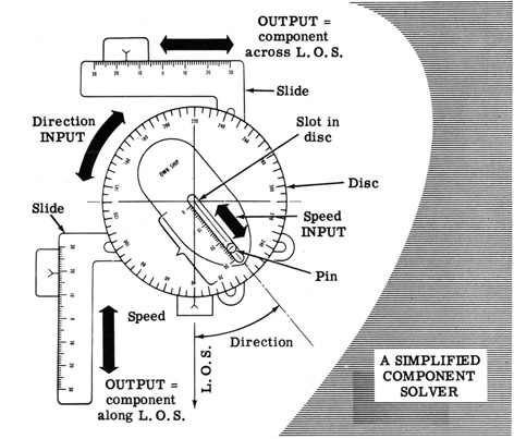
The Function of a Component Solver
When we discussed the solution of the fire control problem, you saw that own ship target and wind motions must be resolved into components along and across the line of sight. The component solver is a mechanical device which resolves quantities into such components automatically and continuously.
There are two inputs to and two outputs from the component solver. The inputs are the original motion's speed and direction. The direction input is fed into the device by rotating a disc so that a slot cut in the disc points in the same direction as the motion, with respect to the L. O. S. The speed input is fed in by positioning a pin which slides in the slot. This pin then moves two slides in a manner by which they continuously indicate the components which are parallel to and perpendicular to the L. O. S.
Component solvers similar in operating principle to the one shown above are used to automatically solve for own ship, target and wind velocity components. The disc is turned by means of a gear on the end of a shaft, and the pin is moved radially from the center of the disc by means of a screw or cam. The outputs-the components-may be indicated on a scale as shown but the movement of the slides is generally used as direct input to other computing devices in the rangekeeper.
E-13
AN INTRODUCTION TO FIRE CONTROL EQUIPMENT OPERATION
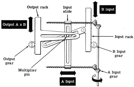
The Mechanical Multiplier and How It Works
In solving a fire control problem it is often necessary to multiply two continually changing numbers and have the answer instantly and at all times. The device used to accomplish this is called a "multiplier. "
Multipliers take two continuously changing input values and deliver one output that, at every instant, is the product of the two changing inputs. The multiplier most commonly used in Navy rangekeepers is the screw-type multiplier. The input gears position an input slide and an input rack, as shown below. The combined motion of these parts moves the multiplier pin, which in turn positions the output rack, and thus turns the output gear.
THE SCREW - TYPE MULTIPLIER
Because of space considerations the output of multipliers usually is a proportional fraction of the product of the inputs. A suitable gear ratio then increases the answer to its full value and delivers it as the input to another rangekeeper computing device.
In addition to the screw-type multiplier illustrated above, there are several other types of multipliers. As with cams and component solvers, all multipliers use the same basic principles of operation. The other types of multipliers are (1) the rack-type, (2) the sector-type, and (3) the single-cam computing multiplier.
E-14
AN INTRODUCTION TO FIRE CONTROL EQUIPMENT OPERATION
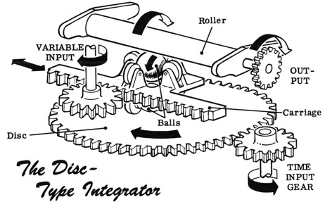
The Function of the Integrator
Suppose you knew that the range rate of a surface target moving toward your ship was 10 yards per second. If you were asked how far it moved toward you in ten seconds you would say 100 yards. You simply multiplied rate by time to get distance-range rate multiplied by time equals total change in range.
Looking at it another way, you could say you performed a simple "integration." You added up all the small range changes (yards per second) over a period of time to give you the total change in range. This process of adding a continuous sequence of small changes is called "integration."
The mechanical "integrator" used in rangekeepers performs this computation automatically. There are two inputs to the integrator-one is constant and represents the constantly increasing time; the other input is variable, and may be range rate or some other quantity which varies with time.
The variable input controls the positioning of the carriage on the disc. The time input gear rotates the disc at a constant speed. The disc then drives the balls by friction, which in turn rotate the roller to drive the output gear. The amount of rotation of the balls and roller depends on the distance from balls to center of disc, and hence on the variable input.
The construction of actual integrators, as well as the other basic mechanisms described on the preceding sheets, is more complicated than the illustrations may indicate. You will learn the details of construction later on in a course in fire control basic mechanisms; here we have presented only basic concepts and elementary construction features.
E-15
AN INTRODUCTION TO FIRE CONTROL EQUIPMENT OPERATION
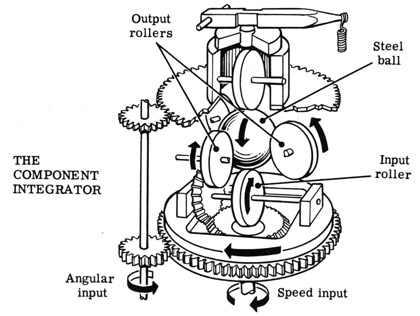
The Component Integrator
The component integrator combines some of the functions of the integrator discussed on the preceding sheet and the component solver described previously. Like the component solver it receives two variable inputs-the magnitude and direction of a quantity such as own ship's motion or true wind. The outputs of the component integrator, like those of the component solver, represent the two components of the input quantity. These components are at right angles to each other and lie across a fixed axis such as the line of sight or ship's axis. Changes in the values of these components are continuously accumulated as in the disc-type integrator.
The component integrator is somewhat similar in construction to the disc-type integrator, but it has only one steel ball and five rollers. The ball is driven by the input roller mounted under the ball; the ball itself drives the two output rollers, which are mounted in the frame on horizontal shafts at right angles to each other. The other two rollers are simply guide rollers which hold the ball in firm contact with the input and output rollers.
The input roller introduces the linear input, is positioned by the speed input shaft through a set of bevel gears and controls the speed of rotation of the ball. The angular (position) input shaft controls the position of the input roller shaft with respect to the two output roller shafts. The combined motion of the two inputs is reflected in the relative values of the two component outputs. The advantage of the component integrator over the component solver is that its construction makes possible the resolution of rapidly changing values over a wider range than was possible with the simpler component solver.
E-16
AN INTRODUCTION TO FIRE CONTROL EQUIPMENT OPERATION
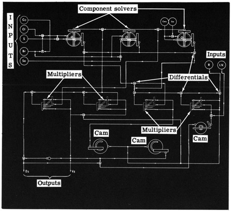
How the Basic Mechanisms Work Together in the Rangekeeper
Now that you know how each of the five basic computing devices functions you are probably wondering how they are tied together. The illustration below shows the flow of quantities within a simplified typical rangekeeper. The mechanisms are represented symbolically, and the arrows represent mechanical or electrical transfer of values. The inputs to the rangekeeper are range (R), initial velocity (I. V.), wind speed (Sw), wind direction (Cws), own ship's course (Co), target course (Ct), own ship's speed (So), target speed (S), and relative target bearing (Br). Rangekeeper outputs are sight angle (Vs) and sight deflection (Ds).
SIMPLIFIED TYPICAL RANGEKEEPER MECHANISMS
It is not expected that you will memorize the above diagram. It is included here only to give you an idea of what goes on inside a typical rangekeeper.
E-17
AN INTRODUCTION TO FIRE CONTROL EQUIPMENT OPERATION
Review of Fire Control Equipment Operation
In this section you learned a little more about the components of a fire control system. You took a quick look at the inside of a gun director, a stable vertical, and a rangekeeper, and should have an idea of how they work. Such terms as crosslevel gimbal, differential and integrator should be familiar, and although you may not know the details of the construction of such fire control equipment components, you do know what they are, how they work, what piece of equipment they are used in, and their functions.
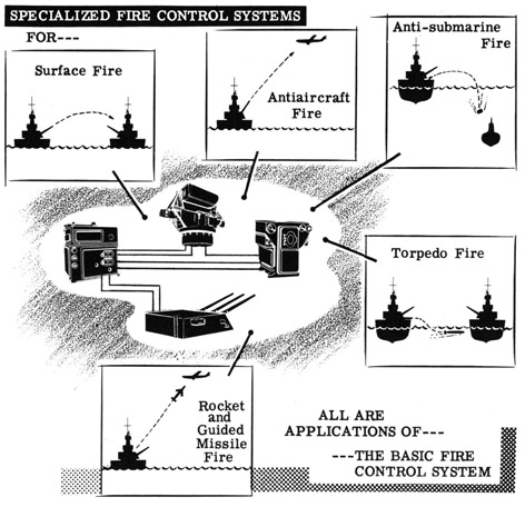
Until now, we have been considering general fire control equipment. We have discussed the various elements of a fire control system without relating them to a specific application aboard ship. In the following and succeeding sections you will learn about the application of the general principles and system components discussed here and in the preceding sections.
Since we have considered so far only surface fire control, the logical thing to do is to start studying applications by considering main battery fire control systems which are used to control surface fire.