ROTATING DOG
(Lever Type and Rack and Pinion Type)
HEINTZ MFG. CO.
Front Street & Olney Ave., Philadelphia, Penna.
BUREAU OF SHIPS • NAVY DEPARTMENT • WASHINGTON, D. C.
INTRODUCTION
This instruction book presents all information necessary for installation of Sliding Dog Lever Type, Rotating Dog Lever Type and Rotating Dog Rack and Pinion Type doors and their maintenance by shore activities and forces afloat. Through its use these doors can be kept in smooth, easy and efficient operating condition.
•
SHIP PROGRAM SHIPS USING HEINTZ QUICK ACTING WATERTIGHT DOORS
SECTION 1 DESCRIPTION of the HEINTZ QUICK-ACTING WATERTIGHT DOORS
THERE ARE THREE TYPES OF HEINTZ QUICK ACTING DOORS
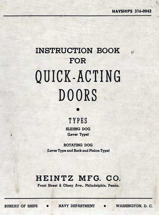
(1) Sliding Dog Lever Type Door, Fig. 1, page 1, and Fig. 2, page 2.
(2) Rotating Dog Lever Type Door, Fig. 1, page 1, and Fig. 4, page 4.
(3) Rotating Dog Rack and Pinion Type Door, Fig. 6, page 6, and Fig. 8, page 8.
All of the doors operate quickly, easily and efficiently when correctly installed and adjusted, and when in dogged position make compartments tight.
All illustrations of replacement operations refer to the 26" x 66" Doors. The doors are made in various sizes and combinations of dogs, depending upon pressure requirements and bulkhead door openings.
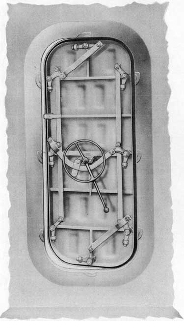
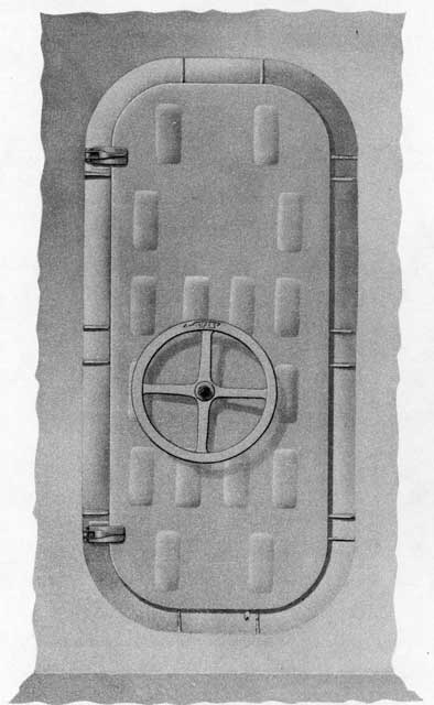
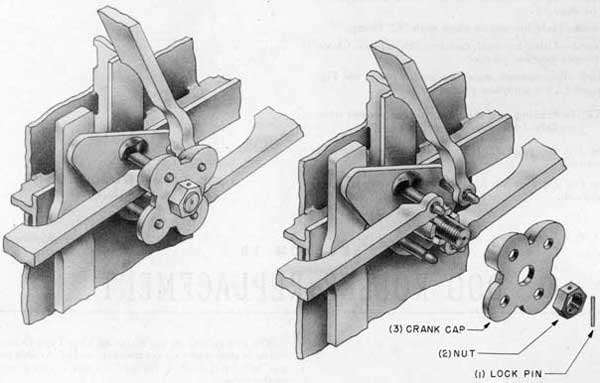
Fig. 1-Outside view of Sliding Dog and
Rotating Dog Lever Type Doors.
2
SLIDING DOG LEVER TYPE DOOR
This door is dogged or undogged by a 3/4 turn of
the hand lever, with minimum power requirement. The dogs are fully extended over the wedge before the final action forces the dogs down on the wedge.
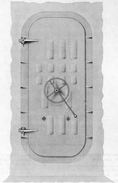
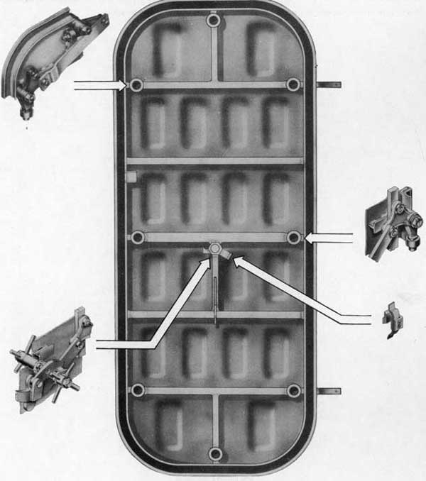
Fig. 2-Inside view, Sliding Dog Lever Type Door.
HERE IS THE COMPLETE DOGGING OPERATION (Fig. 2, page 2):
(1) Closing the door against bulkhead frame,
(a) trips the interlock,
(b) releasing the operating mechanism.
(2) Turning the hand lever 3/4 turn,
(a) rotates the toggle arm,
(b) actuating the connecting rod, this
(c) rotates the dog crank which
(d) extends the dogs out over the wedge,
(e) lifting the inner end of dog bar by the cam on the dog crank,
(f) forcing the outer end of dog down on wedge,
(g) forcing knife edge into rubber gasket.
(h) The hand lever is held in final position by the toggle arm spring.
3
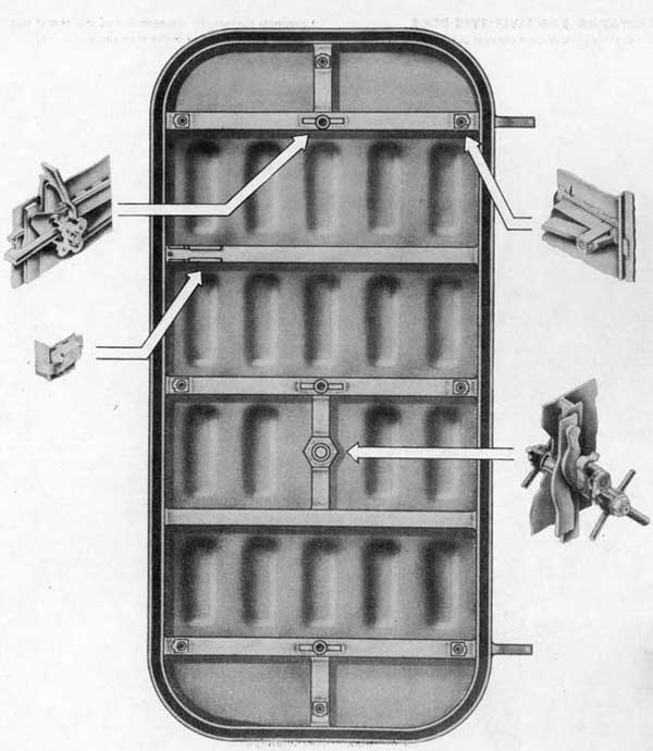
Fig. 3-inside view, Sliding Dog Lever Type Door,
showing shell with main assemblies pulled out.
4
ROTATING DOG LEVER TYPE DOOR
On this type of door the ease of operation is obtained
through the toggle arrangement of the center mechanism and the use of roller type dogs.
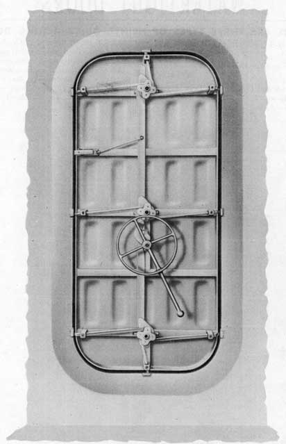
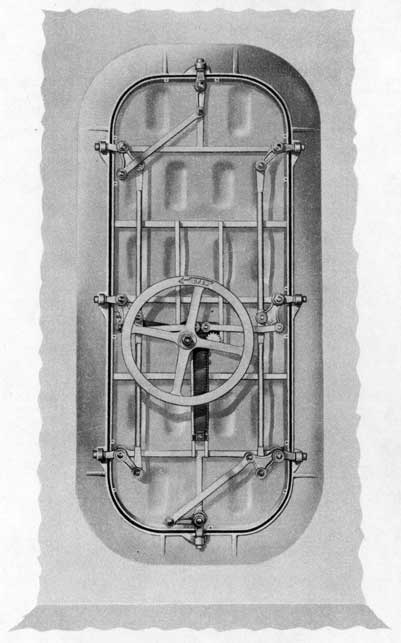
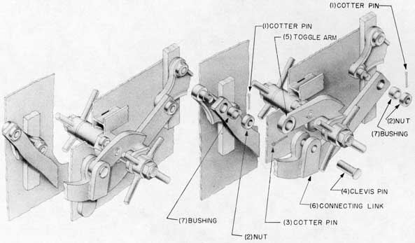
Fig. 4-Inside view, Rotating Dog
Lever Type Door.
HERE IS THE COMPLETE DOGGING OPERATION (Fig. 4, page 4):
(1) Closing the door against bulkhead frame,
(a) trips the interlock,
(b) releasing the operating mechanism.
(2) Turning the hand lever 3/4 turn,
(a) rotates the toggle arm,
(b) actuating the linkage system,
(c) pulling the dogs around on their pivots;
(d) the dog rollers roll up on the wedges,
(e) forcing knife edge into rubber gasket.
(f) The toggle arm spring acts as a limit stop that holds the hand lever in final position.
5
Fig. 5-Inside view, Rotating Dog Lever Type Door,
showing shell with main assemblies pulled out.
6
ROTATING DOG RACK AND PINION TYPE DOOR
On this type of door the ease of operation is obtained
through the use of a rack and pinion mechanism and roller type dogs. Approximately two turns of the hand-wheel completes operation.
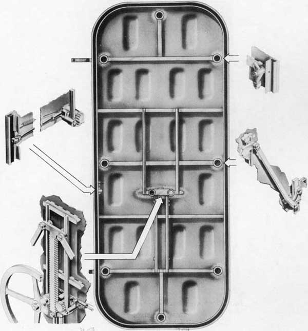
Fig. 6-Inside view, Rotating Dog Rack
and Pinion Type Door.
HERE IS THE COMPLETE DOGGING OPERATION (Fig. 6, page 6):
(1) Closing the door against bulkhead frame,
(a) trips the interlock trigger,
(b) lifting the pawl from the teeth of the pinion, unlocking the mechanism.
(2) Turning either handwheel
(a) rotates the pinion,
(b) moving the rack down,
(c) actuating the linkage system,
(d) pulling the dogs around on their pivots;
(e) the dog rollers roll up on the wedges,
(f) forcing knife edge into rubber gasket.
7
Fig. 7-Inside view, Rotating Dog Rack and Pinion Type Door,
showing shell with main assemblies pulled out.
8
The test pressures for the doors range from 5 to 25 pounds per square inch. The pressure factor of the doors depends upon the type and number of dogs and
their location; the size of the door; the size, number
and spacing of the structural ribs of the door panel,
and the number of reinforcements in the door frame.
Fig. 8-Outside view of Rotating Dog Rack and Pinion Type Door.
STANDARD SIZES All Types Heintz Quick Acting Doors
Size of Door
No. of Dogs
18" x 36"
6
26" x 45"
6
26" x 45"
8
26" x 48"
6
26" x 54"
6
26" x 54"
8
26" x 66"
6
26" x 66"
8
26" x 66"
10
Size of Door
No. of Dogs
30" x 54"
6
30" x 54"
6
30" x 60"
8
30" x 66"
8
30" x 66"
10
36" x 57"
8
36" x 66"
8
42" x 57"
10
9
SECTION 2 INSTALLATION OF DOOR
The door is fabricated to a prescribed degree of accuracy and must be installed with careful attention to prescribed procedure.
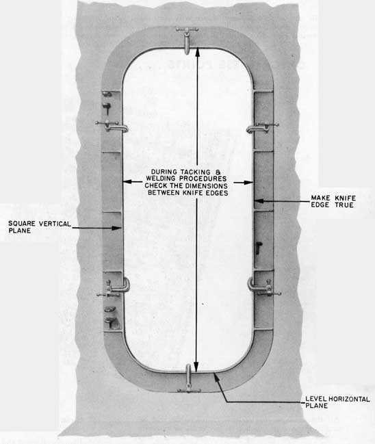
A TYPICAL INSTALLATION IS AS FOLLOWS (Fig. 9):
(1) Straighten the bulkhead around the edges of the door opening.
(2) Check with a straight edge across and along the edges of the bulkhead opening, to the exclusion of a 3/32" feeler.
(3) Clamp door frame in place, center frame, square up to vertical knife edge and level up to horizontal knife edge.
(4) Using arc weld, tack door frame in place following proper tacking procedure. During tacking, check dimensions between knife edges.
(5) Permanently arc weld door frame in place following proper welding procedure. During welding, check knife edges for distortion.
(6) With a straight edge, check knife edges to the exclusion of a 1/16" feeler. If necessary to straighten, use soft mallet.
(7) Lift door onto hinges, see Figs. 11 and 12, page 11.
(8) Chalk-test knife edge contact on rubber gasket.
(9) Adjust rubber gasket compression, see Figs. 15 and 16, page 13.
WELDING ELECTRODE NOTE
For welding corrosion-resisting steel frame to any bulkhead, use only 25-20 welding electrode, Grade IV-DC BUSHIPS Ad Interim Specification 46E4 (INT) of 15 April 1944 and amendment 2 of 15 August 1944 or later issue. For medium carbon steel frame, use medium steel welding electrode BUSHIPS Ad Interim Specification 46E3 (INT) of 1 November 1945 or later issue. All welding shall be in accordance with the applicable requirements of General Specifications, Appendix 5, Parts I and II.
INSTALLATION NOTE
When installing the Sliding Dog Lever Type Door, the bulkhead must be braced from bulkhead stiffeners to door frame along the vertical sides. This is done so that the deformation of the bulkhead will not produce a change in the size of the door opening sufficient to permit the dogs to slide off the wedges when subjected to heavy loads.
Door frame in place ready for tacking and welding.
10
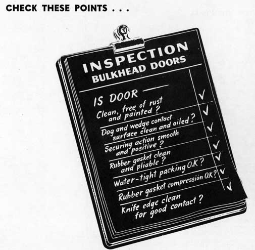
SECTION 3 INSPECTION, MAINTENANCE and REPAIRS
Periodic inspection and maintenance will keep the Quick Acting Doors watertight and insure smooth, easy operation. Each door should be inspected weekly,
and necessary maintenance should be completed without delay. A weekly routine of inspection, maintenance and repairs, carried out systematically is desirable.
All the materials for routine maintenance will be found in ships stores: carbon-tetrachloride or kerosene and paint thinner for removing grease, excess paint and other foreign matter, steel wool, 00 emery cloth and some clean wiping rags.
HERE IS AN EXAMPLE OF GOOD ROUTINE INSPECTION AND MAINTENANCE:
(1) Wipe off all dirt, grease and foreign matter with a wiping cloth dampened with carbon-tetrachloride or kerosene.
(2) Scrape rust off all parts of the door.
(3) Clean contact surface of dog and dog wedge with steel wool and wipe both surfaces with an oily cloth, leaving a thin film of oil.
(4) Clean rust and paint off knife edge contact surface with 00 emery cloth.
(5) Remove all paint and rust from rubber gasket. It should be clean and pliable.
(6) Examine all moving parts for excess wear or damage. If necessary, REPLACE NOW.
(7) Operate door and check for smooth and positive dogging action.
(8) Check compression between knife edge and rubber gasket. If adjustment is necessary, see Figs. 15 and 16, page 13.
(9) Lubricate teeth of rack, pinion on Rack and Pinion Type Door, using rust-inhibitive grease.
1
11
SECTION 4 WEDGES REPLACEMENT
The wedges on all doors are the inclined surfaces, or points, where the dogs exert the pressure that forces the knife edge into the rubber gasket forming the watertight seal.
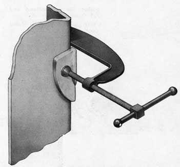
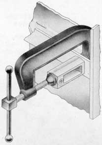
Fig. 10-Wedge ready for welding,
Rotating Dog Type Door.
HOW TO REPLACE WEDGES ON ALL TYPES OF HEINTZ DOORS
First-Chip old wedge from door frame.
Second-Chip clean all old weld metal from wedge seat on frame.
Third-Hold wedge in place with "C" clamp, see Fig. 10.
Fourth-Using arc weld, tack wedge in place. Dog door and check for proper wedge position.
Fifth-Permanently weld wedge in place.
Sixth-Check rubber compression all around door, see Figs. 15 and 16, page 13.
NOTE: In tacking and welding, follow proper procedure (see welding note, page 9).
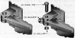
SECTION 5 HINGE PIN REPLACEMENTTHERE ARE TWO TYPES OF HINGES ON THE HEINTZ DOORS:
1.-The conventional type with the elongated hole in the hinge blade.
2.-The Non-Sag Hinge which is designed to minimize sagging and misalignment of the door and to reduce frictional wear on the hinge pin.
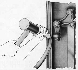
HOW TO REPLACE HINGE PIN:
To Dis-assemble:
Dog Door lightly.
(1) File off peen of pin and remove hinge pin collar.
(2) Remove hinge pin.
(3) Slide washer from between hinge pad and hinge blade and inspect for scoring or excessive wear.
Fig. 11-Hinge, assembly and exploded views,
conventional type hinge.
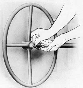
To Re-assemble:
(3) Replace washer between lower hinge pad and hinge blade.
(2) Line up hinge pin holes and insert hinge pin.
(1) Set new collar in place and peen over hinge pin.
Test for free swing of door.
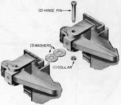
Fig. 12-Hinge, assembly and exploded views,
Non-Sag Type Hinge.
12
SECTION 6 RUBBER GASKET REPLACEMENT
The rubber gasket makes the door watertight where the door gasket meets the door frame knife edge.
The outer gasket retaining edge is part of the door panel, minimizing the danger of water leakage at this point. The inner gasket retaining edge is a bulb angle of one section which acts as a stiffener around the door, thus minimizing bulge or distortion of the door panel under water pressure.
The rubber gasket and method of replacement are the same for all Heintz Doors covered in this manual.
NOTE: When replacing rubber gasket, remember these Hints:
(1) Gasket joint should be at center top of door.
(2) Wet gasket with water and it will slide in place easily.
(3) Do not stretch rubber gasket when inserting in seat.
(4) Cut one inch too long, pull out part way, reinsert from cut end, forcing excess inch in place.
HOW TO REPLACE RUBBER GASKET, ALL HEINTZ QUICK ACTING DOORS (Fig. 13):
First-Insert screw driver at joint and pry out enough for hand-hold, pull out rest of gasket by hand.
Second-Clean out all foreign matter around gasket seat.
Third-Insert new gasket, use soft hammer and wooden wedge (see NOTE above).
Fourth-Check to be sure gasket is properly seated in retainers all around door.
Fig. 13-Rubber gasket replacement,
all Heintz Quick Acting Doors.
SECTION 7 PACKING REPLACEMENT
Fig. 14-Installing Packing.
The packing is the medium for making the door watertight at the point where the outside handwheel or hand lever shaft pierces the door.
INSTALLING PACKING, ALL HEINTZ QUICK ACTING DOORS (Fig. 14):
From Outer Side of Door:
First-Remove packing plunger from outside operating lever (handwheel) shaft.
Second-Insert stick of packing. If stick packing is not available, roll bulk packing into a string form and pack into hole of shaft (use N.D. Spec. 33P29 Symbol 1425).
Third-Replace packing plunger and screw flush to shaft surface.
13
SECTION 8 RUBBER GASKET COMPRESSION ADJUSTMENT
The compression between the knife edge and rubber gasket may be varied by the compression adjustment on each dog on all Heintz Doors.
To determine proper preliminary adjustment, hold a piece of paper under dog, between knife edge and gasket, close door and hold in closed position by hand. Do not dog door. Adjust compression so that paper may
be pulled from between gasket and knife edge with a maximum drag. After preliminary adjustment has been completed for each dog, fully dog door and adjust each dog for a 1/8" depression of the knife edge onto the rubber gasket. The 1/8" depression may be determined by measuring a 1/8" pull-in of the door to the frame. Use a depth gauge or combination square and straight edge to measure from outside door panel to frame.
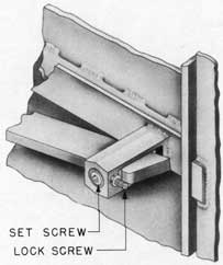
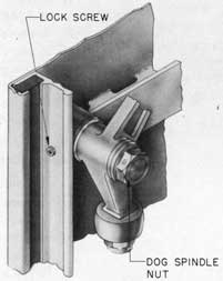
HOW TO ADJUST RUBBER GASKET COMPRESSION, ROTATING DOG TYPE DOORS (Fig. 16):
First-Back lock screw out part way, using Allen wrench.
Second-Turn dog spindle nut clockwise for more compression, counter-clockwise for less compression.
Third-Determine proper compression adjustment (see above).
Fourth-Tighten lock screw to lock compression adjustment.
Fig. 15-Rubber gasket compression adjustment,
Sliding Dog Lever Type Door.
HOW TO ADJUST RUBBER GASKET COMPRESSION, SLIDING DOG LEVER TYPE DOOR (Fig. 15):
First-Back lock screw out part way, using Allen wrench.
Second-Turn set screw, with Allen wrench, clockwise for more compression, counter-clockwise for less compression.
Third-Determine proper compression adjustment (see above).
Fourth-Tighten lock screw to lock compression adjustment.
Fig. 16-Rubber gasket compression adjustment,
Rotating Dog Type Doors.
SECTION 9 BUSHING REPLACEMENT
The bushings on all doors are made of oil-impregnated metal and are self-lubricating; they act as bearings for the moving parts.
During the replacement of any part the inspection of the bushings is regular procedure. Any sign of failure indicates the necessity of replacement.
Inspect bushing for cracks, breaks, wear or loose fit.
Remove bad bushing by driving out, using soft hammer and a piece of bar stock.
To Replace Bushing:
Insert proper bushing; see spare parts list.
Drive bushing home, using soft hammer and bushing set.
14
SECTION 10 HAND LEVER SHAFT REPLACEMENT
The hand lever shaft on the Lever Type Door is a rugged part and ordinarily needs little or no attention. However, it may be damaged during shifting of cargo or equipment, which will necessitate its replacement.
HOW TO REPLACE HAND LEVER SHAFT, SLIDING DOG LEVER TYPE DOOR (Fig. 17):
To Dis-assemble:
From outer side of door:
(1) Remove packing plunger.
(2) Remove outside hand lever nut.
(3) Slide off outside hand lever wheel.
(4) Remove bushing, inspect and renew if necessary.
From inner side of door:
(5) Remove inside hand lever nut.
(6) Slide off inside hand lever wheel.
(7) Remove lock pin from toggle arm pin.
(8) Remove toggle arm pin.
(9) Pull toggle arm over.
(10) Replace new hand lever shaft.
(11) Remove bushing, inspect and renew if necessary.
(12) Inspect two toggle arm bushings-renew if necessary.
To Re-assemble:
From inner side of door:
(11) Replace bushing.
(10) Replace new hand lever shaft.
(9) Slide toggle arm in place.
(8) Replace toggle arm pin, line up lock pin holes.
(7) Replace lock pin in toggle arm pin.
(6) Replace inside hand lever wheel.
(5) Replace inside hand lever nut and pull tight.
From outer side of door:
(4) Replace bushing.
(3) Replace outside hand lever wheel.
(2) Replace outside hand lever nut, pull tight.
Insert new packing, see page 12.
(1) Replace packing plunger.
Test for smooth operation.
15
Fig. 17-Replacing hand lever shaft,
Sliding Dog Lever Type Door.
16
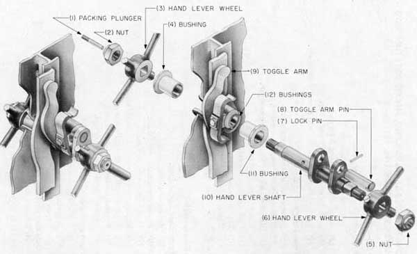
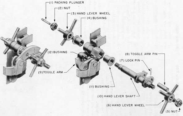
HOW TO REPLACE HAND LEVER SHAFT, ROTATING DOG LEVER TYPE DOOR (Fig. 18):
To Disassemble:
From outer side of door:
(1) Remove packing plunger.
(2) Remove outside hand lever nut.
(3) Slide off outside hand lever wheel.
(4) Remove bushing, inspect and renew if necessary.
From inner side of door:
(5) Remove inside hand lever nut.
(6) Slide off inside hand lever wheel.
(7) Remove lock pin from toggle arm pin.
(8) Remove toggle arm pin.
(9) Pull toggle arm over.
(10) Remove hand lever shaft.
(11) Remove bushing, inspect and renew if necessary.
(12) Inspect two toggle arm bushings, renew if necessary.
To Re-assemble:
From inner side of door:
(11) Replace bushing.
(10) Replace new hand lever shaft.
(9) Slide toggle arm in place.
(8) Replace toggle arm pin, line up lock pin holes.
(7) Replace lock pin in toggle arm pin.
(6) Replace inside hand lever wheel.
(5) Replace inside hand lever nut.
From outer side of door:
(4) Replace bushing.
(3) Replace outside hand lever wheel.
(2) Replace outside hand lever nut.
Insert new packing, see page 12.
(1) Replace packing plunger.
Test for smooth operation.
17
Fig. 18-Replacing hand lever shaft,
Rotating Dog Lever Type Door.
18
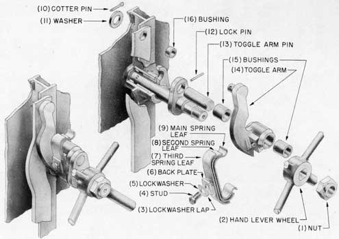
SECTION 11 TOGGLE ARM REPLACEMENT
The toggle arm is the link that rotates when the hand lever is turned. It moves the connecting rod up and down, actuating the dogs.
HOW TO REPLACE TOGGLE ARM, SLIDING DOG LEVER TYPE DOOR (Fig. 19):
To Disassemble:
(1) Remove hand lever nut.
(2) Slide off hand lever wheel.
(3) Force down lap of lock washer.
(4) Remove spring stud. Remove the following:
(5) lock washer,
(6) spring back plate,
(7) third spring leaf,
(8) second spring leaf, and
(9) main spring leaf.
(10) Remove cotter pin behind operating link.
(11) Remove washer behind operating link.
(12) Remove lock pin from toggle arm pin.
(13) Remove toggle arm pin.
(14) Remove toggle arm and bushing as a unit.
(15) Check bushings, renew if necessary.
(16) Inspect bushing in operating link, renew if necessary.
To Re-assemble:
(15) Insert bushing in new toggle arm.
(14) Hold new toggle arm and bushing unit in place.
(13) Replace toggle arm pin, lining up lock pin holes.
(12) Replace lock pin in toggle arm pin.
(11) Connect toggle arm to operating link and replace washer behind operating link.
(10) Replace cotter pin behind operating link.
Hold in place the following:
(9) main spring leaf,
(8) second spring leaf,
(7) third spring leaf,
(6) spring back plate, and
(5) lock washer.
(4) Replace spring stud and pull tight.
(3) Force lap of lock washer on spring stud.
(2) Replace hand lever wheel.
(1) Replace hand lever nut and pull tight.
Test for smooth operation.
Fig. 19-Toggle arm, assembly and exploded views,
Sliding Dog Lever Type Door.
19
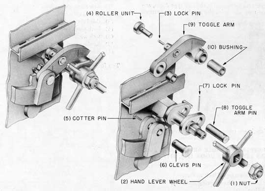
Fig. 20-Replacing toggle arm,
Sliding Dog Lever Type Door.
HOW TO REPLACE TOGGLE ARM, ROTATING DOG LEVER TYPE DOOR (Fig. 20):
To Dis-assemble:
(1) Remove hand lever nut.
(2) Slide off hand lever wheel.
(3) Remove lock pin from roller pin.
(4) Remove roller and roller pin as a unit.
(5) Remove cotter pin from toggle arm clevis pin.
(6) Remove toggle arm clevis pin.
(7) Remove lock pin from toggle arm pin.
(8) Remove toggle arm pin.
(9) Remove toggle arm.
(10) Check bushing, renew if necessary.
To Re-assemble:
(10) Replace bushing in new toggle arm.
(9) Hold new toggle arm in place.
(8) Replace toggle arm pin, line up lock pin holes.
(7) Replace lock pin in toggle arm pin.
(6) Hold toggle arm in position and replace toggle arm clevis pin.
(5) Replace cotter pin in clevis pin.
(4) Replace roller and roller pin unit, line up lock pin holes.
(3) Replace lock pin in roller pin.
(2) Replace hand lever wheel.
(1) Replace hand lever nut.
Test for smooth operation.
20
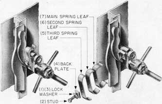
SECTION 12 TOGGLE ARM SPRING REPLACEMENT
TOGGLE ARM SPRING, SLIDING DOG AND ROTATING DOG LEVER TYPE DOORS (Fig. 00)
The toggle arm spring, on both lever type doors, acts as a cushion stop and holds the hand lever in extreme position.
Fig. 21-Toggle arm spring, assembly and exploded views,
Sliding Dog Lever Type Door.
HOW TO REPLACE TOGGLE ARM SPRING, SLIDING DOG LEVER TYPE DOOR (Fig. 21):
To Dis-assemble:
(1) Force down lap of lock washer.
(2) Remove stud from spring assembly.
Lift off following:
(3) lock washer,
(4) back plate,
(5) third spring leaf,
(6) second spring leaf, and
(7) main spring leaf.
To Re-assemble:
Hold following in place:
(7) new main spring leaf,
(6) second spring leaf,
(5) third spring leaf,
(4) back plate, and
(3) lock washer.
(2) Replace stud in spring assembly.
(1) Bend lap of lock washer up on side of stud head.
Test for stop and holding action.
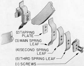
HOW TO REPLACE TOGGLE ARM SPRING, ROTATING DOG LEVER
TYPE DOOR (Fig. 22):
To Dis-assemble:
(1) Remove two machine screws from spring assembly.
Remove the following:
(2) tapping plate,
(3) main spring leaf (spring),
(4) second spring leaf (backing plate), and
(5) third spring leaf (backing plate).
To Re-assemble:
Hold in place the following:
(5) third spring leaf (backing plate),
(4) second spring leaf (backing plate),
(3) main spring leaf (spring), and
(2) tapping plate.
(1) Replace two machine screws in spring assembly and set up tight.
Test for stop and holding action.
Fig. 22-Toggle arm spring, assembly and exploded views,
Rotating Dog Lever Type Door.
21
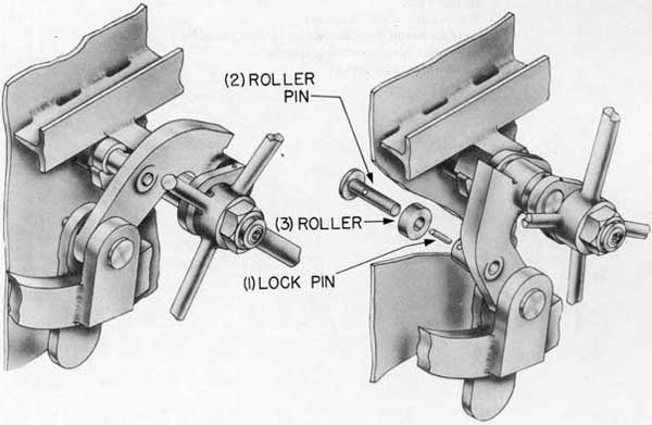
SECTION 13 TOGGLE ARM ROLLER REPLACEMENT
The toggle arm roller on the Rotating Dog Lever Type Door acts as a booster to aid the operating mechanism get over the hump of the operation in dogging the door.
HOW TO REPLACE TOGGLE ARM ROLLER. ROTATING DOG LEVER TYPE DOOR (Fig. 23):
(3) Hold new roller in place.
(2) Insert roller pin and line up lock pin holes.
(1) Replace lock pin in roller pin.
Test for smooth operation.
Fig. 23-Replacing toggle arm roller,
Rotating Dog Lever Type Door.
22
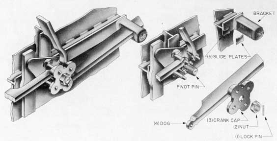
SECTION 14 DOG REPLACEMENT
DOG, SLIDING DOG LEVER TYPE DOOR (Fig. 24):
The Dog on this type door slides out on the wedge. When dog bar is fully extended, the cam on the operating crank raises the inner side of the dog bar, forcing the outer end down on the wedge. This exerts pressure between the knife edge of frame and rubber gasket, creating a watertight seal.
HOW TO REPLACE DOG, SLIDING DOG LEVER TYPE DOOR (Fig. 24):
To Dis-assemble:
(1) Remove lock pin from dog spindle nut.
(2) Remove nut from dog spindle.
(3) Pry off operating crank cap.
(4) Lift dog from pivot pin and pull from out of dog bracket.
(5) Remove two slide plates from dog bracket.
To Re-assemble:
(5) Hold in place two slide plates in dog bracket.
(4) Slide new dog in bracket and insert inner end of dog on pivot pin.
(3) Replace operating crank cap.
(2) Replace nut on dog spindle, line up lock pin holes.
(1) Insert lock pin through dog spindle nut.
Test for smooth, positive action.
Fig. 24-Dog, assembly and exploded views,
Sliding Dog Lever Type Door.
23
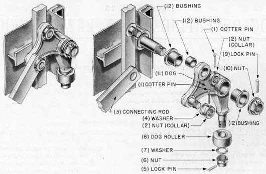
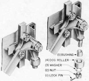
Fig. 25-Dog, assembly and exploded views,
Rotating Dog Lever Type and Rack and Pinion Type Doors.
DOG, ROTATING DOG LEVER TYPE AND RACK AND PINION TYPE DOORS
The dogs on the Rotating Dog Type Doors are pulled around on their pivot by the linkage system and rolling up on the wedge create the pressure at the contact point of the knife edge and rubber gasket.
HOW TO REPLACE DOG, ROTATING DOG LEVER TYPE AND RACK AND PINION TYPE DOORS (Fig. 25):
To Dis-assemble:
(1) Remove cotter pins.
(2) Remove round nuts (collars).
(3) Lift off connecting rod (on lever type door, loosen outside hand lever nut and pull center assembly part way out, on inner side of door, sufficient to lift connecting rod from dog).
(4) Remove washer.
(5) Remove lock pin from dog roller nut.
(6) Remove dog roller nut.
(7) Remove dog roller washer.
(8) Remove dog roller and bushing unit, inspect bushing and renew if necessary.
(9) Remove lock pin on dog spindle nut.
(10) Remove nut on dog spindle.
(11) Remove dog and bushings as a unit.
(12) Inspect three bushings and renew if necessary.
To Re-assemble:
(11) Replace new dog and bushings as a unit.
(10) Replace nut on dog spindle, line up lock pin holes.
(9) Insert lock pin in nut on dog spindle.
(8) Replace dog roller and bushing unit.
(7) Replace dog roller washer.
(6) Replace dog roller nut, line up lock pin holes.
(5) Insert lock pin in dog roller nut.
(4) Replace washer.
(3) Replace connecting rod (on lever type door, push center mechanism back in place, after connecting rod is attached to dog, and tighten outside hand lever nut).
(2) Replace round nuts (collars), line up cotter pin holes.
(1) Replace cotter pins.
Test for smooth operation.
24
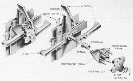
SECTION 15 DOG OPERATING CRANK REPLACEMENT
DOG OPERATING CRANK, SLIDING DOG LEVER TYPE DOOR
The rotation of the operating crank extends the dogs over the wedge, at the same time raising the inner end of dog bar, forcing the outer end down on the wedge.
HOW TO REPLACE DOG OPERATING CRANK, SLIDING DOG LEVER TYPE DOOR (Fig. 26):
To Dis-assemble:
(1) Remove lock pin from crank spindle.
(2) Remove nut from crank spindle.
(3) Pry off operating crank cap.
(4) Lift dogs from pivot pins (do not remove dogs from dog bracket).
(5) Remove cotter pin behind connecting rod.
(6) Remove washer behind connecting rod.
(7) Slide dog operating crank from crank spindle.
(8) Inspect bushings, replace if necessary.
To Re-assemble:
First insert new pivot pins in operating crank, rivet pivot pins flush for loose fit.
(7) Slide new operating crank on crank spindle and insert spindle in connecting rod.
(6) Replace washer on connecting rod spindle.
(5) Insert cotter pin in connecting rod spindle.
(4) Replace dogs on pivot pins.
(3) Replace operating crank cap.
(2) Replace nut on crank spindle, line up lock pin holes.
(1) Insert lock pin through crank spindle nut.
Test for easy, positive action.
Fig. 26-Dog operating crank, assembly and exploded views,
Sliding Dog Lever Type Door.
25
SECTION 16 DOG OPERATING CRANK CAP REPLACEMENT
DOG OPERATING CRANK CAP, SLIDING DOG LEVER TYPE DOOR
The operating crank cap is the outer hub for the operating crank pivot pins. If it is bent or damaged, it may cause binding in the dogging action.
Fig. 27-Dog operating crank cap, assembly and exploded views,
Sliding Dog Lever Type Door.
HOW TO REPLACE DOG OPERATING CRANK CAP, SLIDING DOG LEVER TYPE DOOR (Fig. 27):
To Dis-assemble:
(1) Remove lock pin from dog spindle.
(2) Remove nut from dog spindle.
(3) Pry off operating crank cap.
To Re-assemble:
(3) Replace new operating crank cap.
(2) Replace nut on dog spindle, line up lock pin holes.
(1) Insert lock pin through dog spindle nut.
Test for easy, positive operation.
26
SECTION 17 DOG BRACKET REPLACEMENT
The dog bracket on the Sliding Dog Type Door is the guide the dog slides through. It forms the fulcrum point where the dog end is levered down on the wedge.
HOW TO REPLACE DOG BRACKET, SLIDING DOG TYPE DOOR (Fig. 28):
First-Chip old bracket off door.
Second-Chip clean all old weld metal from bracket seat on door.
Third-Hold bracket in place with "C" clamp.
Fourth-Using arc weld, tack bracket in place. Check for proper bracket position.
Fifth-Permanently weld bracket in place, see Fig. 24, page 22, for complete procedure.
NOTE: In tacking and welding, follow proper procedure (see welding note, page 9).
See Fig. 24, page 22, for bracket disassembly and re-assembly.
See Fig. 15, page 13, for rubber gasket compression adjustment.
Fig. 28-Dog bracket clamped in place
ready for installation.
SECTION 18 DOG ROLLER REPLACEMENT
The dog rollers on the Rotating Dog Type Doors revolve as they move up on the dog wedge. At this point the frictional load is reduced by the turning action of the rollers.
HOW TO REPLACE DOG ROLLER, ROTATING DOG LEVER TYPE AND RACK AND PINION TYPE DOORS (Fig. 29):
To Disassemble:
(1) Remove lock pin from dog roller nut.
(2) Remove dog roller nut.
(3) Remove dog roller washer.
(4) Remove dog roller and bushing as a unit.
(5) Inspect bushing, renew if necessary.
To Re-assemble:
(4) Replace new dog roller and bushing as a unit.
(3) Replace dog roller washer.
(2) Replace dog roller nut, line up lock pin holes.
(1) Insert lock pin through dog roller nut.
Test for smooth operation.
Fig. 29-Dog roller assembly and exploded views,
Rotating Dog Lever Type and Rack and Pinion Type Doors.
27
SECTION 19 CENTER MECHANISM CONNECTING LINK
REPLACEMENT
The center mechanism connecting link on the Rotating Dog Lever Type Door connects the toggle arm of the operating mechanism and the linkage system, which moves the dogs on their pivots. The link on the Rotating Dog Rack and Pinion Type Door connects the rack of the operating mechanism and the linkage system which dogs and undogs the door.
HOW TO REPLACE CENTER MECHANISM LINK, ROTATING DOG RACK AND PINION TYPE DOOR (Fig. 30):
To Dis-assemble:
(1) Remove cotter pins from link studs.
(2) Remove collars from link studs.
(3) Lift off link.
(4) Check bushings, renew if necessary.
To Re-assemble:
(4) Insert bushings in new link.
(3) Slide new link on link studs.
(2) Replace collars on link studs, line up cotter pin holes.
(1) Insert cotter pins.
Test for smooth, positive action.
Fig. 30-Center mechanism link, assembly and exploded views,
Rotating Dog Rack and Pinion Type Door.
28
HOW TO REPLACE CENTER MECHANISM CONNECTING LINK, ROTATING DOG LEVER TYPE DOOR (Fig. 31):
To Dis-assemble:
(1) Remove cotter pins from connecting rod stud nuts.
(2) Remove round nuts from connecting rod studs.
(3) Remove cotter pin from clevis pin.
(4) Pull out clevis pin.
(5) Lift up toggle arm.
(6) Slide out connecting link.
(7) Check bushings, renew if necessary.
To Re-assemble:
(7) Replace bushings in new connecting link.
(6) Slide new connecting link on connecting rod studs, holding toggle arm up.
(5) Put toggle arm in place.
(4) Insert clevis pin through connecting link and toggle arm, line up cotter pin holes.
(3) Insert cotter pin in clevis pin.
(2) Replace round nuts on connecting rod studs, line up cotter pin holes.
(1) Insert cotter pins through connecting rod stud nuts.
Test for smooth, positive action.
Fig. 31-Center mechanism connecting link, assembly and exploded views,
Rotating Dog Lever Type Door.
29
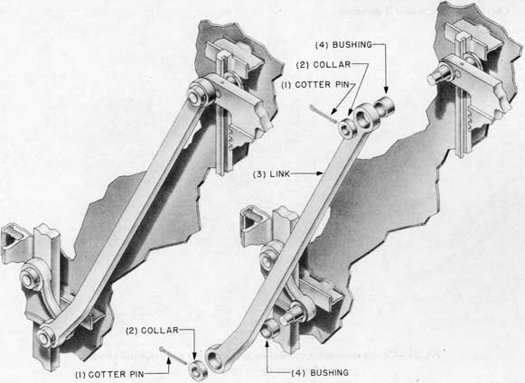
SECTION 20 LINK REPLACEMENT
The link, on the Rotating Dog Type Doors, connects the bell crank to the dog or the bell crank to another bell crank. It is part of the linkage system that rotates each dog on its axis.
The replacement of the link is practically the same for both Rotating Dog Type Doors.
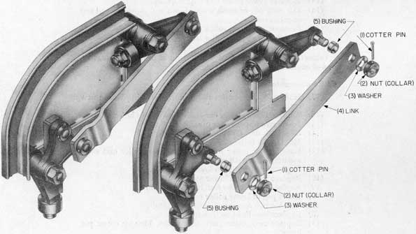
HOW TO REPLACE LINK ROTATING DOG DOORS (Fig. 32):
To Dis-assemble:
(1) Remove cotter pins from stud nuts (collars).
(2) Remove round nuts (collars) from studs.
(3) Remove washer from studs (no washers on the Rack and Pinion Type Door).
(4) Lift off link.
(5) Check bushings, renew if necessary.
To Re-assemble:
(5) Insert bushings in new link.
(4) Place new link on studs.
(3) Replace washers on studs.
(2) Replace round nuts (collars) on studs, line up cotter pin holes.
(1) Insert cotter pins in round nuts (collars).
Test for positive and easy action.
Fig. 32-Link assembly and exploded views,
Rotating Dog Lever Type Door.
30
SECTION 21 RACK REPLACEMENT
The rack on the Rack and Pinion Type Door is the gear mechanism that is moved up and down by the pinions when handwheel is turned. It actuates the linkage system that turns the dogs.
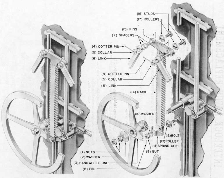
HOW TO REPLACE RACK, RACK AND PINION TYPE DOOR (Fig. 33):
To Dis-assemble:
(1) Remove two handwheel nuts.
(2) Remove washer from handwheel spindle.
(3) Slide off handwheel, pinion and bushing unit.
(4) Remove two cotter pins from link spindles.
(5) Remove two collars from link spindles.
(6) Lift over two links.
(7) Remove four spacers from link spindles.
(8) Remove pin from lower roller nut.
(9) Remove lower roller nut.
(10) Remove washer from lower roller bolt.
(11) Remove spring clip from lower roller bolt.
(12) Pull out lower roller bolt (lift rack out of mesh with pinion).
(13) Remove lower roller and bushing unit.
(14) Lift rack out of mesh with pinion and move up and out of roller track.
(15) Remove two upper roller pins.
(16) Remove two upper roller studs.
(17) Remove two upper roller and bushing units.
Inspect roller bushings, link bushings and pinion bushing, renew if necessary.
To Re-assemble:
(17) Hold two upper roller and bushing units in place in new rack.
(16) Replace two upper roller studs, line up pin holes.
(15) Insert two upper roller pins.
(14) Slide rack unit down into roller track.
(13) Hold lower roller and bushing unit in place.
(12) Insert lower roller bolt through lower roller and rack, meshing rack with pinion.
(11) Replace spring clip on lower roller bolt.
(10) Replace washer on lower roller bolt.
(9) Replace lower roller nut, line up pin holes.
(8) Insert pin in lower roller nut.
(7) Replace two spacers on each link spindle.
(6) Replace two links on link spindles.
(5) Replace two collars on link spindles. Line up cotter pin holes.
(4) Insert and open two cotter pins.
(3) Replace handwheel, pinion and bushing unit.
(2) Replace washer on handwheel spindle.
(1) Replace two nuts, pull tight.
Grease pinion and rack teeth with rust-inhibitive grease and test for smooth operation.
31
Fig. 33-Rack, assembly and exploded views,
Rack and Pinion Type Door.
32
SECTION 22 INTERLOCK LATCH REPLACEMENT
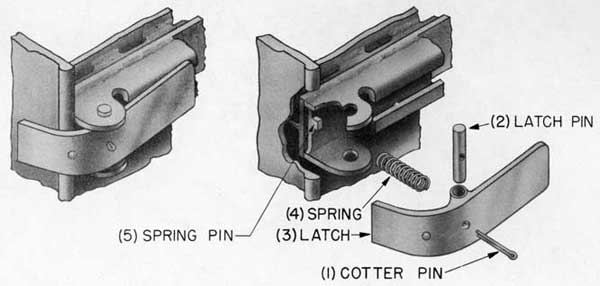
INTERLOCK LATCH, SLIDING DOG AND ROTATING DOG LEVER TYPE DOORS (Fig. 34)
The interlock latch on both lever type doors locks and unlocks the operating mechanism. When the door is open, the dogs are prevented from being moved beyond the edge of the door. When the door is closed, the interlock latch slides on the side of the door frame knife edge, lifts up and unlocks the dogging mechanism.
HOW TO REPLACE INTERLOCK LATCH, SLIDING DOG
AND ROTATING DOG LEVER TYPE DOORS (Fig. 34):
To Replace Bushing:
(1) Remove cotter pin from latch and latch pin.
(2) Remove latch pin.
(3) Lift off interlock latch.
(4) Remove spring.
To Re-assemble:
(4) Replace spring. Hold spring on spring pin (5).
(3) Replace interlock latch (make sure spring pin on latch is seated in spring).
(2) Replace latch pin.
(1) Insert cotter pin through latch and latch pin.
Close door and check for unlocking action.
Open door and check for locking action.
Fig. 34-Interlock latch, assembly and exploded views,
Sliding Dog Lever Type Door.
33
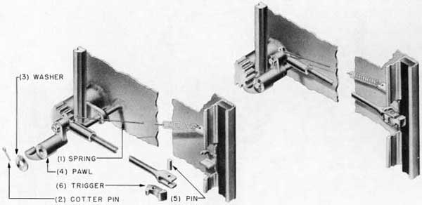
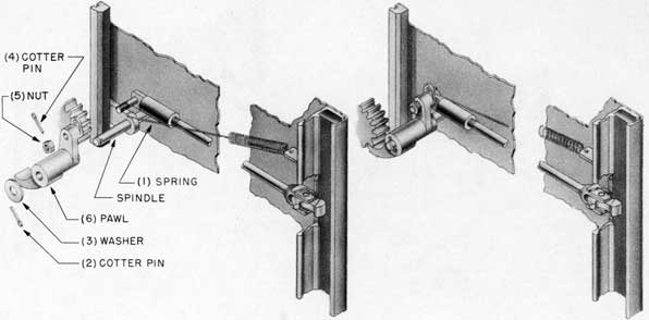
SECTION 23 INTERLOCK TRIGGER REPLACEMENT
The interlock trigger on the Rotating Dog Rack and Pinion Type Door moves the interlock rod that drops the interlock pawl in and out of the pinion teeth. When the door is closed, the trigger moves on the side of knife edge, pushing the interlock rod in, rotating the pawl on its axis and pulling the pawl out of the teeth of the pinion, unlocking the dogging mechanism.
HOW TO REPLACE INTERLOCK TRIGGER, ROTATING DOG RACK AND PINION TYPE DOOR (Fig. 35):
To Dis-assemble:
(1) Unhook spring from pawl.
(2) Remove cotter pin from pawl spindle.
(3) Remove washer from pawl spindle.
(4) Slide pawl off spindle and pull out entire interlock assembly.
(5) Drive out trigger pin.
(6) Remove trigger.
To Re-assemble:
(6) Hold new trigger in place.
(5) Insert trigger pin and drive home.
(4) Slide entire interlock assembly in place and slide pawl on pawl spindle.
(3) Replace washer on pawl spindle.
(2) Insert cotter pin in pawl spindle.
(1) Hook spring to pawl.
Open and close door to test for locking and unlocking action.
Fig. 35-Interlock trigger, assembly and exploded views,
Rotating Dog Rack and Pinion Type Door.
34
SECTION 24 INTERLOCK PAWL REPLACEMENT
The pawl is the hook, on the Rack and Pinion Type Door, that drops into the teeth of the pinion when the door is open, preventing the dogs from being turned beyond the edge of the door.
HOW TO REPLACE PAWL, ROTATING DOG RACK AND PINION TYPE DOOR (Fig. 36):
(6) Slide new pawl on spindle.
(5) Replace nut.
(4) Insert cotter pin.
(3) Replace washer.
(2) Replace cotter pin.
(1) Hook spring to pawl.
Test for positive locking.
Fig. 36-Pawl, Rotating Dog Rack and Pinion Type Door.
35
SECTION 25 PINION REPLACEMENT
The inside and outside handwheel pinions, on the Rack and Pinion Type Door, are both geared to the rack. Turning either handwheel moves the rack up and down, actuating the linkage system. This gearing system reduces the power necessary to operate this type of door.
HOW TO REPLACE OUTSIDE HANDWHEEL PINION, RACK AND PINION TYPE DOOR (Fig. 37):
To Dis-assemble:
From outer side of door:
(1) Remove packing plunger.
(2) Remove two nuts from pinion shaft.
(3) Remove washer from pinion shaft.
(4) Slide outside handwheel off pinion shaft.
(5) Remove bushing, renew if necessary.
From inner side of door.
(6) Remove pinion.
(7) Remove bushings, renew if necessary.
To Re-assemble:
From inner side of door:
(7) Replace bushings.
(6) Replace new pinion.
From outer side of door:
(5) Replace bushing.
(4) Slide outside handwheel on pinion shaft.
(3) Replace washer on pinion shaft.
(2) Replace two nuts, pull tight.
(1) Renew packing and replace packing plunger, see Fig. 14, page 12.
Grease pinion teeth with rust-inhibitive grease.
Test for smooth operation.
Fig. 37-Outside handwheel pinion, assembly and exploded views,
Rack and Pinion Type Door.
36
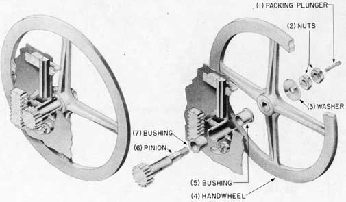
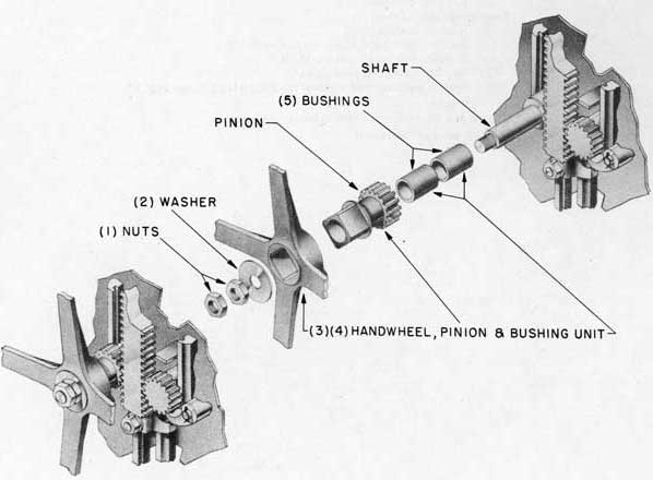
HOW TO REPLACE INSIDE HANDWHEEL PINION, RACK AND PINION TYPE DOOR (Fig. 38):
To Dis-assemble:
(1) Remove two nuts from handwheel shaft.
(2) Remove washer from handwheel shaft.
(3) Slide from shaft, handwheel, pinion and bushing unit.
(4) Remove pinion and bushing unit.
(5) Remove bushings, renew if necessary.
To Re-assemble:
(5) Insert bushings in new pinion.
(4) Insert pinion and bushing unit in handwheel.
(3) Slide handwheel, pinion and bushing unit on handwheel shaft.
(2) Replace washer on handwheel shaft.
(1) Replace two nuts on handwheel shaft, pull tight.
Grease teeth of pinion with rust-inhibitive grease.
Test for smooth operation.
Fig. 38-Inside handwheel pinion, assembly and exploded views,
Rack and Pinion Type Door.
37
SECTION 26 SPARE PARTS
Failure of door parts through normal wear, injury, corrosion and battle damage make it necessary to replace parts at sea. At times it may even be necessary to fabricate a part aboard ship. To meet such an emergency, specifications and heat treatment of parts are covered in Section 26 and detailed drawing numbers are given in the Spare Parts Lists in this section.
If parts are not available and must be ordered from the manufacturer, the name and type of ship and the number of the door opening will facilitate the order as all door openings and their doors are on file with the manufacturer.
SECTION 27 SPARE PARTS LIST
SLIDING DOG LEVER TYPE DOOR. SPARE PARTS ALPHABETICALLY ARRANGED
DESCRIPTION
MFGR'S. PART NO.
MATERIAL (See Section 29)
SPECS.
Connecting rod
connecting rod
59543-G
M.S.
46S1
connecting rod
65740-G
Cold rolled steel
Rockwell B-80
connecting rod
59544-G
M.S.
46S1
connecting rod
59545-G
M.S.
46S1
connecting rod
59546-G
M.S.
46S1
connecting rod
59547-G
M.S.
46S1
connecting rod
59548-G
M.S.
46S1
connecting rod
70357-G
M.S.
46S1
connecting rod
59551-G
M.S.
46S1
connecting rod
59552-G
M.S.
46S1
connecting rod bushing
65361
Super-oilite bearing
connecting rod cotter pin
59914
Everdur
Comm.
connecting rod washer
54282
Stl. SH
Comm.
Dog
dog bracket
57284
M.S. Forging
46S1
dog bracket slide plate
C-58581
Mueller #600
dog compression spring
C-58502
COMP.Pr.
22W5
dog end
C-72901
C.R.S. 1A
46S18
dog operating crank-R.H
58968
HYT Br. Class B
46B29
dog operating crank-L.H.
58969
HYT Br. Class B
46B29
dog operating crank cap-R.H.
58964
Y Brass
Comm.
dog operating crank cap-L.H.
58965
Y Brass
Comm.
dog pivot pin
58962
.13CH.S.Stl.
dog set screw
59963
Stl. SH
Comm.
dog set screw lock screw
58511
Stl. SH
Comm.
dog slider bar-side 18"
58582
C.D.Stl. EG
46S13
dog slider bar-side 20"
58598
C.D.Stl. EG
46S13
dog slider bar-side 21"
58583
C.D.Stl. EG
46S13
dog slider bar-side 22"
58584
C.D.Stl. EG
46S13
dog slider bar-side 24"
58585
C.D.Stl. EG
46S13
dog slider bar-side 26"
58586
C.D.Stl. EG
46S13
dog slider bar-side 30"
58519
C.D.Stl. EG
46S13
dog slider bar-side 36"
58587
C.D.Stl. EG
46S13
dog slider bar-side 42"
58588
C.D.Stl. EG
46S13
dog slider bar-side 42 spec.
58518
C.D.Stl. EG
46S13
38
SLIDING DOG LEVER TYPE DOOR, SPARE PARTS ALPHABETICALLY ARRANGED-(Continued)
DESCRIPTION
MFGR'S. PART NO.
MATERIAL (See Section 29)
SPECS.
dog slider bar-end 6" R.H.
60142
C.D.Stl. EG
46S13
dog slider bar-end 6" L.H
60143
C.D.Stl. EG
46S13
dog slider bar-end 8" R.H.
60140
C.D.Stl. EG
46S13
dog slider bar-end 8" L.H.
60141
C.D.Stl. EG
46S13
dog slider bar-end 10"
70353
C.D.Stl. EG
46S13
dog slider bar-end 15"
65739
C.D.Stl. EG
46S13
dog spindle bushing
65362
Super-oilite bearing
dog spindle nut
52743
Stl. EG
SAE-1112
dog spindle nut pin
58523
Stl. EG
42P6
dog wedge nut pin
C-58580
Bronze
46B28
Gasket
gasket, rubber
D-32666
Rubber
Comm.
Hand lever
hand lever assembly 12"
46454
M.S.Galv.
46S1
hand lever assembly 15"
39000
M.S.Galv.
46S1
hand lever assembly 18"
49506
M.S.Galv.
46S1
hand lever shaft
E-54250
M.S.SH Ass'y.
46S1
hand lever shaft bushing
64912
Super-oilite bearing
hand lever shaft link
C-54249
M.S.SH Ass'y.
46S1
hand lever shaft nut
61703
C.D.Stl.
SAE-X1020
hand lever shaft plunger
52742
Stl. EG
SAE 1040-45
hand lever shaft sleeve
58506
Seamless steel Tubing
44T1
hand lever shaft sleeve rein
58148
M.S.
48S5
Hinge
hinge pin
C-39127
COMP. Nr.
46B6
hinge pin collar
C-39128
COMP. Nr.
46B6
hinge washer
47482
Comm.Brass
Comm.
Interlock
interlock latch
58575
Flange SH Ass'y.
48S5
interlock latch cotter
59914
Everdur
Comm.
interlock latch pin
58514
M.S. EG
46S1
interlock latch spring
C-38921
COMP. Pr.
22W5
interlock latch spring pin
58515
M.S.SH Ass'y.
46S1
interlock rod-18"
58589
M.S.SH Ass'y.
46S1
interlock rod-21"
58590
M.S.SH Ass'y.
46S1
interlock rod-22"
58591
M.S.SH Ass'y.
46S1
interlock rod-24"
58592
M.S.SH Ass'y.
46S1
interlock rod-26"
58593
M.S.SH Ass'y.
46S1
interlock rod-30"
58594
M.S.SH Ass'y.
46S1
interlock rod-36"
58595
M.S.SH Ass'y.
46S1
interlock rod-42"
58596
M.S.SH Ass'y.
46S1
interlock rod slide button
58512
M.S.SH Ass'y.
46S1
interlock rod stud
58513
M.S.SH Ass'y.
46S1
interlock rod stud cotter
59914
M.S.SH Ass'y.
46S1
Toggle arm
toggle arm-R.H
65628
COMP. MnC
49B3
toggle arm-L.H
65629
COMP. MnC
49B3
toggle arm bushing
64908
Super-oilite bearing
toggle arm lock pin
54274
Stl. EG
46S1
toggle arm pin
58503
M.S. SH
46S1
toggle arm spring main leaf
C-58507
COMP.Pr.S.T.
46B14
toggle arm spring 2nd leaf
C-58508
COMP.Pr.S.T.
46B14
toggle arm spring 3rd leaf
C-58509
COMP.Pr.S.T.
46B14
toggle arm spring BK plate
58577
M.S.EG
48S5
toggle arm spring bolt
58121
Stl. EG
SAE-1112
toggle arm spring lock washer
C-61045
Soft brass
Comm.
NOTE: Reference Drawings, Sliding Dog Lever Type Door.
TITLE
HEINTZ NO.
TITLE
HEINTZ NO.
Plans
T-79718
Sections
T-79719
Door Schedule
E-79715
Details
T-79720
39
SLIDING DOG LEVER TYPE DOOR, SPARE PARTS NUMERICALLY ARRANGED
MFGR'S PART NUMBER
DESCRIPTION
D-32666
Gasket, rubber
C-38921
Interlock latch spring
39000
Hand lever assembly, 15"
C-39127
Hinge pin
C-39128
Hinge pin collar
46454
Hand lever assembly, 12"
47482
Hinge washer
49506
Hand lever assembly, 18"
52742
Hand lever shaft plunger
52743
Dog spindle nut
C-54249
Hand lever shaft link
E-54250
Hand lever shaft
54274
Toggle arm lock pin
54282
Connecting rod washer
57284
Dog
58121
Toggle arm spring bolt
58148
Hand lever shaft sleeve rein
C-58502
Dog compression spring
58503
Toggle arm pin
58506
Hand lever shaft sleeve
C-58507
Toggle arm spring, main leaf
C-58508
Toggle arm spring, 2nd leaf
C-58509
Toggle arm spring, 3rd leaf
58511
Dog set screw lock screw
58512
Interlock rod slide button
58513
Interlock rod stud
58514
Interlock latch cotter
58515
Interlock latch spring pin
58518
Dog slider bar, side, 42" special
58519
Dog slider bar, side, 30"
58523
Dog spindle nut pin
58575
Interlock latch
58577
Toggle arm spring back plate
C-58580
Dog wedge
C-58581
Dog Brack slide plate
58582
Dog slider bar, side, 18"
58583
Dog slider bar, side, 21"
58584
Dog slider bar, side, 22"
58585
Dog slider bar, side, 24"
58586
Dog slider bar, side, 26"
58587
Dog slider bar, side, 36"
58588
Dog slider bar, side, 42"
MFGR'S PART NUMBER
DESCRIPTION
58589
Interlock rod 18"
58590
Interlock rod 21"
58591
Interlock rod 22"
58592
Interlock rod 24"
58593
Interlock rod 26"
58594
Interlock rod 30"
58595
Interlock rod 36"
58596
Interlock rod 42"
58598
Dog slider bar, side, 20"
58962
Dog pivot pin
58964
Dog operating crank cap, right hand
58965
Dog operating crank cap, left hand
58968
Dog operating crank, right hand
58969
Dog operating crank, left hand
59543-G
Connecting rod
59544-G
Connecting rod
59545-G
Connecting rod
59546-G
Connecting rod
59547-G
Connecting rod
59548-G
Connecting rod
59551-G
Connecting rod
59552-G
Connecting rod
59914
Connecting rod cotter pin and interlock rod stud cotter pin
59963
Dog set screw
60140
Dog slider bar-end, 8" right hand
60141
Dog slider bar-end, 8" left hand
60142
Dog slider bar-end, 6" right hand
60143
Dog slider bar-end, 6" left hand
C-61045
Toggle arm spring lock washer
61703
Hand lever shaft nut
64908
Toggle arm bushing
64912
Hand lever shaft bushing
65361
Connecting rod bushing
65362
Dog spindle bushing
65628
Toggle arm, right hand
65629
Toggle arm, left hand
65739
Dog slider bar-end 15"
65740-G
Connecting rod
70353
Dog slider bar-end 10"
70357-G
Connecting rod
C-72901
Dog end
40
ROTATING DOG LEVER TYPE DOOR, SPARE PARTS ALPHABETICALLY ARRANGED
DESCRIPTION
MFGR'S. PART NO.
MATERIAL (See Section 29)
SPECS.
Connecting link
connecting link R.H. 26"
38450
M.S. Galv.
46S1
connecting link L.H. 26"
38451
M.S. Galv.
46S1
connecting link R.H. 30"
47478
M.S. Galv.
46S1
connecting link L.H. 30"
47479
M.S. Galv.
46S1
connecting link R.H. 36"
46242
M.S. Galv.
46S1
connecting link L.H. 36"
46241
M.S. Galv.
46S1
connecting link R.H. 24"
58878
M.S. Galv.
46S1
connecting link L.H. 24"
58879
M.S. Galv.
46S1
connecting link bushing
64910
Super-oilite bearing
connecting link plate 36" and 42"
46243
M.S. Galv.
46S1
connecting link plate 24" to 30"
38452
M.S. Galv.
46S1
connecting link stud
63122
MED.STL.SHER
46S1
connecting link washer
54284
Stl. SH
Comm.
Connecting rod
connecting rod
58958
M.S. Galv.
46S1
connecting rod
54360
M.S. Galv.
46S1
connecting rod
54362
M.S. Galv.
46S1
connecting rod
55920
M.S. Galv.
46S1
connecting rod
56710
M.S. Galv.
46S1
connecting rod
58960
M.S. Galv.
46S1
connecting rod
54361
M.S. Galv.
46S1
connecting rod
54363
M.S. Galv.
46S1
connecting rod
55921
M.S. Galv.
46S1
connecting rod
56711
M.S. Galv.
46S1
connecting rod
57666
M.S. Galv.
46S1
connecting rod stud
63125
M.S. Galv.
46S1
connecting rod stud bushing
64909
Super-oilite bearing
connecting rod stud collar
C-63120
Stl. SH
SAE-1112
connecting rod stud pin
53737
Stl. Galv.
Comm.
connecting rod stud washer
54353
Stl. SH
Comm.
Dog, rotating
dog, rotating-R.H.
E-46866A
M.S. Forg.
46S1
dog, rotating-R.H
32504A
M.S. Forg.
46S1
dog, rotating-R.H.
E-32508A
M.S. Forg.
46S1
dog, rotating-L.H.
E-32501A
M.S. Forg.
46S1
dog, rotating-L.H.
32505A
M.S. Forg.
46S1
dog, rotating-L.H.
E-46865A
M.S. Forg.
46S1
dog, rotating and bell crank-R.H.
32502A
M.S. Forg.
46S1
dog, rotating and bell crank-R.H
32506A
M.S. Forg.
46S1
dog, rotating and bell crank-L.H
32503A
M.S. Forg.
46S1
dog, rotating and bell crank-L.H.
32507A
M.S. Forg.
46S1
dog, rotating bushing
64913
Super-oilite bearing
dog, rotating crank bushing
64909
Super-oilite bearing
dog, rotating lock screw
C-55164
C.R.S. Class #6 Type A
46S18
dog, rotating nut
C-54233
Stl. EG
SAE-1112
dog, rotating nut pin
54271
Stl. EG
42P6
dog, rotating roller
C-54248
Stl. SH
SAE-1050
dog, rotating roller bushing
64908
Super-oilite bearing
dog, rotating roller nut
C-54232
Stl. EG
SAE-1112
dog, rotating roller nut pin
54291
Stl. EG
42P6
dog, rotating roller washer
54281
Stl. SH
Comm.
dog, rotating spindle
C-54247
Stl. SH
SAE-1040
heat treated
dog, rotating spindle sleeve
56220
Steel
SAE-1015
dog, rotating wedge-R.H.
52410-B
CU.SI.ALLOY Casting
46B28
dog, rotating wedge-L.H.
52411-B
CU.SI.ALLOY Casting
46B28
Gasket, rubber 1/2" x 1 1/4"
D-32666
Rubber
Comm.
Hand lever assembly
hand lever assembly 15"
39000
M.S. Galv.
46S1
hand lever assembly 18"
49506
M.S. Galv.
46S1
hand lever shaft
E-54250
M.S.
46S1
41
ROTATING DOG LEVER TYPE DOOR, SPARE PARTS ALPHABETICALLY ARRANGED-(Continued)
DESCRIPTION
MFGR'S. PART NO.
MATERIALS (See Section 29)
SPECS.
hand lever shaft bushing
64902
Super-oilite bearing
hand lever shaft link
C-54249
Med. Steel
46S1
hand lever shaft nut
61703
Steel El. Galv.
46S1
hand lever shaft plunger
52742
Stl. EG
SAE-1040-45
hand lever shaft sleeve
38465
M.S.
46S13
Hinge
hinge adjusting yoke
75736
Flange Stl.
48S5
hinge adjusting yoke hex. nut
60449
Comm. brass
Comm.
hinge adjusting yoke pin
C-75738
COMP. Nr.
46B6
hinge adjusting yoke set screw
75747
Stl. SH
hinge collar
32157
COMP. Nr.
46B6
hinge cotter pin 5/32" x 2"
78211
C.R.S.
Comm.
hinge pin
C-75737
COMP. Nr.
46B6
hinge washer
75748
Comm. brass
Comm.
hinge washer
20896
Comm. brass
Comm.
hinge washer
76568
Comm. brass
Comm.
Interlock
interlock cotter pin 3/32" x 1 1/8"
59342
Stl. EG
Comm.
interlock trip
59337
M.S.
48S5
interlock trip pin
59338
Stl. EG
46S1
interlock trip pin sleeve
C-59341
Steel
44P10
interlock trip spring
C-24414
COMP.Pr.S.T.
22W5
interlock trip spring pin
59339
M.S.
46S1
interlock trip stop plate
C-68800
M.S.
48S5
interlock trip stop plate rivet
68116
Steel
Comm.
Link
link bell crank to dog
43025
M.S. Galv.
46S1
link bell crank to dog
50292
M.S. Galv.
46S1
link bell crank to dog
52289
M.S. Galv.
46S1
link bell crank to dog, bushing
64921
Super-oilite bearing
link bell crank to dog, washer
54283
Stl. SH
Comm.
Name plate (outside)
name plate (outside)-off
C-39006
Zinc Sheet
name plate (outside)-on
C-39007
Zinc Sheet
name plate (outside) drive screw
C-60882
Hardened steel Brass plated
Stop pin
stop pin mach. screw (12-24 x 5/8")
64918
Stl. EG
Comm.
stop pin spring
C-38880
COMP. Pr.S.T.
46B14
stop pin spring backing plate
C-38881
COMP. Pr.S.T.
46B14
stop pin spring backing plate
C-38882
COMP.Pr.S.T.
46B14
stop pin spring tapping plate
C-64924
Stl. EG
48S5
Toggle arm
toggle arm-R.H. 24" to 36"
38462
COMP. MnC
49B3
toggle arm-L.H. 24" to 36"
38463
COMP. MnC
49B3
toggle arm-R.H. 42"
49562
COMP. MnC
49B3
toggle arm-L.H. 42"
49563
COMP. MnC
49B3
toggle arm bushing
64907
Super-oilite bearing
toggle arm clevis pin
C-64915
Stl. SH
SAE-1112
toggle arm locking pin 1/8" x 7/8"
54273
Stl. EG
46S1
toggle arm locking pin 1/8" x 1 1/2"
54274
Stl. EG
46S1
toggle arm pin
54251
M.S.
46S1
toggle arm roller
C-64916
HYT Bronze
Grade #2
toggle arm roller cam 24" to 26"
38468
C.R.S. 1A
46S18
toggle arm roller cam 30" to 36"
C-46195
C.R.S. 1A
46S18
toggle arm roller cam 42"
C-49561
C.R.S. 1A
46S18
toggle arm roller pin
C-64914
M.S.
46S1
NOTE: Reference Drawings Rotating Dog Lever Type Door.
TITLE
HEINTZ NO.
TITLE
HEINTZ NO.
Plans
T-78267
Details
T-78269
Door Schedule
E-78154
Sections & Details
T-78260
Sections
T-78268
42
ROTATING DOG LEVER TYPE DOOR, SPARE PARTS NUMERICALLY ARRANGED
MFGR'S PART NUMBER
DESCRIPTION
20896
Hinge washer
C-24414
Interlock trip spring
32157
Hinge collar
E-32501A
Dog, rotating left hand
32502A
Dog, rotating & bell crank, right hand
32503A
Dog, rotating & bell crank, left hand
32504A
Rotating dog, right hand
32505A
Rotating dog, left hand
32506A
Rotating dog & bell crank, right hand
32507A
Rotating dog & bell crank, left hand
E-32508A
Rotating dog, right hand
D-32666
Gasket, rubber, 1/2" x 1 1/4"
38450
Connecting link, right hand 26"
38451
Connecting link, left hand 26"
38452
Connecting link, plate 24" to 30"
38462
Toggle arm, R. H. 24" to 36"
38463
Toggle arm, L. H. 24" to 36"
38465
Hand lever shaft sleeve
38468
Toggle arm roller cam 24" to 26"
C-38880
Stop pin spring
C-38881
Stop pin spring becking plate
C-38882
Stop pin spring becking plate
39000
Hand lever assembly
C-39006
Name plate (outside)-OFF
C-39007
Name plate (outside)-ON
43025
Link, bell crank to dog
C-46195
Toggle arm roller cam 30" to 36"
46241
Connecting link, L. H. 36"
46242
Connecting link, R. H. 36"
46243
Connecting link plate 36" & 42"
E-46865A
Dog, rotating, L. H.
E-46866A
Dog, rotating, R. H.
47478
Connecting link, R. H. 30"
47479
Connecting link, L. H. 30"
49506
Hand lever assembly 18"
C-49561
Toggle arm roller cam 42"
49562
Toggle arm R. H. 42"
49563
Toggle arm L. H. 42"
50292
Link bell crank to dog
52289
Link bell crank to dog
52410-B
Dog, rotating wedge, R. H.
52411-B
Dog, rotating wedge, L. H.
52742
Hand lever shaft plunger
53737
Connecting rod stud pin
C-54232
Dog, rotation nut
C-54233
Dog, rotation nut
C-54247
Dog, rotation spindle
C-54248
Dog, rotating roller
C-54249
Hand lever shaft link
E-54250
Hand lever shaft
54251
Toggle arm pin
MFGR'S PART NUMBER
DESCRIPTION
54271
Dog, rotating nut pin
54273
Toggle arm locking pin 1/8" x 7/8"
54274
Toggle arm locking pin 1/8" x 1 1/2"
54281
Dog, rotating roller washer
54283
Link bell crank to dog, washer
54284
Connecting link washer
54291
Dog, rotation roller nut pin
54353
Dog, rotation stud washer
54360
Connecting rod
54361
Connecting rod
54362
Connecting rod
54363
Connecting rod
C-55184
Dog, rotating lockscrew
55920
Connecting rod
55921
Connecting rod
56220
Dog rotating spindle sleeve
56710
Connecting rod
56711
Connecting rod
57666
Connecting rod
58878
Connecting link, R. H. 24"
58879
Connecting link, L. H. 24"
58958
Connecting rod
58960
Connecting rod
59337
Interlock trip
59338
Interlock trip pin
59339
Interlock trip spring pin
C-59341
Interlock trip pin sleeve
59342
Interlock cotter pin 3/32" x 1 1/8"
60449
Hinge adjusting hex. nut
C-60882
Name plate (outside) drive screw
61703
Hand lever shaft nut
C-63120
Connecting rod stud collar
63122
Connecting link stud
63125
Connecting rod stud
64907
Toggle arm bushing
64908
Dog, rotating roller bushing
64909
Connecting rod stud bushing, and dog rotating crank bushing
64910
Connecting link bushing
64912
Hand lever shaft bushing
64913
Dog, rotating bushing
C-64914
Toggle arm roller pin
C-64915
Toggle arm clevis pin
C-64916
Toggle arm roller
64918
Stop pin mach. screw (12-24 x 5/8")
64921
Link bell crank to dog bushing
C-64924
Stop pin spring topping plate
68116
Interlock trip stop plate rivet
C-68800
Interlock trip stop plate
75736
Hinge adjusting yoke
C-75737
Hinge pin
G-75738
Hinge adjusting pin
75747
Hinge adjusting yoke set screw
75748
Hinge washer
76568
Hinge washer
78211
Hinge cotter pin, 5/32" x 2" long
43
ROTATING DOG RACK AND PINION TYPE DOOR, SPARE PARTS ALPHABETICALLY ARRANGED
DESCRIPTION
MFGR'S. PART NO.
MATERIALS (See Section 29)
SPECS.
Connecting rod
connecting rod-bottom
E-46255
Alum. alloy
46A10
connecting rod-sides
46280
Alum. alloy
46A10
connecting rod-top
46245
Alum. alloy
46A10
connecting rod stud
36214
C.R.S. 7A
46S18
connecting rod stud
C-34941
C.R.S. 7A
46S18
connecting rod stud collar
C-36213
COMP. Nr.
46B6
connecting rod stud cotter pin
C-25126
Brass
Comm.
connecting rod stud washer
C-34942
C.R.S. #1
47S20
Dog, rotating
dog, rotating
E-32501
Bronze Forg.
See note A, page 49
dog, rotating
E-32508
Bronze Forg.
See note A, page 49
dog, rotating-R.H
E-32504
Bronze Forg.
See note A, page 49
dog, rotating-L.H.
E-32505
Bronze Forg.
See note A, page 49
dog, rotating & bell crank-R.H.
E-32 502
Bronze Forg.
See note A, page 49
dog, rotating & bell crank-R.H
E-32506
Bronze Forg.
See note A, page 49
dog, rotating & bell crank-L.H.
E-32503
Bronze Forg.
See note A, page 49
dog, rotating & bell crank-L.H.
E-32507
Bronze Forg.
See note A, page 49
dog, rotating bushing
C-36218
Bronze
See note B, page 49
dog, rotating crank bushing
29720
Bronze
See note B, page 49
dog, rotating lock screw
C-36205
C.R.S. 7A
46S18
dog, rotating nut
C-32517
COMP. Nr.
46B6
dog, rotating nut pin
C-32515
C.R.S. 1A
46S18
dog, rotating roller
C-36204
Mueller #600
Rockwell-B-95
Bearing Metal
dog, rotating roller bushing
31143
Bronze
See note B, page 49
dog, rotating roller washer
31152
COMP. Nr.
46B6
dog, rotating roller nut
C-32509
COMP. Nr.
46B6
dog, rotating roller nut pin
C-32510
C.R.S. 1A
46S18
dog, rotating spindle
C-36202
C.R.S. 7A
46S18
dog, rotating wedge-R.H
E-36200
C.R.S. 1A
46S18
dog, rotating wedge-L.H
E-36201
C.R.S. 1A
46S18
Gasket, rubber IA" x 1%"
D-32666
Rubber
Comm.
Handwheel
handwheel-inside
29953
Alum. alloy class 5
46A1
handwheel-outside
29954
Alum. alloy class 5
46A1
handwheel bushing-inside
31143
Bronze
See note B, page 49
handwheel bushing-outside
C-29766
C.R.S. 7A
46S18
handwheel pinion-inside
E-36216
C.R.S. 7A
46S18
handwheel pinion-outside
E-32524
COMP. Mn-r
46B15
handwheel pinion bushing-inside
36215
Bronze
See note B, page 49
handwheel pinion bushing-outside
C-36218
Bronze
See note B, page 49
handwheel pinion sleeve-inside
C-34947
M.S.
46S1
handwheel pinion sleeve-outside
C-32522
Steel tub Type #1
44T1
handwheel spindle-inside
C-34948
C.R.S. 7A
46S18
handwheel spindle nut
35292
COMP. Nr.
46B6
handwheel spindle washer-inside
C-29955
C.R.S. #1
47S20
handwheel spindle washer-inside
C-36219
Felt
Comm.
handwheel spindle washer-inside
C-29724A
COMP. Nr.
46B6
handwheel spindle washer-outside
C-29956
C.R.S. #1
47S20
handwheel spindle taper pin
C-32098
C.R.S. 1A
46S18
handwheel spindle plunger
C-19123
COMP. Pr.
46B3
44
ROTATING DOG RACK AND PINION TYPE DOOR, SPARE PARTS ALPHABETICALLY ARRANGED
(Continued)
DESCRIPTION
MFGR'S. PART NO.
MATERIALS (See Section 29)
SPECS.
Hinge
hinge pin
40023
COMP. Nr.
46B6
hinge pin
40024
C.R.S. 1A
46S18
hinge pin collar
32157
COMP. Nr.
46B6
hinge pin collar
35472
C.R.S. 1A
46S18
hinge washer
C-34319
COMP. Nr.
46B6
Interlock
interlock bolt
C-29944
C.R.S. 7A
46S18
interlock bolt nut
C-31238
COMP. Nr.
46B6
interlock cotter pin
C-30062
Brass
Comm.
interlock pawl-R.H.
E-30064
COMP. MnC
49B3
interlock pawl-L.H.
E-30065
COMP. MnC
49B3
interlock pawl washer
30063
COMP. Nr.
46B6
interlock pin
C-32542
interlock rod assembly
45931
M.S. Galv.
46S1
interlock rod adj. end
C-30998
COMP. Nr.
46B6
interlock spring
46256
Phos. Bronze
22W5
interlock trigger
C-31003
Bronze Forg.
See note A, page 49
Light, fixed
light, fixed gasket-outside
C-32689
Rubber
Comm.
light, fixed gasket-inside
C-36280
light, fixed lens
C-37337
light, fixed lockwasher
C-34116
light, fixed nut
C-31238
COMP. Nr.
46B6
light, fixed retainer
E-35713
M.S.
48S5
Link
link bell crank to bell crank
46293
M.S. Galv.
46S1
link bell crank to bell rack
46294
link bushing-plain
24505
Bronze
See note B, page 49
link bushing-shoulder
C-34944
link washer
29723
COMP. Nr.
46B6
Rack
rack
D-32818-A
COMP. MnC
49B3
rack roller
C-32530
Mueller #600
Rockwell-B-95
Bearing Metal
rack roller bushing
C-32531
Bronze
See note B, page 49
rack roller bolt-bottom
C-32532
C.R.S. 7A
46S18
rack roller bolt-top
C-32533
C.R.S. 7A
46S18
rack roller pin, bolt-bottom
C-31639
C.R.S. 1A
46S18
rack roller pin, bolt-top
C-31140
C.R.S. 1A
46S18
rack roller bolt nut
C-31151
COMP. Nr.
46B6
rack spring clip
C-31634
COMP. Pr.
46B14
rack stud, conn. rod
36220
C.R.S. 7A
46S18
NOTE: Drawings Covering the Rotating Dog Rack and Pinion Type Door.
TITLE
HEINTZ NO.
TITLE
HEINTZ NO.
Plans
T-48382
Sections
T-48383
Door Schedule
T-48370
Details
T-48384
45
ROTATING DOG RACK AND PINION TYPE DOOR, SPARE PARTS NUMERICALLY ARRANGED
MFGR'S PART NUMBER
DESCRIPTION
C-19123
Handwheel spindle plunger
24505
Link bushing, plain
C-25126
Connecting rod stud cotter pin
29720
Dog, rotating, crank bushing
29723
Link washer
C-29724A
Handwheel spindle washer, inside
C-29766
Handwheel bushing, outside
C-29944
Interlock bolt
29953
Handwheel, inside
29954
Handwheel, outside
C-29955
Handwheel spindle washer, inside
C-29956
Handwheel spindle washer, outside
C-30062
Interlock cotter pin
30063
Interlock pawl washer
E-30064
Interlock pawl, right hand
E-30065
Interlock pawl, left hand
C-30998
Interlock rod adjustable end
C-31003
Interlock trigger
C-31140
Rack roller bolt, pin top
31143
Dog, rotating, roller bushing and handwheel bushing, inside
G-31151
Rack roller bolt nut
31152
Dog, rotating, roller washer
C-31238
Interlock bolt nut
C-31634
Rack spring clip
C-31639
Rack roller bolt pin, bottom
C-32098
Handwheel spindle taper pin
32157
Hinge pin collar
E-32501
Dog, rotating
E-32502
Dog, rotating, and bell crank, 90°, right hand
E-32503
Dog, rotating, and bell crank, 90°, left hand
E-32504
Dog, rotating, right hand
E-32505
Dog, rotating, left hand
E-32506
Dog, rotating, and bell crank, 180°, right hand
E-32507
Dog, rotating, and bell crank 180°, left hand
E-32508
Dog, rotating
C-32509
Dog, rotating, roller nut
C-32510
Dog, rotating, roller nut pin
MFGR'S PART NUMBER
DESCRIPTION
C-32515
Dog, rotating, nut pin
C-32517
Dog, rotating, nut
C-32522
Handwheel pinion sleeve, outside
E-32524
Handwheel pinion, outside
C-32530
Rack roller
C-32531
Rack roller bushing
C-32532
Rack roller bolt, bottom
C-32533
Rack roller bolt, top
C-32542
Interlock pin
D-32666
Gasket, rubber, 1/2" x 1 1/4"
D-32818-A
Rack
C-34319
Hinge washer
C-34941
Connecting rod stud
C-34942
Connecting rod stud washer
C-34944
Link bushing, shoulder
C-34947
Handwheel pinion sleeve, inside
C-34948
Handwheel spindle inside
35292
Handwheel spindle nut
35472
Hinge pin collar
E-36200
Dog, rotating wedge, right hand
E-36201
Dog, rotating wedge, left hand
C-36202
Dog, rotating, spindle
C-36204
Dog, rotating, roller
C-36205
Dog, rotating, lock screw
C-36213
Connecting rod stud collar
36214
Connecting rod stud
36215
Handwheel pinion bushing, inside
E-36216
Handwheel pinion, inside
36218
Dog, rotating, bushing and handwheel pinion bushing, outside