The procedures outlined below can best be performed if the ship is in a protected harbor.
However, do not attempt replacement at any time without covering the director or indicator to
prevent entry of soot, grit, or moisture. After making replacement, subject installation should
be checked at shore base or tender as soon as possible. Director must he at zero before starting
replacement of electrical equipment and completely tie-energized.
1. Sight Angle Motor (Director Case)
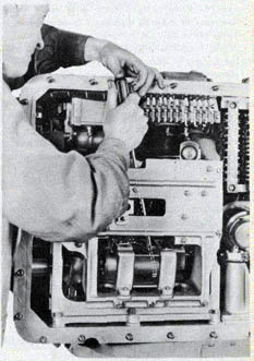
Remove director back cover, see figure 28; remove four screws holding motor to computer back
plate. The two inner screws may be reached with a long shanked screw driver from the upper
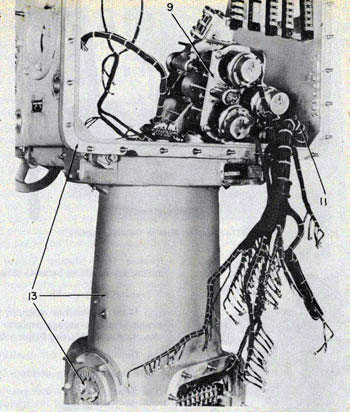
part of the computer. The inner screws can be seen after fuse box cover has been removed and
fuse block dropped. See figure 93. Withdraw motor to rear, disconnect wires from small
terminal block on motor. See figure 94.
If the sight angle replacement motor does not contain a magnetic brake, remove the brake from
original motor and attach to replacement. See figure 34.
Remove gear from shaft on end of motor and install on replacement motor.
Replace new motor in reverse order and check for proper mesh with computer mating gear.
2. Own Ship Course Follow-up Motor (Director Case)
Remove director back cover. Remove covers from own ship course unit. Remove dials of own
ship course unit. Remove dial shield of own ship course unit. Next, loosen five bolts from top of
case and remove four bolts. See figure 108. Disconnect own ship course unit wires from
terminal board. R1F, R2F, V1, V2, U2A, U2B, S1F, S2F, S3F. Refer to BuOrd Dwg
168050. Cut all ties necessary to free these cables.
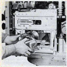
Remove center piece of Oldham coupling which connects own ship course to computer. See figure 95.
Now take a firm grip on the unit and remove fifth bolt. Now remove unit by siding as far as
possible to the right side of the director case and withdraw through rear of case. See figure 112.
Caution. Extreme care must be taken in removing unit so as not to damage computer follow-up
gear and heart-shaped cam assembly.
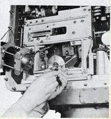
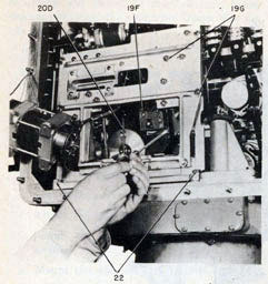
Figure 93-Removing the two inner mounting screws of the director sight angle motors with a long shanked screw driver.
105
TORPEDO FIRE CONTROL EQUIPMENT (DESTROYER TYPE) - OP 1586
Figure 94-Withdrawing director sight angle motor from case in order to disconnect terminal
wires.
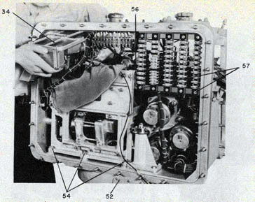
Next, take the unit below decks to the machine shop.
Remove three wires from top of the motor. Withdraw four mounting screws and lift motor and
damper assembly from chassis. See figures 47 and 142.
Remove flywheel damper assembly from motor by loosening clamp nut and sliding off shaft.
Now, remove gear from opposite end of motor shaft.
Install new motor on chassis after attaching gear and flywheel damper.
Complete replacement by performing above steps in reverse order.
3. Own Ship Course Synchro Motor (Director Case)
Repeat all steps outlined in paragraph 2 above for withdrawing unit from case.
Remove wire cover, if necessary. Remove wires.
Remove "U" shaped frame from unit chassis and hexagon post from bearing cap.
Remove heart-shaped cam assembly by loosening clamp and sliding assembly from rotor shaft,
after having first removed pigtail. See figures 44 and 142.
Withdraw four screws securing the motor mounting clamps to chassis.,
Now, lift synchro motor from chassis. See figures 47 and 142. Remove bearing from rear of
synchro motor with bearing puller.
Remove gear from front of synchro motor, use care to prevent damage. Now, remove bearing.
Install new synchro and reassemble in reverse order of outline given above.
Check for electrical zero following procedure outlined in 0P1303. Set the roller in the
heartshaped cam assembly so that zero point of the cam rollers and the synchro coincide.
4. Synchro Generators A, B, C, D, and E in Transmitter (Director Case)
A, B, and E: The removal procedure of these three generators is similar.
Figure 95-Removing center piece of director own ship course unit's Oldham coupling to computer preparatory to replacement of defective electrical part.
106
REPLACEMENT OF ELECTRICAL UNITS
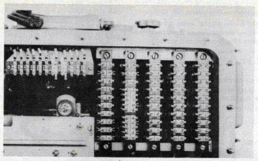
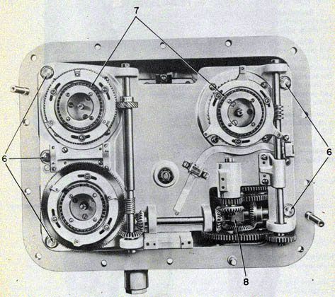
Figure 96-Numbered wiring leads on director terminal boards.
Remove back cover of director, trace wiring from synchro to be removed and disconnect from
terminal board, R1A, R1B, R1E, R2A, R2B, R2E, S1A, S1B, S1E, S2A, S2B, S2E, S3A, S3B, and S3E. See figure 96.
Cut ties on tree and remove synchro wires.
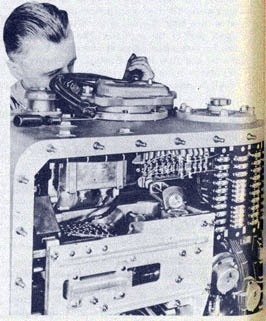
Figure 97-Gyro angle hand crank cover removed from left side of director case so that wiring leads to synchro generators C and D can be disconnected.
Loosen three clamping screws from generator and remove from chassis.
Remove gear from generator shaft.
Install gear on replacement generator.
Now install replacement generator in transmitter in reverse order. Be sure generator gear
meshes correctly with mating gear.
Figure 98-It is necessary to tie the director sight angle motor out of the way before removal of
follow-up switch.
107
TORPEDO FIRE CONTROL EQUIPMENT (DESTROYER TYPE) OP 1586
Check new generators for electrical zero following procedure outlined in OP 1303.
C and D: Remove gyro angle hand crank cover as well as the back cover from the director. See figure 97.
Disconnect terminals S1C, S2C, S3C, R1C, R2C, RID, R2D, S1D, S2D, and S3D. See figure 96.
Cut ties as necessary on tree to free wires.
Remove three clamping screws from generator to be removed. Lift out generator. See figure 51.
Remove gear from end of generator shaft, and reassemble on replacement generator.
Now insert replacement generator and follow above procedure in reverse order. Check gear mesh.
Check replacement generator for electrical zero following procedure outlined in OP 1303.
5. Follow-up Switch (Director Case)
Remove rear cover of director.
Remove sight angle motor following procedure outlined in section 1 of this chapter. Tie motor to
one side. See figure 98.
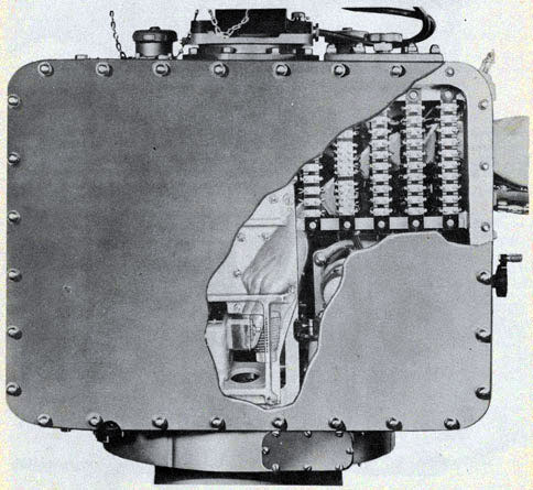
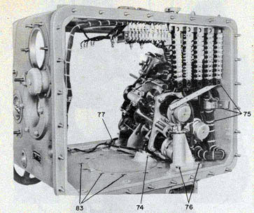
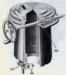
Figure 99.-Phantom view of method to be followed in order to replace defective heating unit in director case.
108
REPLACEMENT OF ELECTRICAL UNITS
Remove three wires from follow-up switch.
Remove three attachment screws.
Remove follow-up switch. See figure 98.
Rotate gear in follow-up switch in counterclockwise direction until points function opposite to
direction of follow-up gear rotation.
Install replacement switch on computer. Keeping points centered.
Complete installation in reverse order outlined above.
Caution. Do not train director off zero while follow-up switch is removed.
Re-zero director as outlined in Installation Checks and Adjustments, page 93 and 94.
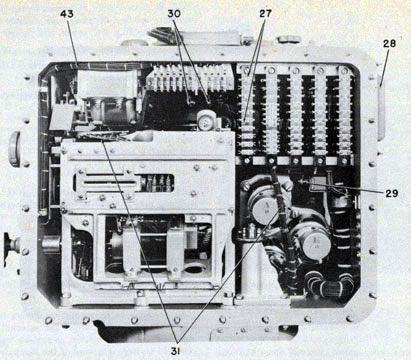
6. Crossline Rheostat (Director Case)
Remove six cap nuts which secure rheostat to top of director case. See figure 27.
Lift out rheostat and disconnect two wire leads.
Replace with new rheostat.
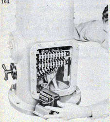
7. Fuses (Director Case)
Loosen four wing nuts on fuse box cover-open box and replace defective fuses. See figure 104.
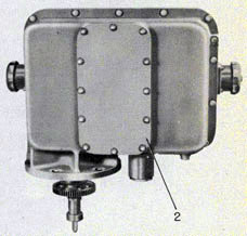
Figure 100-The director stand lower terminal block must be loosened and pushed to one side
before the transformer can be removed.
735193-47-8
8. Heating Unit (Director Case)
Follow procedure outlined in paragraph 7. Remove six bolts holding fuse block.
Reach down through opening to base of case and unscrew defective heating element. See figure 99.
Replace.
9. Capacitor (Director Case)
Remove back cover of director.
Disconnect all capacitor wires.
Remove four screws holding capacitor.
Remove burned out capacitor.
Replace with new capacitor.
10. Terminal Board (Director Case)
Remove rear cover of director. Disconnect wiring from terminal board to be removed. Remove. two holding screws. Lift out board and replace.
11. Lightwells (Director Case)
Remove four screws mounting lightwell to case.
Figure 101-To replace the selector switch, remove the switch handle and cover, disconnect switch from stand, remove lowest terminal block and withdraw switch through terminal block opening.
109
TORPEDO FIRE CONTROL EQUIPMENT (DESTROYER TYPE) OP 1586
Withdraw lightwells from case and disconnect lamp wires.
Replace with new lightwell.
12. Transformer in Director Stand
Remove front and back cover plates from stand. See figure 67.
Remove screws holding the two lower terminal boards on each side of stand.
Remove four bolts holding transformer in. place and disconnect transformer wiring from terminal block.
Lift out transformer. See figure 100.
Install replacement transformer following above procedure in reverse order.
13. Terminal Boards in Director Stand
Disconnect wiring from terminal boards to be removed.
Remove two screws and replace block.
Attach wiring.
14. Transfer Switch in Director Stand
Remove six holding nuts; withdraw transfer switch. Disconnect wiring and replace.
15. Selector Switch in Director Stand
Remove terminal board covers.
Remove screw holding switch handle and cover. See figure 101.
Remove two nuts holding selector switch to stand.
Remove two lower terminal blocks from either side of stand. The wiring, need not be disconnected.
Remove selector switch from inside of stand.
Disconnect all switch wiring.
Install replacement switch in reverse order. See figure 69.
16. Synchro Motors-Torpedo Course Indicator
Remove back and front covers and remove indicator chassis from the case. After disconnecting
wires at terminal board, remove the synchro rotor dials using special tool 8-Z-940. Release
three clamping screws on defective synchro and replace with new synchro after setting on
electrical zero. Refer to figure 74. See OP 1303.
Complete installation in reverse order outlined above.
17. Lightwells-Torpedo Course Indicator
Follow director procedure-see paragraph 11.
18. Terminal Boards-Torpedo Course Indicator
Remove front and back covers and chassis after disconnecting wiring.
Remove terminal board by withdrawing two holding screws.
19. Telescope Lamp on Top of Director Case
Unscrew knurled ring holding socket into lightwell. Withdraw socket and replace lamp.
20. Firing Key in Telescope Bracket
If key becomes defective replace with new key.
110
Chapter 10
DISASSEMBLY. OVERHAUL, ASSEMBLY, AND ADJUSTMENT
In listing the steps to be performed in the disassembly of the fire control system units, the
common causes for mechanical failure are given, but it is impossible to detail here the exact
repairs that are necessary in overhauling the units.
The overhaul of system units is usually performed after a ship's officer has reported the system
is operating improperly and particular units fail to meet the required tests.
After the ship's officer has reported faulty operation, base test crews then examine the system
on the ship, run four problems and if the trouble cannot be corrected, they order the removal of
the faulty unit to the instrument shop for repair. Although the unit is accompanied by an
inspection and test sheet a considerable amount of the operation troubles cannot be found until
certain parts of the interior mechanism are disassembled and thoroughly tested.
Section 1-DISASSEMBLY AND OVERHAUL Torpedo Director
Do not attempt to perform the disassembly by yourself. Two is the minimum number of men
required for the job. No special tools are required.
Note: The removal and replacement of electrical units in the director are outlined in chapter 9.
1. Energize the director.
2. Run four problems, see figures 102 and 103 and record the results on standard test sheet.
3. Make a thorough examination of the exterior of the director. Note condition of lightwell
covers, operation of hand cranks and the condition of glass windows and exposed electrical cable.
Case and Hand Crank. Figures 104 and 105.
4. Remove all hand crank assemblies by removing the screws which attach the hand cranks to the case.
5. Remove the fuse box cover on case by loosening four thumb screws.
6. Drop the fuse block by removing six machine screws.
7. Remove the gyro cover on case withdrawing eight cap nuts.
8. Remove the front cover of the case.
9. Remove the rear cover of the case by loosening and removing 28 acorn nuts.
10. Now test all electrical circuits for continuity and ground. Note all electrical failures. For
replacement of electrical units follow the procedure detailed in chapter 9.
11. At this point de-energize the director before commencing further disassembly.
12. Remove window covers over own ship course dials and sight angle dials. Each cover is held by
six cap nuts.
13. Disconnect all wires to the firing key. Remove the key from the telescope bracket. See
figure 5.
14. Examine the leather diaphragm to see if it is watertight. Check the action of the firing key.
If the operation is impaired, disassemble the key. Inspect the switch of the key for corrosion
and stickiness, clean, or replace parts as necessary.
Telescope. Figures 105 and 107.
15. Remove telescope from director telescope pivot by withdrawing four mounting bolts. See
figure 5. Send the telescope to the optical shop for a complete inspection.
16. Now inspect the interior mechanisms of the director for visual faults such as corrosion,
dirt, fungus, and condition of the insulation on electrical wires.
111
TORPEDO FIRE CONTROL EQUIPMENT (DESTROYER TYPE) OP 1586
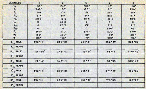
Figure 102-Test problems for port director.
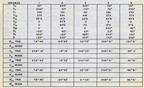
Figure 103-Test problems for starboard director.
112
DISASSEMBLY AND OVERAUL-DIRECTOR
Figure 104-Disassembly of Case and Hand Cranks.
17. Remove eight nuts which secure the telescope pivot to the case.
18. Disconnect wire terminals T1, T2, Y1, Y2, L7 and L17. Cut all ties and remove cable from
harness.
19. Raise edge of telescope pivot at front of director and slide center piece of Oldham coupling
168038-6 out of coupling. This part may be withdrawn through the opening of the fuse box cover.
20. Lift telescope pivot out of case feeding cables through the computer. Place telescope pivot on
bench.
21. Now operate the pivot by manually turning the Oldham coupling. If hand operation is
impossible, overhaul pivot by performing complete disassembly and cleaning parts Reassemble,
adjust worm gear, lap gears if necessary. Now test pivot action by turning Oldham coupling.
Dials.
22. Remove all dials (19) from front of director. Be careful not to scratch or deface the dials.
See figure 106.
23. Now examine each dial for straightness, translucency, and condition of paint. Straighten and
repaint if necessary.
24. Remove all dial shields. See figure 106.
25. Loosen screws and slip out three light rods from the front of the director case. Figure 106.
26. Remove and examine own ship course dials and dial shields. Repaint or straighten as
necessary. Figure 108.
27. Remove wires R1F, R2F, V2, V1, U2A, S1F, S2F, S3F, V2, U2B from terminal block in
back of director. See BuOrd Dwg 168050. See figure 109.
Figure 105-Removal of Telescope and Bearing Receiver.
113
TORPEDO FIRE CONTROL EQUIPMENT (DESTROYER TYPE) OP 1586
28. Remove wires W1, W2, V10, V20, M2C, M1C from fuse block terminal. Refer to BuOrd Dwg
168050. See figure 109.
29. Remove wire terminal Bi from resistor block 180849-3. Refer to BuOrd Dwg 168050.
See figure 109.
30. Remove wiring terminal M1OL, M1OR, M1R, M1L from a capacitor 170186-7. See BuOrd
Dwg 168050. See figure 109.
Own Ship Course.
31. Cut all necessary ties to free these cables to the own ship course unit and the computer.
Figure 109.
32. From front of director loosen clamp on own ship course unit and slip Oldham coupling down
as far as possible. Jiggle own ship course unit slightly so that the center piece of the Oldham
coupling can be removed. See figure 113.
33. Remove five bolts in top of director which hold the own ship course unit in position. See
figure 108.
Figure 106-Removal of Dials, Shields, and Light Rods.
Figure 107-Removal of Telescope Pivot.
34. Now remove the own ship course unit by sliding the unit to the right side of the director
case as far as possible and then slipping it out through the rear of the case. Place unit on work
bench. See figure 112.
35. Now, test the operation of the own ship course unit, after replacing dials and shields, by
hooking the unit to a synchro test unit and transmitting a signal. Observe results. If synchro,
servo motor, or the capacitor fail to operate properly, replace them with tested assemblies in
accordance with the procedure given
in chapter 9. Send faulty electrical units to electrical shop.
If the heart-shaped follow-up switch does not function properly, check for burnt points,
broken pig-tail wire, rusty or sticky bearings, and balance.
Caution. Care should be taken to avoid damaging the heart-shaped cam assembly on the own ship
course unit.
Bearing Receiver.
36. To disassemble and remove the bearing receiver, external lighting type, first remove the
114
DISASSEMBLY AND OVERAUL-DIRECTOR
Figure 108-Removal of Own Ship Course Unit.
bearing receiver cover by withdrawing the four studs and the five bolts with cap screws. See figure 105.
37. Pry cover partially away from the case but allow it to rest on dowel pins. When cover is
loose, remove wires L20 and L21 from terminal block in receiver. Now, finish removing the
bearing receiver cover. See figures 105 and 110.
38. Disconnect all wiring on side of bearing receiver terminal block. See figure 110.
39. Remove the lock nuts from four stud bolts holding bearing receiver to right side of case. Figure 110.
40. Remove the bearing receiver from the director case.
41. Now, connect the complete bearing receiver assembly to a synchro test unit. Send various
signals to the receiver and note results. Check for faulty synchros, grounds, condition of
lightwells, and free running of dial assemblies. If synchros need to be replaced, follow
procedure detailed in chapter 9.
42. To disassemble and remove the bearing receiver, internal lighting type, loosen the 12 cap
nuts holding the cover. See figure 111.
43. Follow bearing receiver tree to back of the director and disconnect wiring from the director
terminal boards. Figure 109.
44. Remove four bolts holding receiver chassis to case. See figure 111.
45. Remove chassis and at the same time feed the wires out through the director case and
bearing receiver.
46. Check dial illumination.
47. Hook up the bearing receiver to a synchro test unit and transmit several signals. Note the
results. Replace faulty synchros by following the procedure detailed in chapter 9.
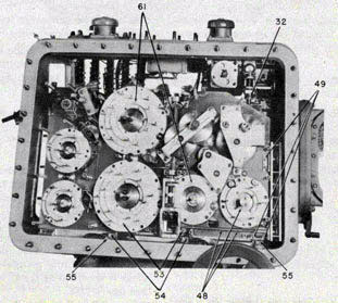
48. Now, remove sight angle dial gear assembly and then drive two pins out of collar 422937-
9, at the base of the computer and slip collar as far to the left as possible. See figure 113.
49. Remove three mounting screws holding the clamp at the bottom of the external lighting type
bearing receiver gear box which is attached to the right side of the computer. See figure 113.
50. Pry lower bracket loose from dowel pins and remove the gear box from computer.
51. Examine the gear box for free running of gears, corrosion and dirt. Clean, and then tag gear
box with the director number.
Computer.
52. To remove the computer, start by taking off the grease cover 168081-18 on the rear of the
case at training circle. Then remove the mounting screws 168076-7 which hold the stop
bracket to the face of computer. See figure 112.
53. Remove main dial group "A" gear assembly. Figure 113.
54. Remove six mounting bolts which hold the computer to the case. Be sure to mark the exact
location of each of these mounting bolts as they must be inserted in their original
115
TORPEDO FIRE CONTROL EQUIPMENT (DESTROYER TYPE) OP 1586
Figure 109-Removal of Wires and Terminals.
locations during the assembly procedure. See figures 112 and 113.
55. Drive the two dowel pins in front of the computer mounting pads far enough through the
bottom of the case to clear the computer. See figure 113.
56. Remove bolt securing terminal bar bracket 168056-12 to computer. See figure 112.
57. Remove five screws holding terminal block to bracket and drop the bracket as much as
possible. Figure 112.
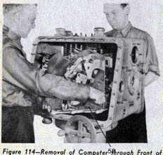
58. To remove the computer from the case, tip the right-hand side of the computer upward as
far as possible and slip the unit through the front of the director case. See figure 114.
Caution. In removing the computer, exercise extreme care to prevent damage to the
transmitter unit gears. Place the computer assembly on the work bench.
59. Now, operate the computer assembly, manually, by turning any one of the input gears.
Check for (1) excessive looseness or binding in gear trains, (2) faulty operation of follow-up
switch, (3) looseness of "T" racks in guide rails, (4) excessive backlash in gear trains
connecting DF6 to "T" racks, (5) binding angle solver rollers, (6) excessive end shake in angle
solver guide rollers, (7) rusty bearings and dirt, etc., (8) bent shafts, (9) loose taper pins
and sprung gears. If any of the above faults are observed, disassemble the computer in
accordance with procedure given below.
60. To disassemble the computer, perform
steps 61 to 73.
116
DISASSEMBLY AND OVERAUL-DIRECTOR
Figure 110-Removal of External Lighting Type Bearing Receiver.
61. Remove the two dial gear assemblies from the front plate of the computer. Inspect and clean
all dial gear assemblies. See figure 113.
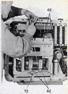
62. Remove the back plate assembly and the sight angle follow-up motor. Test the motor and
recheck the assembly for loose taper pins and bent shafts. See figure 115.
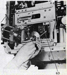
63. Remove the follow-up switch. Check for burnt points, check condition of contact arms and
pressure springs and smoothness of gear mesh. See figure 116.
64. Remove and inspect traveling nut and two intermittent gear limit stops. See figure 117.
65. Remove the front plate assembly. This operation exposes the differential gear box. See
figure 117.
66. Remove the gear box. Check the differentials for free action, backlash, rusted bearings,
dirt, etc. The movement of the differentials
Figure 111-Removal of Internal Lighting Type Bearing Receiver.
should be extremely free with an absolute minimum of backlash. See figure 119.
67. To remove the angle solvers in the computer, start with the removal of the sight angle
zero-reader dial bracket. See figures 117 and 118.
68. Remove "T" racks by removing eight screws holding guide rails. Slide the guide rails out and
withdraw "T" racks. See figures 118 and 119.
69. Remove plate supporting the front angle solver assembly. See figure 118. Then, check the
guide rollers for free movement and fit of cam follower in cam groove. This follower should
move freely along the entire length of the groove. Maximum clearance of cam in groove should
not exceed 0.0005 inches. Check the action of the sliding member in the radial slot gear. It
should slide freely without lost motion. See figure 120.
70. Repeat procedure in paragraph 69 for back angle solver.
117
TORPEDO FIRE CONTROL EQUIPMENT (DESTROYER TYPE) OP 1586
Figure 112-Removal of Own Ship Course Unit and Computer.
Figure 113-Removal of Computer.
118
DISASSEMBLY AND OVERAUL-DIRECTOR
71. Check the remaining computer gearing, shafting and bearings for straightness, rust, dirt,
etc. Clean all parts of computer in an approved cleaning solution.
72. For Torpedo Director Mk 27 Mods 1, 2 and 3, constructed previous to Mods 4 and 5, the
center mounting bolt on the rear of the computer which holds it in place is in an upside-down
position. Before removing the mounting bolts it is necessary to remove the back plate assembly
of the computer. See figure 115.
73. Before removing the transmitter from the case, test the synchro generators by hooking
them to a synchro receiver unit. Now, crank in a position by means of the connecting gear and
observe whether the output signal agrees with readings on the torpedo course and gyro angle
dials.
Note: Use the check dials for accurate reading of torpedo course dials.
74. Loosen and remove the case flange nut 168019-1. See figure 121.
Transmitter.
75. To disassemble the transmitter, break and unlace all terminal connections in the director
case. See figures 121 and 123.
Figure 114-Removal of Computer Through Front of Case.
Figure 115-Removal of Back Plate Assembly.
Figure 116-Removal of Follow-Up Switch.
119
TORPEDO FIRE CONTROL EQUIPMENT (DESTROYER TYPE) OP 1586
Figure 117-Steps in Disassembly of Computer.
Figure 118-Removal of Angle Solvers
.
76. Then, remove the back post by withdrawing three mounting bolts. Identify and locate these
bolts so they can be replaced in their original positions. Figure 121.
Figure 119-Removal of Gear Box and "T" Racks.
Figure 120-Removal of Supporting Plate from Front Angle Solver.
77. Now, remove the three mounting bolts holding the transmitter in the director case. Mark
each bolt and its location so it can be replaced in the same location during reassembly.
120
DISASSEMBLY AND OVERAUL-DIRECTOR
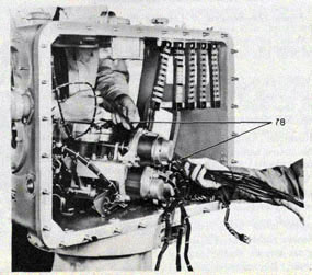
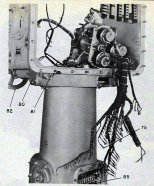
Figure 121-Removal of Back Post and Transmitter.
Figure 122-Loosening Main Cable Wires.
121
TORPEDO FIRE CONTROL EQUIPMENT (DESTROYER TYPE) OP 1586
Figure 123-Removal of Locating Pin and Handwheel Shaft.
Now, tip and lay transmitter on its left side. See figure 121.
78. Loosen main cable wires from case terminal boards and pull main cables through
transmitter grommets, then remove transmitter through front of case. See figure 122.
79. Place the transmitter unit on a workbench and inspect the entire assembly for free running
of gears, bent shafts, damaged gear teeth, corrosion, dirt, etc. If it is necessary to remove a
faulty synchro generator refer to procedure detailed in chapter 9.
80. Remove the access cover plate from inspection opening on lower right side of director case
by withdrawing six screws. Drive locating pin out of worm gear. Pin can be reached through
inspection opening. See figure 123.
81. Remove double nut from worm at the rear of the training handwheel shaft. See figure 123.
82. Upon completion of unpinning, remove the handwheel shaft by withdrawing it from the
front. This will loosen the worm gear which should also be removed. See figure 123.
83. To remove the case from the stand; first, loosen main cable from stand terminals then,
loosen and remove 12 fiat head mounting screws in the bottom of the case. See figure 121.
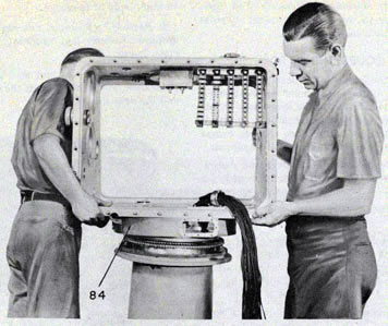
84. With the assistance of one other man, lift the case from the stand. See figure 124.
Stand.
85. The first step in disassembly of the director stand is to unscrew and remove the
122
DISASSEMBLY AND OVERAUL-DIRECTOR
Figure 124-Lifting Case from the Stand.
Figure 125-Removal of Inner Bearing.
terminal boards from one side of the stand. Then inspect the boards for cracks, loose terminals,
corrosion, etc. See figure 123.
86. Reach into the stand and remove six flat screws holding the inner bearing plate of the
training circle and stop bracket assembly. See figure 125.
87. Now inspect the felt grease seal. If worn, or damaged replace the seal.
88. Liftup and remove the inner bearing. Examine this assembly for rust or corrosion. See
figure 125.
89. Inspect training circle and ball bearing for free running, chipped gears, corrosion, etc.
90. Inspect training stop assembly, examine the rubber bumpers and spring. If damaged or
worn, replace. See figure 125.
91. The transfer switch and remaining terminal boards in the stand can be removed if condition
warrants. If it is necessary to remove the selector switch, refer to chapter 9.
123
TORPEDO FIRE CONTROL EQUIPMENT (DESTROYER TYPE) Op 1586
92. To complete the overhaul, clean all assemblies with Solvent-Dry Cleaning (Fed. Spec. P-S-661) or its approved equivalent. Repaint all dials with translucent paint.
TORPEDO COURSE INDICATOR
1. After the indicator has been removed from the torpedo course attachment on the torpedo tubes
and transferred to the shop, tests should be run after wiring the indicator synchros to a synchro
test unit. Introduce torpedo course and gyro angle orders and note discrepancies.
2. Remove indicator back cover and disconnect lightwell leads from terminal board. See figure 126.
3. Now remove the front cover. See figure 127.
4. Inspect lightwells and wiring and condition of glass and gaskets. See figure 6. Check the condition of the dials and the paint. Check the free running of synchros by turning the inner dials slowly. See figure 127.
5. For removal of all synchros, refer to chapter 9.
6. Loosen five cap screws which secure the indicator chassis to the case. Now, remove the
chassis. See figure 128.
7. Inspect the assemblies for free running of gear trains, bearings and bent shafts. Examine the
mechanism for rust, dirt, etc. See figure 128.
8. Check the indicator differential assembly. If faulty, remove and make necessary repairs. See
figure 128.
DISASSEMBLY OF TELESCOPE
To disassemble, proceed as follows:
1. Remove objective window retainer and objective window.
2. Remove all cover plates.
3. Remove prism mount and prism.
4. Remove screws from mirror journal bearing. Remove bearings, mirror and its mount.
5. Remove color filter mount from its shaft. The shaft must be removed. Remove knob, packing
gland, and packing. The collar over packing
gland is held in place by a pin. Remove shaft through body of telescope.
6. Remove lock screw, unscrew and remove eyepiece. Remove lens retaining ring and remove lenses.
7. Remove lock ring and with puller remove inner tube. This tube contains the objective lens
and the crossline plate.
Figure 126-Removal of Indicator Back Cover.
Figure 127-Removal of Indicator Front Cover.
124
DISASSEMBLY AND OVERAUL-INDICATOR
Figure 128-Removal of Chassis and Inspection of Assemblies.
735193-47-9
125
TORPEDO FIRE CONTROL EQUIPMENT (DESTROYER TYPE) OP 1586
Section 2-ASSEMBLY AND ADJUSTMENT
Torpedo Director
1. Take the director stand and place it on assembly platform or secure it to the floor. Be sure to
fasten securely to prevent tipping after case has been attached. See figure 129.
2. Install main cable in the gland of the stand inner bearing. See figures 129 and 130.
3. Reassemble the inner bearing and training stop mechanism, place in stand, and secure to
bottom plate. See figure 129.
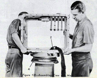
4. With the help of another man lift the case and place it over the two dowels on the top of the
stand inner bearing. The inner bearing contains a gland which extends at a 45 degree angle from the
bearing. This gland must be placed directly in front of the center rectangular transmitter pad
projecting above the base of the case. See figure 130.
5. Now, fasten the case to the inner bearing with 12 flat head machine screws. See figure 131.
6. Insert training handwheel and shaft through the drilled passage in the bottom of the case.
Before sliding the shaft past the
Figure 129-Assembly of Stand, Main Cable, Inner Bearing, and Training Stop Mechanism.
Figure 130-Assembling Case and Main Cable
126
ASSEMBLY AND ADJUSTMENT-DIRECTOR
Figure 131-Fastening Case to the Inner Bearing.
Figure 132-Assembling the Transmitter
.
access opening on the right side of the case, insert the compression worm gear through the
opening and slide the worm over the handwheel shaft. Drive the shaft home until it protrudes
through the base of the case. Lock in place with two takeup nuts and a bushing. Adjust nuts on
end of the training shaft for the compression worm so that lost motion is reduced throughout the
limits of train of the director to the lowest value consistent with
freedom from binding. Torque at training handwheel should be between 20 and 30 in./lbs.
Transmitter Assembly.
7. If the transmitter assembly has been dissembled for an overhaul, perform the following
steps to reassemble. See figure 132.
a. Install gearing and shafting assemblies
b. Clamp synchro generators in chassis.
c. Attach dials and dial gear assemblies to the front plate of the transmitter.
d. Insert light rods and shields.
e. Attach dial shields and light reflectors.
8. Zero all synchro generators of transmitter with dials. Refer to OP 1303 for procedure.
9. Pick up the transmitter unit and place in the left side of the director case. See figure 133.
10. Place the transmitter over the two dowel pins in the front of the case.
11. Now, feed the main cable, protruding from the inner bearing gland through the two rubber
grommets in the lower portion of the transmitter frame. Be sure to allow a loop in the cable
where it extends beyond the back of
127
TORPEDO FIRE CONTROL EQUIPMENT (DESTROYER TYPE) - OP 1586
Figure 133-Replacing Transmitter and Main Cable.
the transmitter frame after slipping the rubber bushing and clamp over the cable. See figure
133.
12. Bolt the transmitter securely in place, using the four previously identified bolts.
13. Train the director so that when looking forward, the selector switch on the stand is
pointing
toward the left for a starboard director and toward the right for a port director. Check to see
that the dial face of the case is parallel with the machined surface of the terminal board
access
port of the director stand. This may be accomplished by dropping a plumb bob from each corner
of the case and aligning
the bob cords with the machined surface of the access port. See figure 133.
Back Post.
14. Install the back post. See figure 134. Do not pull down too much on the three mounting bolts
until you have made sure the beveled gear on the lower portion of the drive shaft meshes
properly with the micrometer adjustment gear on the BTO-2 shaft of the back post. Be sure to
place the spacer beneath back post. See figure 134.
15. Screw the resistor block in place to the
lower portion of the fuse box opening. See figure 144.
128
ASSEMBLY AND ADJUSTMENT-DIRECTOR
Figure 134-Installing Back Post, Main Cable, and Terminal Blocks.
16. Now, run main cable up through rubber bushing at left side of director case. See figure 134.
17. Take the five case terminal blocks and screw them in place in the upper left rear portion of
the case. The terminal block nearest the center of the case bears the number U2B at the top, the
adjoining has the number U2A, the following the number L17, the next number Y1 and the block
nearest the left side of the case the number T1. See figure 134.
18. The clips on the ends of the wires forming the main cable are numbered. The bus bars on the
terminal blocks, the resistor and the fuse box panel are also numbered. Fasten the numbered
clips of the main cable wires to the proper locations on the terminal blocks, resistor and fuse
panel-refer to BuOrd Dwg 168050.
Computer Assembly.
19. To assemble the computer, follow the outline below. See figures 135 to 139 and 141.
a. Secure angle solvers to front and back plates.
b. Install angle solver guide rollers.
c. Insert solver guide rails and T racks, then align guide rails with bottom and back of computer chassis.
d. Tighten guide rails to guide rail supports.
e. Install DF-4, DF-5, DF-6, and related gearing and shafting.
f. Install differential gear box containing DF-1, DF-2 and DF-3.
g. Attach limit switch.
h. Install zero reader dial assemblies.
129
TORPEDO FIRE CONTROL EQUIPMENT (DESTROYER TYPE) - OP 1586
i. Complete installation of remaining gearing and shafting.
j. Attach front plate.
k. Install intermittent gear stops.
Gear Stop Adjustments.
20. In order to obtain the proper range of speed between the extremes of the intermittent gear
stops, certain adjustments must be made. See figures 140 and 141.
a. To adjust the torpedo speed limit stop, drive pin from bronze gear on end of DS-4 shaft and
push the shaft assembly forward until it is disengaged from DF-5. Now rotate the back angle
solver spiral gear so that the follower pin of the solver moves toward the center of the gear.
When the follower pin has reached the inner end of the spiral and the blued gauge
marks of the radial gear, I rack and guide rail are in alignment, rotate the spiral gear in the
opposite direction from four to six teeth. Now slide the DS-4 shaft back to original position and
mesh gears. Reinstall taper pin in bronze end gear.
b. To adjust the target speed limit stop, drive pin out of gear on St-2 shaft and push gear out
of mesh with St-3 shaft. Turn the St-6 shaft clockwise until the pin of the intermittent gear hits
the limit stop. Now rotate the spiral gear of the front solver until the follower pin reaches the
inner end of the spiral groove and the blued gauge on the radial gear, I rack and guide rail are in
alignment, then reverse the rotation of the spiral gear approximately one-half inch. Now push the St-6 shaft back to its former position and
Figure 135-Computer Assembly
130
ASSEMBLY AND ADJUSTMENT-DIRECTOR
secure the gear in proper mesh. Replace gear taper pin.
c. To zero the computer manually, line up blued gauge marks on both solver gears, T rack and
guide rail. The follower pin should be toward the bottom of the spiral groove and radial slotted
gear should be pointing vertically.
d. The micrometer adjustment gear on the end of DF-6 should be set so that the adjusting screw
is vertical. See that the pin on the electrical limit switch is also vertical. See figures 140 and 141.
e. Rotate the drive gear on the follow-up switch counterclockwise until the pear-shaped cam
actuates the contact arm. When this switch is properly set, the contact arm will move clockwise.
f. Install follow-up switch in this position and mesh gear with driving gear in the computer.
g. Attach computer back plate.
h. Attach dial assemblies minus dials.
i. Adjust all gear meshes to a minimum backlash consistent with free running.
j. Carefully insert the computer assembly from the front of the case by slightly elevating the
right-hand side. See figure 114.
Caution. Use extreme care not to damage exposed computer and transmitter gears.
21. Place computer on the two dowel pins in front of case and check to see that the connecting
gears of the computer and the transmitter mesh properly.
22. Tighten six previously identified computer bolts to bottom of case. The center rear
Figure 136-Installing Front Plate, Gear Stops, and Dial Assemblies.
131
TORPEDO FIRE CONTROL EQUIPMENT (DESTROYER TYPE) OP 1586
mounting bolt should be inserted from below the case through the computer frame. See figure 141.
Own Ship Course Assembly.
23. To assemble the own ship course unit, follow the outline given below. See figure 142.
a. Assemble the worm gears and shafts in chassis,
b. Install bearings and gears on the synchro motor.
c. Clamp the synchro motor in chassis.
d. Attach the servo motor to chassis.
e. Attach the capacitor to the chassis.
f. Install the heart-shaped cam follow-up switch.
g. Mount the dial support bracket.
Note: Do not attach dial and dial shield to own ship course assembly until unit has been secured to
the director case. This prevents scratching of the dial and shield.
24. From the back end of director case insert the own ship course unit. Since this unit is
fastened to the top of case, it requires the services of two men to hold it in the proper position.
Be sure the Oldham coupling is connected
Figure 137-Attaching Limit Switch.
Figure 138-Installation of Gearing and Shafting.
132
ASSEMBLY AND ADJUSTMENT DIRECTOR
Figure 139-Installing Zero Reader Dials, Gearing, and Shafting.
Figure 140-Gear Stop Adjustment Points.
735193-47-10
133
TORPEDO FIRE CONTROL EQUIPMENT (DESTROYER TYPE) OP 1586
Figure 141-Installation of Limit Switch and Differential Gear Box.
properly. After the own ship course unit is in place, secure it with five bolts inserted through
the top of the case. See figures 108 and 143.
To determine the time required for the own ship course receiver to reach synchronism with the
synchro test unit, engage the own ship course handwheel on the director for "0 degrees" dial reading
and set the synchro test unit transmitter at "180 degrees". Release own ship course handwheel on director to
energize own ship course follow-up system. Repeat using 180 degrees on director own ship
course dial and 0 degrees on test transmitter. Record time necessary for own ship course unit to
reach synchronism with test transmitter. Maximum allowable time to reach synchronism is 28
seconds.
Check operation of sight angle cutout switch to see that it operates freely and in good order.
Caution. Be sure lightwell wires in top of case do not become fouled on own ship course unit.
Figure 142-Assembling Own Ship Course Unit.
134
ASSEMBLY AND ADJUSTMENT-DIRECTOR
25. Install terminal bar bracket 168056-12 on left rear side of computer and attach to the
five terminal bars recently installed.
26. Screw the clips on wires R1F, R2F, S1F, S2F, S3F, V1, V2, B1, U2A, and U2B to same
numbered bus bars on terminal blocks in back of the director case. See figure 143.
27. Screw the clips on wires W1, W2, V10, V20, M2C, and M1C to similar numbered terminals
on fuse block.
28. Place and secure wire numbered B1 to the resistor block.
29. Take the computer wires marked M1OL, M1OR, M1R, and M1L and attach to capacitor.
Bearing Receiver Assembly.
30. Insert the gear box for the external lighting type bearing receiver over the dowels in the computer plate and attach the upper and lower
gear box brackets to the front plate of the computer.
31. The two-piece shaft, at the bottom of the gear box, connecting the computer to the bearing receiver gear box should be connected as a unit by centering collar 422937-9 over the two ends. Fix the collar in place by inserting two taper pins.
32. Now install traveling nut stop bracket assembly to front plate of computer.
33. Pick up the bearing receiver connection cable and extend it through the side of the case. Slip the external light type bearing receiver over the four studs of the mounting pad on the right side of the case. Make sure the male end of the Oldham coupling is properly seated in the gear box. Lock in place with four elastic stop nuts.
34. Connect the bearing receiver electrical cable to the receiver terminal block.
Figure 143-Replacing Own Ship Course Unit and Terminal Block Wiring.
135
TORPEDO FIRE CONTROL EQUIPMENT (DESTROYER TYPE) OP 1586
Figure 144-Check Position of Points on Follow-Up Switch. Screw Resistor Block in Place.
35. Attach the own ship course and sight angle hand cranks to the right side of the director case.
Allow sufficient backlash in gears to permit engaging of hand crank without binding.
36. To install internal lighting type bearing receiver:
a. Attach receiver case to the front right side of the director case with four bolts.
b. Slip main cable through port in director case and make connection to terminal block and
bearing receiver synchros.
c. Insert and connect Oldham coupling.
d. Insert receiver chassis in receiver frame and bolt in place.
Note: Do not attach cover until after zeroing receiver and computer dials.
e. Connect main cable to terminal block in back of case.
37. Replace the light rod on the front of the
computer; see that end of rod is at least 3/8 inches from lightwell.
38. Center the traveling nut on the stop bracket 422933-1 between the stop nuts with the
intercept offset dial at zero.
39. Install all light reflectors on dial shields. See BuOrd Dwg 251543.
40. Install dial shields in director.
41. Attach latitude correction dial, set at zero.
42. Install intercept offset dial and set dial so it will rotate in each direction the same
distance without hitting stop.
43. Train the director with the handwheel until check dials of the transmitter zero
136
ASSEMBLY AND ADJUSTMENT-DIRECTOR
accurately. The check dials are visible through the opening for the gyro cover.
44. Lock the training wheel to maintain the transmitter at zero. (Lock with wedge.)
45. Set the computer on approximate zero by rotating the sight angle hand crank and bevel gear
168071-7 until the blued mark on the slotted gears is approximately lined up with the blued
mark on the T racks, and the guide rails. Rotate the scroll gear by turning the gears
counterclockwise to the stops then turn clockwise until the blued marks line up with the blued
marks on the T racks and the guide rails.
46. Mount the corrected sight angle and the own ship outer ring dials on the computer at
approximately zero position.
47. Install the target outer ring dial with zero on the dial to the top. This setting is
approximate
as final zeroing of the dials will be performed in a later operation.
Caution. Make sure 0.003-inch clearance is allowed around each dial.
48. Temporarily attach the front cover or a dummy cover to the director case. If the front
cover is used, remove dial windows on the computer end.
49. Mount all hand cranks. Make hand crank friction adjustments with following torque ranges:
Gyro Angle (Bgy) 3.5 to 6.0 in./lb.
Tube Offset (Otu) 4.0 to 6.5 in./lb.
Target Course (Ct) 3.3 to 4.8 in./lb.
Target Speed (St) 3.3 to 4.8 in./lb.
Torpedo Speed (Sto) 3.75 to 6.0 in./lb.
Own Ship Course (Co) 3.5 to 6.0 in./lb.
Sight Angle (Ds) 3.5 to 6.0 in./lb.
Above torque values are applicable after installation of hand crank assemblies. Gear clutch
friction should be set to 30 in./lb. Hand crank gears should not bottom or have excessive
looseness, and should operate smoothly.
Zeroing the dials.
50. Accurately zero the computer by performing the following steps.
51. Install torpedo speed and target speed dials.
52. Mount intercept offset, latitude correction, torpedo speed, target speed tube offset, and target
course hand cranks on the cover. Move the cranks on the mounting screws to eliminate excessive
backlash between mating gears.
53. Engage the own ship course hand crank and loosen clamping screw on own ship course
Oldham coupling.
54. Set check dials in transmitter on exact zero. Use a wooden wedge for locking the training
handwheel.
Note: While zeroing the director dials on the computer, care should be used not to move the
training handwheel.
55. Set intercept offset dial accurately on zero with the index on the dial shield by turning
the intercept offset knob.
The intercept offset knob may have to be removed and the bevel gear 422947-1 slipped slightly
so the knob will be in one of the detents and the dial will be on zero.
56. Check clearance between the sight angle reader dials and the dial shields. These dials must
have 0.003-inch clearance between the dial shields as any binding will affect zeroing of computer.
Steps for Setting the Dials.
57. Run torpedo speed dials to the stop on the increasing side.
58. Check position of points on the follow-up switch and if points are notYen centered, rotate sight
angle hand crank until points center. See figure 144.
59. Run the torpedo speed dial back to the stop on the decreasing side and watch points to see if
they move. If the points move, repeat operations 57, 58 and this operation until points do not
move off the center.
60. Run the target speed dial to the stop on the increasing side.
137
TORPEDO FIRE CONTROL EQUIPMENT (DESTROYER TYPE) OP 1586
61. Check points on the follow-up switch and if the points are not centered turn the target
course. hand crank until the points center.
62. Run the target speed dial back to the stop on the decreasing side. If points move, repeat
operations 60, 61. and this operation until points center while running the target speed to the
stop and back.
63. Slip the outer dials on the target main dial and the own ship main dial by loosening clamping
rings 168072-1 and clamping screws 168070-5. (See BuOrd Dwg 168008, general
arrangement.) Set the outer dial on the target main dial with the 180' mark at the index and the
outer dial on the own ship main dial with zero at the index Tighten the screws 168070-5 on the
clamping rings.
64. Install the inner dial assembly on the target main dial with the zero at the 180 mark of the
outer ring dial.
65. Install the inner dial assembly on the own ship main dial assembly with the zero at the zero
mark of the outer ring dial.
66. Set the inner dial zero of the target main dial at the 270 degree mark of the outer dial by turning
the target course hand crank.
67. Check points on the follow-up switch and, if not centered, move the target speed hand crank
until points center.
68. Turn the inner dial zero on the target main dial to the 90 mark on the outer dial.
69. Check the points on the follow-up switch and if not centered adjust points by turning the
target speed hand crank. Repeat operations 66, 67, 68, and this operation until points hold
center and the inner dial of the target main dial is at the 270 degree mark and the 90 degree mark of the
outer ring dial.
70. After completing operation 69 loosen the clamping screws on target speed dial. Zero dial and
tighten the clamping screws.
71. Set the inner dial of the own ship main dial at zero on the 90 degree mark of the outer ring dial by
turning the sight angle hand crank.
72. Check points on the follow-up switch and if not centered move points to center by turning
the torpedo speed hand crank.
73. Set the inner dial zero of the own ship main dial at the 270 degree mark of the outer ring dial by
turning the sight angle hand crank.
74. Check points on follow-up switch and if not centered adjust points by turning the torpedo
speed hand crank. Repeat operations 71, 72, 73, and this operation until points hold in center,
with the inner dial of the own ship main dial zero at the 90 degree mark and the 270 degree mark on the
outer ring dial.
75. After completing operation 74, loosen the clamping screws and zero torpedo speed dial and
tighten clamping screws.
76. Turn the sight angle hand crank until the outer ring dial of the own ship main dial assembly
is at zero.
77. Install the center dial 168067-4 on the target main dial with the index at zero with the
pointer on the dial shield 168066-2 and clamp in place.
78. Install the center dial 168067-3 in the own ship main dial and zero pointer with pointer
on the dial shield 168066-2 and clamp in place.
79. Loosen the four screws 168070-5 on the clamping ring for the dial carrier of corrected
sight dial of the sight angle dial assembly. Set ring dial on zero and tighten the four clamping
screws 168070-5.
80. Set basic sight angle dial 168070-6 on zero and replace clamp and clamping screws.
81. Connect terminals 43 and 44 located in the director stand to a 110-volt 60-cycle a-c supply.
82. Set selector switch to "ON" position.
83. Set transformer switch to "TRANSFORMER" position.
84. Disengage sight angle hand crank.
85. Run the torpedo speed dial to 60 knots and the target speed to 50 knots.
138
ASSEMBLY AND ADJUSTMENT-DIRECTOR
86. Turn the target course hand crank until the inner dial zero, of the target main dial is at
90 degrees and let director run until the computer stops.
87. Run the inner dial of the target main dial back to zero.
88. Check all dials to see if they come back to zero position: If dials do not come back to zero
then an error has been made in setting the dials and must be corrected by manually zeroing the
computer and resetting the dials that may be off. Operations 57 through 87 are necessary for
setting the dials.
Tolerances for allowable off-set of dials with indexes are:
(1) Target speed dials shall be zeroed with the index within 0.008 inches when the target
course is at 90 and 270 degrees with the follow-up points centered.
(2) The torpedo speed dial shall zero with the index within 0.008 inches when the telescope is
rotated to 315 and 45 degrees with the follow-up points centered.
(3) The target course and the own ship course dials shall zero within 0.006 inches when the
target speed dial is set at zero within the given tolerances.
89. Tighten clamp of Oldham coupling between the own ship course unit and the computer
leaving not more than 0.008-inch lateral clearance in the coupling.
Hand Cranks.
90. Remove the target speed, torpedo speed, target course, intercept offset, latitude correction
and the tube offset hand cranks from the dummy cover.
91. Remove cover from the director.
92. Touch up the screw heads and dial shields with a flat black enamel.
93. Replace the front cover 168032-1 on director and screw in place with cap nuts.
94. Replace target speed, torpedo speed, target course, latitude correction, tube offset, and the
intercept offset hand cranks. Check fit between mating gears and correct if necessary.
95. Set the director dials and check dials on the transmitter at zero and install pivot with the
index on the pivot at zero.
Note: The center piece of the Oldham coupling should be in position before replacing the securing nuts.
96. Replace telescope pivot wires T1, T2, Y1, Y2, L7, and L17 to the terminal blocks in the
back of the director.
97. Energize the own ship course by wiring a dummy transmitter to the director. (See BuOrd
Dwg 168050, wiring diagram.)
98. Set the dummy own ship course transmitter at zero.
99. Loosen the clamping screws on the heartshaped cam assembly on the own ship course unit,
then hold points to either side until the inner dial on the own ship main dial approximates
zero.
100. Turn selector switch to "OFF" position.
101. Tighten clamping screws on the heartshaped cam assembly, tight enough to hold on the
shaft, but not so tight that tapping the clamp will not permit it to slip.
102. Turn selector switch to "ON" position.
103. Tap the clamp on the heart-shaped cam assembly until the inner dial on the own ship
course dial assembly accurately zeros. -
104. Turn selector switch to "OFF" position.
105. Tighten clamping screw on the clamp for the heart-shaped cam assembly.
106. On the own ship course unit, replace the dial shield 168038-i and the light reflector
251580-1 as shown on BuOrd Dwg 251570.
107. With own ship course on electrical zero, replace the own ship course reader dial with the
indexes at "0" and clamp in place.
108. Check sight angle reader dial and if not zeroed, reset by loosening clamping screws and
rotate dial to "0".
109. Replace the two window covers 168032-3 over the own ship course and the sight angle
reader dials.
139
TORPEDO FIRE CONTROL EQUIPMENT (DESTROYER TYPE) OP 1586
110. Replace the front cover 168033-1.
111. Install the fuse block 168056-1 in place on the director case and screw in place with six
screws 12-Z-42-30.
112. Install the fuse box cover 168055-1 by fitting the cover in place on the director and
sliding the rod 168055-4 through the holes in the lugs and pinning with two cotter pins 12-Z-48-214.
113. Replace the gyro cover 168032-2.
Telescope.
114. Attach the telescope to the telescope pivot.
115. Loosen screw on adjusting clamp 422941-4. (See BuOrd Dwg 422911, general
arrangement.) An access hole is provided in the chassis 422930-1 and the adjusting clamp
should be held in position until after zeroing the bearing -receiver with the director. With the
torpedo director zeroed, rotate the lower ring dial until both dials are zeroed with the index on
the center of the dial shield. Tighten adjusting clamp.
116. With the director energized, engage the sight angle hand crank and rotate a few turns in
either direction. Disengage the hand crank and allow director to zero electrically. Check dials on
the bearing receiver and if they are not at zero, zero them.
117. Connect cable to bearing receiver terminal bar and transmit signal after hooking up to dummy synchro.
118. Set dummy synchro on zero and zero the inner dials of the bearing receiver to the outer
dials.
119. Replace the cover on the bearing receiver and bolt in place.
120. Zeroing Internal Lighting Type Bearing
Receiver. The 1- and 36-speed dials are set to each other and the fixed index by means of the
adjustment clamp on the 48-tooth adjustable hub spur gear in the unit. This need only be done
at initial assembly or if the unit is disassembled.
With the director relative bearing on zero, the bearing receiver is set to exactly zero by
means of the adjustment clamp on the adjustable hub bevel gear on shaft BS5 in the director.
121. Perform electrical tests listed below.
122. Dielectric Test. For circuits which have a nominal potential of less than 25 volts, apply an
alternating current potential of 115 volts between the terminals and ground. For circuits which
have a nominal potential between 25 and 125 volts, apply an alternating current potential of
1,000 volts between the terminals and ground. Circuits, or groups of circuits of different
voltages, shall be tested separately. The voltage shall be raised slowly to the specified value and
held at that value for one minute, and then gradually reduced. The wave form of the applied
voltage shall be approximately sinusoidal. There shall be no breakdown of insulation or arcing.
123. Illumination circuit at 115 volts: Turn crossline illumination rheostat to "ON" before megger test.
124. Firing key circuit-test at 115 volts.
125. Firing signal circuit-test at 115 volts.
126. Battery circuit-test at 115 volts-lamps removed from sockets. Turn battery switch to "ON".
127. Heater circuit-test at 1,000 volts-megger to ground only. Continuity between pairs of conductors.
128. Power line circuit-test at 1,000 volts.*
129. Own ship course circuit-test at 1,000 volts.*
130. Magnetic brake circuit-test at 1,000 volts.*
131. Insulation Resistance. Immediately after satisfactorily passing the dielectric test, each
circuit shall show an insulation resistance of at least 5 megohms when a potential of 500 volts,
direct current, is applied between a terminal and the ground. (This resistance test is to be run
with lamps removed from sockets.)
*Close sight angle switch and own ship course switch before megger test.
132. Dielectric Test-Synchro System. Apply an alternating current potential of 1,000 volts
140
ASSEMBLY AND ADJUSTMENT-INDICATOR
Figure 145-Assembly of Torpedo Course Indicator.
between R1 and ground, S1 and ground and between R1 and S1. Each circuit, in addition to L10 to
ground and L20 to ground, shall show an insulation resistance of at least 5 megohms when a
potential of 500 volts, direct current, is applied between the terminal and ground.
TORPEDO COURSE INDICATOR
See figure 145.
1. Secure indicator case and install differential.
2. Replace all dial gearing and shafting on chassis.
3. Clamp the three synchro motors in the chassis.
4. Mount the chassis in case.
5. Connect all synchro wiring to the terminal board.
6. Mount dials, dial shield, light rod, and reflectors.
7. Set zeros on dials to match indexes on dial shields.
8. Set synchro dials on zero. Refer to OP 1303 and use special tool 8-Z-940.
9. Feed lightwell wires into case and place front cover in place.
10. Secure front cover and secure lightwell wire to terminal board.
11. Replace back cover.
ASSEMBLY OF TELESCOPE
The assembly operations are performed in the reverse order of the disassembly operations.
141
APPENDIX
There are certain data pertaining to the Torpedo Fire Control System which cannot be placed in
the foregoing chapters, but which are nonetheless important. These items are all grouped under
the heading, "Appendix".
GENERAL INFORMATION
Locations
Director-on the bridge of destroyers, port, starboard, or centerline installations.
Indicator-mounted on torpedo course attachment above torpedo tube mounts.
Telescope-mounted on telescope pivot on the top of the torpedo director.
Firing Key-clamped in a bracket at the side of the telescope.
Dimensions
Director-66 by 45 by 29 inches.
Indicator-20 1/4 by 21 by 9 inches.
Telescope-10 by 24 by 10 inches.
Firing Key-8 by 2 inches.
Director Spare Parts Box-25 1/2 in. long, 16 1/2 in. wide, 12 1/2 in. high.
Weights
Director (without telescope or firing key)-750 lbs.
Indicator-77 lbs.
Telescope (without firing key or firing key bracket) -43 lbs.
Firing Key and Bracket-4 lbs.
Director Spare Parts-75 lbs.
Terminal Tubes
Director-refer to elementary wiring diagram.
Indicator-refer to elementary wiring diagram.
Electric Cables
Director-refer to elementary wiring diagram.
Indicator-refer to elementary wiring diagram.
Indicator lights for original design.
Bearing Receiver Mods 7, 8, 9-three Navy type VG-7.
Indicator lights for later design.
Bearing Receiver Mods 7, 8, 9-two Navy type VG-7.
Synchros
Director:
Generators-five type 5G.
Generators (Mod 2 only)-seven type 5G.
Motors-one 5B.
Motors-two 1F.
Indicator:
Motors-three type SF.
Motors (Mod 3 only) -two type 5F.
Servos (Follow-up Motor)
Director:
One 1/200 hp Type Induction Capacitor.
One 1/50 hp Type Induction Capacitor.
142
APPENDIX
INPUTS AND OUTPUTS
Hand Inputs
Electrical (Speed)
Mechanical Inputs
Usage
Speed
Per Turn
Per Click
Input
Output
Speed
Per Turn
Director
Own Ship Course
180
2o
Instead of synchro follow-up.
Sight Angle
180
2o
Instead of servo follow-up.
Target Speed
2 knots
Initial and subsequent settings.
Target Course
90
4o
Initial and subsequent settings.
Torpedo Speed
2 knots
Initial and subsequent settings.
Torpedo Course (or Relative Target Bearing):
Mods 1,2,3,7
180
2o
Initial and subsequent settings.
Mods 4,5,8,9
120
3o
Initial and subsequent settings.
Latitude Correction
180
2o
10'
Initial and subsequent settings.
Intercept Offset
180
2o
10'
Initial and subsequent settings.
Tube Offset
180
2o
Initial and subsequent settings.
Gyro Angle Order
72
5o
Initial and subsequent settings.
Relative Target Bearing
1&36
Own Ship Course
1
Torpedo Course Order
1&36
Gyro Angle Order
2
Indicator
Torpedo Course Order
1&36
Gyro Angle Order
2
Tube Train
18
20
Gyro Angle
36
10
143
TORPEDO FIRE CONTROL EQUIPMENT (DESTROYER TYPE) OP 1586
DIAL GRADUATIONS
One turn equals
Graduations
Numbered
Interval
From-To
Interval
From-To
Director
Main Group "A";
Outer Ring
360o
2
0o to 360o
10o
0o to 360o.
Middle Ring
360o
2
0o to 360o
10o
0o to 360o.
Center
360o
Single index
Main Group "B":
Outer Ring
360o
2
0o to 360o
10o
0o to 360o.
Middle Ring
360o
2
0o to 360o
10o
0o to 360o.
Center
360o
Single index
Target Speed
60 knots
By knot
0 to 50
5 knots
0 to 50.
Torpedo Speed
Mods 3,4,5,6,8,9
60 knots
By knot
5 knots
Mods 1,2,7
50 knots
By knot
5 knots.
Latitude Correction
60o
30'
2o
0o to 4o each side of index.
Basic Sight Angle
60o
30'
2o
0o to 4o each side of index.
Tube Offset
80o
By degree
5o
0o to 30o each side of index.
Torpedo Course
360o
By degree
10o
0o to 360o.
Gyro Angle
360o
5o
From 80o 270o omitted.
20o
0o to 360o.
Own Ship Course
360o
2o
20o
0o to 360o.
Own Ship Zero Reader
360o
Single index
High Speed Zero Reader
10o
Single index
Low Speed Zero Reader
360o
Single index
Relative Target Bearing:
Low Speed
360o
5o
0o to 360o
10o
0o to 360o.
High Speed
10o
10'
0o to 10o
By degree
0o to 10o.
Check Dials
10o
10'
0o to 10o
By degree
0o to 10o.
Auxiliary Sight Angle:
Scale
360o
By degree
From 290o through 0o to 65o.
10o
From 290o through 0o to 65o.
Indicator
Tube Train
360o
2o
0o to 360o
10o
Gyro Angle
180o
By degree
280o through 0o to 80o.
10o
Torpedo Course:
High Speed
10o
5'
20'
0o to 10o.
Low Speed
360o
10o
10o
0o to 360o.
144
APPENDIX
PRINCIPAL DRAWINGS
Director
Torpedo Director Mk 27 Mods 1 to 6-General Arrangement
Dwg 168000
Torpedo Director Mk 27 Mods 7 to 9-General Arrangement
Sk 118222
Torpedo Director Mk 27 Mod 2-Wiring Diagram
Dwg 199112
Torpedo Director Mk 27 Mods 1,3,4,5,6,7,8,9-Wiring Diagram.
Dwg 168050
Torpedo Director Mk 27 Mod 1-List of Drawings
Sk 57886
Torpedo Director Mk 27 Mod 2-Listof Drawings
Sk 58055
Torpedo Director Mk 27 Mod 3-List of Drawings
Sk 58363
Torpedo Director Mk 27 Mod 4-List of Drawings
Sk 92780
Torpedo Director Mk 27 Mod 5-List of Drawings
Sk 92716
Torpedo Director Mk 27 Mod 6-List of Drawings
Sk 132009
Torpedo Director Mk 27 Mod 7-List of Drawings
Sk 165883
Torpedo Director Mk 27 Mod 8-List of Drawings
Sk 165884
Torpedo Director Mk 27 Mod 9-List of Drawings
Sk 165885
Torpedo Director Mk 27 and Mods-Lubrication Chart
Dwg 253179
Spare Parts for Torpedo Director Mk 27 Mods 3, 4 and 5-BuOrd Allowance List
Sk 14632
Indicator
Torpedo Course Indicator Mk 1 and Mk 1 Mods 1, 2, 3, 4-General Arrangement-Plan View and Side Elevation
Dwg 160930
Torpedo Course Indicator Mk 1-Wiring Diagram
Dwg 160933
Torpedo Course Indicator Mk 1 Mod 1-Wiring Diagram
Dwg 180609
Torpedo Course Indicator Mk 1 Mod 2-Wiring Diagram
Dwgs 180685 and 230446
Torpedo Course Indicator Mk 1 Mod 3-Wiring Diagram
Dwg 238028
Torpedo Course Indicator Mk 1-List of Drawings
Sk 56912
Torpedo Course Indicator Mk 1 Mod 1-List of Drawings
Sk 58905
Torpedo Course Indicator Mk 1 Mod 2-List of Drawings
Sk 58649
Torpedo Course Indicator Mk 1 Mod 3-List of Drawings
Sk 92770
Torpedo Course Indicator Mk 1 Mod 4-List of Drawings
Sk 92783-5
Telescope
Telescope Mk 50-Outline Drawing
Dwg 163899
Telescope Mk 50 Mod 1-Outline Drawing
Dwg 181205
Telescope Mk 50-List of Drawings
Sk 56928
Telescope Mk 50 Mod 1-List of Drawings
Sk 59505
Firing Key
Firing Key Mk 19 (Combined Firing Key and Buzzer Contact Maker) General Arrangement
Dwg 153731
Firing Key Mk 19-List, of Drawings
Sk 56711
145
TORPEDO FIRE CONTROL EQUIPMENT (DESTROYER TYPE) OP 1586
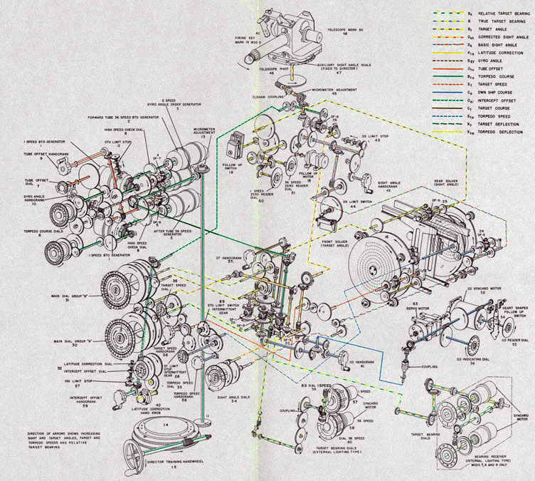
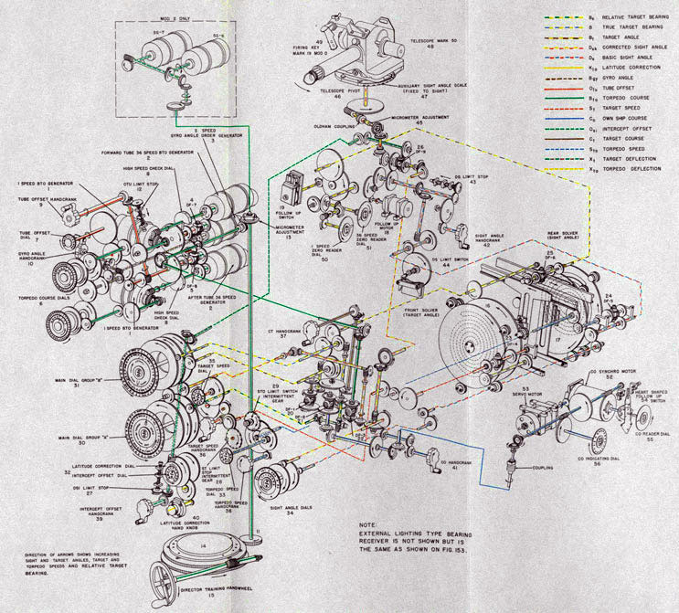
ELEMENT NUMBERS
Transmitter
1. Synchro generator, 1-speed, type 5G
2. Synchro generator, 36-speed, type 5G
3. Synchro generator, 2-speed, type 5G
4. Differential, DF-7, Otu
5. Differential, DF-8, Otu
6. Dial, 2-speed, Bto, Bgy
7. Dial, 4 1/2 speed, Otu
8. Dial, check, 36-speed
9. Hand crank, Otu
10. Hand crank, Bgy
11. Back Post, Bto2
12. Stop, Otu 13. Micrometer adjustment
Training Circle and Stop
14. Training circle and stop
15. Handwheel, Director Train
Computer
16. Angle-solver, front
17. Angle-solver, back
18. Follow-up motor, sight angle
19. Follow-up switch
20. Differential, DF-1, Bt
21. Differential, DF-2, Co
22. Differential, DF-3, Bto
23. Differential, DF-4, St
24. Differential, DF-5, Sto
25. Differential, DF-6, Xt
26. Differential, DF-9, Dsk
27. Stop, Osi
28. Stop, St
29. Stop, Sto
30. Dial, 1-speed, Bs, B, Dsk
31. Dial, 1-speed, B, Bt, Dsk
32. Dial, 6-speed, KIa, Osi
33. Dial, 1 turn 60 knots, Sto
34. Dial, 1-speed, Ds, Dsk
35. Dial, 1 turn 60 knots, St
36. Hand crank, St
37. Hand crank, Ct
38. Hand crank, Sto
39. Hand crank, Osi
40. Hand crank, Kla
41. Hand crank, Co
42. Hand crank, Ds
43. Stop, Ds
44. Switch, contact arm, Os
45. Micrometer adjustment
46. Telescope Pivot
47. Scale, auxiliary sight angle
48. Telescope, Mk 50 Mod 0
49. Firing key, Mk 19 Mod 0
50. Dial, 1-speed-zero reader
51. Dial, 36-speed-zero reader
Own Ship Course
52. Synchro motor, type 5B
53. Servo motor, 115-volt AC
54. Heart-shaped follow-up switch
55. Dial, zero reader, Co
56. Dial, 1-speed, indicating, Co
Bearing Receiver
57. Synchro motor, 1-speed, type 1F
58. Synchro motor, 36-speed, type 1F
59. Dial, 1-speed, Bs
60. Dial, 36-speed, Bs
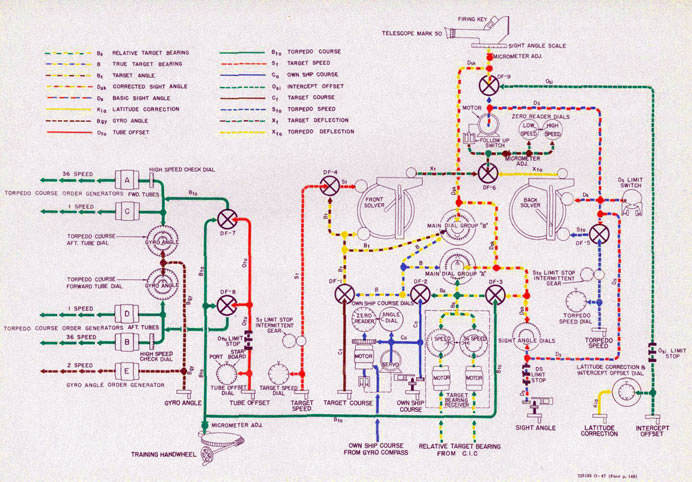
Figure 146-Functional diagram showing course of inputs and outputs through the Torpedo Director Mk 27 Mods 1,3,4,5,7,8 and 9.
OPERATION ROUTINE
This section will outline a suggested operation routine for putting the
torpedo director into
operating condition. This routine may vary somewhat with different ships
depending upon ship's
doctrine. In the following outline, the encircled numbers refer to the
various hand cranks that
are shown on figure 147.
1. After removing the tarpaulin cover, set in latitude correction, each morning, by turning the latitude correction knob (1). This can
be done by the officer
with the morning watch.
2. Turn on the power supply to the director and the torpedo control system
at the fire control
switchboard. Also, turn on the director heater supply.
3. Turn the bridge transfer switch to "PORT" or "STARBOARD".
4. Turn the director selector switch to "ON" and illumination switch to
"TRANSFORMER".
The torpedo director is now ready to track a target. In setting up a
problem on the torpedo
director, the following procedure is suggested:
1. Train the director on the target by turning the training handwheel (2)
to match the dials of
the bearing receiver or to bring the telescope sight to bear on the target.
2. Set the sight angle crank (3) and the own ship course hand crank (4) to
"OUT" position.
NOTE: In case of power failure, these hand cranks should be left in the
"IN" position. As the
problem progresses, the own ship course hand crank must be turned to keep
the zero reader dial
at "0", and the sight angle hand crank must be turned to keep the high- and
low-speed reader
dials matched at "0".
3. Introduce tube offset by turning the tube offset crank (5).
4. Introduce refined latitude correction by turning the knob (1) to correct
for torpedo creep.
5. Match the intercept offset dial, with the reading on the latitude
correction dial by turning
hand crank (6). Set intercept offset as necessary to correct for torpedo
turning circle when
firing shots with large gyro angles.
6. Crank in torpedo speed by turning the torpedo speed hand crank (7).
7. Introduce gyro angle, as directed by the torpedo control officer, by
turning the gyro angle
crank (8).
8. Introduce target speed by turning the target speed hand crank (9).
9. Set target course into the director by turning the target course hand
crank (10). Then train
director on target using the telescope sight pr by matching the dials of
the bearing receiver.
10. Fire the torpedoes, as directed, by closing the firing key (11).
The following procedure is suggested for securing the torpedo director:
1. Train the torpedo director to its stowed position, relative bearing "0 ".
2. Set all the dials of the torpedo director to zero by turning the various
hand cranks.
3. Turn the director selector switch and the illumination switch to "OFF".
4. Turn the bridge transfer switch and the heater switch to "OFF".
5. Turn off the power to the torpedo director at fire control switchboard.
6. Cover the torpedo director with tarpaulin provided.
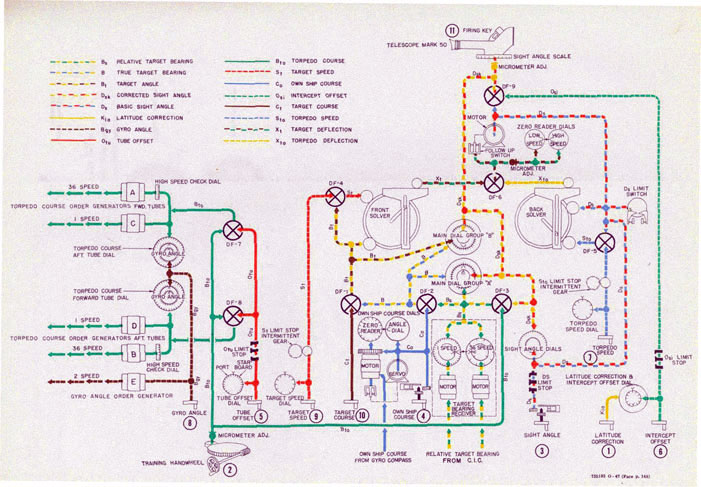
Figure 147-Diagram of suggested operation routine.
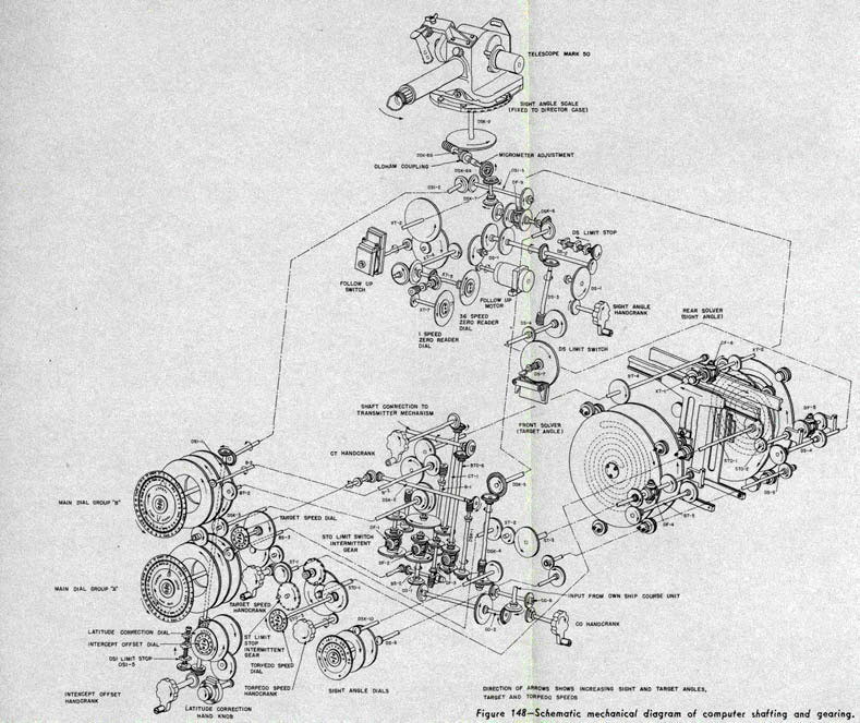
Figure 148-Schematic mechanical diagram of computer shafting and gearing.
Figure 149-Mechanical diagram of Torpedo Director Mk 27 Mods 1, 3, 4, 5, 7, 8 and 9.
Figure 150-Mechanical diagram of Torpedo Director Mk 27 Mod 2.
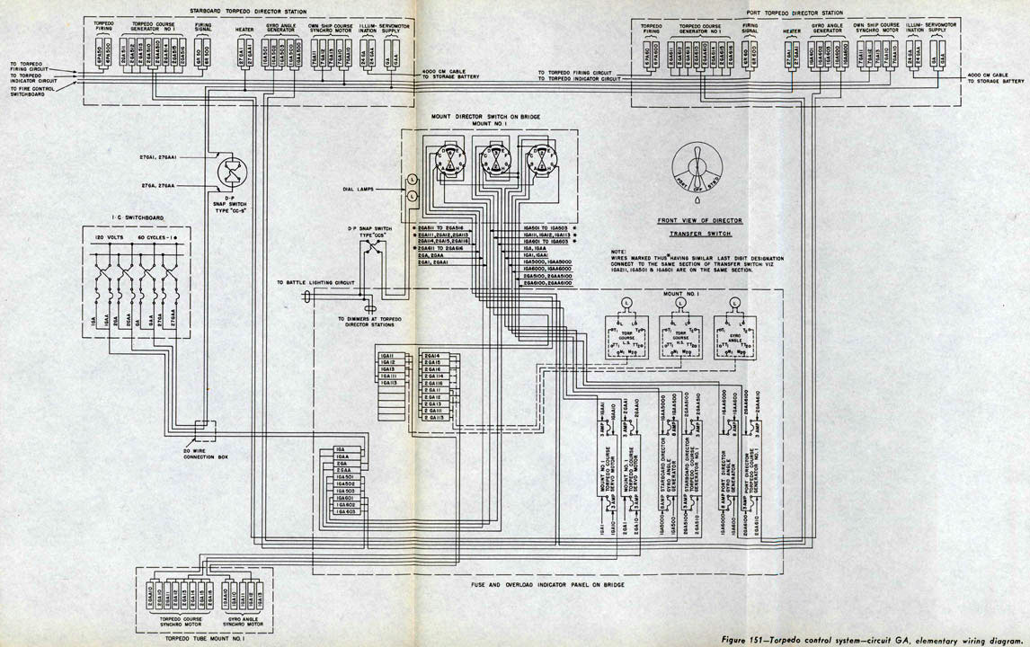
Figure 151-Torpedo control system-circuit GA, elementary wiring diagram.
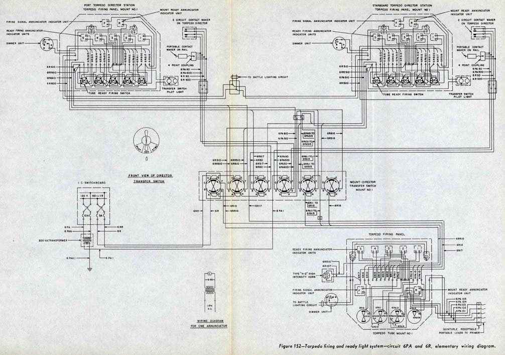
Figure 152-Torpedo firing and ready light system-circuit 6PA and 6R, elementary wiring diagram.
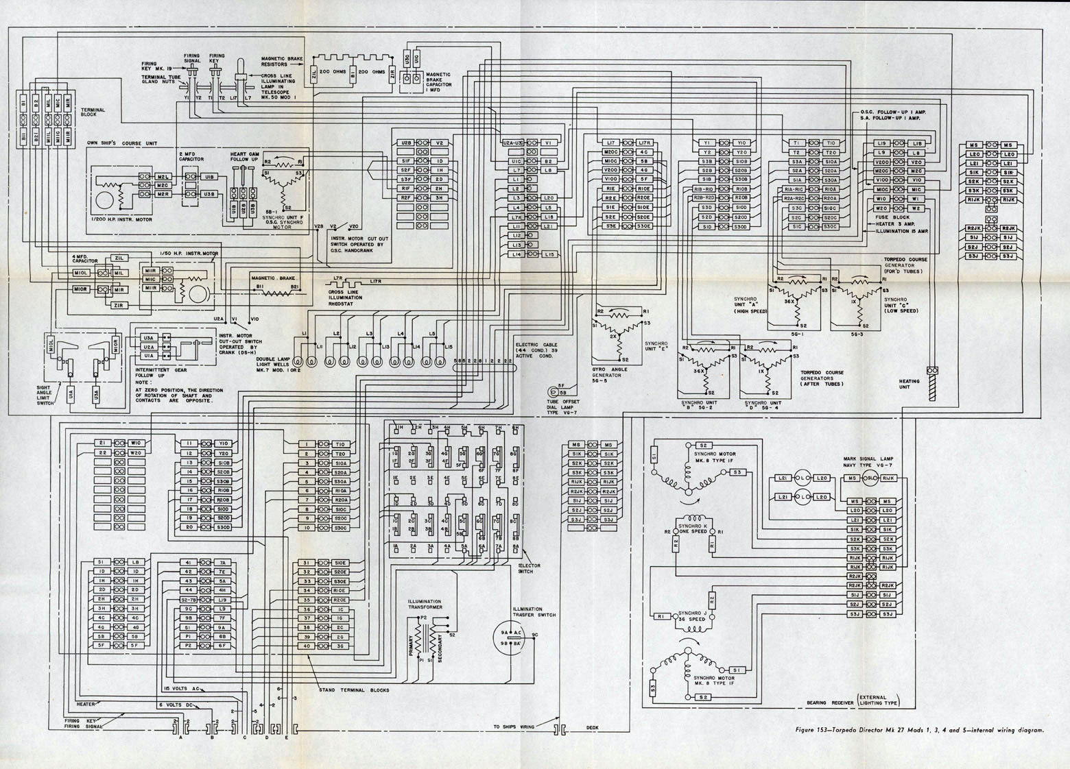
Figure 153-Torpedo Director Mk 27 Mods 1,2,3,4 and 5-internal wiring diagram.
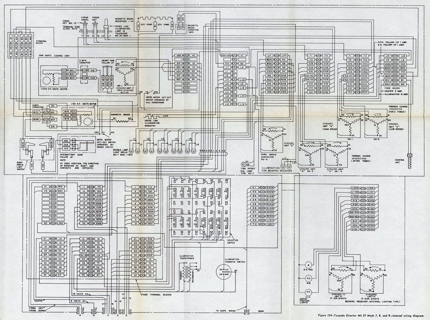
Figure 154-Torpedo Director Mk 27 Mods 7,8, and 9-internal wiring diagram.
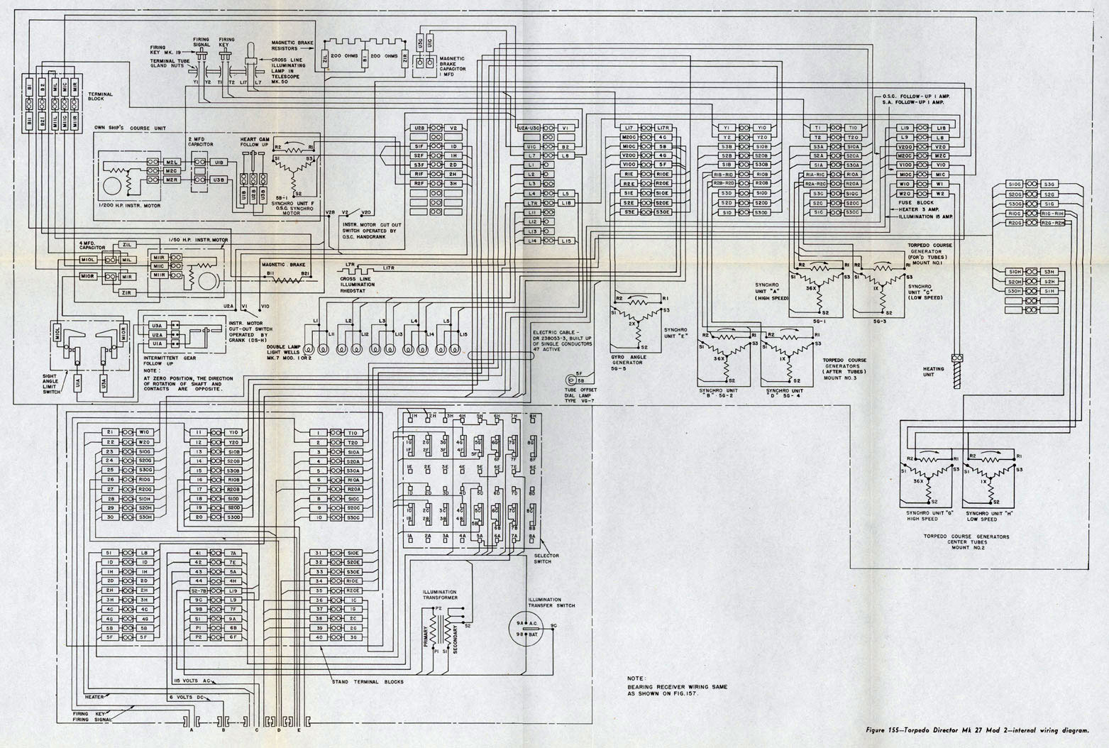
Figure 155-Torpedo Director Mk 27 Mod 2-interal wiring diagram.
DISTRIBUTION
Requests for additional copies of OP 1586 should be submitted on NAVGEN 47, Stock Forms and
Publications Requisition, through the District Publications and Printing Office by which
addressee is serviced. Mailing addresses should be obtained from List 1O.VV of the Standard Navy
Distribution List.
DISTRIBUTION:
Standard Navy Distribution List No. 46 (Part 1) and Edition No. 4 (Part 2) to Catalog of Activities of the wavy.
1 copy unless otherwise noted.
1. A, E, H, L, M; 2. G, I, S; 3. (2 copies), X; 3. (5 copies), Z; 6. A; 7. (5 copies), A*; 8. (5
copies), T-6O, T-34, T_35*, T-36; 10. (25 copies,) VV; 11.(CNO, BuOrd*)