|
PART V
REPAIR
501. GENERAL.
(a) For the purpose of periodic maintenance, service and repair, Major ECM
Repair Facilities,
Intermediate ECM Repair Facilities, and Minor ECM Repair Facilities have
been established at
the following locations:
|
MAJOR ECM REPAIR FACILITIES
Naval Code and Signal Laboratory, Washington, D.C.
Navy Yard New York
Navy Yard Mare Island
Navy Yard Puget Sound
Navy Yard Pearl Harbor
Naval Operating Base Oran
Naval Operating Base Noumea
Naval Operating Base Londonderry
Naval Operating Base Adak
Convoy Escort Base Milne Bay
INTERMEDIATE ECM REPAIR FACILITIES
Navy Yard Boston
Navy Yard Norfolk
Repair Base San Diego
U.S. Naval Drydocks San Pedro
COM 7 - Miami (RMO)
COM 15 - Balboa (RMO)
|
MINOR ECM REPAIR FACILITIES
Navy Yard Charleston
Navy Yard Philadelphia
Navy Yard Portsmouth, N.H.
Naval Station Coco Solo
Naval Station New Orleans
Naval Operating Base Dutch Harbor
Naval Operating Base Key West
Naval Operating Base Kodiak
Naval Operating Base Newport
Naval Operating Base Norfolk
Naval Operating Base San Juan
Naval Operating Base Sydney
Naval Operating Base Argentia
Naval Operating Base Bermuda
Naval Operating Base Guantanamo
Naval Operating Base Trinidad
Naval Operating Facility
Naval Camp Parera Curacao
Submarine Base Midway
Submarine Base New London
U.S. Coast Guard Yard Curtis Bay, Md.
ASS'T. NAVINDMAN San Francisco
COM 12 San Francisco (Comm. Off.)
COMAIRSOPAC Espiritu Santo (Comm. Off.)
COMNAVEU London (Comm. Off.)
|
|
SHIPS
USS AJAX
USS ALCOR
USS ALTAIR
USS ARGONNE
USS BEAVER
USS BLACK HAWK
USS BRIAREUS
USS BUSHNELL
USS CASCADE
USS DELTA
USS DENEBOLA
USS DIXIE
USS DOBBIN
USS EURYALE
USS FULTON
USS GRIFFIN
USS HAMUL
USS HOLLAND
|
USS MARKAB
USS MAUMEE
USS MEDUSA
USS MELVILLE
USS ORION
USS OTUS
USS PATOKA
USS PELIAS
USS PIEDMONT
USS PRAIRIE
USS PROMETHEUS
USS PROTEUS
USS RIGEL
USS SPERRY
USS VESTAL
USS VULCAN
USS WHITNEY
|
|
| |
-46-
|
(b) ECM Repair Facilities are divided into four classes as follows:
|
(1) Major ECM Repair Facilities, which stock a large quantity of all spare
parts available for
distribution to other repair activities and are staffed and equipped to
make any repair on all
types of cryptographic devices used by the Navy.
(2) Intermediate ECM Repair Facilities, which stock a smaller quantity (40%
of a Major
Facility stock) of all spare parts available for distribution to Minor
Repair Activities and are
staffed and equipped to do general overhaul and repair work on all types of
Naval cryptographic
equipment.
(3) Minor ECM Repair Facilities, which have a stock of the more vulnerable
parts of the equipment and are staffed and equipped to make inspection and repairs of a minor
nature on all Naval
cryptographic devices.
(4) Emergency Minor ECM Repair Facilities, which also have a stock of the
more vulnerable,
parts of the equipment. The parts are supplied to these activities because
of the number of
cryptographic devices in use at the activity or because of their geographic
isolation from an
authorized repair facility. They are not staffed or equipped to render
inspection or maintenance
service on other than their own equipment except in an emergency.
|
(c) Each repair facility with the exception of the Emergency Minor ECM
Repair Facility is
prepared for periodic overhaul of the ECM, and insofar as possible, has
been provided spare
machines in order that a ship can exchange its machine for a thoroughly
re-conditioned
machine.
(d) The above ECM Repair Facilities are provided with the "Repair and
Maintenance
Instructions", Blueprints, Parts Catalogs, etc. and service personnel
attached thereto have
attended a course of instruction at an ECM training school.
502. TRAINING SCHOOLS.
(a) Schools for the instruction and training of personnel in the repair and
maintenance of
cryptographic machines are maintained at each of the Major ECM Repair
Facilities. Instruction
of three weeks duration is given for the purpose of training personnel
attached to an individual
activity in the technique of cleaning, oiling and performing emergency
repairs, utilizing the
Spare Parts Box (ENG 109) supplied with each ECM. Two or three day
"appreciation" courses
are available for communicators to familiarize them with the general
mechanical operation,
oiling and cleaning of the ECM.
(b) Commanding officers are urged to nominate trustworthy personnel for
these schools.
Arrangements should be made by directly contacting the Major Repair
Facility.
(c) In addition to the Major ECM Repair Facilities, schools are located at
the following points:
ECM Repair Facility, Boston
ECM Repair Facility, Norfolk
|
|
| |
-47-
|
|
503. QUALIFIED AND AUTHORIZED REPAIR PERSONNEL.
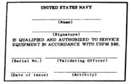
(a) Personnel who satisfactorily complete the full course at an ECM
training school are issued
the card illustrated below. Personnel from a repair facility should be
required to present this
card and the standard Navy Identification Card before being allowed to
service the machine.
Holders of qualification cards who are not assigned to duty at authorized
ECM Repair Facilities
are normally authorized to perform only routine cleaning, oiling and
emergency repairs to the
extent of the tools and parts available in the ENG 109. The services of the
personnel at
established ECM Repair Facilities should be utilized to the greatest
practicable extent for
monthly inspections and major overhaul. Unsatisfactory performance of
duties by any card
holder should be reported to the Bureau of Ships, Code 945.
504. EMERGENCY REPAIRS.
(a) When the ECM requires attention, either for routine inspection,
emergency repairs,
overhaul, adjustment, etc., service should be requested from the nearest
ECM repair facility.
Experience has shown that cryptographic machines have suffered more from
attempted repairs
by inexperienced personnel than from wear and tear, therefore, routine
tests and overhauls
should be undertaken only by experienced personnel.
(b) It is realized that in many cases the above procedure is not a
satisfactory solution to an
immediate problem and emergency repairs will have to be effected, if at all
possible. The
emergency repair instructions given herein are written for the individual
who has not had a
course of instruction, therefore, they contain no information on adjustment
tolerances, repairs
requiring special tools, etc. Any emergency repairs effected should be
rechecked as soon as
practicable in an ECM repair facility.
(c) The effecting of emergency repairs is chiefly a matter of common sense.
The decision is the
responsibility of the Commanding Officer. For example, with tender
facilities available, it
would be undesirable to subject the machine to possible mistreatment at the
hands of
inexperienced personnel. On the other hand, if the machine breaks down
while at sea, the ship's
force should attempt any repair considered to be within its capabilities,
even at the risk of
further damage. Reasonable effort must be made to keep the machine in
operation.
505. SPARE PARTS BOX (ENG 109).
(a) A Spare Parts Box (ENG 109) has been issued to each activity holding
the ECM. The parts
included are those required for repairs and maintenance normally considered
to be within the
capabilities of the ship's force.
|
| |
-48-
|
(b) The contents of the Spare Parts Box (ENG 109) has been revised from
time to time. Each
Spare Parts Box currently contains the following items:
| Part No. |
Description |
QTY. |
| 4840 |
Double end wrench |
1 |
| 70169 |
Hand tape moistener |
1 |
| 72755 |
Wick for Hand tape moistener |
1 |
| 75765 |
Spring hook - pull |
1 |
| 76084 |
Friction disc - felt |
6 |
| 76280 |
Capstan wrench |
2 |
| 82285 |
Resistor, 300 ohm |
1 |
| 88265 |
Retaining Bushing |
12 |
| 88448 |
Plunger contact assembly |
12 |
| 88993 |
Contact burnisher |
1 |
| 91755 |
Power switch |
1 |
| 100013 |
Print hammer |
1 |
| 100076 |
Type wheel |
1 |
| 100121 |
Print hammer insert - rubber |
6 |
| 100129 |
Friction clutch washer |
5 |
| 100141 |
Tape feed pawl |
1 |
| 100212 |
Clutch throwout lever |
1 |
| 100260 |
Stepping magnet |
1 |
| 100600 |
Unwired code wheel |
1 |
| 100645 |
Capacitor - 2 mfd. |
1 |
| 100646 |
Capacitor - 1 mfd. |
1 |
| 100648 |
Resistor - 100 ohms |
1 |
| 100649 |
Fuse - 5 amp |
5 |
| 100688 |
One drop Oiler |
1 |
| 100709 |
Wrench set - Williams |
1 |
| 100895 |
ENG 109 Container - metal |
1 |
| 100919 |
Fuse - 10 amp |
5 |
| 100945 |
Wire #20, 15-foot roll |
1 |
| 100972 |
Clutch spring |
1 |
| 100973 |
Cleaning block (with canvass) |
1 |
| 100978 |
Canvass belt for cleaning block |
1 |
| 100982 |
Screwdriver - 6 inch |
1 |
| 100983 |
Oil - 8 oz. can |
1 |
| 100984 |
Grease - 2 oz. tube |
1 |
| 108095 |
Nut, 4-40 |
6 |
| 108101 |
Screw 4-40 flat head |
6 |
| 108102 |
Screw |
3 |
| 108261 |
Plunger tool |
1 |
| 108663 |
Contact spring |
1 |
| 110426 |
Clutch magnet complete (old number M-222) |
1 |
| 110437 |
Spring (old number 35-70) |
1 |
|
| |
-49-
|
|
EMERGENCY REPAIRS
506. ZEROIZING.
(a) Condition: Code Wheels will not zeroize.
(b) Probable cause:
|
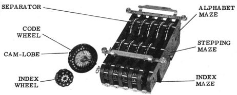
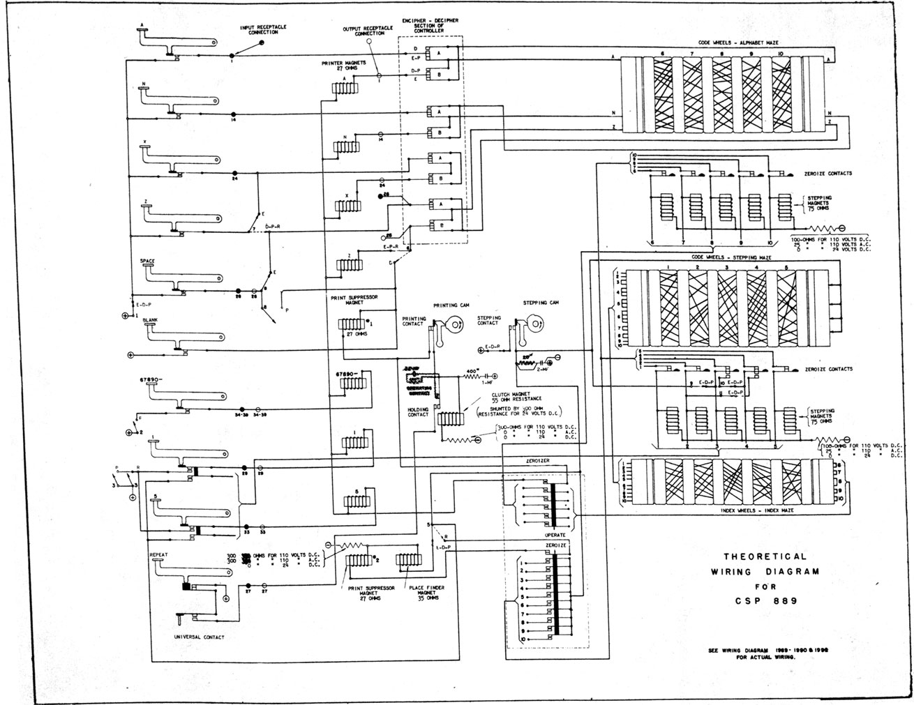
(1) The zeroizing springs are bent out of adjustment. The cam-lobes (see
plate BA) are so situated that, when the Code Wheel is aligned to "O", the spring contact of the
zeroizing contact will
be shifted to open the circuit. Bend the zeroizing spring of the faulty
Code Wheel position back
into shape, using the others as a guide. Turn the Code Wheel by hand and
observe the action of
the cam-lobe against the spring contact until the cam-lobe opens the spring
contact.
NOTE: If any of the Code Wheels EXCEPT the center Code Wheel of the
Stepping Maze and the one
immediately to its right (#3 and #4) fail to zeroize, they may be zeroized
by hand. If #3 and
#4 Code Wheels of the Stepping Maze will not zeroize DO NOT USE THE MACHINE
UNTIL CORRECTED.
|
507. CODE WHEELS OF STEPPING MAZE.
(a) Condition: None of the Code Wheels of the Stepping Maze step.
(b) Probable cause:
|
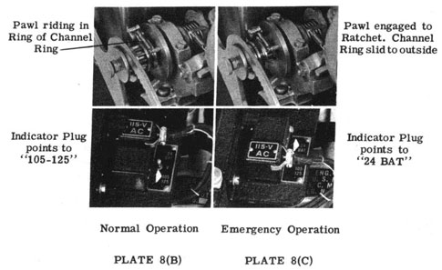
(1) The Stepping Timing Contact may be dirty or out of adjustment (See
Plate 6). When the
main shaft is at rest, this contact is held open, but is closed immediately
alter the main shaft
commences to turn. Shift to emergency hand power operation (para. 325) and
slowly turn the
main shaft and observe the action of this contact. Clean the contact and if
necessary bend the
spring so it will make contact properly.
|
508. CODE WHEELS OF ALPHABET MAZE.
(a) Condition: None of the Code Wheels of the Alphabet Maze will step.
(b) Probable cause:
|
(1) A Code Wheel or Index Wheel may be turned "half way" so that the
circuits are not
completed.
|
509. KEYLEVER FAILURE.
(a) Condition: All of the Keylevers are inoperative.
(b) Probable causes:
|
(1) The Print Timing Contact (See Plate 6) may not be making contact. When
the main shaft is
at rest, this contact is closed, but opens immediately alter the main shaft
commences to turn.
Clean the contact and if necessary bend the contact spring so the contact
is closed in the normal
unoperated position of the main shaft.
(2) The Clutch Magnet circuit may be open. Examine the connections from the
magnet winding
to the solder lugs.
(3) The spring attached to the clutch stop lever above the casting on the
right hand end of the
main shaft may have come off the spring post. Replace the spring.
|
|
| |
-50-
|
|
(c) Condition: A single Keylever fails to print on "P" (Plain).
(d) Probable causes:
|
(1) A Printer magnet may be shorted or burned out or the circuit may be
broken, 1.1 a Printer
Magnet becomes shorted, the printing associated with that magnet will be
smudged, but
otherwise the operation of the machine is unchanged. if a printer magnet
circuit is open, the
machine will fail to operate each time a keylever is pressed which should
result in the
energizing of that magnet. The Printer should not be opened because special
tools are required
for re-assembly. The best practice to follow in case of an opened printer
magnet or circuit is to
type slowly, making sure each Keylever depressed operates the Printer. When
the depressing of
a key fails to operate the Printer, press the "Blank Key". This will
produce a blank on the tape
which will have to be filled in later, but the machine will be in step for
succeeding letters. The
letter to be filled in is determined by the letter failing to print when
typing plain.
(2) On encipherment or decipherment the failure of a letter to print (when
all letters print
properly on plain) almost always is caused by a contact failure through the
Alphabet Maze.
Clean the contacts. Examine the Code Wheels for bad connections. Hold the
Keylever down and
"wiggle" the Code Wheels. The best practice is to press the Blank Key or
another Key which will
produce a one-letter garble which ordinarily is capable of being cleared by
inspection.
(3) A Controller contact may be operating improperly.
|
510. MOTOR FAILURE.
(a) Condition: The motor fails to start.
(b) Probable causes:
|
(1) Fuses, are burned out. Unscrew the fuse holder and remove the fuses.
Replace the fuses
with new fuses and replace the holder.
NOTE: If a fuse "sticks" in the holder, remove the cover (two screws in
front, one at each side
and one in the rear, inside the case). Take a small stiff wire and punch
the fuse out by inserting
the end of the wire through the hole in the solder lug at the bottom of the
fuse-holder.
(2) The switch which controls the motor is located on a bracket attached to
the top of the
Controller and is turned on and off by a mechanical link to the Controller
shaft. Check the
relative position of the switch to insure that it is actually snapped when
the Controller handle is
turned away from "O" (Off).
|
511. 26-30 LETTER CHECK.
(a) Condition; The 26-30 Letter Check is not produced.
(b) Probable cause:
|
(1) Try the Stepping Check of para. 308 and observe the stepping of the
Code Wheels of the
Stepping Maze. The zeroizing contacts of the #3 and #4 Code Wheels have an
additional contact
spring for the purpose of producing the automatic stepping of the Code
Wheels. (See para.
203(d) for Stepping Control). When the cam-lobe of the Code Wheel engages
the contact spring,
it should be held away from the contact spring nearest the Code Wheel and
should be in contact
with the spring nearest the front of the machine.
|
|
| |
-51-
|
|
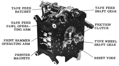
512. PRINTING.
(a) Condition; Printing on the tape is smudged, or indistinct.
(b) Probable causes:
(1) The type wheel is turned by a friction clutch composed of two felt
washers separated by the
drive gear and retained by a flange of the printer shaft on the forward
side and a friction disc at
the rear. Should this assembly become loose, or the friction washers worn,
the type wheel will
not be turned fast enough or will not be held motionless during the
printing of a character. Part
No. 76084 is the replacement part. Part No. 76280 Is the Capstan wrench for
use with the
printer. To replace the friction washers:
|
(A) Disconnect the power from the machine and remove the Cipher Unit.
Remove the cover (two
securing screws are located on the front at the sides of the cover and one
is located inside the
cover at the rear). Engage the hand drive, manually trip the clutch and
rotate the main-shaft
until the stepping drive bars have reached their maximum forward travel.
Remove the bracket
from the right top of the printer and disconnect the two Jones receptacles
at the top left of the
printer. Remove the two screws through the rear feet of the printer and
remove the two nuts
from the studs through the front feet of the printer. Raise the printer
until the front feet clear
the studs and withdraw the printer from the machine.
(B) Using a 3/4 inch wrench and the Capstan wrench, remove the locking nut
and spring seat
from the rear end of the printer shaft. Remove the friction disc and felt
washer, the drive gear
and front felt washer, and replace with new washers which have been
saturated with light oil.
(C) Reassemble in reverse order. When replacing the drive gear on the
printer shaft the recess
in the gear should face away from the printer so that the recess will hold
the rear friction
washer centrally with respect to the shaft and away from the threads of the
shaft.
(D) Re-install the printer. Hold the printer so the print hammer follower
and feed pawl
followers are in line with their associated cams, and so the holes in the
front feet are in line
with the mounting studs. Lower the printer carefully, making sure that the
feed shift lever and
keeper straddle the feed shift arm. Take up the play of the printer toward
the rear and to the
right and tighten the printer mounting screws and nuts. Insert the printer
receptacles and
fasten the retainer arm. Re-fasten the bracket to the right top of the
printer.
(E) Manually trip the clutch and slowly turn the main shaft several times
and observe that all
mechanical action takes place smoothly.
(F) Connect the machine to power. Set the Controller at "P" (Plain) and the
Zeroizer to
"Operate". Depress any key. Tighten the spring seat until the printing on
the tape becomes
legible.
|
(2) if the "M" and "W" are not distinctly printed at the outer edges, it
may be that the Print
hammer insert is not wide enough on the striking surface. Replace with a
new insert. If only one
side of the letter is printed, make the adjustment of the following
paragraph.
(3) if the typewheel is broken or no longer serviceable and is to be
replaced, remove the three
screws which hold it to the typewheel shaft. Remove the damaged typewheel
and replace it with a
new one, reinstalling the screws. The screw holes are so placed that the
typewheel will fit only
one way. Barely tighten the three screws and alternately type "M" and "W".
If necessary, loosen
the screws, shift the typewheel in the proper direction and retighten the
screws. (Caution:
Don't twist the screws off.)
(4) if the letters tend to print one on top of another, it may be the paper
tape is not free to
unwind, properly. The tape retainer may be bent causing undue pressure
against the paper roll.
The tape feed rollers may not mesh properly or may not have sufficient
tension to advance the
tape.
(5) A tendency for the paper roll to unwind too fast may be overcome by
slightly bending a section
of the tape retainer.
|
|
| |
-52-
|
|
513. SPARK SUPPRESSORS.
(a) Condition: Excessive sparking at the timing (Stepping and Printing)
contacts at the main
shaft.
(b) Probable cause: Excessive spark at the timing contact (Printing) may be
caused by failure
of the spark suppressor circuit which is composed of a resistor, 400 ohms,
and a capacitor, 1 mfd., located to the rear of the keylevers. The capacitor of the timing contact (Printing) is the one located next to the base. To test for failure see para. (e).
(c) Excessive sparking at the timing contact (Stepping) may be caused by
failure of the spark
suppressor circuit which is composed of a capacitor, 2 mfd., located on top
of the one mfd. capacitor referred to in part (b) above. To test for failure see part (e).
(d) To test the resistor, measure the resistance with an ohmmeter.
(e) To test the capacitor:
|
(1) Disconnect the power lead from the source of power.
(2) Disconnect the brown wire from the clutch magnet. Using a 50,000
ohmmeter touch both
terminals of the 1 mfd. capacitor and watch the pointer of the ohmmeter.
There should be a
momentary deflection of the pointer alter which it should rest at infinite
ohms. Reverse the
leads of the ohmmeter and repeat the operation. If there is not a momentary
deflection of the
pointer of the ohmmeter or if the pointer does not rest at infinite ohms
the capacitor should be
changed. Disconnect the terminals of the 2 add. capacitor and test it in
the same manner. Replace
all leads.
|
(f) It is realized the above test is not a conclusive test, and is given
only because an ohmmeter
is generally available, whereas a capacitor tester generally is not. If a
capacitor tester is
available, it should be used to test the capacitor in lieu of the above
tests.
514. CODE WHEELS.
(a) Condition: Code Wheel contacts badly pitted or worn, path between
contacts indicates
sparking between contacts has occurred.
(b) Probable cause:
|
(1) Any of the above conditions may be caused by failure of the spark
suppressors circuit of the
Printing Contact of the main shaft. See para. 513(b).
|
(c) If a Code Wheel is defective, the best procedure is to exchange the
defective set for another
set at the nearest Issuing Office which in turn will send the defective set
to the nearest ECM
Repair Facility for repair. The defective set of Code Wheels should be
suitably tagged, indicating
the defective Code Wheel, and in such a manner that the defective set will
not accidentally be
issued before being repaired. If the set cannot be exchanged, the Code
Wheel should be repaired
locally.
(d) To repair a Code Wheel:
|
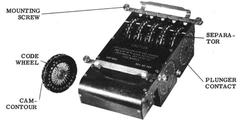
(1) Make a diagram of the wiring, and, if a cam-contoured Code Wheel, the
cam-contours.
NOTE: These diagrams shall be classified TOP SECRET, and shall be placed in
the custody of a
commissioned officer. The diagrams shall be destroyed immediately alter a
successful test of the
repaired Code Wheel.
(2) Unsolder the wires from the solder lugs of the defective face. As much
as possible keep them
in their relative positions.
(3) Remove the four screws from the face and lift the defective face from
the Code Wheel.
Remove the corresponding face from an unwired Code Wheel (Part No. 100600
In the Spare
Parts Box) and place it on the Code Wheel, making sure that the cam-lobe of
the unengraved face
is opposite "H" and "I" of the engraved face.
|
|
| |
-53-
|
|
(4) Resolder the wires.
(5) For cam-contoured Code Wheels, the cam-contours must be added, it is
necessary that these
be accurately placed. Mark on the Code Wheel the points at which
cam-contours are to be added.
Cam-contours can be filed into the face with a circular file.
(6) Test the Code Wheel by making several different 26-30 Letter Checks.
(For cam-contoured
Code Wheels choose Code Wheel Arrangements utilizing the repaired Code
Wheel in the center
(#3) position).
(7) if both faces must be replaced it is better to repeat the operations
for the second face rather
than to Individually unsolder each wire from the defective Code Wheel and
resolder it on the new
one.
|
(e) Obtain another spare Code Wheel for the Spare Parts Box by ordering it
from the most
convenient ECM Repair Facility.
515. MOTOR ADJUSTMENT.
(a) The Condition: Machine runs sluggishly, the motor labors, the hand
drive operates with
difficulty.
(b) Probable cause:
|
(1) The mesh of the motor pinion and the main shaft drive gear is "too
close". The best method
of adjustment is to shift to hand drive operation. Adjust the motor
adjusting screw until effort
is required to turn the main shaft, then back off slightly.
|
516. CLUTCH MAGNET.
(a) A spare clutch magnet is included in the Spare Parts Box, but
replacement should not be
attempted unless the operator has had training in the replacement. The
adjustments required in
making a replacement require certain tolerances, some of which are rather
critical and unless
the operator has been trained and the proper tools are available, it is
very difficult to make a
repair.
517. RECHECKS REQUIRED.
(a) It is emphasized that the repair operations given in this part are for
reference only in the
event emergency repairs are required and the services of an ECM Repair
Facility are not
available. In each instance of an emergency repair, it should be re-checked
at the first available
opportunity by an ECM Repair Facility.
518. ADJUSTMENT SPECIFICATIONS.
(a) The following tabulation of adjustment specifications is provided for
the convenience of
repair personnel. It is to be used only by qualified ECM repairmen (holders
of CSPM 390
qualification cards - see para. 503).
|
| |
-54-
|
|
ADJUSTMENTS |
| ASSEMBLY PARTS INVOLVED |
Min. |
Max. |
Type* |
| Keylever Contacts |
| Universal Bar and Keylevers |
.050 |
.075 |
Clearance |
| All Contacts, less "RPT" and 1-5 outer |
.040 |
.050 |
Gap |
| 1-5 Keylever outer Contacts |
.020 |
.030 |
Gap |
| "RPT" Keylever Contact |
.010 |
.020 |
Clearance |
| Universal Contact |
.015 |
.025 |
Gap |
| Clutch Contacts |
| Inner Contact |
.015 |
.025 |
Gap |
| Outer Contact |
.025 |
.040 |
Gap |
| Roller and Contact Spring |
.025 |
.045 |
Clearance |
| Clutch Mechanism |
| Armature and Field Yoke |
.010 |
.020 |
Clearance |
| Armature Lever Latching Extension and Clutch Stop Lever Latching Extension (stop position) (old) |
.006 |
.010 |
Clearance |
| Armature Lever Latching Extension and Clutch Stop Lever Latching Extension (reset position) (old) |
.015 |
.025 |
Clearance |
| Armature Lever Latching Extension and Non-Repeat Latch (stop position) (New) |
.002 |
.006 |
Clearance |
| Armature Lever Latching Extension and Clutch Stop Lever Latching Extension (reset position) (New) |
.004 |
.010 |
Clearance |
| Clutch Throwout Lever Extension and Clutch Stop Lever Adjustment Screw |
.004 |
.010 |
Clearance |
| Main Shaft |
| Clutch teeth |
.020 |
.035 |
Clearance |
| Channel cam and Stepping Bell Crank Roller |
.006 |
--- |
Clearance |
| Timing Contacts |
| Print Contact only (old) |
.005 |
.015 |
Clearance |
| Stepping Contact only (Old) |
.030 |
.045 |
Gap |
| Both Contacts (New) |
.006 |
.015 |
Clearance |
| Both Contacts (New) |
.015 |
.025 |
Gap |
| Stepping Magnets, Drive Bars and Pawls |
| Armature and Armature Back-Stop |
.050 |
.060 |
Clearance |
| Armature and Stepping Pawl Latch Adjusting Screw |
--- |
.006 |
Clearance |
| Stepping Pawl, latching clearance |
.030 |
.045 |
Clearance |
| Zeroize Contacts |
| Contact Springs of #3 and #4 Zeroise} |
.035 |
.050 |
Clearance |
| Contacts (Stepping) and Code Wheel} |
.015 |
.025 |
Gap |
| Printer Tape Feed Mechanism |
| Tape Feed Pawl and Ratchet, Controller at "R" |
.015 |
.025 |
Clearance |
| Tape Feed Pawl and Ratchet, Controller at "E" |
.010 |
--- |
Clearance |
| Tape Feed Pawl and Ratchet, Controller at "R" |
.010 |
--- |
Clearance |
| Torque - Tape Feed Shaft |
10 to 12 oz. Torque |
|
|
| |
-55-
|
|
ADJUSTMENTS |
| ASSEMBLY PARTS INVOLVED |
Min. |
Max. |
Type |
| Printer Stop Pins |
| Stop Pin and Stop Pin Latch |
1/64" |
--- |
Clearance |
| Typewheel |
| Torque - Typewheel Shaft |
14 to 17 oz. Torque |
| CSP 1600 |
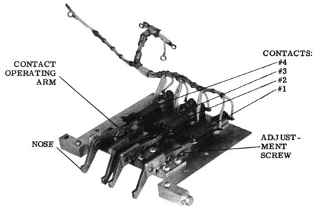
| Contact Operating Arm |
| Contact operating arm and bottom of cam-contour |
.020 |
--- |
Clearance |
| Stepping Contacts |
| Contact operating arm and contact spring |
.006 |
.010 |
Clearance |
| Contacts |
.015 |
.020 |
Gap |
519. STEPPING CHECKS.
(a) The following chart provides a means of checking the operation of the
machine through the
first ten-thousand (10,000) steps from the zeroize position.
(b) To make the Stepping Check
(1) Using CSP 1336 (ECM Code Wheel Set C31 to C4¯), arrange the Code Wheels
according to
the following Arrangement
Alphabet Maze: 31-32-33-34-35 (All Code Wheels normal,
Stepping Maze: 36-37-38-39-40 (none reversed.
|
(2) Set the Index Wheels to the following Index Wheel Setting:
(3) Zeroize.
(4) Set the Controller at "E" (Encipher), and the Zeroizer to "Operate".
(5) Withdraw the paper tape, and reset the Counter to zero.
(6) Using the "Blank" Key, step the Code Wheels, comparing the Alignment of
the Code Wheels
at the step numbers listed on the chart.
|
|
| |
-56-
|
|
STEPPING CHECK TABLE
CODE WHEEL SETTINGS
| Code Wheel Set CSP 1336 (C31-C40) |
| Alphabet Maze: |
31 |
32 |
33 |
34 |
35 |
| Stepping Maze: |
36 |
37 |
38 |
39 |
40 |
| Index Maze: |
18 |
26 |
33 |
43 |
51 |
CODE WHEEL ALIGNMENTS
STEP
NO. |
ALPH.MAZE |
STEP.MAZE |
STEP
NO. |
ALPH.MAZE |
STEP.MAZE |
| 0 |
OOOOO |
OOOOO |
28 |
UZTWZ |
ONMMO |
| 1 |
NONNN |
ONNNO |
29 |
TYTVY |
ONLMO |
| 2 |
MONNM |
ONMNO |
30 |
TYSUY |
ONKMO |
| 3 |
LOMMM |
ONLNO |
40 |
NTLMS |
ONAMO |
| 4 |
KNLMM |
ONKNO |
50 |
FMGGP |
ONQMO |
| 5 |
KMKML |
ONJNO |
60 |
ZEZBI |
ONGLO |
| 6 |
JLJLL |
ONINO |
70 |
TXTXF |
ONWLO |
| 7 |
JLIKK |
ONHNO |
80 |
MTNQZ |
ONMKO |
| 8 |
ILHKK |
ONGNO |
90 |
ENGLS |
ONCKO |
| 9 |
HKHKJ |
ONFNO |
100 |
ZGBCP |
ONSKO |
| 10 |
GKHJI |
ONENO |
200 |
HCHSN |
ONWGO |
| 11 |
FJGII |
ONDNO |
300 |
TRUIK |
ONACO |
| 12 |
EJFHI |
ONCNO |
400 |
DNGAM |
ONEYO |
| 13 |
EJEGI |
ONBNO |
500 |
PBOPM |
ONIUO |
| 14 |
DJEFH |
ONANO |
600 |
AUVGL |
ONMQO |
| 15 |
CIDEH |
ONZNO |
700 |
HGJVP |
OMQNO |
| 16 |
BHCEH |
ONYNO |
800 |
PCSSN |
OMUJO |
| 17 |
AGCEH |
ONXNO |
900 |
WVEML |
OMYFO |
| 18 |
ZGBEG |
ONWNO |
1,000 |
ILOGK |
OMCBO |
| 19 |
YFADG |
ONVNO |
2,000 |
EFPWI |
OLQPO |
| 20 |
YEZCG |
ONUNO |
3,000 |
EWIVO |
OJECO |
| 21 |
YDYBF |
ONTNO |
4,000 |
HCGSE |
OISQO |
| 22 |
YDXAE |
ONSNO |
5,000 |
VSBGP |
OGGDO |
| 23 |
YCWZD |
ONRNO |
6,000 |
SVQUG |
OFURO |
| 24 |
XCWYC |
ONQNO |
7,000 |
VOHMY |
ODIEO |
| 25 |
WCWXB |
ONPNO |
8,000 |
TPPCV |
OCWSO |
| 26 |
VBVXA |
ONONO |
9,000 |
JROHC |
OAKFO |
| 27 |
UAUXA |
ONNMO |
10,000 |
ZSRBB |
OZYTO |
|
| |
-57-
|
|
|
CAUTION: Under no circumstances will the Printer Unit be opened by
inexperienced personnel.
PLATE 9 B - PRINTER UNIT (Opened)
|
PLATE 9
|
| |
-62-
|
|
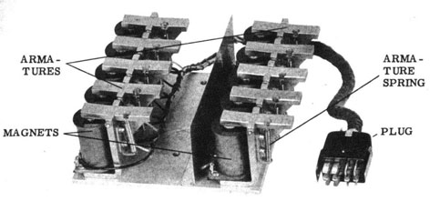
PLATE 1OA - STEPPING MAGNET ASSEMBLY
|
|
PLATE 10B - TAPE MOISTENER and CUTTER
|
|
PLATE 10
|
| |
-63-
|
|
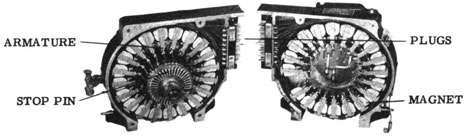
PLATE 12A - CCM MARK 1 - CSP 1600
|
|
PLATE 12B - CONTACT ARMS and CONTACTS
|
|
PLATE 12
|
| |
-66-
|
|