4-2. PROCEDURE. For the purpose of this section the Type H Mark 8 Catapult is assumed to be in "secured" condition initially, with accumulator air charges blown off, see paragraph 4-29. To prepare the catapult for use, the following steps are taken:
WARNING
In order to prevent premature cutoff caused by cold fluid in the runaway shot preventer, catapult compartment temperature shall be maintained at a minimum of 72° F. during catapult operations. After periods of inactivity and prior to resumption of operations, the minimum temperature (72° F.) must be maintained for a minimum period of twelve hours.
a. Open launching and retracting accumulator liquid level gage shutoff valves and determine fluid levels.
b. Open launching and retracting gravity tank level gage shutoff valves and determine fluid levels. Add fluid if required.
c. Open gate valve in launching gravity tank return line from engine cylinder.
d. Open pump discharge shutoff valves. Open pump gravity tank return shutoff valves. Open pump suction line valves. Turn pump by hand through several revolutions.
e. Turn on electrical power to pumps and signal system.
f. Determine that the following valves are in the proper operating position:
1. Drain valves and vent valves on engine cylinder, ram, brake cylinder, elbow check valve, air flasks, manifolds, piston valve, hydraulic stops, constant pressure valve, bridle tensioner jacks, cable whip dampers, and cable tensioner - closed.
2. Air charging valve on launching accumulator - closed.
3. Air blowoff valve for launching accumulator - closed.
4. Fluid blowdown valve for launching. accumulator - closed.
5. Air shutoff valve for launching accumulator - open.
6. Shutoff valves on launching pressure regulator - open.
7. Air charging valve for retracting accumulator - closed.
8. Air blowoff valve for retracting accumulator - closed.
9. Fluid blowdown valve for retracting accumulator - closed.
10. Air shutoff valve on retracting accumulator -open.
11. Shutoff valves on retracting pressure regulator - open.
12. Air charging valve for cable whip dampers -closed.
13. Air blowoff valve for cable whip dampers -closed.
14. Air charging valve for cable tensioner - closed.
15. Air blowoff valve for cable tensioner - closed.
16. Air charging valve for constant pressure valve - closed.
17. Air blowoff valve for constant pressure valve - closed.
18. Condensate vent valve for constant pressure valve air supply - closed.
19. Supply valve to four-way valve - open.
20. Firing operating valve supply valve - closed.
g. Check constant pressure valve spindle for proper position and bypass valve for freedom of motion.
h. Open shutoff valve to low-pressure air supply and check pressure.
i. Open shutoff valve to high-pressure air supply and check pressure.
j. Open shutoff valves to drain pump and operate pump to charge constant pressure valve auxiliary dome, four-inch line, and air trap cylinder with fluid.
k. Drain constant pressure valve lower dome and add one pint of 2190 oil to the chamber to act as a lubricant for the packing. Blow off condensate from air supply line and charge dome with air to 260 psi.
l. If required, operate one pump only to charge accumulators to operating levels (9 inches in center gage of launching accumulator and 5 inches in gage of retracting accumulators).
WARNING
Insufficient pump lubrication may occur when pump is operated at low back pressures. In order to operate pump under this condition, throttle pump discharge pressure to 200 psi with pump on delivery to accumulator. No pump shall be operated longer than one minute under low back pressure conditions. Pump will discharge to accumulator when allowed to run idling without several hundred psi in accumulator.
m. Check cable tensioner dome for proper fluid level. Charge with air to 800 + 25 -10 psi.
n. Check cable whip damper domes for proper
52
fluid level. Charge with air to 800 + 25 - 10 psi.
o. Charge retracting accumulator with air to 300 psi. Vent hydraulic stops. Open blowdown valve briefly.
p. Depress retracting pushbutton to fill brake cylinder. Vent thoroughly and close vents tightly. Operate one pump as required to maintain fluid level. Vent elbow check valve at gland around rod.
q. Charge launching accumulator with air to 750 psi.
r. Open valves in lines to bridle tensioner pump.
s. Check shuttle track for obstructions, freedom of motion of shuttle, and wear of shuttle slippers. Operate shuttle positioner to check for proper functioning. When moving shuttle aft, crosshead motion from battery position is avoided by depressing the retracting button. Position shuttle with aft end of shuttle 20 inches from end of track.
t. Lubricate catapult, review all maintenance schedules.
u. Charge retracting accumulator with air to 850 psi at 5 inch fluid level in gage.
v. Mount engine indicators on engine cylinder and brake and open shutoff valves.
w. Test launching and retracting pump operation using one pump at a time in the following manner:
1. Set selector switch of pump regulator on standby position (signal lights out). Set regulator at minimum pressure setting.
2. Start first pump motor. Check for proper idling pressure, proper operation, and delivery.
3. Repeat for each launching and retracting pump. Set levels at 9 inches and 5 inches as before.
x. Check runaway shot preventer for the following:
1. Oil level in reservoir at red line on level gage with crosshead in battery position.
2. RSP valve spring at correct setting.
3. RSP switch clears indicator rod by 0.010 inch.
4. Check attachment of extension rod to piston rod.
5. Reservoir charged with air to 15 psi. Cylinder and valve vented.
y. Vent the catapult at the following places:
1. Main engine cylinder (vent at each end).
2. Ram and brake cylinder while depressing "RETRACT" button. Vent at the top of the ram collar and the top of the brake spacer, collecting one gallon and three gallons respectively from the vents in a clean container to enable returning the fluid uncontaminated to the retracting system.
3. Hydraulic stops.
4. Elbow check valve.
5. Bridle tensioner jacks.
6. Piston valve.
7. Cable tensioner.
8. Air trap cylinder and line (as in paragraph 4-2j).
z. Check signal system for proper functioning See paragraph 5-8k.
aa. Prepare catapult for no-load launchings. See paragraph 4-10. Complete and sign checkoff list.
bb. Make several no-load launchings at 750 psi. Then secure catapult.
cc. Check bridle tensioning force at shuttle with dynamometer. See paragraph 5-8(1).
dd. Take on air charge in launching accumulator as ordered by catapult officer in preparation for operations.
4-3. CATAPULT OPERATION.
4-4. GENERAL. Launching accumulator pressures to be used are specified in Bureau of Aeronautics catapult bulletins for each model of airplane. The bulletin instructions shall be adhered to. The catapult officer shall be responsible for verification of the correct launching accumulator pressure for each launching. He is also responsible for the transmission of this information to the catapult operator, stationed at the firing control panel of the catapult engine. The catapult officer is responsible that the proper holdback unit assembly, release assembly, pendant arrester, and shuttle tensioning force are used.
4-5. SEQUENCE OF OPERATIONS.
4-6. GENERAL. The number of crewmen, and their assigned duties, while manning the catapult, is at the discretion of the Commanding Officer.
Note
Signals between catapult officer, pilot, crewmen, and control operator must be clearly understood before any launching is made.
Planes to be catapulted should be ready for flight, catapult crew at stations, and planes' engines idling.
4-7. LAUNCHING OPERATING PROCEDURE. The following steps comprise the normal launching operating procedure:
a. The two men assigned to launching bridle engage it with the shuttle towing fitting and hold it in readiness by means of quick detachable lines of sufficient length to keep them clear of propeller or jet suction.
b. The plane is taxied into position. Handling crew check that the plane is centered and that tail or nose wheel is locked. The off center catapult spotting distance of the airplane nose gear and/or main gear shall not exceed three inches either side of center.
c. The men assigned to launching bridle approach plane from either side, observing safety precautions especially those concerning jet suction and blast
53
areas. They attach the bridle to the plane's towing hooks and hold it in place until tensioned, seeing that the bridle is correctly hooked to both the plane and shuttle fittings.
d. At the same time, the man assigned to the holdback and release unit, after observing safety precautions while approaching the plane, engages the holdback and release unit with the plane's holdback fitting. He waits to check that the holdback and release unit remains engaged during tensioning.
e. While plane is being spotted, the catapult operator at the firing control panel obtains correct launching accumulator pressure, if not already at correct pressure, and keeps pressure control set to the figure ordered. The operator at the retracting control panel keeps pressure control set to proper retracting accumulator pressure.
f. The firing control panel and the retracting control panel operators both press their "FIRST READY" buttons lighting a white light at all signal stations.
g. When deck edge control operator and catapult officer see the white light, and the handling crew is ready, the catapult officer signals for "BRIDLE TENSION".
h. The deck edge control operator depresses "BRIDLE TENSION" button, tensioning the bridle and lighting the green "STANDBY" light at each of the four signal stations.
WARNING
The shuttle positioner pushbuttons shall never be used for bridle tensioning.
i. The two bridle crewmen make a final check of bridle for proper tension and position and stand clear, observing safety precautions.
Note
If bridle is not properly engaged, during launching power stroke the bridle will be jerked from its correct position imparting sufficient forward motion to plane to break its connection to the catapult. Since plane is under takeoff power it will taxi rapidly forward and unless the pilot immediately applies the brakes, the plane may fall over the side. The only indication of malfunction to the pilot will be the lack of abrupt catapult takeoff acceleration and he must instantly apply his brakes.
j. The holdback and release unit crewman makes final check of holdback and release unit, signals the catapult officer and moves clear, observing proper safety precautions.
k. The catapult control panel operators upon seeing white and green lights, recheck accumulator, tensioner, constant pressure valve, cable whip damper, and low-pressure air supply gages for proper pressure, recheck liquid level gages for proper fluid level, and when in readiness, the firing control panel operator depresses "FINAL READY" button, lighting a red light at all four stations.
Note
Liquid level gages on launching and retracting accumulators will be read and logged prior to each launching. Lag in level gages may prevent accurate check of fluid level between each launching during rapid operations.
1. The catapult officer when ready, and when noting white, green, and red lights, gives the signal "FIRE" to the deck edge control operator. The deck edge control operator depresses the "FIRE" button firing the catapult and adding a red "FIRE" signal to the three control panels. The signal lights at all stations are then blanked out during the launching cycle of the catapult clearing the panels for the retracting signals.
Note
Retensioning operation at any time, prior to firing the catapult, may be accomplished, by the deck edge control operator, by depressing "RETRACT" button until amber "X-HEAD BATTERY" signal light lights. This will blank out the white "FIRST READY", green "STANDBY", and red "FINAL READY" lights, and return the catapult to battery position. The sequence of operation is resumed by the panel operators obtaining the white "FIRST READY" lights.
4-8. RETRACTING OPERATING PROCEDURE. The following steps constitute the normal retracting operating procedure:
a. When the catapult officer sees that the launching track is clear and that the shuttle has come to complete stop, he signals the deck edge control operator to "RETRACT".
WARNING
The "RETRACT" button shall not be depressed until the shuttle has come to a complete stop after rebound.
b. The deck edge control operator depresses the
54
"RETRACT" button until the amber "X-HEAD BATTERY" signal lights indicating the crosshead is fully retracted to battery position. The amber "X-HEAD BATTERY" signal lights at the firing control panel at the same time. The deck edge controls operator then releases the "RETRACT" button. Retraction is to be continuous throughout the stroke, except when an emergency arises.
c. Following the completion of retraction, the panel operators continue preparation for the next launching, obtaining required accumulator pressures and checking all other pressures. When their preparation is completed, they signal "FIRST READY".
4-9. SIGNALS RECOMMENDED. The following are the recommended signals for aircraft launchings:
a. Signals between catapult officer and catapult crew are left to the discretion of the Commanding Officer.
b. Signals between catapult officer and pilot, when catapult is at "FINAL READY" and plane is fully tensioned, are recommended as follows:
1. TURN UP ENGINE TO CHECK OPERATION. Catapult officer swings arm overhead in circular motion with one finger raised.
2. AFFIRMATIVE ENGINE OPERATION CHECK. Pilot nods head affirmative.
3. NEGATIVE ENGINE OPERATION CHECK. Pilot shakes head negative indicating check must continue and signal in 1. above must be repeated by catapult officer before TURN UP, READY TO GO signal is made.
4. TURN UP, READY TO GO. Catapult officer swings arm overhead in circular motion with two fingers raised.
5. TURNING UP. Pilot extends arm, palm down, from the side of plane within view of catapult officer.
6. READY TO FIRE. Pilot draws arm into plane and sets himself for launching.
7. SECURE. Pilot instead of drawing arm in for READY TO FIRE waves his extended arm horizontally until signaled by catapult officer to secure. He then idles or stops the plane's engine.
8. NO SIGNAL WILL BE MADE BY PILOT AFTER HE HAS GIVEN READY TO FIRE SIGNAL.
c. Upon seeing pilot's arm withdrawn and after checking visually and by signal with the control operator, the catapult officer gives the signal to deck control operator to "FIRE".
Note
After pilot gives READY TO FIRE signal, the catapult officer is in charge and responsible for the operation. He shall invariably exercise his discretion and hold up the launching if it appears advisable to do so
for any reason.
4-10. "NO LOAD" LAUNCHINGS.
4-11. GENERAL. These launchings are made prior to the first series of aircraft launchings, after modification to the installation, or after any period of idleness to check satisfactory performance and operation of the catapult.
4-12. Preparation for "NO LOAD" launching is identical to preparation for launching as given in paragraph 4-2 with the following exceptions:
a. After signal system check has been made, the bridle tensioner pump shall be turned off to prevent movement of crosshead when "BRIDLE TENSION" button for standby is depressed.
b. Launching accumulator pressure shall be brought to 750 psi.
4-13. The launching is conducted in the same manner as regular aircraft launching set forth in paragraphs 4-5 to 4-10 less the instructions pertaining to the plane. On completion of a "NO LOAD" launching the catapult is secured and the launching accumulator pressure is brought up CO charge required for anticipated operations.
4-14. "NO LOAD" LAUNCHING SIGNALS. "NO LOAD" launching signals are left to the discretion of the catapult officer.
4-15. SUPPLEMENTARY OPERATING NOTES.
4-16. The magnitude of the peak accelerations which occur at the start of a hydraulic catapult launching are adversely affected by the presence of entrapped air in the hydraulic fluid. In addition, excessive pressures are introduced at the piston valve upon firing. With respect to the Type H, Mark 8 catapult, entrapped air, freed at the end of the power run, may prevent opening of the elbow check valve and delay retraction until it has been removed by venting. These conditions are particularly critical when operating at high pressure and rapid launching cycles. To minimize the effects of the entrapped air in the hydraulic systems it is recommended that in selecting a basic launching charge a charge be chosen so that the launchings will be made at the highest accumulator liquid level practical thereby further isolating the compressed air mass from the engine cylinder. Sequence of flight operations and selections of basic charges shall be coordinated so that it will not be necessary to decrease launching pressure during operations by blowing down considerable quantities of fluid. If necessary to blow down fluid, vent the launching system thoroughly before resuming.
55
4-17. The minimum launching accumulator level for the H8 catapult is 9 inches in the center gage. A strict compliance to this minimum launching accumulator fluid level as the lowest level ever to be used is mandatory to prevent introduction of free air into the engine cylinder from the accumulator. A level drop may occur because of air charge heating during operations and must be corrected by blowing off air till fluid level rises above minimum level before "FINAL READY" signal is given. This difficulty may be avoided by using a higher initial level as recommended above.
WARNING
No launching shall be made with fluid level below the minimum specified for the catapult.
4-18. Set pump pressure regulators accurately to required accumulator pressure by starting at a lower pressure and increasing setting by increments until pumps unload at desired accumulator pressure. Check pressure setting by blowing down fluid until pumps go on stroke and note if desired pressure is maintained. When lower accumulator pressure is desired, decrease setting by an amount slightly greater than that required, blow down fluid until accumulator pressure is slightly less than required and proceed as before.
4-19. Every precaution must be taken to prevent launching a plane at unsuitable pressures. Accumulator pressures other than those prescribed for type and weight of plane will result in insufficient speed or excessive acceleration incident to excessive speed. These conditions are dangerous for pilot, airplane, and catapult.
4-20. Every precaution must be taken to prevent entry of foreign matter into the fluid system of the catapult. If temporary openings into system become necessary, suitable coverings or plugs shall be used to prevent contamination.
4-21. Maintain the specified air charge making up for leakage and absorption by charging additional air as required. During operations, with long intervals between launchings, the decrease in air volume, by absorption losses, may be greater than the increase in air volume, due to heating, and the fluid level may rise slightly.
4-22. Unless fluid is visible above 3 inches in the lower launching accumulator level gage, or 5 inch level in the retracting accumulator level gage, do not allow the catapult to stand under pressure nor attempt to charge air into accumulators. Unless this precaution is observed air may leak back through the check valve into pumps and gravity tanks.
4-23. Do not fire the catapult unless certain that the bridle is correctly installed and under sufficient tension when full airplane thrust is acting, to prevent overload of bridle at start of launching.
4-24. When emptying the accumulators of fluid, as the fluid level in the gravity tanks rises, close blowdown valves gradually to reduce flow. If this is not done fluid may be lost through the vents when the air finally blows through the valve.
4-25. It shall be the responsibility of the catapult officer to order a check of the tensioning force at any time during normal launching operations when tensioning action of the shuttle indicates insufficient tensioning force. See paragraph 5-8(1).
4-26. End speed of shuttle, as shown on speedometer, and all other operating data shall be logged as ordered by catapult officer.
4-27. Special precautions regarding the brake cylinder are to be observed by all operating units. The braking action of the H8 catapult is obtained by quickly developing a high level of pressure in the brake cylinder and maintaining it until the system is stopped. Since air is an elastic medium, its presence results in a delay or failure in obtaining braking pressure. In order to reduce to a minimum the possibility that air may cause loss of part of the brake stroke, special instructions and precautions concerning the brake are required. The following special precautions regarding excessive air in the brake cylinder shall be observed:
a. Immediately before each series of launchings a special venting of the brake cylinder shall be performed as outlined in paragraph 4-2y(2).
b. Examination of the constant pressure valve sea: and of the spindle position shall be routine maintenance items, see paragraphs 5-8h and 5-12b.
c. Establish by experience what is a normal amount of air in the brake. The observation of any indication of excessive air shall be cause for securing the catapult for removal of the air and investigation of the source of the air.
d. Correct operating procedures must be follower at all times. Particular note shall be made of any abnormalities in operation such as excessive brake penetration, excessive rebound, fast retraction erratic motion of crosshead during retraction, excessive drop of retracting pressure, unusual sound, particularly those produced by air bubbling through the system, or any indication of air in the brake cylinder as shown by the indicator card.
4-28. SECURING THE CATAPULT
4-29. PROCEDURE. After any series of launching
56
operations have been completed, the catapult shall be secured in the following manner:
a. Manually place the piston valve securing stem into the "fully-in" position.
b. Close the main fluid supply valve to the firing operating valve and padlock the firing operating valve.
c. Perform daily maintenance schedule required and corrective maintenance as needed.
d. Check the retracting accumulator fluid for 5 inch level in the level gage. Adjust as required. Operate retracting pumps one at a time for one-half minute to clear air from pumps. Turn off each pump and close shutoff valve on discharge line of each pump. Before closing the shutoff valves on the pump discharge lines, operate each pump for approximately one-half minute to cause the "air free" fluid supplied by the pumps to force any "air charged" fluid (accumulator fluid under air pressure) trapped in the check valves, back into the manifold.
e. Check the launching accumulator fluid level for approximately 9 inches in the center gage. Blow down or charge, if necessary. The fluid level should not be increased to obtain the desired launching pressure until immediately before operations. This minimizes the amount of fluid which is in contact with the compressed air mass for long intervals of time.
f. Operate launching pumps one at a time for approximately one-half minute each to clear air from pumps. Turn off each pump and close shutoff valve on discharge line of each pump.
g. Set pressure regulators to minimum pressure and selector switches to "STANDBY".
h. Shut off all pumps including the bridle tensioner pump.
i. Close all accumulator level gage valves.
j. Vent the catapult. See paragraph 4-2y.
k. Check to see that all vents and plugs are closed.
l. Close gate valve to launching gravity tank.
m. Close all air supply Line valves.
n. Relieve air pressure in cable tensioner, cable whip dampers, runaway shot preventer reservoirs, and the constant pressure valve.
o. Check that fluid blowdown and air blowoff valves are closed.
p. Close supply valve to four-way valve.
q. Remove pressure indicator cards and install new ones.
r. Check that all launchings have been logged and that all maintenance and repair data have been logged.
s. Turn off electric power to motors and signals.
t. Padlock deck edge controls and pushbutton stations.
u. Remove and stow launching bridles and holdback release units.
v. Install tow fitting cover.
w. If the catapult is to be idle a long time, the following must be accomplished:
1. Blow off air from both accumulators.
2. Remove and store pressure indicators. Indicator valves remain on the catapult and shall be closed tightly.
57
SECTION V MAINTENANCE
5-1. GENERAL.
5-2. This section contains the requirements and the procedures of maintenance for the Type H Mark 8 Catapult. Maintenance will be presented in two aspects: Preventive Maintenance, which will detail the periodic lubrication and inspection procedures, and Corrective Maintenance, which will detail the correct procedures for replacement of worn or defective parts of the catapult.
5-3. PREVENTIVE MAINTENANCE.
5-4. Lubrication and periodic inspection schedules as given in this section shall be considered as only the minimum requirements of preventive maintenance. An effective preventive maintenance program demands of maintenance personnel a thorough knowledge both of the operation of the catapult in general and of the characteristic operation of each unit of the system in particular. This intimate knowledge of the normal operation of the catapult will enable the well-trained observer to detect any abnormal operation and to correct the potential causes of trouble. Maintenance must go far beyond a mere "wipe-down" and periodic lubrication. While a well-trained visual inspection may reveal signs of wear, corrosion, leakage, incorrect alignment, or other defects it should be accompanied by a mechanical inspection and an operational inspection. Mechanical inspection, performed while the catapult is idle, shall consist of a complete check for any looseness, excessive play, improper operation, or any abnormal resistance to motion. Fastenings shall be checked with suitable tools to detect looseness and, where possible, moving parts should be tested by manual movement to detect any excessive play or wear on bearing surfaces. Operational inspection must be considered a duty of all catapult personnel. Catapult personnel shall be instructed to bring to the attention of the catapult officer any and all observed abnormalities in operation. They shall be particularly instructed to watch for and note the following: sluggish retraction; fast retraction; erratic movement of the crosshead during the retracting stroke; excessive drop in retracting accumulator pressure; unusual sounds, particularly those caused by air bubbling through the system or into the brake cylinder; unusual drops of fluid level; excessive rebound from the brake stroke; excessive brake penetration; or any indication
of air in the brake cylinder as shown by the brake indicator card. See Section VI - Malfunctions.
5-5. A maintenance log should be kept for each catapult in addition to or as part of the catapult operating log required. All maintenance performed shall be logged. Critical measurements and changes in variable measurements should be logged so that they may be used to predict trends. Any differences in maintenance procedures for a particular catapult should be entered in the log and also, if necessary, posted at the engine.
5-6. The maintenance schedules given in this section are based upon daily use of the catapult. If the catapult is not in continuous daily use, the daily schedules may be carried out weekly and the weekly schedules performed monthly. If the catapult is inoperative for an extended period, the schedules as given for "Catapults Not in Regular Use" shall apply. Maintenance of catapults on vessels which are in an "inactive" status shall be in accordance with the preservation manual NAVAER 00-85A-500.
5-7. PREVENTIVE MAINTENANCE SCHEDULES.
5-8. DAILY SCHEDULE. The following schedule shall be accomplished daily:
a. Wipe down all machined surfaces of catapult to remove all grease, rust, fluid, oil, and dirt. During the "wipe-down" period all packings, couplings. and fittings should be inspected for leaks, and a thorough check for loose and/or damaged fastenings should be made.
b. Complete daily lubrication as required. See figure 5-1.
c. Inspect the complete catapult both visually and mechanically. Look for signs of wear, corrosion cracks, or breaks and make sure that none of the parts are loose or missing.
d. Inspect shuttle slippers for wear and replace if the slot is worn to 3/4-inch in width or greater.
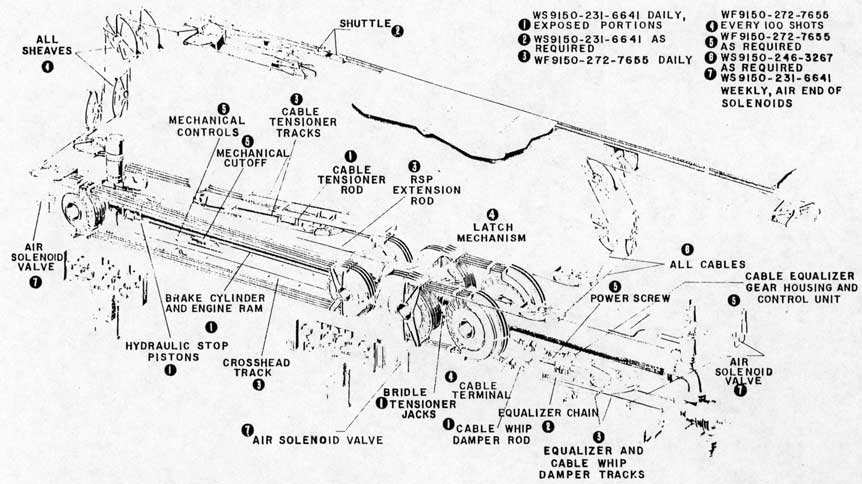
e. Inspect all cable terminals visually for damage or cable slippage. It is unnecessary to disassemble the terminal except in doubtful cases.
f. Pull out crosshead to allow access to all parts of cable and inspect towing and retrieving cables completely for broken wires or excessive wear. See
58
paragraph 5-60 for procedure.
g. Renew towing or retrieving cable if more than four wires in any one strand or a total of sixteen wires are broken in a cable within 5 feet of a fitting. If more than two wires in one strand or a total of eight wires are broken in any other 25-foot section of the cable, renew the cable. See paragraph 5-49 for procedure of installing cables.
h. Observe the position and condition of the constant pressure valve spindle. If the spindle has assumed a lower than normal position, the valve shall be disassembled for examination of the spindle and seat before further launchings are made. If cap of spindle is damaged it must be replaced before any launchings are made.
i. Vent engine after each series of launchings.
j. Check alignment of plug slots in bypass valve. See paragraph 5-62 for procedure.
k. Complete the daily check of signal system before making launchings. The catapult must be secured against launching with piston valve securing stem in, shutoff valve to firing operating valve closed, and firing operating valve locked. The low-pressure air and retracting pressure shall be on and the bridle tensioning pump shall be off. Operate through the normal deck edge control station. The following steps constitute the procedure for the daily check of the signal system.
1. Depress "FIRST READY" pushbutton (AF) on firing panel, then depress "FIRST READY" pushbutton (AR) on retracting panel. White lights labeled "FIRST READY" on retracting control panel, firing control panel, deck edge control panel, and auxiliary deck edge signal box shall light and the red light labeled "FB" on fly control bridge shall light.
2. Depress "STANDBY" pushbutton (BD) on deck edge control panel. Green lights labeled "STANDBY" on retracting, firing, and deck edge control panels and on auxiliary deck edge signal box shall light, and the bridle tensioner solenoid valve (BS) shall be energized.
3. Depress "FINAL READY" pushbutton (CF) on firing panel. Red lights labeled "FINAL READY" on retracting, firing, and deck edge control panels and on auxiliary deck edge signal box shall light and the latch solenoid pin locking the operating valve shall lift.
4. Depress "FIRE" pushbutton (DD) on deck edge control panel. Red lights labeled "FIRE" shall light on retracting, firing, and deck edge control panels and the four-way valve solenoid (ECS) shall be energized. The elbow check valve shall close, actuating the auxiliary firing switch (DDAux) and the firing solenoid valve (FS) shall be energized.
5. Depress the "RETRACT" button (HD). Nothing shall happen.
6. Turn bridle tensioning pump on. The crosshead shall be moved by the bridle tensioning jacks to
trip the "X" switch. Green "STANDBY" and red "FINAL READY" lights shall blank. Bridle tension solenoid valve (BS), four-way valve solenoid valve (ECS), and latch solenoid (LS) shall de-energize. Elbow check valve shall open releasing the DDAux switch and the firing solenoid valve (FS) shall de-energize. The red "FIRE" and white "FIRST READY" lights shall remain lit.
7. Depress the "RETRACT" button. Nothing shall happen.
8. Turn low-pressure air off and vent line. Manually rotate bypass valve towards closed position. When the "RV1" switch is tripped the "FIRE" lights shall blank and when the "RV2" switch is tripped the "FIRST READY" lights shall blank.
9. Turn low-pressure air on. Depress the "RETRACT" button and hold. The crosshead shall be retracted to battery position. Release the "RETRACT" button when the amber "CROSSHEAD IN BATTERY POSITION" lights are lit.
10. Replace any defective lamps and/or defective switches.
CAUTION
Under no circumstances shall the catapult be used for launchings if the signal system is found to be defective as a result of the daily check.
l. Complete the daily check of tensioning force. The following steps constitute the procedure for the daily check of the tensioning force.
1. Continual rapid launching of aircraft will produce a significant rise in catapult fluid temperature resulting in excessive friction due to expansion of catapult parts and may cause a serious reduction of tensioning force at the shuttle.
2. Indications of excessively low tensioning force can be recognized by a slow and/or sluggish action of the shuttle during tensioning, by a slack bridle or pendant after tensioning, and by sluggish action of the shuttle in picking up bridle slack during turnup of the airplane.
3. To prevent malfunctions resulting from reduction of tensioning force, the following maintenance practice shall be adhered to. Prior to each series of launchings and after every series which causes a significant rise in catapult fluid temperature, install a dynamometer at the shuttle and check for a tensioning force of 2000 plus 0 minus 100 pounds. In addition, it shall be the responsibility of the catapult officer to order a check of tensioning force at any time during normal launching operations when tensioning action of the shuttle indicates insufficient tensioning force.
4. If the dynamometer check indicates a tensioning force at the shuttle lower than 2000 plus 0 minus
59
100 pounds, the discharge pressure of the bridle tensioning pump shall be increased to give the desired force of 2000 plus 0 minus 100 pounds.
CAUTION
At no time shall a catapult be fired with a slack launching bridle or pendant.
5. "Established gage pressure" of the bridle tensioning pump is that discharge pressure which is normally sufficient to place a tensioning force of 2000 plus 0 minus 100 pounds on the shuttle. This pressure will vary for each catapult and shall be determined by dynamometer tests as above and posted on the catapult as the "established gage pressure" for that particular catapult.
m. Complete daily check of runaway shot preventer verifying the following items:
1. Oil level at red line on liquid level gage.
2. Air charge at 15 psi.
3. RSP extension rod properly attached and lubricated.
4. RSP valve indicator rod clearing RSP switch plunger by 0.010 inch.
5-9. WEEKLY SCHEDULE. The following schedule shall be accomplished weekly.
a. Clean entire catapult to remove all grease, rust, fluid, oil, and dirt. During cleaning make a visual inspection of the complete catapult.
b. Complete weekly lubrication as required in figure 5-1. Particular attention shall be directed to the lubrication of those parts of the catapult which may be exposed to the effects of weather such as the shuttle assembly and the exposed portions of the cables.
c. Disassemble, clean, and lubricate the internal parts of the air valve on all solenoid valves. See paragraph 5-59. Failure to clean these valves will result in malfunctioning.
d. All catapult bolts shall be checked for looseness or distortion and tightened or replaced as necessary. All high-pressure joints are prone to leak if unequal bolt tension exists, consequently, all bolts should be tightened equally if sealing ability is to be maintained. Replacement bolts must be equal to or greater in strength than the replaced bolt. Tools of the proper size should be used at all times. Special attention shall be given to the bolts for the following components:
No attempt shall be made to adjust the tension of bolts of any high-pressure joint while the joint is pressurized.
e. Check V-ring packing retainer ring on cable tensioner. This retainer ring has a tendency to turn and must be checked to insure that it is properly adjusted. Tighten only with fingers. Do not use a tool.
f. Check all hydraulic joints (gasketed and packer joints) for leakage. If leakage cannot be corrected by tightening of retainer or other means, the packings or gaskets must be replaced. (See the applicable sections of Corrective Maintenance for procedure for replacing packings or gaskets).
g. Drain condensate from constant pressure lower dome.
h. Check alignment between top of elbow check valve actuating rod and button of auxiliary firing switch (DD Aux). Alignment must be correct.
i. Relays shall be inspected and if any of the conditions noted herein are observed, they shall be remedied as noted. Check for dirt or grease and remove and keep clean. Check for worn or burned contacts and replace contacts if so damaged. Do not file, lubricate or dress up the contacts. Check for worn connections and replace and remove cause of wear. Check for loose connections and tighten if any found. Check for loose or broken parts in the relays.
j. Check weep holes at end of air trap cylinder piston rod for excessive leakage of fluid. See paragraph 5-83 for procedure to correct leakage.
k. Check liquid level gages. Blow down or drain if condensation has caused colorless fluid to settle in the top of the gage glass. See paragraph 5-68.
l. Check RSP latch bumper pad.
m. Inspect all pump suction line strainers an clean as required.
5-10. SEMIMONTHLY SCHEDULE. All air flask: shall be drained of fluid and condensate, semimonthly to prevent reduction of catapult end speed. The drain age is done as follows:
a. To drain, "crack" the 3/4-inch globe valve a bottom of each air flask. The drain valve shall be closed immediately after the flow of liquid stops r prevent any excessive loss of air charge.
Note
This drainage may be accomplished with catapult charged.
60
5-11. MONTHLY SCHEDULE. The following are the procedures of the monthly schedule:
a. Check tools, supply of tension rings, tension bars and bridles, and spares on hand and expended items against allowance list and requisition anticipated needs.
b. Calibrate pressure indicators with a dead weight pressure gage tester.
c. An inspection of all catapult sheaves shall be made to determine excessive groove wear. Investigation of wear on cast aluminum sheave cable grooves indicates that sheaves should be replaced when the depth of the groove, measured from the O.D. of the rim to the bottom of any cable marks in the throat of the groove, has increased 1/4-inch. The following table depicts the maximum cable groove wear depths allowable:
NAFACT PART NO.
TYPE SHEAVE
SIZE
GROOVE DEPTH
88946-1
Engine
38
1-3/8
62-4511-1
Drive
38
1-3/8
62-4510-1
Drive
48
1-5/8
62-4335-1
Engine
48
1-5/8
When the maximum allowable groove depths specified in the above table have been reached, sheaves shall be replaced. Normally, these limits should not be exceeded, however, in emergencies where operational conditions will not permit, immediate installation of new sheaves may be deferred for a short period.
5-12. COMPLETION OF 1500 LAUNCHINGS. The following schedule shall be carried out on completion of 1500 launchings.
a. Inspect shuttle hooks for a pattern of wear on top surface of hook link caused by interference between shuttle hooks and track cover plates. See Section VI - Malfunctions. If pattern of wear exists, remove hook and replace with spare. See paragraph 5-168 for procedure.
b. Remove the constant pressure valve spindle and seat and make a minute examination of the spindle and seat for any evidence of cracks, chipping, deformation, scoring, enlargement, or "out-of-roundness". Either part shall be replaced if defects are found.
5-13. QUARTERLY SCHEDULE. The following maintenance procedures shall be performed quarterly:
a. Calibrate all pressure gages.
b. Inspect piston of firing operating valve. See Paragraph 5-98 for removal procedure.
c. Inspect piston of damping cylinder. See
Paragraph 5-143 for removal procedure.
d. Check flexible couplings on pumps. Replenish lubricant if necessary.
e. Check capacity of power plant pumps. See paragraph 5-54 for procedure.
f. Inspect Vickers pump pilot valves for freedom of corrosion or gumming, and clean as required.
g. Disassemble, clean, and inspect constant pressure valve dome. Introduce about one pint of Symbol 2190 oil into lower dome during reassembly.
5-14. SEMIANNUAL SCHEDULE. The following maintenance procedures shall be performed semiannually:
a. Check relief valve settings on all pumps. See pump manuals for procedures.
b. Disassemble and inspect all cable couplings and terminals. See paragraph 5-38 for procedure.
c. Test glycerine-water-borax fluid in cable- whip dampers for alkalinity. See paragraph 5-162 for procedure.
d. Test glycerine-water-borax fluid in cable tensioner for alkalinity. See paragraph 5-151 for procedure.
e. Remove accumulator safety valves and perform a valve lifting pressure test (depending on availability of suitable test facilities).
f. On completion of 1000 launchings, or at the end of six months, take fluid samples from gravity tanks.
g. Check alignment of cable tensioner cylinder and tracks.
5-15. CATAPULT NOT IN REGULAR USE. When the catapult is not in regular use, the special precautions listed in this paragraph shall be taken to prevent corrosion and insure preservation. These precautions do not constitute the methods of preservation for catapults on vessels which are in an inactive status. See paragraph 5-6.
a. Paint all exposed nonmachined surfaces.
b. Coat all exposed machined surfaces with rust preventive compound.
c. Run cable tensioner, cable whip damper, and bridle tensioner pistons "fully in" their respective cylinders. Fill these units to capacity with their operating fluids.
d. Retract ram fully. Secure pump discharge shutoff valves, high- and low-pressure air shutoff valves, and all shutoff valves on liquid level gages.
e. Lubricate complete catapult.
f. Weekly, all rotating parts (sheaves, pumps, and motors) shall be turned through at least one complete revolution, and all sliding parts (shuttle, engine, cable whip damper, cable tensioner crosshead, cables, bridle tensioner piston, etc.) shall be moved sufficiently to check that seizing has not occurred. If
61
any excessive friction is noted, the cause shall be immediately located and eliminated.
g. If, during the inoperative period, any openings are created, they shall be covered to prevent entrance of any foreign material into the system.
h. If practicable, the accumulators and air flasks should be completely filled with their operating fluid for the prevention of corrosion. Particular attention is directed to the necessity for having the catapult engine filled with fluid at all times to prevent corrosion of internal finished surfaces. Periodic additions of operating fluid may be required to prevent formation of air pockets within the engine caused by air separating from the initial charge of fluid.
5-16. LUBRICATION SCHEDULES. The recommended minimum lubrication schedule for the catapult is shown in figure 5-1. The illustration specifies the recommended lubricant and the minimum frequency of application. A brief description of each of the recommended lubricants is given in the following table:
GENERAL STORES NO.
DESCRIPTION
WS9150-231-6641
Symbol 2190. A general purpose oil for all applications which do not require special lubricants.
WF9150-272-7655
An all purpose grease, combining water resistance, rust inhibition and good low-temperature characteristics.
WS9150-246-3267
A protective type grease also known as "cable lubricant" and "gear shield". Heated before application.
In addition, the manufacturer's manuals supplied with the special machinery of the catapult, such as pumps, motors, and pressure indicators, will give the lubricants required for their maintenance.
5-17. CORRECTIVE MAINTENANCE.
5-18. Corrective maintenance procedures as presented shall be considered the optimum procedures and any deviations from the recommended procedures must be carefully considered and approved by the catapult officer before their use is permitted.
5-19. Corrective Maintenance will be presented in two parts - General Procedures and Detailed Procedures. General Procedures will include those corrective maintenance procedures which are applicable
to more than one unit of the catapult or are applied to the catapult as a whole. Detailed Procedures will treat of those maintenance procedures peculiar to one unit of the catapult and will be detailed in their application to their particular unit but will not repeat procedures treated as General Procedures.
5-20. GENERAL CORRECTIVE MAINTENANCE PROCEDURES.
5-21. PACKINGS.
5-22. O-RING PACKINGS - RUNNING AND STATIC SEALS. The following are the proper techniques for installation and maintenance of O-ring packings:
a. All surfaces shall be absolutely clean, free from dirt, grit, and foreign material. When installing O-rings saturate them with oil conforming to Specification MIL-O-5606. Excessive use of grease, Specification AN-P-51 (petrolatum), must be avoided. O-rings can be stretched without difficulty and will recoil immediately but extreme care shall be exercised that no scraping or cutting is incurred when they are passed over or through threads and sharp edges.
b. Where an O-ring packing is used as a running seal and leakage occurs, replace it with a new O-ring.
c. If leakage appears at an O-ring gasket (static seal) check for metal to metal contact of the flanged surfaces by checking nuts or bolts for proper tightness. Excessive tightening must be avoided in all cases Rework or replace parts as necessary. If joint still leaks, install a new O-ring.
5-23. REPEATED FAILURE OF O-RINGS. If at O-ring fails frequently the cause must be eliminated For static seals, repeated failures could be due to loose joint, misaligned parts, or excessive clearance Joints which have a tendency to loosen must be tightened frequently. Where misalignment or excessive clearance occurs the parts must be repaired or replaced. In the case of running seals the difficult might be due to excessive clearance or rough surface.
5-24. V-RING PACKING - SYNTHETIC RUBBER The following are the proper techniques for installation and maintenance of V-rings:
a. Lubricate packing during installation at assembly of hydraulic components with oil conforming to Specification MIL-O-5606. If necessary, only light coating of petrolatum, Specification AN-P-5 shall be permitted. Excessive use of this grease must be avoided. Remove the D-ring from the packing ring which is next to the male adapter.
b. Packings must be assembled by installing the individual rings, one at a time, rather than seven
62
Figure 5-1. Lubrication Chart
63
rings together. Each ring shall be inserted individually making sure that it is properly seated before installing the next packing ring. To allow air trapped between individual rings to escape when they are inserted, provide a vent by carefully pushing a smooth, flat tool or stick between the sealing lip and the stuffing box wall. Extreme care shall be exercised not to scrape or mar the surfaces of the packing ring or the stuffing box wall, when venting.
c. Design requirements are that the packing have a small amount of "float", that is, the space into which the packing is to be installed be greater than the stack height of the packing rings and adapter by 1/32- plus or minus 1/64-inch. Greater space results in poor sealing action and leakage, while too little space results in binding and wear. Adjust packing gland as required to provide this dimension.
d. Where split packing is used as replacement, joints shall be staggered approximately 90° apart on successive packings. Adjustment is necessary in split V-ring installations to seal the joints. Flanges shall have a metal to metal contact, but excessive gland pressure shall be avoided. Do not trim split packings. A slight overlap at the joints is necessary for a proper seal and for satisfactory operation.
e. In double-acting cylinders, opposing sets of packings shall be installed with sealing lips facing towards the pressure. The female support ring shall be adjacent to a fixed or rigid part of the piston. The lips of the opposing sets of packing shall face away from each other.
f. Solid ring installation is mandatory where rotation is involved. At no time shall the metal male or female support ring rotate on the set of packings.
g. If leakage appears at V-ring packing joints, check the gland ring for metal to metal 'contact on the flanged surfaces. Rework or replace parts as necessary. If leakage continues, remove and examine packing for damage or wear.
h. When shims are necessary, a shim or shims of suitable thickness shall be placed under the flat side of the follower to take up the slack in the stuffing box.
5-25. COPPER GASKETS. When leakage occurs between two surfaces where a flat copper gasket is employed, reduce pressure on system and tighten all nuts equally to maintain the sealing ability. If leakage persists either anneal gasket and reinstall or replace with a new gasket as necessary.
5-26. WIPERS - FELT AND METALLIC. Felt wipers provide lubrication to extended rods subject to dust, dirt, and other foreign matter. The augmenting metallic wiper ring shall have free and unrestrained action. Check felt wipers and if worn, excessively dirty, or imbedded with metal particles, replace with new wipers. Dirty wipers may be washed with kerosene and reused.
5-27. CLEANING AND INSPECTION OF PACKED JOINTS. In all instances where joints have been broken to examine or replace packing, wipe the contact surfaces, the piston, and the cylinder interior with a clean cloth and closely inspect them for scratches, burrs and sharp edges. Hone down rough spots with a fine carborundum stone, before reinstalling the parts.
CAUTION
Never attempt to adjust a packing gland or a flange on a vessel that is pressurized.
5-28. WIRE ROPE.
5-29. CARE AND HANDLING OF WIRE ROPE CABLE. The following techniques and precautions shall be observed in the care and handling of wire rope cable. Wire rope used for cables is a preformed wire rope selected because of its sufficient strength and its ability to withstand repeated bending, wear, and distortion. Performance ability and length of service, however are directly dependent on the amount of care used in handling and proper inspection and lubrication in use.
5-30. Proper care begins with a correct unreeling of the cable, and the most valuable inspection of wire rope cable is the initial inspection while unreeling. When cable is unreeled, the reel must rotate. Generally a shaft is put through the center of the reel and jacked at both ends so the reel will rotate freely. A board should be held against one flange of the reel as a brake to prevent the reel from rotating too fast. Cable must be pulled straight from reel. Sufficient strain should be kept on the cable to prevent loosening of the cable remaining on the reel. Cable must never be taken off a reel by slipping over the flange without rotating the reel, as this will cause it to be twisted as each turn is taken off. Each twist of the wire rope cable is a potential kink, and a wire rope once kinked is damaged beyond repair at the point of kinking. Kinking of a cable forces strands and wires out of position and causes unequal tension and excessive wear at the point of kinking. Even though a kink is straightened, so that damage appears to be slight, the adjustment between strands has been disturbed and the cable cannot give its expect service. Close inspection should be made of the cable as it unreels and any cable which shows signs of cuts, burrs, or kinking should not be used.
5-31. SEIZING. When sufficient wire rope has been unreeled, it should be seized on each side of the intended cut before cutting to prevent unlaying of the strands. The nominal distance between seizings is five times the diameter of the rope. Seizing should be done in a workmanlike manner with not less than eight nor more than ten wraps of seizing wire for each
64
seizing made. One seizing on each side of the cut is sufficient for preformed wire ropes. Proceed with seizing as follows:
a. Wind the seizing wire on the wire rope by hand, keeping the coils together and keeping a considerable amount of tension on the wire.
b. Twist the ends of the wire together counterclockwise by hand so that the twisted portion is in the middle of the seizing.
c. Using cutters, grip the ends of the seizing wire just above the first twist. Twist with cutters just enough to take up the slack. Do not try to tighten seizing by twisting with cutters.
d. Tighten the seizing by prying the twist away from the axis of the rope with cutters.
e. Tighten the twist again as in step c. Repeat steps d. and e. as often as is necessary to make the seizing tight. Cut off the ends of the seizing wires and pound twist flat against the rope.
f. Cut wire rope between seizings with the cutting tool that is provided for that purpose, or with a fine tooth hacksaw.
5-32. To obtain maximum life of wire rope, it must be handled properly while reeving onto sheaves. The first step in installing new wire rope is a complete inspection of all sheaves on which the rope will run. If sheaves are found to be corrugated, they must be replaced. The new rope will not track in the corrugations made by the old rope. The rope will wear rapidly and friction will be increased, with the rope being forced to do more than its designed amount of work. Sheaves that do not run true, that wobble on their bearings, or are misaligned will also cause damaging friction or twisting of ropes. Misalignment or wobbling can be detected by uneven groove wear. Grooves or sheaves must be free from roughness of any kind. Replace any sheave that does not have a smooth, hard, true-running wearing surface. A sheave groove becomes deeper by wear rather than wide. Therefore, sheave groove diameters should be checked monthly (see paragraph 5-11c) and all sheaves not having proper grooves must be replaced to prevent pinching of rope and excessive friction and wear.
5-33. While reeving onto sheaves, it is imperative that wire rope not be allowed to twist or bend. Improper bending of a wire rope may reduce its life as much as 50 percent. When properly installed, further care of rope will include lubrication and frequent detailed inspection. Inspection is necessary not only to anticipate failure, but also to determine the cause of wear and failure.
5-34. A wire rope may be considered a complicated piece of machinery. As the rope bends over sheaves, the individual wires constantly move and rub against
each other. Each wire becomes a bearing surface that glides and wears against other wires. It is this wear, plus fatigue, that finally causes failure of wire rope.
5-35. INSPECTION OF WERE ROPE. Due to the method of manufacture, preformed wire rope cable as used in catapult cables requires closer inspection than nonpreformed rope. The essential difference is that preformed rope is given an additional process which forms the wires and strands into a spiral so that they lie naturally in place with a minimum of internal stress. This results in a more flexible, easier to handle, and longer-lasting rope. These advantages at the same time present a difficulty in inspection which must be remembered. A wire broken from wear in a non-preformed rope will spring out from the rope and is easily noticed on inspection. A wire broken in a preformed rope will tend to lie flat against the rope, making detection possible only with a close inspection.
5-36. Close inspection will not only show when to replace rope, but will also show the cause of defects. Wires breaking without wear indicate excessive twisting or bending. Wires wearing excessively without breaking indicate sheave grooves have worn small. Uneven wear at one point indicates a kink. Frequent inspection and tracing of defects will make maintenance personnel familiar with the causes of defects and prompt removal of causes will greatly lengthen the service life of rope.
5-37. LUBRICATION OF WIRE ROPE. Correct lubrication is equally important with inspection. Since the wire rope is a machine, all parts of which are constantly grinding and wearing on each other, the importance of complete and thorough lubrication is evident. Wire rope is internally lubricated during manufacture to an extent sufficient to last the service life of the rope. External lubrication, besides guarding against corrosion and reducing abrasion, also acts to seal in this internal lubrication and so prolongs the service life of the rope. It is desirable that rope be clean and dry before lubrication. Lubricant is best applied by hand with leather gloves. The rope should be completely lubricated each time. Regular inspection with frequent application of lubricant produces better results than heavy coatings less frequently applied. Use General Stores No. WS9150-246-3267 lubricant and heat before application. See paragraph 5-16.
5-38. SEMIANNUAL INSPECTION OF CABLE TERMINALS. The following are the steps of procedure for the semiannual inspection of cable terminals.
a. Disassemble the coupling and clean the poured terminal using a stiff bristle brush and a suitable solvent such as kerosene or Stoddard's solvent. Be
65
sure to clean thoroughly around the base of the terminal removing all grease or dirt accumulations at the base and as far inside the terminal as possible.
b. Inspect the top of the terminal for any evidence of individual wire slippage in the zinc or any depressions in the zinc filling. Inspect to see that the zinc has penetrated to the base of the terminal. See that the lay of the wire rope is not disturbed below the base of the terminal and that the terminal is properly aligned with the wire rope. Wire slippage, depression of the zinc more than 1/32-inch, incomplete zinc penetration, unlaying of the wire rope or misalignment of the terminal are all causes for rejection and the defective terminal shall be cropped and re-poured.
c. If the terminal shows none of the defects listed in the above paragraph, it should be immersed and soaked in Preservative Compound, General Stores No. G52-C-3257-30, -38, or -45, and reassembled. Make sure that the preservative compound runs into the base of the terminal and coats the wire rope wherever the lubricant has been removed by the solvent used in cleaning the terminal. Catapult poured terminals may be retained in service provided they satisfactorily pass each semiannual inspection.
d. It should be remembered that these inspections can only serve to detect faults which occur as a result of improper terminal pouring procedure. There is no alternative in the prevention of terminal failure but to follow precisely the instructions for pouring catapult terminals. It is recommended that the instructions for pouring catapult terminals given herein be studied by all operating personnel at the earliest practicable date, and used for reference during the pouring of all terminals.
5-39. POURING OF CABLE TERMINALS. During catapult operations, the terminals must be able to withstand high stresses. Consequently, the instructions given on the method of pouring the terminals must be carried out with extreme care and accuracy. All poured-type terminals are to be installed in exactly the same way.
5-40. CARE AND USE OF PYROMETER. A portable pyrometer, Stock No. R90-NAF-92611-1, will be provided for use aboard all aircraft carriers and activities where catapults are used. Notes and instructions relative to this pyrometer and its use follow:
a. The proper pouring temperature of the molten zinc for arresting gear and catapult terminals is measured by the portable pyrometer.
b. Prevent careless handling of the pyrometer because the millivoltmeter employed is a precision instrument and will not stand abuse. When not in use, keep the portable pyrometer in the carrying case provided with each instrument.
c. The portable pyrometer must be adjusted before
use. A small setscrew on top of the instrument case below the dial moves the temperature indicator needle. Before readings are taken, set the needle to coincide with the small indicator needle located in the upper left hand corner of the dial This adjustment permits accurate temperature measurement of the molten zinc.
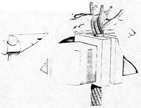
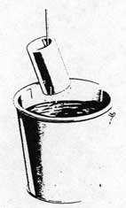
d. Hold the instrument in one hand and immerse the end of the iron rod in the molten zinc, making certain that it is held in the center of the zinc in order to obtain a reading which is representative of the temperature of the whole mass. See figure 5-15. Read the temperature scale.
e. Spare thermocouples are furnished with the pyrometer. They are to be used as replacements when sufficient corrosion of the wrought iron pipe protecting the tube has taken place to permit molten zinc contact with the thermocouple proper. This condition may be determined by visual inspection.
5-41. TEMPILSTIKS. These temperature indicating devices are included in the same carrying case with the portable pyrometer and are to be employed in the measurement of the terminal temperature. The temperature of the terminal is measured as it is being heated with the blow torch. The "Tempilstik" when rubbed against the heated terminal will leave a liquid mark at 400° F. Below this temperature, the "Tempilstik" will leave a chalk mark on contact.
5-42. POURING PROCEDURES FOR CATAPULT TERMINALS. The following procedures for pouring catapult terminals shall be adhered to and no deviations from this procedure are authorized.
5-43. PREPARATION OF THE WIRE ROPE. The following are the steps of procedure for preparing the wire rope:
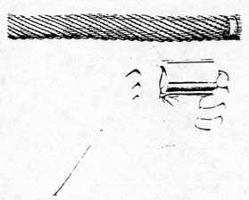
a. If it is necessary to cut the wire rope, place two seizings of eight or ten turns of soft iron wire approximately 1 inch apart and cut between seizings.
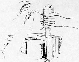
b. Make a seizing of fifteen or twenty turns of soft iron wire at a distance from the cut end equal to the length of the terminal plus 1/4-inch as shown in figure 5-2.
c. Remove the seizing at the cur end, unlay the strands of the wire rope, and carefully straighten out the lay of each individual strand by hand as shown in figure 5-3.
Note
The use of pliers or any other tool for straightening is forbidden as this may damage and weaken the wires.
d. Remove the hemp center of the cable to a distance
66
Figure 5-2. Locating the Seizing
Figure 5-3. Unlaying the Strands
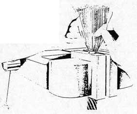
Figure 5-4. Brooming-Out the Wires
from the cut end equal to the length of the terminal plus 1/2-inch.
e. Repeat the unlaying operation on each individual strand, working on one at a time until the wire rope is completely broomed out as shown in figure 5-4.
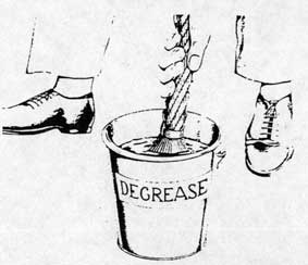
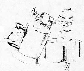
f. Thoroughly and carefully wash the broomed-out end of the wire rope in a bath of carbon tetrachloride, benzene, clear gasoline (not leaded), or an equivalent volatile grease solvent as shown in figure 5-5. All tar, grease, oil, or dirt must be washed off the wire rope. Keep the surface of the carbon tetrachloride bath free of grease and dirt. Remove any scum that collects on top. If the bath becomes dirty, change it for a clean one.
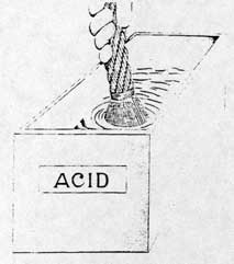
g. Prepare a 50 percent solution of hydrochloric acid (muriatic acid) by using equal volumes of concentrated hydrochloric acid and fresh water. Mix acid solution in a rubber container. Do not use a metal bucket.
CAUTION
When diluting concentrated acid, add acid to water, never water to acid.
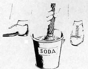
h. Prepare a slightly alkaline solution by dissolving one pound of washing soda (Sodium carbonate) in a bucket of hot water. Do not use washing powder or soap flakes.
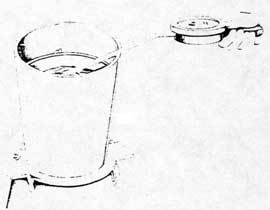
i. After the wire rope strands have been thoroughly degreased, dip the broomed-out wire rope in the acid solution as shown in figure 5-6, in order to remove any scale which might be present, and to provide a chemically-clean surface to which the zinc can cling. Do not immerse deeply enough to allow the hemp center of the wire rope to touch the acid. This center will act as a wick and draw the solution up into the wire rope, thus weakening it. Keep wire rope immersed in the acid for 1 minute.
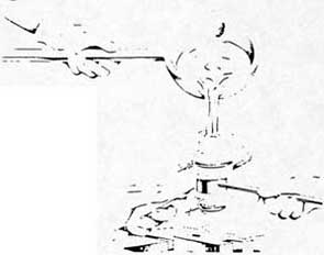
j. When removing the wire rope from the acid bath, be sure to hold it with the broomed-out end down and lower than the rest of the wire rope. The acid solution must not be permitted to run back into the body of the wire rope. To neutralize the effects of the acid bath, immediately after removing the wire rope from the acid solution, wash it thoroughly in the alkaline solution described in sub-paragraph h. Agitate the wire rope vigorously to make sure all parts of the broomed-out end will be washed clean of the acid solution as shown in figure 5-7.
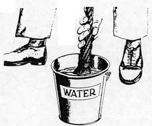
k. Follow the neutralization process by thoroughly rinsing the broomed-out end of the wire rope in clean, hot water as shown in figure 5-8.
CAUTION
After being washed, the wires should be dried in the air. Do not touch the wires with hands, rags, or gloves or the cleanliness required for sound terminals will be impaired.
l. Upon evaporation of the hot water from the wires, check for proper etching. The etching shall be considered adequate when the wires have a dull gray non-reflective finish. If etching is inadequate repeat steps
67
5-43i to 5-43k inclusive until the wires are properly etched.
5-44. PREPARATION OF TERMINAL FOR POURING OF ZINC. The following are the steps of procedure for preparing the terminals:
a. Clean all catapult terminals in the same manner in which the wire rope was cleaned. Wire the terminals to suitable lengths of soft wire and dip, as shown in figure 5-9, in order to avoid contact with acid and prevent injury to the hands.
b. Clamp the wire rope in the jaws of a vise sufficiently tight to hold rope firmly. Do not draw up jaws of vise so hard as to deform the lay of the wire rope. The jaws of the vise shall be covered with wood or a soft metal - such as copper or aluminum - in order to prevent damage to the strands. Do not touch clean broomed-out wires with greasy rags or hands.
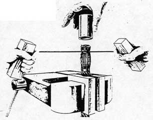
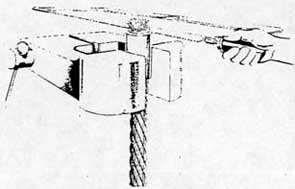
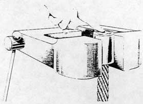
c. Slide the terminal into position on the wire rope until the bottom rests against the seizing. A clean length of soft iron wire - not galvanized or coated - with wooden handles fastened to each end shall be looped over the broomed-out wires, as shown in figure 5-10, and used to squeeze the wires together sufficiently to permit passage of the terminal over the end of the wire rope. The wires should extend approximately one quarter inch beyond the end of the terminal when the terminal is finally in place.
d. Reclamp the wire rope in the vise at a point approximately 5 inches below the seizing in a vertical position so that the terminal is not tilted in any way.
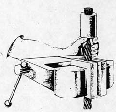
e. Prepare a paste made by mixing powdered asbestos and water to a consistency of putty, and cover the base of the terminal and adjoining wire rope with this preparation to a thickness of about 1/2-inch as shown in figure 5-11.
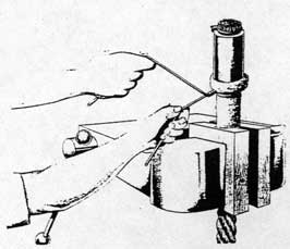
f. Wrap asbestos cloth over the asbestos paste in order to prevent the paste from drying and cracking off when the socket is heated. The asbestos cloth must extend down far enough to protect the wire rope from the blow torch which is used to heat the terminal. Secure the asbestos cloth in place with soft iron wire as shown in figure 5-12.
g. Wrap asbestos cloth around the top end of the terminal and allow it to extend 1/2-inch above the top, securing it in place with several turns of soft iron wire as shown in figure 5-13.
h. Heat the terminal carefully and uniformly with a blow torch as shown in figure 5-14. Make certain that the flame is not directed on the exposed wire rope at the bottom of the asbestos cloth wrapping. After heating for approximately 2 minutes and when the terminal begins to radiate heat waves, make a mark on the terminal with a "Tempilstik". Repeat
Figure 5-5. Degreasing with Solvent
Figure 5-6. Dipping in Acid
Figure 5-7. Neutralizing with Soda
68
Figure 5-8. Washing with Water
Figure 5-9. Cleaning the Terminal
Figure 5-10. Placing the Terminal
every 30 seconds until the "Tempilstik" leaves a wet mark instead of a chalk mark. Check the terminal 30 seconds after obtaining the first wet mark to insure that another wet "Tempilstik" mark is obtained. The zinc should be at a proper temperature at this time so that the pouring can take place within 30 seconds after the terminal is heated to the correct temperature. Do not attempt to measure the terminal temperature with the portable pyrometer. The "Tempilstik" must be used for determining proper terminal temperature.
5-45. PREPARATION AND POURING OF ZINC. While the terminal is being heated, prepare a sufficient quantity of pure, new zinc to pour a complete terminal at one time as follows:
a. Use only grade "A" or "B" zinc, Stock No. G46-Z-500, for pouring terminals. Do not use babbitt metal, solder, or tin.
b. Melt zinc in a clean ladle. The ladle must be large enough to hold sufficient zinc so that a complete terminal may be poured at one time.
CAUTION
Never pour fractional parts of a terminal. Never allow water to come in contact with hot zinc.
c. Skim off the dross from the top of the molten zinc before pouring.
d. Pour zinc at a temperature of 900° F. The temperature of the zinc must be accurately measured with the portable pyrometer. Make certain that the iron rod of the pyrometer is held in the center of the molten zinc as shown in figure 5-15. The zinc may be heated above the pouring temperature but allow it to cool to 900° F. before pouring. This temperature is sufficiently high to insure fluidity so that the molten metal will run down into the bottom of the terminal and between the strands of the wire rope, yet low enough to prevent serious tempering of the wire rope strands.
e. Do not use a flux at any time during the pouring operation or during the preparations for pouring.
f. Pour sufficient zinc into the terminal to provide a "hot top" in order to have a reservoir of molten zinc at the top of the terminal to feed the casting and fill up the shrinkage cavity as it forms in the center of the terminal during cooling.
g. While the zinc is being poured, tap the side of the terminal lightly with a wooden block or screwdriver handle to jar the zinc into the crevices between the wires as shown in figure 5-16. Also tap the side of the terminal lightly while the zinc is solidifying. Never pour additional zinc into terminal to fill up holes or cracks after the zinc has solidified. Repour if necessary.
69
5-46. FINISHING THE TERMINAL. The terminals shall be finished in accordance with the following steps:
a. After the zinc has solidified, allow the terminal to cool in air - do not dip into liquid to speed up cooling - and remove asbestos wrapping and asbestos packing. The terminal is ready for use after it has cooled to the same temperature as the surrounding air.
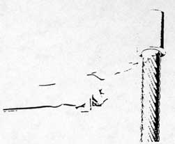
b. Remove the seizing wire at the bottom of the terminal. Cut off the "hot top" flush with the top of the terminal as shown in figure 5-17. When basket-type terminals are poured, make no attempt to crop off the "hot top".
c. Round off the sharp edges of the terminals with a file and file down the zinc to a smooth surface flush with the end of the terminal.
d. Clean the terminal by brushing with a wire brush in order to remove all traces of the asbestos.
e. On threaded terminals chase the threads with a rethreading die.
5-47. INSPECTING THE TERMINAL. After the terminals are finished they shall be thoroughly inspected in the following manner.
a. Inspect the zinc face of the terminal for soundness of zinc as shown in figure 5-18. The presence of any cavities in the face of the zinc indicates that the strength of the terminal is questionable and the terminal shall be repoured.
b. The presence of zinc at the base of the terminal is a good indication of a well-poured terminal as shown in figure 5-19.
c. The wires or the strands of the wire rope below the terminal must not show any signs of deformity due to being held too tightly in the vise during the pouring or finishing operations.
5-48. USE AND CARE OF GASOLINE BLOWTORCH. Gasoline blowtorches, designed for operation with nonleaded fuels, will become clogged upon continuous operation with the high-octane aviation leaded gasoline available aboard carriers. In the absence of nonleaded fuels, satisfactory operation of torches on leaded aviation fuels may be obtained if the burner is kept clean. It is recommended therefore that all torches operated on leaded fuels be cleaned., using the clean-out needle furnished with the torch, immediately after any period of operation. The toxicity of leaded gasoline is a hazard to personnel coming in contact with them if proper precautionary measures are not taken to prevent spilling, or breathing of the fumes. Therefore, torches requiring the use of leaded fuels shall not be drained, filled, or operated in any confined space even though ventilated by ship's forced air. If it is found necessary to pour terminals in undercover spaces where adequate ventilation with outside air is not available or desirable (under cold weather
Figure 5-11. Applying Asbestos Paste
Figure 5-12. Wrapping Asbestos Paste
Figure 5-13. Wrapping Top with Asbestos
70
Figure 5-14. Heating the Terminal
Figure 5-15. Measuring Temperature of Zinc
Figure 5-16. Pouring the Zinc
operations) an oxyacetylene welding torch shall be substituted. Care must be exercised to avoid spilling of gasoline. If leaded gasoline is spilled on the skin, the part shall be washed immediately with soap and water. If spilled on the clothes, they shall be immediately changed and the skin underneath washed in soap and water.
5-49. INSTALLATION OF CABLES. The cables are furnished with the swaged terminals for the shuttle end already attached and of sufficient length to reeve the catapult. Care must be taken at all times to prevent the cable from kinking. The procedure for installing cables is as follows:
a. Set engine crosshead fully retracted.
b. Set cable tensioner crosshead in fully retracted position.
c. Operate equalizer by depressing "REVERSE" button to move equalizer crosshead to its full travel position toward fixed sheaves (until stopped by limit switch), then move crosshead forward 4 inches from this position by depressing "FORWARD" button.
d. Set cable whip damper crossheads in "fully out" position.
e. Set aft end of shuttle 20 inches from aft end of launching track and secure to withstand a pull of 20,000 pounds forward.
f. Reeve towing cables from shuttle to cable whip damper crosshead.
g. Apply a 10,000 pound tensile load to each towing cable simultaneously at the engine end and mark location of socket, NAFACT Part No. 17-4847-1, which will connect the cable to the cable whip damper crosshead. Maintain tension after marking to hold crosshead at battery during marking of retrieving cable.
h. Reeve retrieving cable from shuttle to cable tensioner terminal crosshead. Apply a tension of 10,000 pounds to each retrieving cable simultaneously and mark location of socket, NAFACT Part No. 89588-1, which will connect the cable to the cable tensioner terminal crosshead allowing 20 inches each of additional cable length for proper positioning of tensioner.
i. Release tension. Cut towing and retrieving cables and pour their sockets in accordance with paragraph 5-39. Record exact length of cables required in the catapult log.
5-50. TESTING OF TERMINALS. All sockets and terminals poured on shipboard must be tested for integrity of the poured fitting immediately after installation and before normal operations are resumed in accordance with the following instructions:
a. Remove cable tensioner expansion tank, NAFACT Part No. 18-4360-1, and install test flange, NAFACT Part No. 217473-1, using existing studs
71
and nuts. Connect hydraulic pump, NAFACT Part No. 403309-1, to test flange.
b. Fill system with tensioner fluid to eliminate need for cleaning tensioner after test. Mark the cables at each socket so that any motion of the cable relative to the socket can be measured.
c. The engine crosshead may. be placed in any convenient position. Run shuttle positioner toward the piston valve to remove slack from the cable system. Cable tensioner ram shall be two-blocked in the "fully-in" position.
d. Operate hydraulic pump to increase pressure in the tensioner cylinder in increments of 1000 psi until a pressure of 10,000 psi has been reached. Hold pressure at each increment until the cable sockets or terminals have been thoroughly inspected.
Note
The cable tensioner ram may two-block in the "fully-out" position before maximum test pressure is reached. If so, decrease pressure to 0, move shuttle positioner toward piston valve until the cable tensioner ram is again two-blocked in the "fully-in" position and repeat test.
e. Relative motion between the cable and socket shall not exceed 1/16-inch and no wire rope strands shall be pulled below the surface of the zinc. Faulty fittings shall be repoured and retested.
f. Release pressure slowly. Remove hydraulic pump, piping, and test flange and reinstall the tensioner expansion tank and required fluid.
g. The test equipment necessary for performing the test outlined above will be furnished by the Naval Air Material Center on the basis of one set per ship.
5-51. COMPENSATING FOR CABLE STRETCH.
5-52. After satisfactory completion of terminal tests and with 800 pounds psi tensioner pressure acting, operate shuttle positioner to locate aft end of shuttle 20 inches from aft end of launching track. This may necessitate running the shuttle positioner to its full travel position toward the fixed sheaves. Tensioner crosshead will be approximately 20 inches out from its "fully in" position. During the first few shots with a new cable it stretches appreciably but then becomes seasoned and subsequent shots produce little additional stretch. During this seasoning period the shuttle must be positioned frequently to compensate for towing cable stretch. The retrieving cable stretch will be compensated for automatically by movement of the tensioner crosshead. After the seasoning period and with the shuttle properly positioned, the tensioner crosshead should be approximately in the midposition of its stroke. Should the
Figure 5-17. Sawing Off the "Hot-Top"
Figure 5-18. Inspecting Face of Terminal
Figure 5-19. Inspecting Bottom of Terminal
72
retrieving cable stretch be sufficient to locate the tensioner crosshead at the start of a launching so that the tensioner piston two-blocks at the outer end of the cylinder during the launching, thereby permitting slack in the drive system, the retrieving cable must be shortened as necessary to reposition the tensioner crosshead to its midposition. This shortening is most easily accomplished by cutting the cable and relocating the socket at the tensioner end. Shortening of the towing cables will be necessary only if it becomes impossible to properly position the shuttle with the positioner crosshead at the full limit of its travel toward the piston valve. After thorough seasoning of the cables, the necessity of positioning the shuttle between successive launchings should become infrequent as satisfactory operation is assured with the shuttle located at approximately the position noted, care being required only to see that the shuttle does not reach the aft end of the track during retraction. When installation and testing are complete, paint the cables at the sockets as an aid in determining any future cable slippage from the socket.
5-53. PUMPS.
5-54. CHECKING CAPACITY OF POWER PLANT PUMPS. The approximate capacity of power plant pumps is determined as follows:
a. To determine the capacity of launching power plant pumps set the launching accumulator liquid level at 5 inches in middle gage with an air charge of over 2500 psi. Operate one pump for 60 seconds. Record the change in liquid level after it has stabilized. Repeat this test for each pump to be checked. The pump capacity (GPM) will be 12.23 times the recorded change (inches) in accumulator liquid level.
b. To determine the capacity of retracting power plant pumps, set the retracting accumulator liquid level so that a liquid level rise of about 10 inches can be measured. The accumulator pressure shall be about 850 psi at the upper limit of level rise. Operate one pump for 20 seconds. Record the change in liquid level after it has stabilized. Repeat three times and record average value. Repeat this test for each pump to be checked. The pump capacity (GPM) will be 18.0 times the recorded change (inches) in accumulator liquid level.
c. Pumps shall be replaced as required to maintain a minimum of 75 percent of total rated power Plant capacity or sooner if dictated by operational requirements of the catapult. In any case, an individual unit shall be replaced when its capacity drops to ??? percent of rated capacity. It should be recognized that a loss of pump capacity is not necessarily due to pump rotating unit deficiencies alone, but can also result from delivery control valve malfunctions as well.
5-55. GENERAI MAINTENANCE OF CATAPULT PUMPS. Each ship is furnished with "Operation and Service Handbooks" for the catapult pumps installed. The servicing and maintenance of pumps shall be in accordance with the applicable handbooks. The following list of pump handbooks is given for reference:
2. Oilgear Co. Type HG-830 ... No Handbook. See Oilgear Co. Dwg. No. DS-946400
d. Drain Pumps
1. Viking Model ZHJH Dwg. BA-950 ... W. H. Eagan Publication No. 1
2. Worthington Type 1 1/2 GRS ... No Handbook. See McKiernan & Terry Dwg. No. SL-5478.
5-56. VENTING PUMPS AND CLEANING PUMP SECTION LINES. If air is present in the pump or the pump suction line is obstructed (See Section VI - Malfunctions) the following steps shall be taken. Run the pump intermittently, turning the motor on and off at intervals of about 10 seconds to vent the suction line and work the air out of the pump. If the excessive pump noise diminishes gradually, continue venting until all air has been worked out. If venting does not reduce the pump noise, the suction line must be checked for an obstruction. The most likely causes of an obstruction would be either a clogged strainer or a suction line restriction.
5-57. ELECTRICAL COMPONENTS.
5-58. Sufficient spares have been provided so that there should be no necessity of attempting any intricate repair of an electrical component. If any electrical unit is found to be defective it shall be replaced immediately and no attempt at repair shall be made by shipboard forces. Modification of any electrical component shall not be done except by express authority of a catapult change. Relays shall not be lubricated. See paragraph 5-9i for maintenance of relays.
5-59. SOLENOID VALVE MAINTENANCE. Other than periodic cleaning and lubrication, solenoid air valves should operate indefinitely without maintenance. The principal point for accumulation of deposits in a solenoid will be found to be the core tube and special attention shall be given this area in cleaning. In general, if the current supply is correct, sluggish action indicates that cleaning is required.
73
Only the air end of the solenoid shall be disassembled for cleaning and necessary lubrication. If failure of the solenoid valve is due to a defect in the core or coil (electrical end), the valve shall be immediately replaced. Operating pressures must not exceed the pressure stated on the name plate. In replacing valves, pipe strain on the valve must be eliminated by having piping properly supported and aligned, and electrical connections must be made to line of proper voltage and frequency as specified. Abnormally high or low voltage may cause overheating of the coil since the current flow with a given voltage is considerably greater with the core down (de-energized) than it is when the core is up. Excessive pressure or jamming of the mechanism may cause overheating since unless the core is free to move to its proper position when it is energized the normal current will be exceeded and the coil will burn out. Solenoid valves are designed to be quickly and easily cleaned without the necessity of removing the valve from its pipe lines. Lubricating oil used in the air end of the solenoid valve shall be Navy Symbol No. 2190.
5-60. PULLING OUT CROSSHEAD.
5-61. To pull the crosshead out for any necessary maintenance or repair, attach the towing cable to the shuttle ramp. Before attempting to pull out the crosshead with the deck tractor reduce the cable tensioner dome pressure and the cable whip damper dome pressure to 400 psi.
5-62. CHECKING SLOT ALIGNMENT IN BYPASS VALVE.
5-63. It has been determined that one of the reasons for premature braking of the catapult engines is improper alignment of the slots in the body of the bypass valve. In order to prevent the considerable damage which could result from premature braking, the slots of the plug must be correctly aligned and the alignment shall be checked daily by means of the matching marks placed - after correct alignment - on the plug shaft and on the packing gland of the valve. In order to check the slot alignment the following alignment Procedure is carried out
a. The catapult shall be secured, the retracting accumulator air charge blown off, and the fluid drained from the brake cylinder. Remove the section of the line from the retracting gravity tank to the bypass valve by breaking the two flanges and disconnecting, at a convenient union, any other lines necessary to move this section. With this 6-inch Line from the retracting gravity tank removed, room is provided for determining by hand the alignment of the slots.
b. The ideal condition is with both slots exactly aligned as shown on NAFACT Drawing No. 314618.
However, misalignment may result when assembling the flexible coupling. This misalignment is allowable only to a maximum of 1/8-inch between slots but mast always be with the slots in the plug misaligned in the opposite direction from the operating rotational direction of closing of the plug as shown on NAFACT Drawing No. 314618. If the alignment of the sluts is correct within the above limits, no further action is necessary and the pipe line may be reconnected after removing and discarding old gaskets and replacing with new.
c. If, upon checking slot alignment as above, it is found that the slots in the plug are misaligned in the direction of operating rotation, the following adjustments must be made to correctly realign the slots.
1. Disassemble the flexible coupling. Rotate the plug of the bypass valve counterclockwise to realign the slots as required and reassemble the coupling.
2. Check the setting of the mechanical controls as follows: with low-pressure air on and with the crosshead in fully retracted position, mount braking cylinder support, NAFACT Part No. 602906-1, on tracks and slide forward until cam on support makes contact with crank assembly roller of controls. At the point of contact, the controls should be set as shown on NAFACT Drawing No. 24-6725.
Note
Before using the braking cylinder support to set the controls, it should be checked against the cam on the crosshead to determine that both are exactly the same height at their corresponding high and low points. Measurements shall be made from a fixed point on the deck.
3. With the low-pressure air on, depress the "RETRACT" button and hold it depressed. Slide the support forward until the low surface of the cam is over the roller and measure the clearance between the bottom of the cam and the top of the roller. There should be 1/4-inch clearance at this point and the actuator on the forward lever assembly should have reversed the limit switch contacts. Any deviation from correct setting of the controls may be adjusted by means of the turnbuckle in the rod between the lever and crank.
4. After the slots have been correctly aligned, scribe or punch matching marks on the plug shaft and on the packing gland of the valve so that correct alignment can be checked prior to each day's operation. See paragraph 5-8j.
74
5-64. LEAKING HIGH-PRESSURE SHUTOFF VALVES.
5.65. Hand pressure alone should be sufficient to make the valve tight. When a valve can no longer be shut tight replace the valve seat, valve disk, and stem packing with new parts furnished in valve repair kits, NAFACT Drawing No. 402082.
5-66. BRIDLES AND PENDANTS.
5-67. This section contains general instructions for the inspection and maintenance of the bridles and pendants which are employed in conjunction with the different types of aircraft which are launched from hydraulic catapults. The launching accessories for the different types of airplanes will continue to be obtained from the current H8 Catapult Bulletins pertaining to the plane to be launched. The following are some general instructions for use of bridles and pendants.
a. Stowed bridles shall be coated liberally with graphite grease, Specification MIL-G-7187, to prevent corrosion.
b. The bridles shall be inspected for broken wires after each launching. If more than two wires are broken, the bridles should be replaced.
c. When using double cable bridles, be certain both cables are engaged under the lip of the shuttle towing hook.
d. Make sure the correct bridle is being used to launch each plane.
e. There must be enough bridle tension at full engine thrust to remove excessive slack. This will prevent bridle from disengaging from hooks. It will also prevent overloading of bridle at start of launching.
5-68. LIQUID LEVEL GAGES.
5-69. The fluid used in the catapult contains a red dye to facilitate reading of liquid level gages. If the gages become clogged or if condensation causes colorless fluid to settle in the top of the gage glass the gages must be cleaned. To clean the gages shut off the lines with valves provided and disconnect the lines between the valve and the gage. Blow out the line and gage with low-pressure air. If blowing out does not completely clean the gages, they shall be disassembled and cleaned.
5-70. DETAILED CORRECTIVE MAINTENANCE PROCEDURES.
5-71. PISTON VALVE.
5-72. FLUID LEAKAGE AT VALVE SECURING STEM.
If fluid leakage is noted at valve stem the O-ring must
be replaced since this is a running seal and only replacement of the O-ring can correct the leakage. To replace the O-ring the vent to the securing stem chamber (Chamber "B") and the vent to the chamber outside the threads must be opened. Remove the six bolts and lock-washers holding the cover to the large head and slip the cover back over and off the valve stem. Check the surface of the valve stem for roughness. Hone any apparent rough spots. Remove and discard O-ring between cover and head. Remove and discard O-ring between cover and stem. Clean the groove and the mating surfaces of the head. Clean cover with particular attention to O-ring groove. Check bore of cover and hone any rough spots found. Lubricate and insert the two new O-rings. Slide cover over stem up to head. Check mating of cover and head to insure that there is correct contact of the mating surfaces. Rework or replace parts as necessary to gain a proper contact. Replace six bolts and lock-washers and tighten evenly.
5-73. LEAKAGE BETWEEN COVER AND LARGE HEAD. If leakage is noted between cover and large head the first step is to check the six bolts holding the cover to the head for proper tightness. If correcting the torque of the bolts does not completely stop the leakage the cause of the leakage must be determined and corrected. The possible causes of this leak are a loose joint, misalignment, or excessive clearance. Where misalignment or excessive clearance exist the parts must be repaired or replaced. To replace the O-ring gasket between the cover and large head the vents at chamber "B" and at outside the threads must be opened. Remove the six bolts and lockwashers holding the cover to the large head and slide the cover back along the valve stem. Remove and discard old ring. Inspect mating faces for evidence of misalignment and consequent faulty contact. Rework or replace parts as necessary to gain a proper contact. Clean mating faces with special attention to packing groove. Remove and discard O-ring between cover and stem. Lubricate and insert two new O-rings. Slide cover back to head and replace six bolts and lock-washers. Tighten bolts evenly.
5-74. FLUID LEAKAGE BETWEEN LARGE HEAD AND BODY OF PISTON VALVE. Leakage detected at this point may be caused by a failure of the O-ring gasket, a loose joint, improper contact of the mating surfaces, or excessive clearances. Check for proper tightness of the twenty nuts around the flange. If leakage persists, the valve must be disassembled to correct the leakage. Blow the accumulator fluid level down below the level of the piston valve, and blow the air charge off. Close the gate valve in the engine return line to the gravity tank and pull the crosshead out to drain the return line. Unscrew the securing stem, remove the plug from the small head of the valve, insert a rod,
75
NAFACT Part No. 15-2382-1, and carefully jack the piston valve full open to drain the valve and the elbow into the manifold. Rig suitable tackle to support the 565 pound weight of the head using an eyebolt, threaded 3/4 - 10, inserted into the hole provided. Remove the twenty nuts and lockwashers. Carefully withdraw the head directly away from the valve, since the inner side of the head surrounds the poppet. Remove and discard the old O-ring. Check mating diameters of the head and body for proper clearances. Check interior portions of head and poppet. Check lockwires on disc. Check studs for tightness. Check rings on poppet for excessive wear and proper direction of installation. Smooth up nicks and burrs. Lubricate new O-ring and install on head. Reassemble head onto valve and poppet, compressing rings carefully. Seat head against body, replace the twenty lockwashers and nuts, and tighten evenly. Remove rod and replace plug. Turn securing stem in to close valve. Open gate valve in gravity tank return line and refill elbow, piston valve, and engine cylinder. Retract catapult and take on air charge in launching accumulator. Vent catapult thoroughly to insure that system is completely filled with fluid. Vent piston valve thoroughly.
5-75. FLUID LEAKAGE BETWEEN SMALL HEAD AND ADAPTER. A fluid leak at this location would be caused by failure of the O-ring gasket, lack of full contact between small head and adapter, excessive clearances, or a loose joint. To correct this leakage first check for proper, even tightness of the eight bolts holding the head and adapter to the body. If leakage persists, the valve must be partially disassembled to correct the leakage. Before disassembly the fluid level shall be blown down below the level of the poppet, the gravity return line shall be closed by means of the gate valve, the launching accumulator air charge blown off, the crosshead pulled out to drain the elbow, and the valve drained at the end cap. At the top center of the head will be found a 3/4-inch hole for the eyebolt used to lift off this head weighing approximately 110 pounds. Remove the bolt under the tapped hole before inserting the eyebolt as the tapped hole is centered over this bolt and bottoming the eyebolt on insertion would jam the bolt and prevent its removal. Remove the remaining bolts and free the head from the adapter. Remove and discard the old O-ring gasket. Check the mating diameter of the head and adapter for proper clearances. Correct to obtain proper clearances by grinding or replacement of parts. Completely clean interior surfaces of head and any ocher accessible portions of the valve. Lubricate new O-ring gasket and place over head. Replace head, lockwashers, and nuts and tighten evenly. Open the valve, retract catapult, insure that the system is filled with fluid, and take on air charge.
5-76. FLUID LEAKAGE BETWEEN ADAPTER AND
BODY. As in all static seals using O-ring gaskets a leak may be caused by failure of the O-ring gasket, improper contact of the mating parts, excessive clearances, or a loose joint. Check first for proper even tightness of the eight bolts holding the small head and the adapter to the body. If leakage still persists, blow down the fluid level below the poppet of the valve piston, close the gravity return line, blow off the launching accumulator air charge, pull crosshead out, drain all fluid from the valve, and proceed to disassemble this part of the valve. Remove the head as detailed above. Remove piping to firing operating valve. Remove the cotterpin securing the pin holding the nut on the rod. Discard cotterpin. Remove nut pin. Remove the rod nut and its washer. Remove the piston. Inspect the piston for signs of undue wear. Replace if necessary. If piston is reusable other than for minor rough spots or minor corrosion; hone rough spots, remove any corrosion, and clean. Remove adapter. Remove and discard old O-ring gasket. Clean adapter completely and check clearances between adapter and body. Check bore of adapter for wear. Correct clearances if necessary or replace adapter if excessively worn. Lubricate new O-ring gasket and place over adapter. Replace piston, rod nut and its washer. Replace nut pin. Install new cotterpin. Insert new O-ring gasket between head and adapter as detailed above. Replace, head, lockwashers, and bolts and tighten evenly. Bring fluid and air charges back to normal levels. Fill elbow and piston valve before making launchings.
5-77. FLUID LEAKAGE BETWEEN FLANGE OF PISTON VALVE AND MANIFOLD. The causes of this leak would be as mentioned above for other applications of this static seal O-ring. If checking tightness of the bolts does not stop the leakage the joint must be disassembled and the cause of leakage determined and corrected. Before breaking the flange joint the catapult shall be secured, the fluid level blown down, and the launching accumulator air charge blown off. The valves controlling the flow of fluid from the launching pump units shall be closed. For draining, the launching accumulator shall be vented and the fluid drained from the accumulator and manifold by means of the drain plug located on the bottom of the manifold. The line from the manifold to the liquid level gages shall then be uncoupled at any convenient coupling. The Line from the manifold to the shutoff valve shall be uncoupled. The lines from the pump units to the manifold shall be uncoupled between the shutoff valves and the check valves. Provision must be made, by means of blocking or jacking, to lower and hold the manifold which weighs approximately 2500 pounds. With the manifold rigged for lowering, the bolts securing the manifold to the piston valve and to the launching accumulator shall be removed. Inspect the mating surfaces of the manifold, of the piston valve, and of the launching
76
accumulator. Correct any defects found. Remove and discard both old O-ring gaskets. Clean all flanges and clean and flush interior of manifold- Replace manifold drain plug. Lubricate and insert new O-ring gaskets. Both gaskets shall be replaced even if only one has shown leakage. Replace manifold and tighten all bolts evenly. Reassemble all uncoupled connections. Return all valves to normal operating position and fluid and air charges to normal levels.
5-78. FLUID LEAKAGE BETWEEN ENGINE CYLINDER ELBOW AND PISTON VALVE. Check tightness of bolts around flange. If leakage persists the joint may be broken by the following procedure:
a. Blow down both accumulators. Vent catapult and drain fluid below engine cylinder elbow level.
b. Running into the line from the elbow check valve to the gravity tank will be found the vent line running from the firing operating valve. Uncouple this line at the first union. Remove the nuts, bolts, and lock-washers from the flange at the elbow check valve for the line running to the gravity tank and remove the nuts, bolts, and lockwashers for the next flange on this same line. Lift out this section of pipe. Remove and discard both fiber gaskets. Clean flange faces. Protect openings of line and valve against entry of dirt.
c. Remove the eight nuts and lockwashers holding the 4-inch line to the flange of the air trap cylinder. If there is not sufficient play in the electrical connections to the limit switch, the switch shall be removed and secured out of the removal path of the air trap cylinder. Do not break the electrical connections unless necessary. Break electrical connection to auxiliary firing switch located on top of elbow check Valve. Disconnect lines from four-way valve to elbow check valve. Remove nuts and lockwashers holding engine cylinder elbow to engine cylinder. Remove bolts holding engine cylinder elbow to piston valve. Pull crosshead out several feet. Disconnect blowdown line if necessary. Move engine cylinder elbow with attached elbow check valve and air trap cylinder off of piston valve and away from engine cylinder. Protect openings into engine to prevent entry of dirt. Withdraw directly away from main engine cylinder to avoid damage to cylinder studs.
d. Remove and discard old O-ring gasket from engine cylinder elbow. Remove and discard old O-ring gasket from flange of air trap cylinder. Remove and discard old O-ring gasket from bottom flange of engine cylinder elbow. Check mating of engine cylinder elbow and piston valve. Correct excessive clearances or mismated surfaces and clean. Lubricate and install new O-ring gasket in bottom flange of engine cylinder elbow.
e. Lubricate and install new O-ring gaskets on cylinder flange of
engine cylinder elbow and flange of air trap cylinder. Position elbow and air trap cylinder and replace bolts holding elbow to piston valve, nuts and lockwashers holding elbow to cylinder, and nuts and lockwashers holding air trap cylinder to flange. Tighten all fastenings evenly. Mount limit switch on air trap cylinder by means of the four bolts with their nuts and lock-washers. Reconnect electrical and air line connections to elbow check valve. Replace section of line from elbow check valve to gravity tank, installing two new fiber gaskets. Rejoin the coupling in the line from the firing operating valve.
f. Replace all drain plugs and close vents.
g. Return fluid and air charges to normal levels.
5-79. BINDING. If a "slow shot" is observed (see Section VI - Malfunctions) one of the causes for this malfunction could be a binding of the piston valve. The cause of binding may be determined only by disassembly of the valve. The valve may be disassembled in the following manner:
a. Blow down launching accumulator air charge, vent, and drain valve fluid to below level of poppet.
b. Disassemble valve as detailed in paragraphs 5-74, 5-75, and 5-76. With these steps accomplished, remove the poppet assembly through the securing stem end of the valve. Note any abnormal resistance to movement during disassembly and any indications of binding of moving parts. Check for obstructions, dirt, or any foreign matter in valve. Examine all parts of valve for burrs, chips, cracks, or any roughness of surfaces. Examine minutely all mating surfaces for evidence of scoring or binding. Examine welds of poppet for possible failure of weld causing misalignment. Check all clearances against required clearances shown on applicable drawings. Particular attention shall be paid to the quality of the lapping of the poppet and the bushing. If cause of binding cannot be corrected, the valve shall be replaced. Replacement procedure would be essentially the same procedure used for replacing the gasket between the valve and the manifold of the old valve and installing the new one. If binding is located and the cause corrected, the valve shall then be reassembled.
c. Completely clean the interior of the valve body. Whenever a joint has been broken discard all old gaskets and select new ones of correct size for use. All parts of the valve shall be clean before reassembly with all corrosion and rough spots removed.
d. Place O-ring over adapter and assemble adapter to body of valve. It may be found necessary to use temporary bolts to hold the adapter in place unless blocking can be accomplished.. Insert piston into adapter. Place poppet in valve body and pass piston rod through piston. Be sure that washer is on piston rod at end of piston. Place large washer over rod to lie between piston and nut. Tighten nut, insert pin, and secure with new cotterpin.
77
e. Push poppet out toward stem end of the valve. Insert O-ring in inner end of large head. Pass inner end of large head over poppet rings making sure that rings are properly compressed. Assemble large head to body.
f. Remove temporary bolts, if used, from adapter. Mount O-ring over small head, assemble small head to adapter, and bolt to body.
5-80. AIR TRAP CYLINDER.
5-81. DISASSEMBLY OF AIR TRAP CYLINDER. In most cases, except for leakage between the cylinder and clapper valve or elbow check valve, it is not necessary to remove the air trap cylinder from the elbow check valve. Close the gate valve in the gravity tank return line and pull the crosshead out several feet to lower the fluid level. Disconnect the 4-inch line at the air trap cylinder and at the constant pressure valve, loosen the support brackets, and slide the entire line toward the constant pressure valve. Disassemble the air trap cylinder as described in paragraph 5-83. Reassemble in reverse procedure and fill system completely before making launchings.
5-82. FLUID LEAKAGE BETWEEN FLANGE AND CYLINDER AT PISTON END OF CYLINDER. Leakage cannot be corrected by tightening nuts of retainer and the cylinder must be disassembled and the leakage corrected. Disassemble and check as for other static seals and replace O-ring by slipping over retainer flange and reassemble.
5-83. FLUID LEAKAGE FROM WEEP HOLES AT END OF ROD. This leakage will be an indication of the failure of the one or both sets of piston packings. The correct procedure is to replace both sets of packings even though only one is defective. Since the piston packings are spring-loaded it is not possible to correct leakage by tightening of the retainers and the packing rings must be replaced. Retainers, adapters, or springs need not be replaced unless they are defective. Replacement of piston packings requires removal of the piston and withdrawal of the rod. Since an attempt at reassembly by pushing the rod back through the packings at the bracket end of the cylinder would probably result in damaging these packings they must also be replaced. Further, since the possibility exists that the piston packings and the O-ring packing of the rod at its piston end may have failed simultaneously, good corrective maintenance procedure demands that this rod packing be replaced whenever the piston packings are replaced. The piston shall be withdrawn from the cylinder with its attached rod. The bracket shall be removed by taking off the four nuts and lock-washers holding it to the cylinder and the rod packings shall then be removed by backing out the retainer with the special wrench provided. The packings shall
be discarded but the spring and adapters may be reused if not damaged. Check adapters and retainers for burrs or roughness and correct if found. Remove and discard the piston V-ring packings by removing the bolted retainers. Inspect adapters and retainers for burrs or roughness. Clean interior of cylinder, inspect finish, and correct defects found. Remove bolts and draw rod out of piston. Inspect rod for burrs or scratches and remove any found. Remove old O-ring from rod end of piston, insert new O-ring, and replace rod in piston by replacing the four bolts and installing new lockwire. Check piston drain holes and rod to make sure that escape passage for fluid is clear. Install female adapters and two new sets of five packing rings each on the piston. Make sure that open ends of packing rings face away from each other and toward the ends of the piston. Install packings, without cutting, one at a time. Install male adapters and retainers with springs. Tighten bolts holding retainers only enough to seat the retainers firmly against the piston. Packings are spring-loaded and excessive tightening of retainer bolts will not further compress the packings but may damage the retainer. Insert rod and piston into cylinder and push in until rod just clears the bracket end of the cylinder. Install spring, male adapter, new packing of five rings, female adapter, and retainer over rod. Replace bracket, aligning it by means of two dowel pins and replace and tighten four nuts and lockwashers. Reassemble air trap cylinder to elbow check valve and replace electrical connections if broken.
5-84. FLUID LEAKAGE BETWEEN BRACKET AND CYLINDER. This fluid leakage would be the result of failure of the V-ring packing of the rod at the end of the cylinder. In this particular case it will be possible to replace the packing without a major disassembly of the cylinder. Disconnect the limit switch and remove the bracket by backing off the four nuts holding the bracket. Back out the packing retainer and remove the packing. Install five new packing rings over the rod as solid rings and replace retainer. Do not force retainer. Packings are spring-loaded and are not compressed by the retainer. Replace bracket with four nuts and lockwashers and connect limit switch.
5-85. FLUID LEAKAGE BETWEEN AIR TRAP CYLINDER AND CLAPPER VALVE OR BETWEEN CLAPPER VALVE AND ELBOW CHECK VALVE. Tightening the nuts holding the cylinder and clapper valve to the elbow check valve will not correct this leakage and the air trap cylinder and the packings must be replaced. Remove the nuts and lockwashers holding the air crap cylinder and clapper valve to the elbow check valve. Clean all accessible parts and inspect for burrs, cuts, or roughness. Discard oil O-rings and insert new. Reassemble by slipping new O-ring over adapter and inserting adapter into elbow check valve. Slip other new O-ring
78
over flange of air trap cylinder, check orifices of valves for obstructions, insert valve into air trap cylinder making sure that spring is in place, place air trap cylinder in position, and replace nuts and lockwashers. Check shim between cylinder flange and adapter to make sure that seat has correct contact with adapter. If contact is not correct, shim to suit.
5-86. CLAPPER VALVE.
5-87. BENDING. Disassembly to check for binding of clapper valve is the same as disassembly for replacement of packings. If binding is suspected, check clearances and look for evidence of scoring or undue wear. Install new packings on reassembly.
5-88. ELBOW CHECK VALVE.
5-89. LEAKAGE AT ACTUATING ROD. Leakage from the gland around the rod will result from the failure of the O-ring in the gland. Remove the auxiliary firing switch above the rod. Close the shutoff valve to the four-way valve and remove the piping connection to the upper side of the check valve piston. Remove the stake holding the rod to the stem and loosen the gland around the rod. Remove the rod and gland. remove the rod from the gland and remove the O-ring from the gland. Clean the gland and install a new O-ring. Examine the rod for scores or sharp edges. Insert rod through gland, turning threaded portion past the O-ring. Thread rod into stem, tighten, stake, and tighten gland. Reconnect piping and reinstall switch. Open shutoff valve to four-way valve and vent elbow check valve at gland. Open gate valve and retract catapult. Vent thoroughly to remove all air from the engine cylinder.
5-90. LEAKAGE OF INTERIOR PACKINGS. Because of the necessity of complete disassembly to replace any interior packing the procedures will be given as one procedure. It is recommended that all packings of the valve be replaced at the same time in order to avoid needless repetition of disassembly. Close gate valve in return line and pull crosshead out several feet. To remove the elbow check valve from its adapter, the line running from the elbow check valve to the gravity tank must be broken at the flange of the valve. Remove auxiliary firing switch and bracket. Close supply valve to four-way valve. The lines from the four-way valve to the elbow check valve shall be disconnected, the openings protected, and the nuts holding the elbow check valve to its adapter may then be removed and the elbow check valve lifted out )f its adapter. Remove and discard the O-ring found on the adapter end of the elbow check valve. Protect the opening of the adapter against entry of dirt. Remove gland from head of valve as outlined in previous paragraph. Remove and discard the single
O-ring packing from gland. Clean gland and check stem for scoring, roughness, or corrosion. Remove the single setscrew from the lower end of the head and turn bead off cylinder. Remove and discard single O-ring found on top of cylinder. Remove and discard cotterpin holding nut on stem and back off nut and remove single washer after blocking stem at disc end so that it does not fall out of valve. Remove the four nuts and lockwashers holding the valve assembly to the elbow and lift off the valve assembly. Remove and discard the single O-ring sealing the valve assembly and the elbow. Remove and discard single O-ring from the lower inner diameter of the valve assembly. Lift piston out of cylinder and remove and discard its single O-ring packing. Cut and discard single O-ring packing on stem. Clean all parts of valve thoroughly and remove any roughness or sign of corrosion. Remove stem and discs, clean and inspect but do not needlessly disassemble. Relap if required. To reassemble insert the stem assembly and block it against its seat. Select correctly sized replacement O-rings and lubricate. Place one new O-ring over rod, down stem, and over step of stem being careful to avoid excessive stretch. Place one new O-ring over lower end of cylinder and insert one new O-ring in lower inside diameter of cylinder. Place cylinder over rod and stem and into elbow and secure with four nuts and lockwashers. Install single new O-ring on piston being careful to avoid excessive stretching. Place piston over rod, down over stem, and insert into cylinder. Replace washer and nut. Install new cotter-pin to secure nut. Install single new O-ring in top of cylinder. Replace head over rod. Replace setscrew. Insert one new O-ring in gland and reinstall as outlined previously. Install a new O-ring on the adapter end of the valve and mount valve to adapter and secure with nuts. Reconnect lines from four-way valve to elbow check valve. Reconnect line to gravity tank and install auxiliary firing switch. Open gate valve and shut off valve to four-way valve. Retract catapult and vent thoroughly, including gland at top of elbow check valve.
5-91. BINDING OR STICKING. If binding or sticking is suspected by reason of failure of stem to drop, the first step is to vent the elbow check valve operating cylinder by means of the vent valve provided. If entrapped air in the operating cylinder is not the cause of the valve's failure to open, the stem shall be checked for binding. The engine shall be secured and the signal system operated to obtain a "FIRE" signal. Blanking the signal system at this point should cause the stem to drop. If stem does nor drop, check stem gland for excessive tightness. If loosening the gland will allow the stem to drop the fault is in the gland itself and the gland and its O-ring packing shall be replaced as above. If loosening the gland does not cause the stem to drop, the valve must be
79
disassembled to check for interior binding. Disassembly to check for interior binding would entail the same procedure as disassembly for replacement of interior packings as given in paragraph 5-90. On disassembly check clearances as shown on applicable drawings and look for evidence of scoring or undue wear. These causes of binding must be eliminated either by reworking or replacement of the affected parts.
5-92. REPLACEMENT OF SWITCH (Do AUX SWITCH). If it is necessary to replace the elbow check valve switch (Do Aux) the new switch must be checked to see if correct spacers have been installed. If new larger spacers are not already installed in the replacement switch use the correct spacers, NAFACT Part No. 314734-2, from the old switch.
5-93. FOUR-WAY VALVE.
5-94. FLUID LEAKAGE. With the exception of exterior leakage at line connections, which may be corrected by tightening or replacing of connectors, there is but one possible source of exterior fluid leakage in the four-way valve. This would be a leakage past the O-ring packing on the floating piston. This leakage will be observable through the inspection hole in the valve. To correct the leakage the O-ring must be replaced. Pressure must be removed and fluid drained from the valve. The line from the four-way valve to its air solenoid valve shall be broken at the coupling. Remove the setscrew from the cylinder and unscrew the cylinder from the body. With the cylinder off, the floating piston is completely free and care must be taken that the floating piston is not allowed to drop and be damaged. Remove and discard the single old O-ring from the floating piston. Inspect floating piston and valve body for corrosion or rough spots and remove any defects found or replace parts if necessary. Remove large piston from cylinder and remove and discard its single O-ring. Clean large piston and cylinder completely removing any corrosion or rough spots found. Install new O-ring in large piston. Insert large piston in cylinder making sure it is correctly seated. Install new O-ring on floating piston and reassemble valve by placing floating piston - smaller end up - in body and threading on cylinder containing large piston. Replace setscrew and connect line to air solenoid valve.
5-95. BINDING. The cause of binding of a four-way valve may be determined by a disassembly procedure identical to the procedure for replacement of packings as given above. The cylinder and large piston shall be checked for evidence of scoring and/or binding and replaced if necessary. If the floating piston cannot be removed easily due to severe binding or if it shows any evidence of excessive scoring on removal,
the whole valve shall be replaced. The large piston and its cylinder must also be replaced if the cause of the large piston's binding cannot be located or eliminated. Replacement of the valve body will require disconnection of the five fluid lines.
5-96. FIRING OPERATING VALVE.
5-97. AIR LEAKAGE. Air leaks in the firing operating valve will be detected easily on inspection during operation. The two possible points of leakage are the fitting of the firing solenoid valve low-pressure line and the packing around the rod of the piston. Leakage at the fitting may be corrected by tightening or replacing the fitting. Leakage past the rod packing will require disassembly of the valve. See following paragraph for procedure of disassembly.
5-98. FLUID LEAKAGE. Fluid leakage at the plug and/or at the ports to the accumulator, the piston valve, and the gravity tanks will be visible leaks and may be corrected by tightening or replacing the fittings. Interior leakage from the high-pressure side can be determined by observing the launching accumulator liquid level over a period of time with the supply valve open. Leakage past the packing of the latch solenoid end of the piston will be apparent visually. Slight leakage past the packing on the rod end of the piston will show at exhaust valve port. Excessive leakage might result in failure of the valve to close at cutoff and a broken cutoff linkage. To disassemble the valve, the supply valve to the firing operating valve must be secured, the gate valve in the gravity tank return line closed, and fluid drained from the lines. The clevis terminal on the end of the rod shall be removed by removing its pin and taking out the single setscrew bolding it to the rod. The terminal may then be unscrewed from the rod. The piston is removed by pushing it through and out of the valve body. The single O-ring packing found in the valve body at the rod end shall be removed and discarded. The piston has a single O-ring at each end and these shall be removed and discarded. The piston shall be completely cleaned and checked for damage or binding. The interior of the valve shall then be inspected and cleaned. Install two new O-ring packings on piston. Insert piston into valve body and check for alignment. Push piston through valve body till rod approaches packing groove and then insert a single new O-ring packing in groove. Care must be taken not to cut or otherwise damage the ring when the piston rod is pushed through. Thread terminal on rod, insert and stake setscrew. Recouple terminal.
5-99. SLUGGISH OPERATION OR NONOPERATION. If sluggish operation or nonoperation is noted, the first check shall be for external causes such as binding of
80
mechanical linkage or failure of lock pin to lift. Possible losses of air or fluid pressure shall then be investigated including failure of packings or obstructions in the air or fluid lines. Before disassembly the valve and the engine shall be secured, the supply valve closed, the valve in the gravity return line secured, the gravity return line drained, and the terminal connection broken. If no cause of nonoperation is found the valve shall be replaced. All air and fluid connections shall be broken and the old valve taken off by removal of the four bolts holding, it to the support. Recheck linkage adjustment. Insure that throttling nipple is installed at supply port.
5-100. ENGINE CYLINDER AND ENGINE CYLINDER ELBOW.
5-101. FLUID LEAKAGE. Leakage at this joint will be caused by improper contact of the two mating surfaces or failure of the gasket. Taking up on the nuts securing the joint cannot correct the leakage and the joint shall be broken and the O-ring gasket replaced. To break the joint the engine cylinder elbow shall be removed as previously detailed in paragraph 5-78. With the engine cylinder elbow with attached elbow check valve and air trap cylinder removed, the old O-ring basket shall be removed from the engine cylinder elbow and discarded. The mating surfaces of the engine cylinder and the engine cylinder elbow shall be inspected for excessive clearances, correct concentricity, and finish and shall be reworked or replaced as necessary. Studs shall be checked for looseness or misalignment and corrected as necessary. To reassemble, clean all accessible surfaces of the two assemblies and lubricate and insert a new O-ring gasket. The engine cylinder elbow shall then be mounted to the engine cylinder by replacement and tightening of the nuts with their lockwashers. Tighten nuts evenly in rotation. On reassembly, install new packings at all joints broken in disassembly. Replace and tighten evenly the bolts holding engine cylinder elbow to piston valve and bolts holding the flange of the air trap cylinder to the 4-inch line. Mount limit switch on air trap cylinder. Rejoin electrical and air connections to elbow check valve. Replace section of line from elbow check valve to gravity tank, installing two new fiber gaskets. Reconnect the coupling in the line from the launching operating valve. Replace the coupling in the line from the launching operating valve. Replace all drain plugs and close vents. Return fluid and air charges to normal levels.
5-102. ENGINE CYLINDER AND RAM.
1-103. FLUID LEAKAGE. Excessive leakage at this joint will be the result of packing failure. Bolts holding the packing gland should not be tightened excessively in an attempt to correct leakage. Replacement
of packings is a simple procedure and is the only correct method for stopping the leakage. To remove the five old V-ring packings with their spacer and follower the engine shall be secured, the gravity return line closed, and the main engine cylinder drained. The ram shall be moved out of the cylinder by pulling out the crosshead to give the needed working space. To pull out the crosshead, first reduce the cable tensioner dome pressure and cable whip damper dome pressure to 400 psi. The lockwire shall be removed from the heads of the bolts holding the gland to the cylinder and the gland with its attached collars and its contained wiper shall be drawn back along the ram after removal of the bolts holding the gland to the cylinder. The packing follower shall be drawn out of the cylinder by inserting a soft metal rod (threaded 10-32NF-3A) into any of the four tapped holes provided in the follower. It may be found necessary to use more than one rod to remove the follower. The two sets of removal holes are diametrically opposite each other. With the follower removed the packing may be removed with a U-shaped piece of soft rod formed into hooks at its open end. With the five rings of split packing completely removed the spacer may be removed in the same manner and by means of the same tool used for removal of the follower. The ram shall be inspected as completely as possible for any burrs, scratches, or roughness which might damage the packing. Any defects found on the ram shall be removed. The spacer shall be examined and cleaned. If not damaged in any way it may be reused. The flat side of the spacer must enter the cylinder first. The five rings of split packing shall then be lubricated and installed. The spacer, packings, and follower may be tapped into position using an improvised wooden tool suitably sized to reach fully into the stuffing box and fit loosely between the ram and the cylinder. Drive with a succession of light taps, proceeding in a clockwise direction, so that the piece installed will be firmly seated all around the cylinder. Do not attempt to trim the split packings. The apparent overlap will be taken up on first application of pressure. Install packings with splits in the approved position (see paragraph 5-22) and with their open ends toward the pressure (away from the gland). Clean and examine follower. If not damaged it may be reused. Install follower with female side (open side) toward the pressure and flat side toward the gland so that it will properly support the packings. Remove collars from gland and remove and discard the old wiper. Clean collars and gland. Assemble split gland and slide part way into stuffing box. Install new split wiper and replace and bolt the collars. Make sure that wiper is installed so that it cleans ram on retracting stroke. Adjust gland for proper packing spacing. Replace bolts of gland, tighten to finger tightness only, and install new lockwire.
81
5-104. RAM AND BRAKE CYLINDER.
5-105. FLUID LEAKAGE. The procedure for replacement of packings and wiper shall be the same as given above except that there are six sets of split packings to be replaced and it will not be found necessary to pull out the crosshead. Wiper shall be installed so that it cleans the brake cylinder on the launching stroke.
5-106. BRAKING CYLINDER AND SPACER.
5-107. FLUID LEAKAGE. Leakage at this joint could be caused by either faulty contact of mating surfaces or by failure of the O-ring. Check joint to insure that there is proper metal to metal contact. Rework or replace parts if necessary to obtain correct contact. If joint still leaks, the O-ring must be replaced. To replace the O-ring the retracting accumulator air charge must be blown off and all fluid drained from the braking cylinder. The braking cylinder shall be supported so that it can be pushed hack into the engine cylinder when the bolts holding it to the spacer are removed. Use the braking cylinder support furnished, NAFACT Part No. 602906-1. In use, the support is placed on the crosshead rails and its rollers adjusted to take the load of the moving braking cylinder. Remove and discard the old O-ring from the spacer. Clean the mating surfaces, lubricate and install new O-ring. Replace bolts, nuts, and lockwashers.
5-108. BRAKING CYLINDER SPACER AND BYPASS VALVE.
5-109. FLUID LEAKAGE. Fluid leakage at this joint would be caused by an improper contacting of flanges or by failure of the single O-ring packing. If correct contact is obtained and leakage persists, the O-ring shall be replaced. Before disassembly the retracting accumulator air charge must be blown down, and the fluid drained from the braking cylinder. To replace this O-ring the braking cylinder shall be supported as before so that it can be pushed back into the engine cylinder when the nuts are removed which hold the spacer to the bypass valve. Remove and discard old O-ring from spacer and clean mating surfaces. Lubricate and install new O-ring. Mount spacer to bypass valve and reassemble by replacing nuts.
5-110. HYDRAULIC STOPS.
5-111. FLUID LEAKAGE. Fluid leakage from the hydraulic stops may occur between the piston and the bushing or between the bushing and the cylinder due to failure of O-rings or excessive clearance between bushing and cylinder. The bushing has a metal to metal contact to the face of the cylinder and tightening of retaining nuts will not reduce or stop leakage. If
excessive leakage is present, the O-rings must be replaced. Leakage at the line from the retracting accumulator or at plugs may be corrected by tightening or replacing fittings or plugs. To disassemble for replacement of O-rings the engine shall be secured, the fluid blown down below the level of the hydraulic stops, the retracting accumulator air charge blown off, and the stops vented and drained. If excessive leakage occurs, both O-rings shall be replaced. Removal of the eight nuts and lockwashers will free the bushing from the cylinder and the bushing and piston may then be drawn out of the cylinder. Remove and discard the old O-ring from the cylinder and clean interior and face of cylinder with particular attention to the O-ring groove. Withdraw the piston from the bushing and clean piston, removing any defects found. Remove and discard the old O-ring from the bushing and clean the bushing. Check mating of bushing and cylinder. Check studs for tightness. Lubricate and insert single new O-ring in bushing. Insert piston in bushing and check for freedom of movement. Lubricate and insert single new O-ring in cylinder and mount bushing with its contained piston to the cylinder. Replace eight nuts and lockwashers and tighten evenly to seat bushing firmly against cylinder. Replace and tighten vent and drain plugs.
5-112. BINDING. If venting does not correct binding, the stop shall be disassembled (in the same manner as for replacing packings) and the cause of the binding located and corrected or the assembly replaced with a new assembly.
5-113. RETRACTING VALVE.
5-114. FLUID LEAKAGE BETWEEN BYPASS VALVE AND STEM END OF RETRACTING VALVE. Leakage at this joint would be the result of failure of the single O-ring packing. See paragraph 5-118 for the replacement procedure.
5-115. FLUID LEAKAGE AT PORTS OF RETRACTING VALVE. Leaks at ports may be corrected only by tightening of joints or by replacement of connections of the feed line. See paragraph 5-118 for the disassembly procedure.
5-116. INTERIOR FLUID LEAKAGE OF RETRACTING VALVE. On the lower end of the retracting valve body will be found a single 1/8-inch open vent. With the engine at battery the retracting valve is closed with the fluid from the retracting accumulator acting against the top of the piston sealed by the top O-ring. If this top O-ring fails, the fluid will leak past the piston and eventually come out through the vent. Conversely, during retraction, the fluid acts against the bottom of the piston and is sealed by the bottom O-ring. If the bottom O-ring fails, the fluid will leak
82
past the lower end of the piston and eventually come out the vent. If excessive fluid leakage is noted from the vent the valve shall be disassembled and all interior packings replaced. See paragraph 5-118 for disassembly procedure.
5-117. FLUID LEAKAGE BETWEEN FLANGE AND BODY OF VALVE. This leakage will be the result of failure of the single O-ring packing. For replacement procedure see paragraph 5-118.
5-118. DISASSEMBLY FOR REPLACEMENT OF INTERIOR PACKINGS OF RETRACTING VALVE AND OF CONNECTION TO BYPASS VALVE BODY. If it is necessary to replace any single interior packing of the valve all the interior packings shall be replaced. To disassemble the valve the engine shall be secured, the retracting accumulator air charge blown off, and all fluid drained below the level of the line running to the retracting valve. The bolts, nuts, and lockwashers shall be removed from the first two flanges in the line from the retracting valve to the retracting accumulator and this portion of the line moved sufficiently to free the first flange so that the retracting valve may be threaded out of the bypass valve. The line from the retracting valve to the retracting operating valve shall be loosened and then be disconnected from the retracting valve. The locknut on the retracting valve shall be backed off and the retracting valve threaded completely out of the bypass valve. It Will be necessary to remove the remaining section of the line to the retracting accumulator before the valve can be threaded out. Remove and discard the single O-ring from the upper end of the retracting valve. Remove and discard the O-rings from the two flanges of the retracting accumulator line. Clean the retracting valve. Inspect lapping of stem and relap if necessary.. Remove the flange at the bottom of the valve by taking out the six bolts with their lockwashers. Remove and discard the single O-ring from the flange. Remove and discard the cotterpin from the castle nut of the stem. Hold stem and back off castle nut and remove washer, piston, and metering disc from the valve. Clean body of valve, making sure that vent is clear. Check valve body for evidence of scoring by piston and check interior finish for any defects that might have cut or damaged rings. Remove and discard two O-rings from outside of piston and remove the single O-ring found in the top of the bore of piston. Clean and inspect metering disc. Check clearance of disc and valve body and correct if necessary. Clean piston completely and inspect for damage or scoring. Lubricate and install two new O-rings on outside of piston and one new O-ring in inner bore of piston. Reassemble by replacing metering disc over stem with large bore ??. Replace piston over stem with small diameter up. Replace washer and nut and secure nut with new cotter-pin. Check piston for freedom of movement. Clean flange and check mating surfaces of flange and body
for excessive clearances. Lubricate and install single new O-ring on flange, mount flange to body of valve, and replace six bolts and lockwashers and tighten evenly to give a firm metal to metal contact. Lubricate and install single new O-ring on bypass valve end of retracting valve and thread retracting valve into bypass valve and tighten locknut. Replace first section of retracting accumulator line and clean flange. Clean remaining flanges of line, install a single new O-ring gasket in each flange, and replace nuts, bolts, and lockwashers to secure line. Connect line from retracting valve to retracting operating valve.
5-119. BINDING OF VALVE OR STEM FAILURE. If binding or stem failure is suspected, the valve must be disassembled to locate and correct the condition. Disassembly procedure would be the same as for replacement of packings in the retracting valve as given in paragraph 5-118. With the retracting valve completely out of the bypass valve the flange shall be removed from the bottom of the retracting valve by removal of the six bolts and lockwashers. The stem is removed by taking out the cotterpin securing the castle nut on the bottom of the stem and backing off the nut thus allowing the piston and metering disc to be withdrawn. The stem may then be lifted out of the valve body. The cause of binding or failure shall be located and corrected. New packings shall be installed as detailed above and the valve reassembled.
5-120. BYPASS VALVE.
5-121. FLUID LEAKAGE BETWEEN GLAND AND BODY OF VALVE. Fluid leakage at this point would be due to failure of the O-ring packing. Since removal of the gland to replace the O-ring would require removal of the gland nut with a resulting disturbance to the V-ring packings around the plug shaft, both the O-ring and the V-ring packings shall be replaced at the same time even though only one type shows leakage. The procedure for replacement will be combined as one procedure. See the paragraph following, for the correct procedure.
5-122. FLUID LEAKAGE BETWEEN BYPASS VALVE PLUG SHAFT AND GLAND NUT. Leakage here would be the result of either a loose gland nut or failure of the V-ring packings. If adjustment of the gland nut does not correct the leakage the packings must be replaced. To 'replace these V-ring packings and the O-ring packing of the shaft gland, the engine shall be secured, the retracting accumulator air charge blown down, and all the fluid drained from the braking cylinder. Disconnect the flexible coupling from the plug shaft and disconnect mechanical linkage so that flexible coupling and mechanical linkage shaft can be moved sufficiently to allow withdrawal and replacement of
83
the gland and packings. Back out and remove gland nut over end of shaft. Remove the six nuts holding the gland to the body and pull gland back over shaft. When the gland is pulled out it will carry with it the O-ring and the six V-rings with their spacer and follower. Discard single old O-ring and six old V-rings. Spacer and follower may be reused if not damaged. Check shaft for scoring. Check nut for tightness and shaft for freedom of rotation. The plug must rotate freely by hand. Clean stuffing box. Lubricate and install single new O-ring over gland. Avoid excessive stretching. Insert gland, replace nuts, and tighten evenly. Pass spacer over shaft and insert into gland with flat side toward the plug. Lubricate and insert six new V-ring packings with open ends facing the pressure (toward the plug). Use extreme care not to damage packing when passing keyway slot of shaft and threads of gland. As each unit of the packing is inserted use a suitably sized flat piece of wood to tap them into position. Insert follower. Insert gland and adjust for proper packing space. Install new lockwire. Replace flexible coupling and connections broken in mechanical linkage. Check alignment of slots of plug and setting of mechanical controls (see paragraph 5-62 for procedure) and correct where required. Replace connections broken for alignment check.
5-123. LEAKAGE FROM BYPASS VALVE TO GRAVITY TANK. Excessive leakage through the bypass valve would be most apparent as a rapid pressure drop during retraction for venting the braking cylinder. Inspection of the bypass valve rotor for excessive clearances or for excessive scoring, which would be apparent by difficulty in turning the rotor during the daily signal system check, is done as follows: Proceed as outlined in the previous paragraph and remove the packing gland. Remove the nut and lockwasher from the shaft. Disconnect the braking cylinder from the spacer as outlined in paragraph 5-107. Remove rotor from the bypass valve body. Inspect rotor for scoring or burrs and smooth as required. Inspect interior of body for scoring or sharp edges and dress down. Check conformance of clearances with applicable drawings and catapult changes. Inspect thrust bearing for indication of failure. Clean all parts and discard old packing. Begin reassembly by replacing bearing on shaft and then install rotor in valve body. Great care must be taken that the ball bearing cage is centered on the shaft and that the balls rest in the grooves properly. The holes in the base of the rotor are used to verify this correct positioning. Install the lockwasher and locknut and tighten so that no play exists but so that the rotor may be turned freely by hand. Lock the nut with the lockwasher. Install O-ring, packing gland, and packing as described in previous paragraph, and install flexible coupling and mechanical controls. Check alignment of slots in plug, and setting of
mechanical controls, see paragraph 5-62 . Install new O-ring on braking cylinder and reconnect cylinder to spacer. Refill brake cylinder and vent thoroughly.
5-124. CONSTANT PRESSURE VALVE.
5-125. AIR LEAKAGE. Air leaks from the constant pressure valve, with the exception of a leak in the fitting of the air supply line, could occur at any one of three places and in all cases would be due to failure of O-ring packings. The three possible points of air leakage are: (a) up past the upper spindle into the dome, (b) out between the cylinder and cylinder cover, and (c) down between the large piston and cylinder. Excessive leakage up past the upper spindle could result in entrapped air in the auxiliary dome which would not reclose the limit switch of the air trap cylinder with a consequent failure of the "FIRST READY" circuit to energize or would pressurize the system resulting in high brake pressures. If repeated ventings of the auxiliary dome still show entrapped air, the valve shall be disassembled to correct this packing failure. Air leakage from either of the other two possible leakage points may be audible with the engine at rest and they shall also be corrected by disassembly and replacement. For disassembly procedure of the constant pressure valve see paragraph 5-139. To avoid repetition of procedures, disassembly will be given once as a total disassembly of the valve. To correct air leakage at the fitting of the air supply line, tighten or replace the fitting after blowing off air.
5-126. FLUID LEAKAGE. The possible points of fluid leakage in the constant pressure valve will be listed in this section but disassembly of the valve will be given once as a complete disassembly. If partial disassembly is made to correct one point of leakage all packings shall be renewed in the joints broken. Partial disassembly of a valve to replace a single packing is not generally the recommended procedure although limitations of time and the immediate need of the catapult may force such an action in this case where the size of the valve and the multiplicity of packings would make a complete disassembly a time-consuming procedure. The safe and efficient operation of the catapult must, however, be the controlling factor in the decision.
5-127. FLUID LEAKAGE BETWEEN DOME COVER AND BODY. This would be caused by a loose joint or failure of single O-ring packing. If tightening bolts does not stop leakage, disassemble and replace packing. See paragraph 5-138 for procedure.
5-128. FLUID LEAKAGE AT FLANGE TO 4-INCH LINE TO AIR TRAP CYLINDER. This would be due to either a loose joint or failure of the single O-ring. Since
84
disassembly of the valve requires breaking this joint, the O-ring shall be replaced whenever the valve is disassembled. It is possible to replace this packing without complete disassembly as given in paragraph 5-137.
5-129. FLUID LEAKAGE DOWN PAST DOME PISTON. This would be the result of failure of the V-ring packings. When dome is pressurized excessive leakage of oil may be detected by fluid oozing out between the dome body and the piston cover.
5-130. FLUID LEAKAGE AT PLUGS OR VENTS. Looseness or failure of plug or vent threads would be the cause of such leakage. Tighten or replace after relieving all pressure or draining chamber affected.
5-131. FLUID LEAKAGE BETWEEN LOWER SPINDLE AND RETAINER OR BETWEEN RETAINER AND RETAINER HOUSING. Failure of the V-ring packing around the spindles or excessive looseness of the retainer would be the cause of this leakage and the leakage would be visible through the inspection ports on the lower end of the cylinder.
5-132. FLUID LEAKAGE BETWEEN RETAINER HOUSING AND BODY. This leakage would be the result either of failure of the single O-ring in the body which seals the housing or of a loose jointure of the housing to the body.
5-133. FLUID LEAKAGE AT SEAT. Failure of the spindle to seat properly would result in the malfunction as described in paragraph 6-58. This leakage shall be corrected by replacement of spindle and seat.
5-134. FLUID LEAKAGE BETWEEN SEAT AND BODY. This leakage would not be visual but if excessive it would result in a higher rate of pressure drop during retraction for venting and the single O-ring shall be replaced to correct the resulting malfunction.
5-135. FLUID LEAKAGE BETWEEN CONSTANT PRESSURE VALVE AND BYPASS VALVE BODY. This leak would be visually observed and would be the result of failure of the single O-ring on the body of the constant pressure valve.
5-136. FLUID LEAKAGE BETWEEN CONSTANT PRESSURE VALVE AND ELBOW OF LINE TO RETRACTING GRAVITY TANK. A leakage at this point would be the result of a loose joint or the failure of the O-ring packing and would be visible around the flange.
5-137. DISASSEMBLY FOR LEAK AT FLANGE OF 4-INCH LINE TO AIR TRAP CYLINDER. The packing of this flange may be replaced without a complete disassembly of the valve. The engine shall be secured and the fluid drained from the 4-inch line and auxiliary dome
by first venting and draining the 4-inch line to the level of the dome and then venting dome and opening the drain plug in dome to drain balance of fluid. The 4-inch line shall be disconnected from the valve by breaking the first flange in the line away from the valve and removing the six nuts and lockwashers at the valve connection. Protect the openings created against entry of dirt. Remove and discard the single O-ring from the flange. Clean flange faces and port of valve. Lubricate and install new O-ring. Install removed section of 4-inch line making sure to clean flanges and to replace old O-rings with new. Refill line with fluid.
5-138. DISASSEMBLY FOR LEAKAGE BETWEEN DOME COVER AND DOME BODY. The dome cover may be removed from the dome body to replace the O-ring without complete disassembly of the valve. The engine shall be secured and the fluid drained from the 4-inch line and dome by first venting and draining the 4-inch line to the level of the dome and then venting dome and opening drain plug in dome to drain the balance of the fluid. The twelve bolts shall be backed out and the cover lifted off. The weight of the cover is approximately 240 pounds. Remove and discard single O-ring from cover. Check and clean mating surfaces of cover dome. Lubricate and install new O-ring. Replace cover and tighten bolts. Install drain plug and close vent. Refill dome and line with fluid.
5-139. COMPLETE DISASSEMBLY OF CONSTANT PRESSURE VALVE. The following are the steps of procedure for disassembly:
a. Before disassembly the engine shall be secured and the air charge blown off the constant pressure valve. The fluid shall be drained out of the 4-inch line and the valve dome by first venting and draining the 4-inch line to the level of the dome and then venting dome and opening the drain plug in the dome to drain the balance of the fluid. Fluid will be trapped in the elbow and the line to the gravity tank and this may be drained by removing the plug in the elbow. The 4-inch line shall be disconnected as described in paragraph 5-137. Remove and discard the single O-ring from the flange of the line. Check studs for tightness in dome body. Scribe or paint match marks on mating pieces to facilitate reassembly. Remove cover as described above in paragraph 5-138. Remove and discard single O-ring from dome cover. Clean cover. Check vent channel to be sure it is clean.
b. Remove setscrew securing upper piston to upper spindle and hack out piston using special spanner wrench provided. Remove lockwire from packing retainer bolts and remove bolts, retainers, springs, adapter, five packing rings, and follower. Discard packing rings but balance of packing assembly may be
85
reused if not damaged.
c. To remove the dome body from the cylinder take off the twelve nuts and lockwashers at the lower flange of the body. By the use of 1 1/4-inch eyebolts (threaded 7NC-3 for at least 2 1/4-inches) the dome body may be lifted off. The body must be hoisted straight up until it clears the spindle to avoid damaging the spindle or the dowel pin which positions the body. The dome body weighs 835 pounds.
d. Lift off the cover assembly taking care not to damage the spindle. Remove and discard the O-ring from the cylinder and remove and discard the O-ring from the bore of the cover.
e. Remove and discard the lockwire from the bolts securing the collar to the piston. Back out the bolts and remove the collar and spindle. Remove the plugs from the lifting holes of the piston. Use two 1 1/4-inch eyebolts (threaded 7NC-3 for at least 2 1/4-inches) to lift out the piston which weighs 626 pounds. Remove and discard the single O-ring from the piston.
f. Remove lockwire or lockwashers and twelve bolts securing the cylinder to the valve body and using 3/4-inch eyebolts (threaded 16NF-3 for at least 1 1/4-inches) lift off the cylinder which weighs approximately 350 pounds.
g. Remove and discard lockwire from bolts holding lower spindle housing to body of valve and remove the twelve bolts. Lift spindle housing out of valve body bringing with it the packing retainer, the female adapter, the five packing rings, and the male adapter. Thread the retainer out of the housing and discard the five packing rings. Male and female adapter may be reused if not damaged. Remove and discard the single O-ring from the valve body.
h. Remove setscrew securing seat assembly and thread out seat assembly using special wrench. Remove and discard single O-ring packing from seat.
i. Remove twelve nuts holding valve body to bypass valve body. Remove and discard single O-ring from bypass valve. Remove eight bolts with nuts and lockwashers from flange of valve mating to elbow of line to retracting gravity tank and lift valve body free. Remove and discard single O-ring packing from flange.
j. To reassemble the constant pressure valve and dome, first clean all parts of valve and mating surfaces. Check for corrosion or scoring and correct. Replace all damaged or excessively worn parts and select and lubricate new packings.
k. Install single new O-ring on flange from valve body to elbow in retracting gravity tank line and single new O-ring in bypass valve port. Replace eight bolts, nuts and lockwashers in elbow flange and tighten evenly. Replace twelve nuts to secure valve body to bypass valve.
l. Install single new O-ring on valve seat and thread seat into valve body using special wrench. Replace setscrew to secure seat.
m. Position spindle on seat and replace and bolt
spindle housing. Provide a bushing in the housing and lap spindle to seat. Remove bushing and spindle housing. Remove all traces of lapping compound before reassembling.
n. Install single new O-ring on spindle housing and insert housing and bolt it to the valve body. Install male adapter in housing with flat side down. Install five new V-ring packings, open side to the pressure (toward the spindle seat). Install female adapter, open side down. Install packing retainer and adjust for proper packing spacing. Install lockwire.
o. Determine that the 41/64- plus or minus 1/64-inch dimension is being maintained by checking dimensions as follows: With a surface gage measure the height of the top of the constant pressure valve spindle above the surface on which the dome assembly is supported. Partially reassemble the constant pressure valve dome (weight and cover). Lift constant pressure valve dome and set it on an object so that the weight will two-block against the cover, in the "up" position. Measure the distance from the surface of the mounting flange to the surface of the spacer which contacts the top of the spindle. From this dimension subtract the dimension previously obtained of the height of the spindle. If the difference is less than 41/64, machine washer as required. If the difference is greater than 41/64, add shims at the washer as required. To determine that the piston will not rest on the bottom of the dome when the valve is assembled, lift the valve dome, allow the weight to rest on the bottom of the dome, and again measure the distance from the flange to the spacer. Subtract this dimension from the dimension of the spacer after the washer thickness adjustment to obtain the total travel of the piston. This distance must be greater than the 41/64-inch travel of the piston.
p. Mount cylinder to valve body locating by match marks and replace twelve bolts and install new lock-wire.
q. Install single new O-ring on piston and lower piston into cylinder. Remove lifting bolts and replace plugs in lifting holes, flush with top of piston. Install spindle in piston, replace the collar securing it with bolts and lockwire. Install single new O-ring on top of cylinder and single new O-ring in bore of cylinder cover. Introduce one pint of Symbol 2190 oil into chamber on top of piston to seal packing and avoid corrosion. Mount cylinder cover to cylinder, locating by match marks. Lower dome body onto cover locating by dowel pins and secure by replacing twelve nuts and lockwashers.
r. Replace dome piston and thread onto spindle. Replace setscrew. Insert follower flat side down into stuffing box. Install five new sets of V-ring packing with open ends up (facing the pressure of the auxiliary dome). Install spacer flat side up. Install springs. Install retainer and secure with bolts and new lockwire.
86
s. To complete the assembly of the constant pressure valve install a new O-ring on cover and replace cover by means of the twelve bolts. Replace vent and drain plugs and remake connections in the 4-inch line making sure to clean flanges and to install new O-rings. When refilling 4-inch line and dome open all vents in the line and the vent in the dome and fill both line and dome solidly with fluid by means of the drain pump. Be sure that filling valve is closed tightly after use and that all vents are replaced and tightened.
t. An alternate procedure to the above disassembly is to remove the entire dome from the catapult and disassemble
5-140. DAMPING CYLINDER.
5-141. AIR LEAKAGE AT PORTS. Air leaks at ports will be corrected either by tightening or replacing the fittings.
5-142. AIR LEAKAGE AT PLUG. A leak at the plug at the upper end of the cylinder would be due to failure of the single O-ring of the plug. To replace, close air supply line, blow off pressure, and remove top fitting. Remove setscrew and back out plug with spanner wrench. Remove and discard old O-ring. Clean accessible parts of valve. Lubricate and install single new O-ring. Replace plug and setscrew. Reassemble air line connection.
5-143. AIR LEAKAGE AT PISTON. An air leak past the outer O-ring of the piston would result in sluggish operation. An air leak past the O-ring on the inner bore of the piston (which seals the rod to the piston) would be detected by air escaping from the hole in the bottom of the hollow rod. To replace the piston O- rings secure the engine, shut off the air to the valve, and vent the valve. Remove the plug as above. Disconnect rod from arm of mechanical linkage and push rod and piston up out of cylinder. Remove and discard single O-ring from outside of piston. Remove setscrew and thread piston off rod. Remove and discard single O-ring from inner bore of piston. Disconnect clevis end of shaft arm, back out gland, and remove female adapter, three V-ring packings, and male adapter. Discard V-rings and inspect adapters for suitability for reuse. Adapters may be reused if not damaged. Inspect rod for roughness and correct any roughness or corrosion found. Clean all parts of damping cylinder. Before reassembly it must be determined that the piston will two-block against the plug with the bypass valve open. To do this, lubricate and install a single new O-ring in the bore of the piston and thread piston on rod, insert rod and piston into cylinder and temporarily remake the connections broken in the mechanical linkage so that the shaft arm will be in its final position holding the rod and piston up in the
cylinder. Adjust height of piston by means of spanner wrench until it is properly positioned so that it will two-block against the plug when the plug is threaded in flush with the body. Use a depth gage set to the full height of the plug. Adjustment of the piston can be done only by quarter turns since one of the four grooves in the lower part of the piston must line up with the port from the ship's low-pressure air (Port "B"). If the entry of the plug is not sufficient to allow two-blocking against the piston while a groove of the piston is open to Port "B", the threads in the body shall be tapped deep enough to allow the plug to seat against the piston (two-block). In any event, one piston groove must line up to Port "B" to permit proper retraction. Refer to paragraph 5-62 for correct adjustment of bypass valve and mechanical controls which must be maintained. Break connection of rod to arm after adjustment and remove piston and rod. Insert, tighten, and stake setscrew securing piston to rod. Check that staking does not leave a burr which might score the cylinder wall. Install three new V-rings open side up (toward the piston). Install the female adapter open side up to support the V-rings. Thread in gland and adjust for proper packing spacing. Install single new O-ring in plug and replace plug and setscrew of plug. Replace all connections broken in mechanical linkage and connect all air lines.
5-144. BINDING. Disassembly to check binding would be the same as for replacement of packings. Look for evidence of scoring or binding and replace or rework parts as necessary.
5-145. SLUGGISH OPERATION. Sluggish operation would be due to improper lining up of groove in piston and Port "B". Disassemble as described in paragraph 5-143 and line up groove with Port "B".
5-146. CABLE TENSIONER.
5-147. AIR LEAKAGE. Air leaks- at the cable tensioner would be the result of loose or faulty connections. Tighten or replace connections as necessary to leakage. Before attempting to replace connections blow off the air charge from the tensioner tank.
5-148. FLUID LEAKAGE BETWEEN HEAD AND TANK. This leakage would be the result of failure of the single O-ring packing between the head flange and the tank flange. To replace, blow down and vent the tank and drain from plug at the bottom of the head. Lift off tank by removing eight nuts and lockwashers. Inspect and clean clapper valve and mating surfaces of flanges. Remove and discard old O-ring. Lubricate and install single new O-ring. Replace dome and eight lockwashers and nuts. Replace drain plug and close vent. Replace fluid as detailed in paragraph 5-151.
87
5-149. FLUID LEAKAGE BETWEEN HEAD AND CYLINDER. This would be the result of failure of the single O-ring between the head and cylinder flanges. To replace, blow off the air charge, vent the tank, and drain by means of the drain plug located at the bottom of the head. Loosen the bolts of the cylinder supports sufficiently to allow cylinder to slide in the supports. Remove eight bolts and lockwashers securing cylinder to head and move cylinder back in supports to break connection. Remove and discard old O-ring between the flanges. Lubricate and install single new O-ring on cylinder flange. Mount cylinder to head and replace eight lockwashers and nuts. Tighten bolts of cylinder supports. Replace drain plug and close dome vent. Refill dome as detailed in paragraph 5-151.
5-150. FLUID LEAKAGE AT SHEAVE END OF CYLINDER. Leakage at this point would be due to faulty adjustment of the packing retainer or failure of the V-ring packings. Check gland for proper packing spacing. If leakage persists, the packings shall be replaced. To replace the packings, secure the engine, blow off air charge from the dome, and drain the cylinder as above. Break a coupling of the retrieving cable so that the sheave may be pushed back to give room to back out the packing retainer and remove the old packings and adapters. Discard the old packing. Inspect adapters and reuse if not damaged. If adapters are not suitable for reuse the ram shall be turned out of the crosshead using a wrench on the flats provided. New adapters and packing may then be slipped over the crosshead end of the ram. Turn ram back into crosshead. The male adapter shall enter the cylinder stuffing box first with the flat side toward the pressure (head end). The five new V-ring packings shall then be inserted (open sides toward the pressure) and the female adapter shall be inserted (open side in) to support the V-rings. When new adapters are not required, the ram need not be unscrewed from the crosshead. New V-ring packings may be installed by splitting (cutting) the packing with a very sharp knife. The cut shall be made at a 45° angle to both horizontal and vertical center lines and the packing shall be installed with joints rotated 90° from the previous joint. Packing shall not be trimmed. Thread in packing retainer and adjust for proper packing spacing. Reconnect cable coupling, if broken.
5-151. TESTING AND REPLACEMENT OF FLUID. The following procedure shall be used:
a. At least twice a year a 1/4-ounce sample of fluid shall be drawn from the cable tensioner. This sample shall be tested for alkalinity. The procedure for testing and the criteria for reuse shall be the same as for the cable whip damper fluid as given in paragraph 5-162.
b. Replacement fluid shall be the distilled
water - borax - glycerine mixture as defined in paragraph 5-162b. It shall be mixed as detailed in paragraph 5-162c.
c. To add the clean mixture to the cable tensioner first release the air pressure by means of the air vent valve provided on the cable tensioner gage which is mounted on the right side of the retracting control panel. Remove the filling plug found on the top of the cable tensioner dome and the drain plug found in the elbow at the piston side of ram. Drain and discard the old fluid. Disassemble and thoroughly clean all interior surfaces of the cable tensioner. Remove any corrosion or foreign matter found. Check packings and replace if necessary. Check orifices of clapper valve to be sure they are clear. Check valve and seating surface for excessive erosion. Assemble, making sure that drain plug has been tightly replaced. Remove level plug found on side of dome. Charge cable tensioner with ram "fully in", filling dome with distilled water - sodium borate - glycerine mixture, mixed as specified in paragraph 5-162c. Fill only to level of level plug. Vent air from cylinder with vent valve at sheave end. Replace level plug and filling plug tightly. Close air vent valve on cable tensioner gage and open cable tensioner air charging valve located to right of retracting control panel to admit ship's high-pressure air to the cable tensioner dome through the pressure regulating valve. When opening charging valve "crack" the valve open and allow the pressure to build up slowly in the system. Close the charging valve when 800 plus 25 minus 10 psi has been reached in the dome as shown on the cable tensioner gage. Check for fluid or air leakage and correct any leakage found.
5-152. REPLACEMENT OF SLIPPERS. Slippers shall be replaced when necessary by the following procedures:
a. To replace the six phenolic slippers on the head end of the ram, the engine shall be secured and the tank and cylinder vented and drained as above. The retrieving cable shall be disconnected at one of the couplings and the bolts of the cylinder supports loosened to allow the cylinder to be pushed back. The bolts and lockwashers holding the cylinder to the head shall be removed and the cylinder shall be pushed back approximately 1 foot. The ram shall be unscrewed from the crosshead; the gland, packing, and adapters around the rod at the crosshead end removed; and the ram pushed through the cylinder far enough to expose the slippers. The slippers are not secured to the ram and may be removed from the recesses and six new slippers inserted after cleaning the ram end. Hold the slippers in place and push the ram back into cylinder. Crosshead end of ram must be lifted slightly to pass the shoulder at the bottom of the packing recess. Reconnect the ram to the tensioner
88
crosshead and install packing, adapters, and gland. Adjust for proper packing spacing. Replace the O-ring on the end of the cylinder and secure the cylinder to the head by means of the eight bolts and lockwashers. Tighten bolts in cylinder supports to secure cylinder and recouple the retrieving cable.
b. To replace the cable tensioner crosshead slippers, the engine shall be secured and slight jacking pressure taken on the crosshead just sufficient to relieve the slippers of the crosshead weight. The four bolts and lockwashers of each slipper retainer shall be removed and the old slippers removed by tapping them out with the new slippers thus at the same time inserting the new slippers. Replace the retainers by replacing the bolts and lockwashers. The tracks shall be closely inspected at this time and any roughness removed and/or misalignment corrected.
5-153. REPLACEMENT OF CROSSHEAD SHEAVE. To replace the sheave, secure the engine and disconnect the retrieving cable at one coupling. Remove the sheave guard by taking out the four bolts and lockwashers. Remove equalizer cable from sheave. Remove two bolts and lockwashers securing axle retainer and remove the axle. Remove the sheave and the two spacers. Inspect all parts to assure their conformance to specifications. Install the new sheave with the two old spacers and replace the axle. Check sheave for freedom of rotation. Install axle flush against the crosshead and replace retainer using the two bolts and lockwashers. Reeve cable and reconnect coupling. Replace the sheave guard with its four bolts and lock-washers and lubricate sheave.
5-154. BINDING OF RAM. Disassembly to check binding of the ram shall be the same as disassembly to replace the slippers except that it may be necessary to completely remove the ram. In this case the ram must be disconnected from the crosshead as the ram may only be taken out from the head end of the cylinder due to a step in the ram. This step will not pass the step in the sheave end of the cylinder. Binding would probably occur at the slippers and moving the cylinder probably will be the only disassembly necessary. A possible cause of the ram's binding could be excessive tightness of the packing retainer. To correct this condition remove the retainer and replace the packings as detailed in paragraph 5-150.
5-155. STICKING CLAPPER VALVE. The disassembly for a sticking clapper valve would be the same as the disassembly for replacing the packing between the tank and the head. Remove the valve and disassemble. Clean and check clearances and check orifices for obstruction or enlargement. Check bore for roughness or scoring, check clapper and seat for excessive tension, and correct or replace parts as necessary. Install new O-ring and reassemble as before. See
paragraph 5-148 for further procedure.
5-156. CABLE WHIP DAMPERS.
5-157. AIR LEAKAGE. Air leaks present at the connections to the dome may be corrected by tightening or replacing connections.
5-158. FLUID LEAKAGE BETWEEN DOME AND FLANGE OF CYLINDER. Leakage would be the result of a loose joint or failure of the single O-ring packing. If tightening does not stop the leakage, disassemble and replace the O-ring. To disassemble, blow off the air charge, vent the dome, and drain below the level of the flange by removing the drain plug located at the bottom of the cylinder on the dome end. Remove the air line, if necessary, to free the dome for lifting after the twelve nuts and lockwashers have been removed. Remove and discard the single O-ring. Clean mating flange faces. Lubricate and install single new O-ring. Check studs for tightness. Install dome at flange and replace lockwashers and nuts. Replace drain plug using new gasket and replace vents before filling with fluid.
5-159. FLUID LEAK FROM CROSSHEAD END OF CYLINDER. This leakage would be the result of failure of the V-ring packings sealing the ram. Since it is necessary to disconnect the ram to replace these packings as solid rings, replacement procedure will be combined with the procedure for replacing the V-rings of the ram.
5-160. FLUID LEAKAGE AT COUPLING END OF CYLINDER. This leakage would be apparent at the weep hole in the bottom of the coupling end of the cylinder and would be caused by failure of the V-ring packings on the ram. To replace these V-rings the engine shall be secured, the damper and cable tensioner air charges blown off and the cylinder drained as before, and the strain taken from the equalizer cable running through the cable equalizer sheave by manual operation of the handwheel provided or by operation of electrical controls. Secure towing cable terminals and damper crossheads against movement toward fixed sheave. With the strain taken off remove the coupling from the cylinder. The thread of the cylinder end of the coupling is a left hand thread. With the coupling removed, turn the ram out of the crosshead, using a wrench across the flats provided on the crosshead end. Move the crosshead to obtain working room and remove the eight bolts and washers holding the cap at the crosshead end of the cylinder. Remove cap, the four packing rings, and the spacer and push the ram completely out of the cylinder. The interior of the cylinder is chrome plated to assist sealing of the ram and the threads of the ram shall be wrapped before withdrawal to avoid accidental damage to the interior of the cylinder. Remove and discard the four
89
old V-ring packings from the coupling end of the ram by removing setscrew, backing off adapter nut, and removing packings. Remove follower. Clean and inspect entire ram and hone down any roughness found. Inspect packing rings of ram for damage. If cuts are found, a detailed inspection of the interior of the cylinder shall be made to locate and remove the cause of the cutting. Replace follower, install four new V-rings, replace adapter nut, and secure nut with setscrew. The open ends of the packings must face into the cylinder. Insert ram at coupling end of the cylinder and push through, making sure that threads are protected by friction tape or other suitable means to avoid scoring the cylinder. Protect lips of packing rings while installing assembly into cylinder. After threaded end of ram emerges, remove thread protection and insert spacer, install four new V-rings (open ends into cylinder), and replace cap by means of bolts and washers. Thread ram back into crosshead. Replace coupling. Replace drain plug and its washer, replace vents and fill with fluid as detailed in paragraph 5-151c. Reposition shuttle positioner. Replacement of the ram would require the same procedure.
5-161. CHECKING ALIGNMENT TO ELIMINATE SCORING OF RAM. To check the alignment the following procedure shall be used:
a. Remove cable whip dampers and equalizer cable, and move equalizer to maximum extended position. Clamp a 6- by 6-inch angle to damper rails. Attach a thin wire to the angle 4 17/32-plus or minus 1/32-inch above the top of rails, reeve around centerline of equalizer sheave, and anchor to second angle at the same height above the top of the rails. Draw wire as taut as possible. Measure down from this wire along entire length of rails to check 4 17/32- plus or minus 1/32-inch dimension. Simultaneously check flatness of rails with straight edge in the installed position. Rails must be flat within 1/32-inch over a distance of 5 feet anywhere along entire length of rail. If rails do not conform to these dimensions, shim or modify lower support to suit.
b. Replace whip dampers and equalizer cable, move equalizer to minimum extended position. With cable system under no tension, remove all hold down bolts on the damper rails. Apply 800 psi to the domes of the cable whip dampers, and cable tensioner (on retracting cable end). This will tend to bring rails in line with the cable system. Replace and tighten bolts on socket end of both rails. If holes will not line up to permit bolt replacement, use a "C" clamp to hold rails down till completion of next step. Move equalizer to other extreme of its travel and check alignment. Tighten down bolts at sheave end of rails. Replace all bolts and tighten down. If bolt holes do not line up, redrill holes to suit.
c. After completion of the above checks and
modifications, move dampers over complete length of rail to check alignment; this should be done with the ram "fully in" and "fully out". If binding and/or misalignment persists, remove a maximum of 1/64-inch of material from liner, NAFACT Part No. 17-2418-1, and NAFACT Part No. 17-2418-3.
d. Check damper ram, NAFACT Part No. 17-3222-3, and inside of cylinder, NAFACT Part No. 17-5193-1, for any roughness of surface. Smooth down and blend these spots and reassemble damper.
5-162. TESTING AND REPLACEMENT OF FLUID. The following procedure shall be used:
a. At least twice a year a 1/4-ounce sample of fluid shall be drawn from each cylinder. The samples shall be diluted by the addition of an equal amount of distilled water. Then add a few drops of indicator solution (one gram of phenolphthalein dissolved in 100 cubic centimeters of pure grain alcohol). If a red color is obtained, the mixture is alkaline; but if the sample remains colorless, it is either acidic or neutral. If it is found to be acidic or neutral, the fluid must be drained off, the cylinders washed with distilled water and immediately refilled with a fresh mixture known to be alkaline.
b. The mixture used for cable whip damper cylinders shall be composed of 80 parts glycerine, NAFACT Part No. 91781-1, and 20 parts of distilled water by volume, with the addition of 16 ounces (one pound) of sodium borate for every gallon of distilled water used. The sodium borate used shall be General Stores Section Stock No. 051-B-700, Na2B4O710H2O (commercial borax).
c. The fluid shall be mixed by the following method. The mixing container used shall be one provided with a faucet inserted about 1/2-inch above the bottom. The size of the container will depend on the quantity to be mixed. Approximately one-half of the water to be used should be heated to 126° F. The sodium borate is added to the heated water and this mixture is then stirred until the sodium borate is completely dissolved. The remainder of the water (at room temperature) is added and again the mixture is stirred. The glycerine is then gradually added and stirred until thoroughly mixed.
CAUTION
Sodium borate must be dissolved in the heated water and the remainder of water and glycerine then added. Do not attempt to add undissolved sodium borate to a glycerine-water mixture.
After the mixture is prepared, it shall be covered and allowed to stand to settle any foreign matter present. When the mixture is drawn off for use, it shall be filtered through several thicknesses of cheesecloth.
90
That part of the mixture that is below the level of the faucet shall not be used as it may contain abrasives.
d. To add the clean mixture to the cable whip damper cylinders first release the air pressure from the cable whip damper domes by means of the air vent valve provided on the cable whip damper gage which is mounted on the right of the firing control panel. Remove the filling plugs found on the domes and the drain plugs found on the bottom of the cylinders at their dome ends. Drain and discard the old fluid. Disassemble and thoroughly clean all interior surfaces of the cable whip dampers. Remove any corrosion or foreign matter found. Check packings and replace if necessary. Check orifices of clapper valves to be sure they are clear. Assemble, making sure that drain plugs are tightly replaced. Remove filling plugs and level plugs from domes. Charge cable whip dampers with fluid with ram "fully out", filling domes. Fill only to level of level plug opening. Replace level plug and filling plug tightly. Close air vent valve on cable whip damper gage and open cable whip damper air charging valve, located to right of firing control panel, to admit ship's high-pressure air to the dome through the pressure regulating valve. When opening charging valve, "crack" the valve open and allow the pressure to build up slowly in the lines. Close the purging valve when 800 plus 25 minus 10 psi has been reached in the domes as shown on the cable whip damper gage. Check cable whip damper assembly for air or fluid leakage and correct any leakage found.
5-163. REPLACEMENT OF SLIPPERS AND CROSSHEAD. Replacement of cable whip damper crosshead and cylinder slippers will be presented as a single procedure to avoid needless repetition. In all probability wear of both sets of slippers will be practically the same and replacement of a single set is not considered the optimum procedure. To replace the cable whip damper slippers the engine shall be secured, the cable whip damper air charge blown off, and the cylinder vented and drained. The air line to the dome shall be disconnected and the couplings to the cable equalizer shall be removed after taking strain off the equalizer cable by means of the handwheel or electrical controls. The towing cables shall be disconnected from the cable whip damper crosshead and the air connection to the dome shall be broken to allow the cable whip damper with its crosshead to be slid forward along its tracks. Slide the assembly forward until the cylinder slippers clear the tracks. Remove and discard the old slippers by removing the four screws from each slipper. Install two new slippers by replacing the screws and slide cylinder back onto track. The whip damper shall be supported during this operation by blocking under the cylinder. Slide the cylinder and crosshead aft till the crosshead slippers clear the tracks. Remove and discard the old slippers by removing the two screws from each slipper. Install
four new slippers by replacing the screws and slide the whip damper assembly back into its tracks. Re-couple the towing cables at the crosshead and replace the air line to the dome. Replace the cable equalizer couplings and retension the equalizer by means of the handwheel or electrical controls. Replace the drain plug using a new gasket, close vents, and refill cylinder as detailed in paragraph 5-162d.
5-164. REPLACEMENT OF CABLE EQUALIZER SHEAVE. To replace the sheave of the cable equalizer the engine shall be secured and the damper and tensioner air charge blown off. Using the handwheel or electrical controls, take the strain off the equalizer cable. Secure the dampers from moving toward the fixed towing sheaves. Remove the four bolts and lockwashers holding the sheave guard to the crosshead and remove the sheave guard. Remove the equalizer cable from the sheave. Remove the bolts and lockwashers securing the axle retaining clamp and remove the axle. Remove the old sheave and its two spacers. Install new sheave with two old spacers and replace axle. Secure axle with axle clamp by replacing the two bolts and their lockwashers. Check sheave for freedom of rotation. Replace equalizer cable. Mount sheave guard by replacing four bolts and lockwashers. Lubricate sheave. Take on air charges in tensioner and whip dampers. Reposition shuttle positioner.
5-165. REPLACEMENT OF CABLE EQUALIZER SLIPPERS. To replace the cable equalizer slippers the engine shall be secured before removing the slipper retainers by taking out the four bolts and lockwashers in each retainer. The new slippers are inserted by placing them against the old slippers and using the new slippers to tap out the old slippers. It may be found necessary to jack the crosshead slightly to insert the new slippers. Do not force the new slippers in. Replace the slipper retainers using four bolts and lockwashers to each retainer. Inspect track and remove any roughness found. Realign track by shimming if necessary.
5-166. SHUTTLE.
5-167. REPLACEMENT OF SLIPPERS AND WIPERS. To replace the shuttle slippers and wipers the shuttle must be removed from the tracks. Secure the engine and blow off air charges from tensioner and whip dampers. Pull crosshead against hydraulic stops, lift cover plates, remove cables from shuttle, and remove the shuttle from the tracks. Remove the socket screws holding the wipers and slippers and remove the slipper retainers by taking out the four socket screws from each retainer. Insert new slippers and wipers and position by means of socket screws. The wipers are placed on the outer ends of the bodies with the tapped half-hole up and the half-hole of the slipper mates to that of the wiper to receive the socket
91
screw. Replace retainers by means of socket screws, four to each retainer. Replace shuttle on tracks, and reinstall cables and clamps. Reinstall deck plates and take on air charges in tensioner and whip dampers. Reconnect mechanical controls and retract catapult.
5-168. REPLACEMENT OF HOOK. To replace the hook the shuttle is removed from the track and the slippers and wipers removed as above. The pins (one at each end of the hook, through the bodies) are removed and the new hook is installed. Replace the two pins, install new slippers and wipers as above and replace the shuttle on the track. In some H8 installations interference may exist between the shuttle hook and the track cover plates which will be indicated by sparking at the shuttle during the launching stroke. This interference is attributable to permanent distortion of the cover plates and to their elastic deformation wader nose-wheel loads, or to worn slipper liners. Slippers shall be inspected as required. The hook shall be inspected and replaced if defective and the worn hooks stored until the facilities of a naval shipyard are obtainable for magnetic particle inspection and reconditioning.
5-169. RETRIEVING SHEAVES.
5-170. REPLACEMENT. The procedure for replacement of retrieving sheaves is as follows. The catapult shall be secured with the crosshead in a suitable working location. The cable whip damper and cable tensioner air charges shall be blown off to provide cable slack. The cables may be disconnected from the tensioner cable crossheads to provide additional slack. To remove sheaves from the RSP side of the crosshead, remove the RSP rod extension support and the latch cover, disconnect the extension from the RSP rod, and lift the extension away. On catapult installations having crosshead strongbacks, remove the extension support, disconnect extension from rod, and remove the latch release and the rod. Remove the strongback by removing inner and outer circular rows of bolts on outside of strongback at both towing and retrieving shafts. The middle row of nuts need not be loosened. Remove lubrication fittings as required. Then, with either strongback or conventional installation, remove retrieving fairlead support, retrieving fairlead cap, retrieving fairlead bracket, and upper and lower retrieving sheave guards. Remove bearing spacers (both outer phenolic and inner steel spacer) being very careful to avoid wedging or cocking the steel spacer. Remove cable from outer sheave and lay cable aside, avoiding kinking. Remove sheave and outer bearing race. Remove bearing rollers with the cage, and the bearing inner race, being very careful to avoid wedging or cocking the race. Remove cable from next sheave, remove spacers, sheave, bearing rollers, and inner race as before. Repeat until worn
sheaves are removed. See paragraph 5-11c for allowable groove depth. Reassemble, using new or reusable sheaves, in reverse of above procedure. Check alignment of RSP latch and RSP extension support. Lubricate. Replacement of sheaves on the control panel side of the crosshead is similar except that the RSP installation is not involved. Replacement of fixed retrieving sheaves is similar except that the section of supporting structure at the outer end of the shaft must first be removed.
5-171. TOWING SHEAVES.
5-172. REPLACEMENT. The procedure for the replacement of towing sheaves is similar to that given above for the retrieving sheaves. When replacing sheaves on the RSP side of the crosshead, the entire latch release shall be removed instead of the latch release cover. When replacing the fixed towing sheaves on the RSP side, it will be desirable to remove the RSP cylinder from its mounting on the outer sheave support. Drain the cylinder, disconnect the high-pressure piping to the RSP valve, disconnect the metering rod nuts, and disconnect the cylinder from the reservoir. Loosen the cylinder nut and. slide the cylinder toward the crosshead. Make witness marks on the cylinder and on the flange at the reservoir end to enable reinstalling the flange and cylinder in its original position maintaining proper alignment of the rods with the piston holes. Remove the flange and cylinder nut, and then remove the cylinder. When reinstalling the cylinder insert the metering rods in their holes carefully to avoid buckling or bending.
5-173. ENGINE CROSSHEAD.
5-174. REPLACEMENT OF SLIPPERS. To replace the crosshead slippers the engine shall be secured with the cable tensioner run "fully in". A means of jacking the engine crosshead must be provided. The crosshead weighs 19,000 pounds. Jack one side of the crosshead sufficiently to relieve the load on the slipper. Remove one slipper retainer and the screws holding the slipper to that retainer. Remove only the bolts from the other slipper retainer. Mount the new slippers to the retainer removed. Position new slippers against the clean sides of the old slippers and jack enough to allow new slippers to be tapped in. Tapping in of new slippers will remove old slippers. Remove the retainer from the old slippers and mount to new slippers with screws. Secure both retainers by tightening bolts. Repeat replacement for other set of slippers on the jacked side. Lower and repeat for two sets of slippers on other side of crosshead. Inspect tracks and remove any roughness found. Lubricate tracks. Check the alignment of RSP latch, rod, and extension. See paragraph 5-8d for criteria of wear for replacement of crosshead slippers.
92
5-175. RUNAWAY SHOT PREVENTER.
5-176. OIL LEAKAGE AT RUNAWAY SHOT PRE-VENTER VALVE. Oil leaks at the fluid supply lines may be corrected by tightening or replacing the fittings. To disassemble the valve the following procedure is used. The operating piston is provided with a single O-ring which may be replaced by removing the piston from the valve. Remove the switch, the setscrew holding the spring retainer, the spring retainer, and the spring. Pull out the indicator rod and attached operating piston. Remove the O-ring from the operating piston and lubricate and insert a new O-ring. Replace operating piston with attached indicator rod and insert spring and thread spring retainer "fully in" and secure with setscrew. Replace switch with 0.010 inch clearance. Recheck RSP spring setting. To replace the O-ring on the RSP piston the piston must be disconnected from the mechanical linkage by unscrewing the piston rod from the cutoff control crosshead using the flats provided on the rod. The piston stop shall be removed by taking out the setscrew and backing it out with a spanner wrench. The piston may be pushed back through the valve after first loosening the packing gland. Remove the old O-ring and lubricate and install a new one. When the piston is reinstalled the V-ring packing of the rod shall be removed and reinstalled after replacing the piston. Replace the piston in the valve and insert the male adapter flat side in, the five V-rings open sides in, and the female adapter open side in. Replace the gland and adjust for proper packing spacing. Replace piston stop and setscrew. Reconnect piston rod to mechanical linkage.
5-177. OIL LEAKAGE FROM RUNAWAY SHOT PRE-VENTER CYLINDER. Leakage between the cylinder and the reservoir would be due to either a loose joint or failure of the gasket. If tightening the bolts of the flange does not stop the leakage the gasket shall be replaced or removed and annealed. To replace the gasket, blow off the reservoir air charge and drain the system. The acorn nuts and metering rod nuts securing the metering rods shall be removed, the fluid line of the reservoir disconnected, and the two bolts holding the reservoir to the cylinder stand removed to allow the reservoir to be moved back after the nuts holding the cylinder flange to the reservoir have been removed. Move the reservoir sufficiently to clear the metering rods and to allow removal of the old gasket past the metering rods. Clean the mating flange faces and replace annealed gasket or install new gasket. To replace the gasket at the opposite
end of the cylinder the reservoir is dismounted as above and the metering rods threaded out of the cylinder head by removing the acorn and metering rod nuts and applying a wrench to the square ends of the rods. The oil line of the cylinder head shall be removed and the cylinder head nuts removed. The connection of the rod to the rod extension shall be broken; the flax wiper, the packing gland, rings, and adapters shall be removed and the rod pushed back sufficiently to remove the cylinder head. Remove the old gasket and install the new. Replace the cylinder head over the rod and thread metering rods into the head. Mount the cylinder head and replace nuts. Replace connections to the cylinder head. Reinstall packing and adjust gland for proper packing spacing. Reinstall flax wiper. To replace the reservoir and connect the reservoir end of the cylinder, move the reservoir into position taking care that the metering rods are correctly inserted through the reservoir. Replace reservoir mounting bolts and tighten cylinder flange nuts. Inspect packing at ends of metering rods and replace if damaged. Replace packing spacer and gland. Check tightness of metering rods and tighten if necessary. Replace metering rod nuts and acorn nuts. Reassemble oil connections of reservoir. Check piston for freedom of movement. Reconnect piston rod to piston rod extension. Check alignment of extension and correct if necessary. Refill and recharge system.
5-178. RUNAWAY SHOT PREVENTER VALVE -CHECKING AND ADJUSTING. In order to provide a more positive runaway shot protection for the catapult the RSP valve and RSP switch (CSP) shall be tested after every 400 launchings or every two months, whichever occurs sooner, as follows:
a. Install an accurate, suitably calibrated gage in place of the vent for the pressure side of the operating piston chamber of the RSP valve. Gage must read to 1000 psi.
b. Connect light bulb and 110V power supply to terminals on normally open side of RSP switch (CSP).
c. Provide a line with valve from brake cylinder at the spacer to operating piston port. Fill line with Symbol 2190 oil to avoid mixing fluids in the valve.
d. With retracting pressure of 850 psi, "crack" valve, vent the line and continue to bleed pressure slowly into RSP valve. The light should light when the reading on the gage is 500 plus 10 minus 0 psi.
e. If the light does not light within the allowable limits, adjust pressure setting by adding shims at outer end of the spring or reducing the length of the spring by grinding one end as necessary. The final setting should be checked ten times.