1. Naval gunnery is a complex subject. Many intricate calculating devices and
types of weapons are included under the general heading of "Gunnery", each
type of instrument and gun being best suited to the part it has to play in the efficient
fighting of a particular ship. But fundamentally the principles of all these
instruments and weapons are the same, and may be expressed in very simple form.
2. The object of this pocket book is to outline these simple principles, so that
the reader may easily understand them and may, with a little careful thought, be
able to apply them to such instruments as he may meet.
3. The book, supported by practical instruction, contains all the Gunnery
that the beginner requires, up to and including a 3rd Class Gunnery Rating. The
book will also prove useful to high gunnery ratings and junior officers.
4. The best results will be obtained by study of the book both before and after
receiving instruction from an instructor, but it should also assist all ratings in
revising what they have previously been taught, especially if it is read alongside a
particular part of the equipment of the ship.
5. No attempt has been made to cover all types of equipment or to embody
changes in policy, design, or drill, which may appear in the handbook of any particular instrument. It must also be realised that this book is not a drill book; and
that where descriptions of instruments and instructions for working them are
given, they are only of a general nature designed to assist in understanding the
instrument.
Handbooks on all instruments and weapons in the ship may be obtained
through the ship's Gunnery Office, by those who require a more advanced
knowledge.
POSSIBILITIES OF THE GUNNERY CAREER.
6. The Gunnery Branch is responsible for the high standard of drill required
to work the gunnery armament which is reflected in the general smartness and
spontaneous reaction to words of command, so that it plays an important part
in a man's career from the time that he joins the Royal Navy.
7. Although the regulations permit advancement to Leading Seaman and
Petty Officer without first qualifying for a "non substantive" rating, such qualification is of great assistance and should in any case be undertaken as soon as
possible after "substantive" advancement.
2
Steps in the Gunnery Career
8. The first step in a gunnery career is to become a 3rd class rating in one of the
five sections, which are specially trained, as follows:-
RATINGS.
DUTIES.
(i) Quarters Section.
Quarters Rating. 3rd class (Q.R.3)
2nd class (Q.R.2)
1st class (Q.R.1)
The working of guns and mountings and in particular the operation of levers in power-worked mountings. 2nd class ratings in this section become captains of guns, and 1st class ratings are in charge of turrets or groups of guns and, in certain cases, may take the place of an officer.
(ii) Layer Section. Layer Rating. 3rd class (L.R. 3) 2nd class (L.R.2) 1st class (L.R.1)
The elevating, training, and firing of guns. The 1st and 2nd class ratings become layers and trainers of directors and are responsible for the firing of the whole armament of the ship with consistent accuracy.
(iii) Control Section. Control Rating. 3rd class (C.R.3) 2nd class (C.R.2) 1st class (C.R.1)
Rangetakers. The 3rd class ratings become rangetakers at small rangefinders or inclinometers. The 2nd class ratings become rangetakers at large rangefinders and height-finders. 1st class ratings fulfil a very important place in the control team, as spotters and ratekeepers in the place of an officer.
(iv) Anti-Aircraft Section. Anti-Aircraft Rating. 3rd class (A.A.3) 2nd class (A.A.2) 1st class (A.A.1)
The operation and control of closerange anti-aircraft weapons. 1st class ratings may control directors for close range weapons or become control officers of the long range anti-aircraft armament or become the Air Defence Officer's assistant.
(v) Radar Control Section. Radar Control Rating. 3rd class (R.C.3) 2nd class (R.C.2) 1st class (R.C.1)
Operators of Radar sets and of certain fire control instruments in Transmitting Stations, Calculating Positions, and Target-indicating Rooms.
Advancement.
9. Normal advancement is from any non-substantive rating to the next higher
one in the same section, but, in some cases, exceptional advancement may be
from a non-substantive rating in one section to the next higher non-substantive
rating in another section. This exceptional advancement may be due to drafting
reasons or rapid substantive advancement, or it may be allowed in special
circumstances.
3
10.
1st class ratings, owing to the duties they have to perform are reserved
for C.P.O.'s, P.O.'s and leading seamen passed for P.O., holding a 2nd class rating.
2nd class ratings are reserved for leading seamen, and able seamen passed for
leading seaman, holding a 3rd class rating.
3rd class ratings are reserved for able seamen and ordinary seamen.
The above ruling may, however, be varied as follows:-
Leading Seaman (C.R.2) not passed for P.O. may qualify for C.R.1.
Leading Seaman (A.A.2) not passed for P.O. may qualify for A.A.1.
Able Seaman (A.A.3) not passed for leading seaman may qualify for A.A.2;
and in exceptional circumstances, a leading seaman, without non-substantive
rating, may be allowed to qualify for a 2nd class rating.
11. Advancement to Gunnery Instructor is open to Petty Officers and exceptional
leading seamen, passed for P.O., who possess a 2nd class rating.
12. Promotion to the rank of Gunner requires qualification in gunnery,
seamanship, certain subjects in Higher Education, and a high degree of recommendation. It is not necessary to hold a gunnery rating.
13. In addition to the five main sections already outlined, the following
openings are available-
Gunnery Lieutenant's Writer (G.L.W.)
Performs office duties to a qualified Gunnery Officer. Open to ratings possessing a 3rd class rating.
Qualified in Ordnance (Q.O.)
Mate to an Ordnance Artificer; open only to a Q.R.3, and must be relinquished on advancement to Leading Seaman.
Diver
Open to seamen (holding any non-substantive rating), stokers, artificer, and artizan branches.
Recommendations.
14. Periodically the officers of the ship send in to the Depots recommendations
for certain ratings to take particular gunnery courses. These recommendations
are not given purely on the results of training classes at sea but also for the whole
work done and behaviour of the man. It is essential that men who wish to be
recommended for higher gunnery rating should forward a request to the Gunnery
Officer. When the recommendation is received in the Depot the man's name is
put on a roster and he then takes his turn for the course as opportunity offers.
Highly recommended men are given seniority on the roster. Thus it pays to be
recommended both early and highly.
Training.
15. Normal training for higher rating is carried out in the Gunnery School of
the Depot; the selection of men to go on a course rests with the Captain of the
Gunnery School.
Training at Sea.
16. Gunnery training classes are held whenever possible at sea, and any man
wishing to improve his position or knowledge should put his name into the
Gunnery Office, as a volunteer for the next course.
3rd class ratings of all categories, Q.O.'s, Q.R.2's and C.R.2's may be trained
and confirmed at sea, if they are recommended after examination by a qualified
Gunnery Officer.
4
Ratings, who have been trained as spare numbers to fill vacancies at any
position, may be paid as acting ratings, as long as they are filling a vacancy in the
complement and actually carrying out the duties.
C.R.1's, A.A.1's, and A.A.2's may also be rated at sea by a qualified Gunnery
Officer but they must take a normal qualifying course when they are next
discharged to Depot.
17. Full information about training and additional pay for gunnery ratings
may be obtained from the ship's gunnery office. But it must be realised that success
in the gunnery branch, as in any other department, must largely depend on a man's
own efforts; and that in war-time, when the time allowed for instruction is reduced
to a minimum, the most careful attention to the instruction that he is given is
absolutely essential.
18-19.
. . . . a complex subject ... (para 1)
5
CHAPTER I.
GUNNERY IN SHIPS.
GENERAL.
20. In this chapter will be found a general description of three types of ships.
It is important, when later on in the book various types of instruments are
discussed, that the reader should have in mind the general layout of the ship in
which they are found and understand what general purpose each one fulfils,
before going into the details of the instruments themselves. This chapter should
therefore be referred to before any new instrument is studied.
21. It is not possible to include every type of ship that is found in the Service
and the following classes are taken as examples:-
(i) A six-inch cruiser of the "Mauritius" class.
(ii) A "Dido" class cruiser.
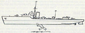
(iii) A typical destroyer.
22. These are dealt with in that order, the last two being discussed in less
detail than the first, except where major differences occur. The descriptions
should give the reader a basis on which to build up a knowledge of his own
particular ship.
23. This may be considered as the main type of larger cruiser in the Service.
In Plate1 is a picture showing the guns and the places in the ship from where
these guns are loaded, controlled, and fired.
Let us first consider the Main Armament. There are four Six-Inch Triple
Turrets; each turret is supplied with Shells and Cordite Charges from Shell
Rooms and Magazines situated below the turret and well protected by armour.
The shells and cordite charges are carried up to the Gunhouse, which contains
the guns, by endless chain hoists. Once inside the gunhouse, the shells are
placed inside the guns and rammed well into the gun by hand. Cordite charges
are then placed behind the shells and the breeches closed by hand.
When the guns have been loaded, they must be moved so as to point towards
the enemy ship or other target and also elevated so that the shells, which are affected
by gravity, will reach the enemy ship which may be a great distance away.
Note.-Later ships of this class have only three triple turrets, an extra twin A.A. mounting being fitted in lieu of X turret.
" 24. The Captain on the bridge decides which enemy ship is to be
engaged and, in Visual Fire (i.e. when the enemy can be seen) he moves a
sight known as the Captain's Sight, which indicates the hearing of the enemy
to the Director Control Tower. The Director Control Tower, as its name implies,
is the position in the ship from which the guns are directed, controlled, and fired. When the crew of the Director Control Tower receive an indication of the
enemy from the Captain's Sight, the tower is trained round until the target
can be seen. The bearing of the target thus ascertained is sent down to the
guns electrically, and they are then trained round until they are on the same
bearing as the Director Control Tower. This bearing is also sent by the Director
Control Tower to the Transmitting Station, the gunnery nerve centre of the
ship, which is under armour protection.
In blind fire (i.e. when the enemy cannot be seen but is detected by Radar
(see paragraph 351)) the movements of the enemy are plotted. A bearing of
the selected target is passed to the Transmitting Station, and it is then transmitted to the director and guns (see paragraph 297)."
6
25. By means of an instrument known as the Admiralty Fire Control Table in
the Transmitting Station the "Aim-off," or additional training movement required to hit the enemy, is calculated and sent to the guns, so that they are now
pointed in a slightly different direction from the Director Control Tower. The
Admiralty Fire Control Table also sends to the guns the movement in elevation
required by the range, and when the guns follow this movement they are elevated
the correct amount to make the shell reach the enemy. The range of the enemy
is measured by the Radar set in the Radar office and also by Optical Rangefinders in the Director Control Tower. Now that the guns are pointed and elevated
correctly, they are ready to be fired by the Director Layer, who is in the front
position of the Director Control Tower, looking through a telescope at the enemy.
The telescope is mounted on a Director Sight. Beside the Director Layer is the
Director Trainer, who trains the Director Control Tower on to the target and
keeps it trained on the target as the latter moves, thereby enabling the guns "to be
correctly trained. When the guns are ready to be fired, the fact is indicated to the
Transmitting Station by lamps, which are called Gun Ready Lamps. As soon
as all these are showing READY in the Transmitting Station a push is pressed
on the Admiralty Fire Control Table, which rings a gong in the Director Control
Tower. When this is heard by the Director Layer he presses his trigger as soon
as he is on the target, and all the guns are fired together by an electric current.
26. The Control Officer and his assistants, the Spotting Officer and the Rate
Officer, sit in the rear end of the Director Control Tower, watching the enemy
intently through binoculars. The Rate Officer passes down the enemy's course
and speed and any alterations of these. The Spotting Officer waits until the
splashes of the shells appear around the target, when he decides whether they are "over" the target, "short" of it or "straddling." All this information is passed
to the Transmitting Station, where it is set on the Admiralty Fire Control Table
and the next group of broadsides fired. Normally all the guns are fired together
as rapidly as is consistent with accuracy. It is essential to remember in this respect
that accuracy must come before speed. It is no good firing dozens of broadsides
very quickly if they do not hit; and they will not hit if they are not aimed
properly.
27. Before leaving the question of firing the main armament, it will be noticed
that there is another directing position in the after end of the ship, called the
After H.A./L.A. Director. This can be used for firing and controlling the main
armament, should the Director Control Tower get damaged, and it is also possible
to control and fire the foremost two turrets from the Director Control Tower and
the after two turrets from the After H.A./L.A. Director. This is done when it is
required to engage two enemy ships and in that case, a second instrument in the
Transmitting Station is used to pass training and elevation to the after guns.
This is called the Admiralty Fire Control Clock and it fulfils the same functions
as the Admiralty Fire Control Table but is a smaller and not quite such an
elaborate instrument.
The guns can also be fired from inside the turrets by local electrical circuits.
These are used only when the other positions have been damaged. The Turrets
are always controlled from some position in the ship remote from the guns, except
as a last resort, when the Turret Officer can control his own turret or a group of
turrets.
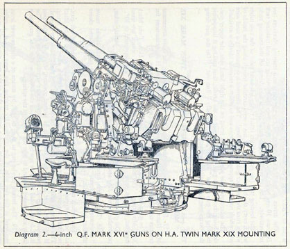
28. Now let us consider the Long Range Anti-Aircraft Armament. The
guns are Twin 4-inch guns and there are two pairs either side of the ship. They
are supplied with ammunition by hoists from magazines below the guns, under
armour protection.
Once again the guns are controlled and fired from Directors, known as H.A.
Directors, of which there are three. The two foremost directors are one each
side of the bridge and the after one is the combined H.A./L.A. Director.
7
The Directors are put on to the enemy aircraft by the Air Defence Officer,
after the target has been picked up by Radar or one of the Lookouts in the Air
Defence Position.
The Director is trained round and elevated, until the aircraft is picked up by the
Director Layer and Trainer in their telescopes. This movement goes electrically
to the H.A. Calculating Position, where the necessary "Aim off" is added, and
thence to the guns. The guns follow these movements and are, therefore, pointing
in the correct direction. 'The range of the aircraft is being taken by Radar and
by an optical Heightfinder in the H.A. Director and this information is transmitted to the H.A. Calculating Position, where an instrument called the High
Angle Control System Table, sends out to the guns, electrically, continual adjustments to elevation and training and the fuze to set on the nose fuzes of the high
explosive anti-aircraft shells. The High Angle Control System Table also rings
a fire buzzer at regular intervals, and while this is ringing in the H.A. Director,
the Director Layer presses his trigger and thus the guns are fired. The guns are
fired as fast as possible; but again it must be remembered that accuracy of pointer-following by the Gunlayer and Trainer and the accurate setting of fuzes is of more
importance than speed.
29. It will be noted from the Plate, that there are two H.A. Calculating
Positions and, normally, each H.A. Director controls the guns on its own side
through its own Calculating Position, but the After H.A. Director can control
either side through either H.A. Calculating Position.
The decision as to which H.A. Director is to control the H.A. guns rests with
the Air Defence Officer. He is responsible for directing all the anti-aircraft
armament in the ship.
30. At night the H.A. guns can be used to illuminate the enemy by firing
Star Shell to burst over the enemy ship, and so silhouette her against the glare
of the falling stars. The guns, in this case, are controlled and directed from the
Bridge and are fired by the gunlayers at the guns themselves.
31. The remaining part of the gunnery equipment of the ship is the Close-Range Anti-Aircraft Armament, consisting of Multiple Pom Poms which fire a
2-pounder High Explosive shell from four barrels and are controlled from Pom
Pom Directors near he guns, and also twin Oerlikon mountings which are
controlled at the mounting itself. Both these guns are power-operated and carry
the ammunition on the guns, being replenished throughout the action from nearby
magazines or lockers. Single hand-operated mountings are also carried.
Plate 2 shows a "Dido" class Cruiser with five 5.25 in. turrets;
all these ships have now had Q turret removed and replaced by a
Multiple Pom Pom.
32. This is a smaller cruiser than the previous one, the main difference being
that it carries only one type of long-range gun-the 5.25-in. Combined High
Angle and Low Angle Twin Turret. These ships mount four Turrets, two
being forward and two aft. They are fed with both High Angle High Explosive
Shell and Low Angle Semi-Armour-Piercing Shell and Cordite Charges in brass
cylinders, from Combined Magazines and Shell Rooms, one below each
turret and under armour protection. The shells and cordite are sent up to the
turret gunhouses by hydraulic hoists of the pusher type, that is to say, they are
pushed up by steel arms, which take under the base of the shells until they arrive
at the top of the hoists. On arrival the shell and cordite charge are placed in a
tray in the rear of the breech of the gun and they are then rammed into the gun
together by hydraulic power.
8
33. Let us consider Low Angle firing first of all. The guns are loaded with
Semi-Armour-Piercing Shell and Cordite and, as before, the Captain puts the
Director Control Tower, which is at the rear end of the bridge, on to the enemy
ship to be engaged, by means of the Captain's Sight. As the Director Control
Tower trains round, so the guns follow up. "Aim off" and elevation are
calculated in the Transmitting Station and sent to the guns, until they are
pointed towards the enemy and elevated so that the shells will travel the distance
between our ship and the enemy. The Transmitting Station contains an Admiralty
Fire Control Table, for Low Angle Fire, the same information being set 'on it as
before by the same control personnel in the Director Control Tower.
The guns can also be controlled and fired in Low Angle from the After
H.A./L.A. Director through the Admiralty Fire Control Table and each group
of guns can be controlled and fired from its own Director, i.e. the forward two
turrets from the Director Control Tower through the Admiralty Fire Control
Table, the after two turrets from the After H.A./L.A. Director through special
Low Angle Arrangements in the After High Angle Calculating Position. The
guns can also be fired locally from the turrets and controlled in groups from "B"
or "X" turret or from each turret separately.
34. In High Angle firing the H.A. Directors are put on to the enemy aircraft,
as before, by the Air Defence Officer in the Air Defence Position at the after end
of the bridge. It will be noticed, however, that in this class of ship the H.A.
Directors are mounted differently from those in a Six-inch "Mauritius" Class
Cruiser, in that there are only two of them, the forward H.A. Director being just
in the rear of the Director Control Tower. The H.A. Calculating Positions are
also arranged differently, the Main Transmitting Station holding the foremost
High Angle Control System Table, and the after High Angle Calculating Position
being amidships. The principle, however, of engaging the aircraft is the same, and
once again all the guns can be controlled and fired from either the forward or after
H.A. Director or each group of turrets can be controlled and fired from its own
Director.
For night action both "B" and "X" turrets are fitted for Star Shell Firing,
being controlled from the Star Shell Control Position in the after end of the bridge
and fired locally in the turret.
The Close Range Armament consists of 4-Barrel Multiple Pom Poms, which
are controlled from their own Directors, and also Single and Twin Oerlikon
Mountings.
35. The Destroyer (see Plate3), being considerably smaller than the Cruiser
and, therefore, with a very much smaller complement, has not such complicated
guns nor control arrangements, but the underlying principles are the same.
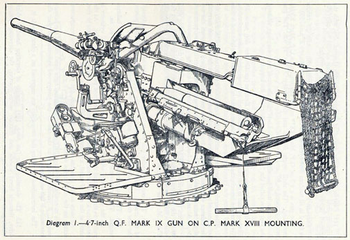
The guns are 4.7-in., capable of Low Angle and High Angle Fire, and
there are four of them, two being forward and two aft. These guns are entirely
hand worked, i.e., the Elevating, Training and Ramming are done by hand,
without hydraulic machinery. Underneath each pair of guns is a magazine
containing cordite charges in brass cases, with a Shell Room alongside each
magazine. These are transported to deck level by tackles, which are worked from
electric bollards, and from there they are carried to the guns and placed on loading
trays at the rear of the breeches. They are then rammed by hand into the guns,
the breech closing automatically behind the case of the charge.
Note. Later types of 4.7-in. guns have a spring-operated rammer.
36. In Low Angle firing the guns are loaded with semi-armour-piercing
shell and cordite charges and the enemy ship is indicated to the Director
9
Control Tower. In this case the Captain speaks down a voicepipe or telephone
to the Control Officer in the Director Control Tower, passing him the bearing and
description of the enemy. In Destroyers there are only two men in the Control
Group, seated in the rear of the Director Control Tower, namely the Control
Officer and Rate Officer. The Director Control Tower is trained round on to the
target by the Director Trainer, this movement being sent away to the guns
electrically; the guns follow by hand. The movement of training of the Director
Control Tower also goes to the Transmitting Station, which contains an
Admiralty Fire Control Clock. As before, the information regarding the enemy,
which is passed down by the Control and Rate Officers in the Director Control
Tower, is set on the Admiralty Fire Control Clock, which works out the "Aim
off" to be applied and the necessary elevation. This is also sent to the guns
electrically, where the movements are followed, so that the guns are now pointed in a
slightly different direction from the Director Control Tower and elevated according to the range of the enemy. The range is sent down to the Transmitting
Station from a Rangefinder, mounted in a Rangefinder Director at the rear of
the Director Control Tower. The range is also obtained by Radar, the Radar
Office being in the vicinity of the bridge and the Radar Aerials mounted on the
Rangefinder Director.
37. In High Angle Firing the same means are employed in indicating the enemy
aircraft from the bridge and the same movements of the Rangefinder Director,
both in elevation and training, go away electrically to the guns, which follow up
by hand. At the same time, the movement of the Rangefinder Director goes to
the Transmitting Station to an instrument called the Fuze Keeping Clock, which
calculates the "Aim off" and elevation to be applied to the guns, and the fuze
to be set on the High Explosive Shells which have been sent up from the magazines;
it also rings the Fire Buzzer at regular intervals which tells the Director Layer in
the Rangefinder Director the moment at which to fire the guns.
38. At night, "B" gun is used for firing Star Shell, orders being passed by voice
pipe from the bridge and the gun being fired locally. The necessary "Aim off"
in this case is estimated by the Star Shell Control Officer and applied to the gun,
which has initially been trained on to the target by the Director Control Tower.
39. The remaining part of the gunnery equipment is the Close Range Anti-Aircraft Armament, consisting of a 4-barrelled Pom Pom and a number of
Oerlikons. These are controlled and fired from the mounting.
40.
10
CHAPTER II.
THE SHIP'S COMPANY.
THE PART THE SHIP'S COMPANY PLAYS IN FIGHTING THE SHIP.
41. As will be seen from the previous chapter, the fighting efficiency of the
modern ship is built up from many instruments in various positions throughout
the ship, all doing their own special job, so that the combined ultimate effect
will be to sink the enemy. These instruments are as precise and as simple as is
possible, but they alone will not bring success in action.
Success, and in battle this means the life or death of the ship, depends on the
ship's company and upon you, as a member of the ship's company.
The ship's company is a team and they must practise as a team, in exactly the
same way as a good football team practises during the evening, although they may
be playing two matches a week. Having practised during the working-up period
of the ship at the beginning of the commission, they must go on practising, in the
same way as the Yorkshire Cricket Club go to the nets every evening, even though
they also may be playing two matches a week.
42. You must practise again, again and again. In the same way as a professional boxer goes through an intensive course of training before fighting his
adversary, so it is necessary for you, the gunnery men of the ship, to get yourselves into training for fighting the enemy. The only difference between you
and the professional footballer, cricketer, or boxer, is that whereas they are going
to enter a contest for which they will get prize money, you are going to fight an
enemy who, if you are not fully efficient, well trained, and in practice, will kill you.
This makes efficiency much more vital to you, and you can see how important are
those drills, which you do day after day and which go on when you think that you
know everything there is to know about your particular job.
Remember this; when you are detailed in the day's gunnery orders to close
up at your gun, your director, or your telephone, be there punctually. You
may meet the enemy at any time and in any weather. You may not have had
long to practise; see that you do not curtail that time by being adrift. Your own
life and the lives of your shipmates may depend on you.
45. The guns used in the Navy may be divided into three classes, heavy,
medium and light. In the first class come those above 8-in. calibre which constitute
the main power of attack of battleships and battle-cruisers. Into the second fall
guns from 8-in. to 4-in. intended essentially for use against other ships, and in
certain cases against aircraft as well. Those of the third class are mounted in
warships of every kind and include automatic guns for use against aircraft and
small fast surface craft.
All naval guns are loaded at the breech end. After the projectile and firing
charge have been inserted, the breech is closed by a breech block.
The charge used is cordite, a mixture of nitro-glycerine and gun-cotton
dissolved in acetone and stabilised by the addition of a small proportion of vaseline.
Cordite is prepared in the form of thick, cord-like threads, and is contained in a
pure silk bag. Silk is used because, when consumed in the explosion, it leaves no
residue.
HOW A GUN IS FIRED.
46. Behind the cordite charge a little tube containing a small quantity of
gunpowder is placed in the breech block to ignite the cordite which does not
take fire readily by itself. The gunpowder is electrically ignited by means of
a fine wire inserted in the tube. When the trigger of the firing pistol is pressed,
this wire glows white hot, thus igniting the powder, which in turn fires the
cordite.
CONSTRUCTION OF THE GUN BARREL.
47. A question often asked is why the barrels of long-range guns are always
so long themselves. To answer this question let us consider what happens when
a gun is fired. As the charge of cordite burns, a great amount of gas is produced
at a very high temperature. This gas, being confined in a small space by the
barrel of the gun, the breech-block, and the base of the shell, exerts an enormous
pressure on these-a pressure which is made much greater by its very high temperature. The barrel, which is being pushed outwards in all directions, cannot
move outwards without bursting; but it is made strong enough to stand the
initial pressure and does not burst. The shell, which is being pushed forward by
the gas at its base, moves forward up the barrel with ever-increasing speed, thereby
making more room for the gas and, to some extent, relieving the pressure. The
breech-block, which is being pushed backwards, is so strongly attached to the
barrel that though it moves back it takes the whole barrel with it. (This movement
is the recoil.)
If the charge used were high-explosive it would all burn, that is it would
turn into very hot gas, almost instantaneously, and the terrific pressure so produced would shatter both gun and shell. Cordite is used because a cordite charge
takes a very small but appreciable fraction of a second to burn (the larger the gun
the longer it takes) and it does not burst the gun because the shell begins to move
up the barrel as soon as the pressure on its base reaches a certain amount (and
this happens when only a small portion of the charge has turned into gas); as
12
it moves it makes more room for the rest of the gas; and by the time all the
cordite has burned the shell is perhaps three-quarters of the way along the barrel,
so that the total amount of gas produced is never all compressed in the original
small space. The pressure, in fact, is greatest just when the shell begins to move,
and this is why the gun barrel is made thickest at the breech, and tapered gradually
toward the muzzle.
To get full advantage of the driving power of the hot compressed gases, as
is clearly desirable for long-range firing, the barrel must be long enough to have
the moving shell still in it for as much time as the gases have enough pressure to
continue driving the shell faster and faster. The gases have this pressure for as
long as the cordite takes to burn and a little longer, and it is the distance the shell
travels in this very short interval of time that determines the best length for the
barrel.
48. Heavy naval guns are built up of tapered tubes shrunk on to each other.
Spiral grooves are cut on the inside of the inner tube. This rifling, as it is called,
causes the shell to spin during its passage up the gun (for reasons which will appear
later) and is naturally subjected to heavy wear. The design of the gun, however,
may allow the inner tube to be renewed when it becomes badly worn, and it is
not necessary to scrap the whole gun.
Many existing heavy guns are wound with wire in place of one of the shrunk
tubes. This wire assists the gun to resist the bursting effect of the gases inside it,
but is heavy and adds nothing to the strength of the gun as a beam. In consequence the gun tends to droop. Modern methods of heat treatment of tubes
have enabled wire to be dispensed with and it is not used for modern guns.
Modern types of medium calibre guns are made with single-tube barrels. This
has been made possible by improvements in the quality of gun steel and the
introduction of a special process in preparing the tube to withstand the internal
pressures to which it will be subsequently subjected. Besides the important fact
that this method is less costly, it has the advantage that there is no tendency for
the barrel to "whip" as the shell is discharged. Another great advantage is
that it makes it easier to change a worn barrel.
RIFLING.
49. The purpose of the rifling is to make the shell spin round on its axis in
the same way as a top spins on its axis; and as the spinning of a top keeps it upright,
so the spinning of the shell keeps it travelling nose first. Without this spinning
motion the shell would turn over and over as it travelled through the air, and would
go neither so far nor so accurately as it does when travelling nose first. The rear
end of the shell is surrounded by a copper driving band which is a very tight fit in
the bore. As the shell is propelled along the barrel the driving band is squeezed
into the grooves of the rifling causing the shell to acquire the spinning motion referred to in the previous paragraph.
PROBLEM OF RECOIL.
50. The speed at which a shell leaves a big gun is something like 2,750 feet
per second (nearly 2,000 miles per hour). The great force required to start off a
heavy shell from rest and give it such a speed in so short a distance, exerts a sudden
and powerful backward thrust, the shock of which would cause damage if the
gun was rigidly fixed to its mounting. It is therefore necessary to interpose a
buffer between the gun and its mounting to allow the gun to move to the rear
and bring it gradually to rest. This movement in recoil, as it is called, lessens the
shock of discharge and is provided for by the use of a hydraulic recoil absorber.
13
Attached to the gun is a piston with certain small openings, which works in a cylinder of liquid attached to the cradle, and when the gun is fired it attempts to
move backwards quickly, but the piston in the cylinder prevents its doing so.
The pressure set up in the cylinder by the restriction of the flow of liquid from
one side of the piston to the other, acts as a buffer to absorb the force of the recoil.
By storing some of the energy of recoil in springs or compressed air, power is
provided to run out the gun, i.e., to return it to its normal firing position.
BREECH MECHANISMS.
51. We have already seen that owing to the pressure set up in the chamber of
a gun when the charge is ignited, some means of sealing the rear end of the gun
must be provided; also some provision must be made for firing the charge. These
two functions are fulfilled by the breech mechanism, of which there are two very
distinct types, known as "Breech Loading" (B.L.) and "Quick Firing" (Q.F.).
(Q.F. guns are also loaded at the breech end.)
(i) B.L. Guns.
52. All guns of 6-in. calibre and above and certain smaller ones are B.L. guns,
the advantage being that the whole charge, which is made up in a silk bag, burns
away when fired, and there is nothing left in the chamber.
The B.L. mechanism consists principally of a screwed steel block, carried on
a bronze casting known as a "carrier," which is pivoted between hinge lugs on the
gun. The breech block screws into a similarly screwed bush inserted at the rear
of the gun. The threaded portions of the block and bush are stepped, so that
the threads may be fully engaged or disengaged by only a partial revolution of
the block.
When the gun has been loaded with a shell and cartridge, the carrier is swung
in towards the gun and the block, or breech screw as it is called, is revolved so
that its threads are in full engagement with those of the bush. To open the
breech, the screw is revolved to unlock the threads, and then the carrier is swung
clear of the gun, so that the latter may be re-loaded.
A small tube containing explosive material is placed in a chamber, called a
tube vent, formed in the breech mechanism in line with the axis of the gun.
By passing an electric current through the tube the explosive material is ignited,
and the flash thus produced causes the charge of cordite in the chamber of the
gun to ignite and fire the gun.
(ii) Q.F. Guns.
53. At Q.F. Guns, the charges are made up in brass cylinders. These charges
are protected more from wet and damp and to a great extent from flash, and are
therefore used at smaller guns in exposed positions; but they have the disadvantage
that the heavy brass cylinder has to be withdrawn from the gun after the round
has been fired.
Q.F. guns can be sub-divided again into three classes, Q.F., Semi-Automatic
(S.A.) and Automatic.
At Q.F. guns, the breech mechanisms have to be worked entirely by hand.
At S.A. guns, arrangements are made so that the breech will open, and the
empty brass cylinder will be ejected automatically after firing. Further, the
mere action of pushing in the next round causes the breech to close automatically.
At S.A. guns, then, the only action that is not automatic is the pushing in of the
next round.
14
At Automatic guns even the new round is loaded into the gun automatically,
and as long as the trigger is pressed the gun will go on firing and reloading itself.
The modern Q.F./S.A. breech mechanism consists principally of a rectangular
steel block, which is moved by a crank across a recess cut in the rear end of the
breech ring, which, in a Q.F. gun, is square in section. With the breech closed,
the face of the block bears against the base of the cartridge case, so that when
the gun fires, the pressure in the chamber, being unable to force the case to the
rear, expands the case so that it becomes a tight fit in the chamber and prevents
escape of gas to the rear.
The gun is fired by means of an electric needle, or a percussion striker, fitted
inside the block. With the breech closed, the needle passes through a small hole in
the face of the block and bears against the base of the cartridge case. An electric
current passed through the needle ignites the charge to fire the gun.
Where a percussion striker is fitted, the striker is held to the rear compressing
a spring. On pulling a trigger on the mounting, the striker is released, and the
spring forces it forward to strike a percussion cap in the base of the cartridge and
so fire the charge.
SUMMARY OF SAFETY ARRANGEMENTS.
54. The following is a list of all the safety requirements for which arrangements will be found at any gun.
(i) Breech must not open when gun is fired.
(ii) The electric contact must be broken before the breech commences to
open and vice versa.
(iii) It must be impossible to fire the gun until the breech is fully closed.
(iv) It must be impossible to fire the gun until the gun is fully run out.
In a B.L. Mechanism-
(v) The electric contact must be broken before the commencement of unmasking the vent.
(vi) It must be impossible to revolve the breech screw when the breech is
open.
55. The 6-in. Mark XXIII breech has been chosen as an example of a modern
B.L. mechanism. (See Plate5.)
The breech block of a B.L. gun can be considered for the moment to be a steel
plug screwed into the breech bush, which is screwed and shrunk into the "A"
tube of the gun with its front face butting against the rear of the inner "A"
tube, where a conical seating is formed. To make the breech gas-tight, a pad is
fitted in front of this plug and is shaped to bear against the conical seating. The
pad is called an obturator pad, and is made of shredded asbestos, impregnated
with rape-seed oil, enclosed in brass-wire gauze and subjected to a pressure
of about 15 tons/sq. in.
In front of this pad is placed a round piece of steel, the shape of a mushroom
carried on a stalk. The rear face of the head rests against the pad and the stalk
passes through a hole in both the pad and the breech block. This mushroom-shaped piece of steel is called the vent axial, though it is often referred to as the
"mushroom head."
When the charge is fired, the pressure set up in the chamber forces back the
vent axial, which in turn squeezes the pad against the front face of the breech
block, causing the pad to increase slightly in diameter and become a gas-tight
fit against the conical seating on the end of the inner "A" tube. When the shell
leaves the muzzle of the gun, the pressure on the "mushroom head" is released
15
and the pad, being elastic in nature, resumes its former shape, thereby pushing
the vent axial forward to its original position. Thus, although the rear end of
inner "A" tube is made gas-tight during the explosion of the charge, the pad
is normally just clear of its seating, so that no difficulty would be experienced
in opening the breech if the pad and "mushroom head" were to remain unaffected
by heat.
The high temperature set up in the chamber caused by the burning of the charge,
causes the "mushroom head," and hence the pad, to become hot. The amount
of heat is kept within reasonable limits by playing water on the "mushroom head" every time the breech is opened after the firing of a round. The heating of
the pad causes it to swell, with the result that it becomes rather a tight fit on its
seating. Some means must therefore be provided for unseating the pad during
the opening of the breech.
"56. Around the vent axial stalk are fitted a sleeve and a spring. These
are held in place by a nut which screws on to the rear end of the vent axial
stalk.
When the nut is screwed up, the spring is compressed, forcing the sleeve
hard against the front of the recess in the face of the breech block. With the
spring under compression, the sleeve and nut are forced away from each other,
thus drawing the mushroom head on to the obturator pad. In this way the
pad and its rings are held tightly in place at all times.
When the gun fires, the obturator pad, after being violently set back,
re-acts, and the spring absorbs this reaction.
The breech screw, in opening, moves slightly to the rear, forcing the
sleeve back with it but rotating around the vent axial stalk. Now if the pad
sticks to the inside of the chamber, the increased pressure on the spring will
unseat it."
Firing Arrangements.
57. In order to allow the charge to be fired, a hole is bored down the centre
of the vent axial stalk, a slightly tapered chamber being formed at the rear. In
this chamber is placed a tube, containing explosive material, which, when ignited,
will send a flash down the hole, on the rear of the charge in the chamber of the
gun. In order to fire the tube, a mechanism known as a lock is placed behind
it. The lock is fitted in a box slide, which is attached to the rear of the vent axial stalk
by means of interrupted collars. The vent axial nut is fitted with two lugs on its
rear face, and there are corresponding lugs on the front face of the box slide.
These lugs prevent the nut unscrewing and touching the front face of the box
slide. If the nut were allowed to do this, the action of unshipping the box slide
would tend to unscrew the nut farther to the rear against the box slide and a
complete jam would result.
The lock is fitted with an electrical contact which bears against the rear of
the firing tube, so that when the director firing pistol is pressed, current flows
through the lock to the tube, which is thus fired.
58. The requirements of a B.L. mechanism are:-
(i) That the breech screw shall only be free to rotate on the carrier when its
threads are in correct position in the gun to engage or disengage with the
threads in the breech bush.
(ii) That at all other times it shall be locked to the carrier in such a position
that it can be swung by the carrier freely into or out of the breech
16
opening of the gun, and that the act of locking the breech screw to the
carrier shall divert the power from revolving the breech screw to
swinging the carrier.
(iii) That when the breech screw is in the correct position in the gun to
engage the breech threads, the locking device, referred to at (ii) above,
shall be released in order to allow the breech screw to revolve.
59. This and the following paragraphs, together with Plate6, describe the
working of a Q.F./S.A. breech mechanism, but for a more complete representation
of any particular breech, reference should be made to the appropriate handbook.
The breech mechanism consists primarily of a breech block, rectangular in
shape, cut away at one end to facilitate loading, which slides across the rear end of
the gun in a slot called the breech mortice. The mortice is inclined to the face
of the breech so that the cartridge is forced home when the breech is shut.
60. The breech is operated by the actuating shaft which is vertical and
pivots in bushes built into the breech ring. The actuating shaft carries two cranks,
the lower one working the breech across the breech face, and the upper one turning
the actuating shaft when the breech is in semi-automatic.
The crank, which works the breech block, in its fully closed position is over
its dead centre so that the breech is locked. The further movement of the crank
beyond its dead centre permits the following safety arrangements to be provided:-
(i) The striker is withdrawn before the block is moved to open the breech.
(ii) The breech is fully closed before the striker can go forward.
61. The breech mechanism is operated by a breech mechanism lever,
carried on but free to move relative to the actuating shaft. Keyed to the actuating
shaft are a crank and rack pinion. Through the rack pinion and a bar carried
in the B.M. lever, the lever can be made rigid with the actuating shaft. This
is done in Q.F. to enable the crank to be rotated by movement of the B.M. lever.
Also carried in the B.M. lever are a rack and actuating spring. The rack is
geared to the rack pinion. Thus with the B.M. lever locked in the "housed"
position, movement of the actuating shaft will, through the rack pinion and rack
compress the actuating spring. This action takes place in S.A., a bell crank arm
attached to the actuating shaft being revolved as the gun runs out.
62. The Extractor is housed in the breech ring. It has toes on the outer end
which engage behind the rim of the cartridge case. The heels of the extractor
bear against inclined faces formed on the breech block. Initially, because of this
inclined face the extractors produce a powerful wedging action to commence
the extraction of the cartridge case, and then as they revolve about their axis,
a violent ejection of the cartridge case from the gun.
63. The breech is held open by the catches retaining breech block open.
On loading, the flange of the cartridge trips these catches; and in S.A., as soon
as the cartridge is home the breech is closed by the action of the spring in the
B.M. lever.
A small lever pivoted in the breech block called the catch retaining cartridge
is provided to retain the cartridge, because when the rammer is withdrawn quickly,
e.g., at high elevation, the action of the breech block is not sufficiently rapid to
hold the cartridge when the rammer is withdrawn.
17
64. The Breech Block Buffer consists of a block and a return spring, and
is housed in a pocket at the inner side of the breech ring. It has a threefold
purpose:-
(i) It limits the opening travel of the breech block.
(ii) It returns the breech block to the loading position in Q.F. action, thus
freeing the extractor, and then carries it on to the cartridge retaining
position on loading.
In S.A. action the actuating spring closes the breech and the buffer
plays no part except to assist at the commencement of closing.
(iii) It acts as a shock absorber when the breech is opened violently.
65. The Firing Mechanism is contained in the firing case which fits into the
breech block, where it is locked in the correct position by a spring hinged catch
lever. Although the electric firing gear is normally used, percussion firing gear is
fitted in most Q.F. breeches and is contained in the same unit.
The firing mechanism is operated by a series of retracting levers and crank
situated in the hollowed inner side of the breech block.
The firing circuit cable passes by way of the interceptor through a hole in the
breech block to the firing needle.
66. The Semi-Automatic Gear consists of a cam plate, secured to the beam
carrying the balance weight, which works against the operating cam on the
gun.
A change-over lever with two positions-S.A. and Q.F.-is provided.
When the lever is to Q.F. the actuating shaft roller of the breech passes clear
of the operating cam and no movement of the breech itself will take place. With
the lever to S.A. the actuating shaft roller runs along the inner edge of the operating
cam and thus rotates the actuating shaft and opens the breech as the gun runs
out.
Opening in S.A.
67. As the gun runs out the upper crank of the actuating shaft is rotated by the
operating cam and the breech is opened. During this movement the rack pinion
is also rotated, and operating the rack in the casing of the B.M. lever compresses
the actuating spring. The B.M. lever is secured to the gun by its plunger catch
whilst the breech is in S.A.
At the commencement of the crank rotation and until the crank pin passes
over the dead centre by an amount equal to the overlocking movement, no actual
displacement of the breech block occurs.
During this idle movement of the crank the firing needle is withdrawn within
the face of the breech block, and it is retained in the retracted position until the
crank reaches the same position when the breech is being shut.
As the breech block approaches the fully open position the curved inclined
face in the block comes into engagement with the heels of the extractor, and
rocking the extractor arm on the gun forcibly levers the cartridge case from the
chamber. At the end of this levering action the extractor rotates on its axis and
the final movement of the breech block rapidly ejects the case from the gun.
The final stopping of the breech block is brought about by the breech block
buffer, the spring of which allows a small over-travel of the breech block during
which the momentum of the block is absorbed before it can come up metal-to-metal. As the breech block is returned by the B.M. lever actuating spring the
block is arrested at the loading position by catches retaining breech block open.
18
On loading, the rim of the cartridge engages with the lips of the extractor
and with the catches, forcing them forward until they are disengaged from the
breech block thereby allowing the latter to close until the cartridge is retained and
the block is again arrested by the loading tray interlock bolt. When the tray is
moved back to the firing position the locking bolt is withdrawn and the breech
closes completely.
Opening in Q.F.
68. The S.A. cam is housed so that as the gun runs out, it is clear of the actuating
shaft roller and the mechanism is operated by the B.M. lever. When the handle
of the B.M. lever is grasped the lever is locked to the actuating shaft as described
above.
At the same time the lever retaining catch plunger in its socket in the breech
end is released thus freeing the B.M. lever. Movement of the B.M. lever will
then rotate the actuating shaft and open the breech.
CARE AND CLEANING.
Care of Bores of Guns.
69. The bore and chamber of a gun must be kept clean, and except when ready
for immediate use, oiled. To enable this to be done a special brush, called a
piasaba brush, is supplied for each type of gun in the ship. The act of cleaning
or oiling the gun with a piasaba brush is called sponging out.
Guns are sponged out and oiled:-
(i) Immediately after firing.
(ii) After bad weather or being at sea.
(iii) At least once a week in harbour.
(iv) Before and immediately after firing sub-calibre guns or aiming
rifles.
Sponging Out.
70. After firing, the gun is sponged out by passing a piasaba brush up and
down the entire length of the bore. To make certain that all the dirt is removed
from the grooves of the rifling, oakum is packed tightly round the bristles of the
brush.
When the bore is thoroughly clean it must be oiled. This is done by putting
clean oakum round the piasaba brush and soaking the oakum in light mineral oil,
and then passing the brush up and down the bore until there is a thin film of oil
over every surface in the bore.
Cleaning the Chamber.
71. The chamber is cleaned in a very similar manner to the bore, except
that the piasaba brush cannot be used, as it is not large enough. The combined
sponge and rammer supplied for the gun is very suitable for removing the dirt.
The oil can then be applied with a long handled paint brush or a cloth mop on a
long handle.
Cleaning Guns before Firing.
72. Before firing takes place the bore and chamber of the gun must be sponged
out until they are quite clean and free from oil. They are then left dry.
19
Care of Breech Mechanisms.
73.
(i) All working-that is, moving-parts must be cleaned and oiled first.
If any spare time remains it may be spent in polishing and burnishing
brightwork.
(ii) No brick dust, emery, or other gritty substance is to be used on any
working parts or inside the gun. These parts are to be cleaned with
oil only.
(iii) There are only two places for cleaning gear: one is when in use, and
the other is in the rag tank.
(iv) Never use any oil unless it has been especially provided by one of the
gunnery staff.
(v) When filling an oil hole it is advisable to clean the hole first with a piece
of wire. This will allow the oil to reach those parts for which it is
intended.
(vi) Always replace the lids or covers to lubricators. If a part of the mechanism
has been stripped down, make sure that all the keep screws, nuts,
split pins and keep plates are replaced when the gear is re-assembled.
(vii) If any gear seems stiff to work or assemble never hammer it with metal.
Look round to see if the cause of the stiffness can be found, and if
not report the matter to the senior rating of the gun's crew.
(viii) Always see that the breech threads are clear of dirt, and never force
the breech to close if it feels stiff. A burr may have occurred somewhere
and if it is on the seat of obturation the pad may be ruined by using
extra force.
(ix) Take great care of locks and box slides, and never let them be dropped.
(x) Never let a percussion lock be fired or allowed to snap unless a tube
or cartridge is in front of it, as otherwise the striker point may break
off. If a striker is found to be broken, do not rest until the broken
piece has been found, as otherwise it may cause a jam in some part
of the mechanism.
(xi) Never oil a lock. If it is dry or stiff report the fact to the senior member
of the gun's crew who will inform the gunnery office. An Ordnance
Artificer will be detailed to find out what is wrong.
(xii) Never disconnect an electric circuit without a direct order from a higher
gunnery rating.
85. Every gun mounting, whatever its size, is in essence a strongly-built
turntable, upon which is fitted a pair of brackets adapted to receive the trunnions
of the cradle and so carry the gun. The turntable enables the gun to be trained
round to any desired direction, and the trunnion pins and brackets form a pivot
about which it can be elevated or depressed as required.
The trunnions cannot be fixed to the gun itself. If they were, the mounting
and the ship's structure would have to be strong enough to stand the sudden
shock of recoil when the gun is fired; and as the gun is forced back with as much
energy as the shell is forced forward this would require very strong mountings
and very heavy ships even for small guns, and large-calibre guns would be out of
the question. The trunnions are therefore fixed to the cradle, and between the
gun and the cradle a buffer is interposed. By allowing the gun to move backward
and offering a strong resistance to this movement the buffer changes the sudden
shock of recoil into a comparatively long and much less violent push before it
reaches the fixed structure of the ship.
In lightly-built ships, such as destroyers, the shock has to be spread over a
longer interval than in larger ships, as the structure is less substantial. This is
done by allowing the gun to recoil further; in other words, by reducing the
resistance offered by the buffer or recoil cylinder.
This backward movement or recoil of the gun is provided for by mounting
the gun in a cradle (as mentioned above) in which it can slide to and fro when
necessary; and it is to this cradle that the trunnion pins are fitted and the elevating
gear attached.
86. In all smaller mountings the cradle consists of a tube in which the gun
slides and which carries the trunnion pins. The fixed portion of the recoil gear is
attached to the cradle and the moving parts are secured to the gun by attaching
them either to lugs formed on the breech ring or to the balance weight fitted round
the rear of the gun.
The latter method is employed in the 4-in. Twin Mounting where, owing to
the weight of the fixed ammunition used, there is no need for a loading tray. The
former method is generally employed on mountings fitted with loading trays,
where the tray and fittings provide a considerable part of the balance weight
necessary to balance the gun and cradle about the trunnions.
87. There are two types of mounting in use in the Service, the Pedestal
Mounting and the Central Pivot Mounting.
88. This type was used in older ships and for secondary armament guns of capital ships where guns are between decks. It is a comparatively low mounting, fitted with trunnion blocks so that guns can be run back between decks when required for examination purposes.
The base of the mounting is a large heavy casting, secured to the deck by a number of hold-down bolts. This casting is called a pedestal. The portion
21
which trains round is called the carriage, and consists of a "Y" bracket; the two arms hold the trunnion blocks and so take the weight of the gun and cradle. The lower part of the bracket is a large vertical pivot which fits into the centre of the pedestal. The weight of the carriage is taken at the bottom of the pivot which rests on a set of balls or rollers in a bearing. Two sets of vertical roller bearings in the pedestal keep the pivot central and thereby maintain training efforts of a reasonable standard.
The trunnion blocks fit into recesses in the arms of the "Y" bracket and are fitted with roller bearings to receive the trunnion pins. The gun is mounted in a cradle, and is prevented from turning during the passage of the shell up the barrel by its external keys engaging corresponding keyways in the cradle.
89. This type is used for all modern guns. Owing to its design which allows
for a deep opening between the carriage sides, it is possible with these mountings
to obtain a much greater elevation than with the pedestal type.
In the central pivot type of mounting the trunnions are carried at the top of two
steel plates which are cross-connected by a third plate in front; these three plates
are secured at the bottom to a flat, circular plate, on the underside of which is a
smooth ring which forms the upper roller path. The lower part is a flat, circular
base plate, secured to the deck by holding-down bolts, and with another smooth
ring on it which forms the lower roller path. Between the roller paths are
a number of cone-shaped rollers whose axis pins are secured to a light ring
inside the roller paths, so that the rollers are at all times kept in their correct
relative positions. As the gun and carriage train round, the upper roller path
pushes the rollers round over the lower path, and the roller ring to which the
axis pins are attached moves round at half the speed of the carriage.
In order to ensure that the two roller paths remain in the correct position
over each other, and that the carriage does not move sideways, a small pivot is
secured to the bottom of the carriage in its centre and works in a bearing in the
centre of the base plate. This pivot is called the central pivot.
Clips are fitted to prevent the mounting from jumping at the front and rear
when the gun is fired.
The Central Pivot.
90. The central pivot is secured to the revolving platform. It is hollow and
extends downward through the boss of the base plate. Electric cables, voicepipes, drain pipes, and, where required, pressure and exhaust pipes to the
mounting, pass through the central pivot. On the outside of the pivot is the inner
roller race, and between this and the outer roller race are the vertical rollers,
carried in a cage.
CRADLES.
91. In the older mountings, the gun is prevented from turning during the
passage of the shell up the bore by the engagement of its external keys with the
corresponding recesses in the cradle. In modern mountings either the lug on the
underside of the breech ring slides in guides attached to the rear of the cradle,
and thus prevents the gun from turning or (in mountings where the balance weight
recoils with the gun) flats formed on the recuperator cylinder body engage with
metal guide strips on the balance weight.
Cradles are fitted internally with brass bearing rings, upon which the gun rests,
and slides, when recoiling and running out, to reduce the friction between gun
and cradle.
On the underside of each cradle is fitted a recoil cylinder.
22
TRUNNIONS.
92. The gun trunnion pin is a steel pin, screwed and shrunk into the cradle,
and further secured by a locking screw.
93. These are generally central pivot mountings. To permit easy loading
at high angles of elevation the trunnions are fitted as near to the breech of the
gun as possible, a balance weight being fitted to the cradle or rear end of the
gun to balance the gun.
The most modern mountings carry guns which are used both as H.A. and
L.A. Armaments, and are actually C.P. mountings, which allow high angles of
elevation.
The modern tendency is to mount guns in pairs, the cradles being either in
one piece or bolted together. The number of guns may thus be doubled without
requiring very much extra space.
RECOIL ARRANGEMENTS.
94. Types of recoil arrangements can be divided into the old and new types, and the former will be dealt with first.
The recoil cylinder is a steel forging secured to the underside of the cradle. The rear end of the cylinder is screwed for the reception of the cylinder closing plug. The front end of the cylinder is bored to receive a controlling plunger, which is secured by a nut, outside the cylinder. The plunger is hollow and a hole at the front end is in communication with the inside of the plunger and the front end of the cylinder. The passage of liquid from inside the plunger to the recoil cylinder is restricted by an adjusting spigot which is screwed into the front end of the plunger. The spigot has a flat filed on it, the size of which can be adjusted to regulate the speed of run-out of the gun.
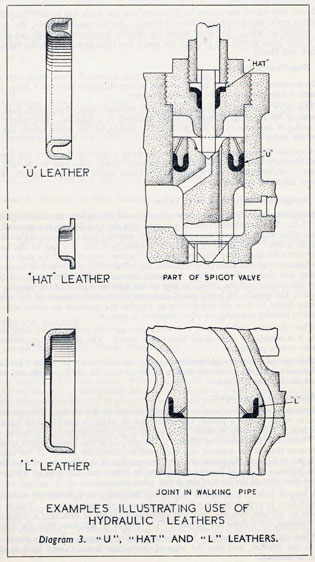
When the gun is in the firing position the control plunger is housed inside the hollow front part of the piston rod, the solid rear end of which passes through the lug formed on the underside of the breech ring of the gun and is secured to the lug by a nut on either side. The piston rod is not a tight fit in the recess of the lug, and thus allows self-alignment of the rod with the cylinder should any wear take place in the cradle. It is important therefore that the nuts on the piston rod should not be tightened right up. The space at the rear end of the cylinder between the cylinder and the piston rod is sealed by means of the cylinder closing plug. This contains a stuffing-box with a "Hat" leather and cotton packing secured by a gland.
95. A channel leading from the rear face of the piston through the piston head to the hollow space in the piston rod, is fitted with a non-return ball-valve to allow liquid to pass from the cylinder to the hollow piston rod through the piston head, but not to return that way. A port is cut in the piston head at its lowest point to allow liquid to flow past as the piston head moves with the gun; and the rate of this flow, especially during recoil, is controlled by the valve key. The valve key is secured to the bottom of the recoil cylinder. This key reduces the effective area of the port in the piston head for the passage of liquid to the front end of the cylinder; and its height is so varied (in general it gets higher towards
the rear) that the resistance which the liquid offers to the piston and the resulting strain on the mounting and the ship's structure are constant throughout recoil.
23
The recoil cylinder is completely filled with a mixture of 50 per cent. distilled water and 50 per cent. glycerine. A replenishing tank is secured to the cradle.
The purpose of this tank is to supply liquid to fill the space vacated by the piston rod during recoil, and to replenish the cylinder automatically if any leakage of liquid occurs through the gland. A hole in the side of the tank, provided for cleaning it out is closed by a screwed plug and leather washer. At the top of the tank are filling and air holes, which are also closed by screwed plugs and leather washers.
96. When the gun recoils, the piston rod is pulled to the rear and liquid from the rear end of the cylinder passes to the front and through the gap between the valve key and the port in the piston head. Liquid also forces the ball valve off its seating to fill up the space in the hollow piston rod vacated by the control plunger. As the gun moves to the rear the effective size of the port opening in the piston head is gradually reduced by the valve key until it is almost completely closed. This increasing restriction of the flow of liquid past the piston gradually increases the resistance which the liquid offers to the piston and so brings the gun gently to rest.
When the gun is in the fully recoiled position, the front end of the cylinder, the hollow piston rod and control plunger are completely filled with liquid. The gun is forced forward into the firing position by means of run-out springs, and the liquid at the front end of the cylinder passes through the gradually opening piston-head port, to the rear end as the piston moves forward.
97. The liquid in the hollow piston rod, unable to flow back into the cylinder through the non-return ball-valve as the piston moves forward, is forced through the hole in the control plunger and past the adjusting spigot into the front end of the cylinder. The size of the available outlet for the liquid in the hollow piston rod is thus determined by the flat on the adjusting spigot; and this constriction, by setting up pressure in the liquid in the piston rod, controls the speed of run-out. The very last fraction of run-out is further slowed down by the valve-key rising steeply at its front end and almost closing the piston-head port, so that the flow of liquid past the piston is almost stopped, causing the gun to come gently to rest in the firing position.
If the run-out is too slow, it can be speeded up by increasing the size of the flat on the adjusting spigot, but if run-out is too fast, a new spigot with a smaller flat must be fitted.
The more recent of the older mountings are fitted with a needle valve in place of the spigot. This may be screwed towards or away from its seating to adjust the speed of run-out.
98. The new type of recoil arrangements are fitted to all modern mountings,
large and small, and though details differ the general principles are identical.
The recoil cylinder is carried in a hollow projection on the underside of
the cradle. It is prevented from turning by a flat formed on the front end,
which engages with a facing in the cradle, and is secured by a nut at the rear end.
It is fitted with a drain plug at the front, and an air escape plug at the rear
end.
Within the cylinder is a partly hollow piston rod, the piston head of which
is fitted with a phosphor bronze piston ring and has a number of ports cut in its
rear face and a control or throttling bush screwed into its front end. Grooves
which are tapered towards the rear are cut in the inside surface of the piston rod.
24
The solid rear end of the piston rod is secured to the breech ring of the gun,
a clearance between the securing nuts and the lug on the breech ring being
provided so that the rod is free in the lug. In the hollow of the piston rod fits a
tapered control plunger which is secured at its front end by the cylinder closing
plug. This plug is fitted with an air escape hole to prevent an air lock when
screwing in the plug. This hole is closed by a bolt.
Fitted over the rear end of the control plunger is a sliding sleeve non-return
valve, whose seating is a shoulder formed on the control plunger.
Briefly stated the throttling bush in conjunction with the tapered control
plunger controls the speed of recoil, and the grooves cut in the interior of the
hollow piston rod control the speed of run-out.
99. As the gun recoils the piston is pulled to the rear. The liquid in rear of
the piston passes through piston head ports, and thence, between the throttling
bush and the tapered control plunger, into the front part of the cylinder. The
control plunger is tapered to obtain an approximately uniform force of recoil.
Some of the liquid also passes to the rear between the control plunger and the
interior of the piston rod and, pushing the sleeve-valve off its seating, passes through
the ports in the valve and fills up the increasing space inside the hollow piston rod.
The taper of the control plunger gradually reduces the space between it and the
throttling bush bringing the gun gently to rest. If the gun reaches its maximum
working recoil, the stepped parallel portion of the control plunger just enters
the throttling bush and almost completely cuts off the flow of the liquid.
100. As soon as the gun has been brought to rest, it is forced forward by
the action of compressed air in the recuperator in a manner to be described later.
In the recoil cylinder, the piston moves forward over the control plunger, and at
the first movement to the front, the liquid in the rear of the space in the hollow
piston rod forces the sleeve valve on to its seating.
The liquid trapped in the hollow piston rod can now only escape past the
sleeve valve through the grooves cut along the inside of the piston rod. A pressure
is thus built up in the hollow piston rod and the tapered grooves by varying the
flow of this pressure, control the speed of run-out. As the front face of the breech
ring meets the bearing face on the cradle the tapered grooves then surrounding
the sleeve valve are of minimum depth, and so the gun is brought gently to rest.
A comparison between the old and new types of recoil arrangements will
show that the original principles are still applied, though in a different form;
the valve key of varying height and the part in the piston head have been replaced
by the tapered control plunger and throttling bush; the ball-valve has been
superseded by the sleeve-valve, and the adjustable spigot by the tapered grooves
on the inside of the hollow part of the piston rod. But the adjustable spigot is so
useful in providing a means of adjusting the speed of run out that, though dropped
for a time, it is being incorporated in the most modern mountings.
101. Run-out springs are fitted to older mountings and to later mountings
for which compressed air is not available, to keep the gun out in the firing position
and to return the gun to the firing position after the force of recoil has been
absorbed. It is obvious that the springs also absorb a certain amount of the force
of recoil.
A hollow cylindrical spring case is fitted to the top of the cradle. Inside
the case are three spiral springs with a rod passing through them. At the front
25
end of this rod is attached the fixed plate, which bears against the front end of
the foremost spring; and at the rear end of the third spring, inside the spring
case, is the compression plate. The spring rod is hollow and the rear end is
screwed on its inner surface to receive a screwed bush. The breech rod is passed
through the breech lug and the rear end of the spring case, through the compression plate and screwed into this bush. A flanged nut on the breech rod
engages with the compression plate, and is turned to screw the rod into the bush.
By screwing the breech rod into the bush on the spring rod, the fixed plate
on the front end of the latter is drawn to the rear, and the springs are thereby
compressed between the fixed plate and the compression plate. When sufficient
initial compression has thus been applied and the springs are entirely inside the
spring case, the nut on the screwed rear end of the breech rod is screwed up until
the flanged nut on the breech rod is drawn back clear of the compression plate.
This action transfers the forward pressure of the springs from the rear side of the
compression plate to the breech lug and so enables the springs to hold the gun
in the run-out position and to return it to that position after recoil.
102. All modern mountings are fitted with a recuperator to run the gun out
into the firing position and hold it there. The arrangement of fittings differs
according to the mounting to which they are fitted.
The recuperator cylinder is secured to the top part of the balance weight
by a nut on a screwed projection on its rear end. It is prevented from turning by
a flat formed on the front end which engages with a face on the top beam.
The recuperator ram is secured by a nut to a lug attached to the breech
ring of the gun and enters the cylinder through a gland.
The recuperator is filled with air at a pressure of about 600 lbs. per sq. in.,
through a spigot valve situated at the rear end of the intensifier, and is kept airtight by packing and a double set of "U" leathers supported by brass spring
rings. An inlet for liquid from an intensifier is led into the space between the pair
of leathers. An air release plug is also fitted to this space to enable any air present
to be released from the liquid system.
An air connection for the intensifier is taken from the rear end of the
recuperator; this connection also serves the purpose of charging the recuperator;
a drain valve is fitted at the rear end.
As the gun recoils, the recuperator ram is forced into the cylinder, causing
the air pressure to rise, until at the end of recoil a pressure some 70 per cent higher
than normal is reached. This further compression of the air absorbs about
25 per cent of the energy of recoil of the gun.
As soon as the gun has been brought to rest, the pressure in the recuperator,
acting against the forward end of the hollow ram, forces the gun out into the
firing position.
103. The intensifier is bolted to the outer side of the balance weight and
consists of a cylinder in which travel a piston and rod. A pointer attached to the
tail of the piston rod indicates whether the intensifier is full or empty.
A pipe transmits the recuperator pressure to the rear end of the intensifier.
The front end of the intensifier cylinder is full of low temperature grease No. 0,
and is connected by a pipe to the inside of the "U" leathers of the recuperator
gland.
The effective area on the rear face of the piston is greater than that of the
other side by the cross-section area of the rod, and the grease is consequently
26
forced into the recuperator gland at a higher pressure than that of the air in the
recuperator thus keeping the "U" leathers tight. As the air pressure in the
recuperator rises during recoil of the gun, so does the intensifier correspondingly
increase the pressure of the grease in the ratio of the effective areas of the two
sides of the piston head, so that whatever the air pressure may be in the recuperator
at a given moment the grease pressure must always be considerably higher.
104. A wheel or a pair of handles, worked by the gunlayer, is fitted at the
left side of the mounting for elevating and depressing the gun. Shafts and gear
wheels transmit the movement of the elevating wheel to a pinion which engages
the teeth of an elevating arc bolted to the underside of the cradle.
The shock of the gun on firing due to the movement of the centre of gravity
towards the rear end of the cradle, is transmitted by the pinion to the elevating
gear, which must therefore contain a worm and worm-wheel to prevent the gear
moving when the gun recoils.
The shock thus transmitted to the elevating gear is prevented from causing
damage by making the gear frictional. The same safety measure prevents damage
when the gun is elevated or depressed on to its stops in a violent manner.
105. The elevating handles drive through shafting and bevel wheels to a
worm. The worm meshes with a worm wheel which is on but not keyed to the
elevating pinion shaft. The worm wheel is hollow and contains alternate steel
and gun metal friction discs which are keyed, the one kind to the wormwheel
and the other kind to the shaft. These discs are compressed by Belleville spring
washers and a nut, and thus a frictional drive from the wormwheel to the shaft is
obtained. The elevating pinion is keyed to the elevating pinion shaft, which is
hollow to allow the drive to the elevation receiver to pass through it. This drive is
from split pinions working off the elevating arc.
Elevating and Depression Limit Stops.
106. Limit stops are fitted on top of the elevating pinion shaft bearings on
either side of the elevating pinion and take against steel plates bolted to the ends
of the elevating arc when the gun reaches the limits of elevation and depression.
Limit stops usually take the form of oil buffers, and have a two-fold purpose.
Firstly, they prevent the gun being elevated or depressed beyond the limits imposed
and secondly they apply these checks in a relatively gentle manner.
The mechanical details of buffer stops may differ in various types of mountings,
but the essential principles are always the same.
The buffer stop, which is placed in the path of some protruding portion of the
mounting consists of a cylinder containing a piston with its rod protruding. One
or more springs are fitted inside the cylinder, to keep the piston in its normal
position, i.e., make the rod protrude when it is not in contact with the other part
of the mounting. The cylinder is filled with General Service mineral oil. The
action upon the protruding portion coming into contact with the piston rod is to
drive it into the cylinder. The piston head, the diameter of which is only very
slightly less than that of the cylinder, tends to compress the liquid. Liquid,
however, cannot be compressed and it escapes past the side of the piston head until
the limit of travel is reached and the gun is brought to rest without undue shock.
Depression Control.
107. It is possible to depress the gun about five to ten degrees below the horizontal. This would entail a risk of the gun shooting into the deck or fittings mounted
27
on the deck when it is trained on certain bearings. To avoid this, a cam rail is
fitted to the deck close round the bottom of the mounting. On the plate runs a
roller which works a system of rods attached to the mounting, with a bell crank
lever at the top whose upper leg is under the gun. As the gun depresses, it is
stopped by its underside resting on the upper leg of the bell crank lever. On
dangerous bearings the cam plate is higher and when the mounting is trained on
such a bearing the roller lifts and raises the end of the bell crank lever thus preventing the gun being depressed too far. On the other hand, if the gun is at maximum
depression on a safe bearing and is trained towards a dangerous bearing the roller
will lift until it touches the gun, when the mounting will be prevented from being
trained further.
108. A wheel, or a pair of handles, operated by the trainer, is fitted to the
right side of the mounting. The drive passes through a two-speed gear box
and is connected by bevel gearing to a worm shaft. A muff coupling connects
the two parts of the vertical shaft.
The worm is keyed to its shaft and meshes with the worm-wheel. The
end thrust of the worm is taken on ball bearings, and a screwed bush at one end
can be adjusted to take up end play. The arrangement of friction discs is the
same as in the elevating gear described in para. 105, the vertical training shaft
passing through the worm-wheel. At the lower end of the shaft are two training
pinions, the two together usually being referred to as a split pinion, engaging
the teeth of the training rack, which is secured to the inside of the lower roller
path. The upper pinion is keyed with vertical keys, and is held in place by a
screwed collar.
The lower pinion is mounted on inclined keys and is held up against the upper
pinion by a flange on an internal shaft which passes through the hollow vertical
training shaft. The upper end of the internal shaft is screwed into the training
shaft, and adjustment to take up backlash may be made by screwing up the internal
shaft, which will raise the lower pinion, thus giving it a slight rotation, which
has the effect of widening the teeth engaging the training rack. The adjustment
is provided in this manner because a bevel attached to the top of the training shaft
transmits the drive to the director training receiver.
A collar on the training shaft forms a bearing for the worm-wheel, and the
weight of the shaft and worm-wheel is taken by a set of ball bearings. Two
vertical sets of roller bearings form the main bearing of the shaft in the casing.
In later mountings, the training pinion is one solid pinion keyed to the training
shaft, while the drive to the director training receiver is transmitted by a separate
pair of training pinions engaging the training rack. The details of the split pinion
adjustment are not shown in Plate13.
Training Stops.
(i) Housing Stop.
109. A hinged housing stop pawl is fitted at a convenient position on the carriage
and can be raised and lowered by a handle, which is then pinned in the required
position. The pawl engages with a fixed bracket on the base plate.
In some mountings the stop consists of a vertical-spring-loaded bolt fitted to
the turntable, which engages a recess in the base plate. The bolt may be pinned
in or out of engagement.
(ii) Training Stops.
Stops are fitted to mountings to prevent them being trained in a direction
that would endanger the structure of the ship if the gun were fired. There are
two kinds of stops, called permanent and semi-permanent stops. Permanent
28
stops are rigid and prevent any further movement of the mounting past a certain
point. Semi-permanent stops prevent the gun being trained on a dangerous
bearing, but the stop, when reached, can be lifted and the mounting trained further,
either for stowage, or to safe bearings beyond the dangerous arc.
The toe of the housing stop in each case comes into contact with a stop fixed
to the baseplate. Where the stop is a semi-permanent one, the elongated hole
in the housing stop, into which the locking bolt fits, is large enough to allow
this stop to be lifted sufficiently to clear the fixed stop on the base plate. Buffer
stops similar to those described in para. 106 are fitted to come into play just before
the fixed stop is reached, in order to prevent sudden shock.
110. Two long hollow tubes, which fit into lugs on the underside of the
cradle and project to the rear, carry the balance weight across their rear ends.
The loading tray is supported on this structure.
By means of a palm lever and handgrips the tray can be swung into line
with the gun for loading, or back clear of the path of the gun when it recoils.
A spring locking bolt, operated by the palm lever, locks the tray in either position.
Rounds are rammed into the gun by a hand-operated rammer or in the latest type
of mountings by
a spring-operated rammer.
An interlock is fitted to prevent the tray from being in rear of the gun when the
latter is in a position to fire, i.e., when the breech is closed. As the tray is pushed
over in line with the gun for loading, it forces a bar into contact with a cam at the
lower end of the breech actuating shaft. When a round is loaded into the gun,
the actuating spring closes the breech sufficiently for the block to retain the round,
when a projection on the actuating shaft cam comes into contact with the interlock
bar and prevents the breech from closing further. The last movement of the tray
on being swung clear withdraws the interlock bar, and the breech is closed by the
actuating spring.
. . . . depends upon you . . . (para 41)
29
THE 4.7-in. Q.E. MARK IX** GUN ON THE C.P. MARK XVIII
MOUNTING.
111. Chapter III and the preceding paragraphs in this chapter, deal with the
various parts of typical hand worked guns. These points should be carefully
studied before considering the gun and mounting as a whole.
Diagram 1 shows a destroyer's gun. This type of gun, with certain differences
is fitted in all modern destroyers up to the "W" class (see Chapter I, para. 35).
The gun is a 4.7-in. Q.F. Mark IX** and is mounted on a C.P. Mark XVIII
mounting. The shell weighs 50 lbs. and the cartridge 30 lbs. 5 1/2 ozs. The gun
can be elevated to 40° and depressed to 10°.
The gun itself (see Chapter III, para. 47) is built up of three forgings, namely,
the gun tube called the "A" tube, the jacket, and the breech ring.
112. The breech mechanism is of the Q.F. type (see Chapter III, paras. 53,
59 et seq.) and is provided with combined electric and percussion firing mechanism.
To open the breech, the breech mechanism lever is moved to the right and is then
housed when the breech is open.
The breech can be put to either SEMI-AUTOMATIC or QUICK FIRING
by means of a lever held in a bracket bolted and secured to the top beam carrying
the balance weight. Acting in conjunction with the cam is a roller on the top
of the actuating shaft. The change-over lever for the cam has two positions,
i.e., S.A. and Q.F., and is held in either position by a spring plunger.
When the lever is at SEMI-AUTOMATIC, the roller on the actuating shaft
strikes the operating surface of the cam as the gun runs out after recoil, and the
roller is forced outwards, thus rotating the actuating shaft and opening the breech.
The B.M. lever is left in the "housed" position.
113. The recoil cylinder (see paras. 98 and 99) is carried on the underside
of the cradle. Inside the recoil cylinder is the hollow piston rod and piston,
the rear end of the piston rod being secured to the breech ring of the gun.
114. The recuperator (see para. 102) is fitted on the top part of the balance
weight. The recuperator is filled with air at a pressure of 550 lb. per sq. in.
As the gun recoils after firing, the recoil piston inside the recoil cylinder is
pulled to the rear, and the liquid passes to the front part of the cylinder. At the
same time a ram is forced into the recuperator cylinder causing the pressure to rise,
until, at the end of recoil, a pressure of 1,000 lb. per sq. in. is reached.
As soon as the gun has been brought to rest, the pressure in the recuperator
acting on the ram begins to force the gun out.
The intensifier (see para. 103) is bolted to the top right hand side of the balance
weight. A pointer attached to the tail of the piston rod indicates whether the
intensifier is full or empty.
The instructions for filling the intensifier are engraved on a plate beside it.
115. The elevating gear (see para. 104) consists of elevating handles which
drive, through bevel wheels and friction worm-gearing, the elevating pinion
which gears to the elevating arc, and elevates the gun.
A safety stop is fitted to prevent the sight being depressed into a position
where the deflection dial would foul the elevating handles.
Elevation and Depression Stops and Depression Control Gear are also fitted.
30
31
116. The training gear consists of training handles driving through a two-speed gear box, bevel wheels, a frictional worm-gear, and a pinion which engages
the training rack.
The two-speed gear box has a clutch which can be put to FAST or SLOW.
One turn of the training handles equals approximately 4 degrees when the clutch
is put to FAST, and 2 degrees when put to SLOW.
The drives to the black pointers on the elevation and training receivers (see
Diagram 10 and paras. 276 and 279) come from the elevating arc and training rack
respectively. The tilt corrector (see para. 265) is also driven off the training rack.
The loading tray (see para. 110) is fitted to the left hand tube of the two tubes
which carry the balance weight. It has a semi-circular trough along the inside of
which runs the rammer guided by rollers. The rammer is operated by a steel wire
rope which runs over appropriate sheaves and to which a rammer handle is attached.
The interceptor (see para. 281) is fitted on the right hand side, the upper portion being fixed to the gun, and the lower to the cradle, thus making it impossible
to bring the gun to the "Ready" until it is fully "Run out." On the gun firing
the interceptor automatically opens.
THE 4-in. Q.F. MARK XVI* GUNS ON THE H.A. TWIN MARK XIX
MOUNTING.
117. Diagram 2 illustrates the 4-in. Twin H.A. Mounting, the main armament
of "Hunt" class destroyers and sloops, and the standard H.A. armament for
cruisers not equipped with H.A./L.A. guns (see Chapter I, para. 28).
The guns are 4-in. Q.F. Mark XVI* and are mounted on an H.A. Twin Mark
XIX Mounting. The total weight of the shell and cartridge, which are fixed
together, is 63 lbs. 8ozs. The guns can be elevated to 80° and depressed to 10°.
The gun itself is of all steel construction. It consists of a "loose" barrel, jacket,
removable breech ring and sealing collar (see Chapter III, para. 48).
118. The breech mechanism is so arranged that the breech blocks move
"downward" to open. This arrangement allows the guns to be placed closer
together in the cradle.
The breech mechanism lever is fitted on the left hand side of the left gun,
and on the opposite side of the right gun. As the breech block has to be lifted
vertically, a very strong spring is required to close the breech when in S.A. firing.
This spring is fully compressed when the block is open and the B.M. lever housed.
If the B.M. lever is then unlocked from its housed position, it will fly to the open
position with great violence, and it will severely injure anyone in its path. The
B.M. lever should therefore not be released until the breech worker has grasped it
firmly and pressed forward to take the thrust of the spring.
119. The breech can be put to S.A. or Q.F. by means of a change-over lever
mounted at the rear side of the cradle. By moving this lever to S.A. a roller
attached to the cradle is put into such a position that as the gun runs out it comes
into contact with a cam which is attached to the gun, and this operates the breech
mechanism.
The guns are normally fired electrically from the H.A. director, but they can
be fired locally by means of the gunlayer's trigger, and, if the electric circuit fails,
they can be fired by percussion, by means of palm-operated firing levers, by the
breech worker.
The guns are mounted in a common cradle and therefore, elevate together,
but each gun is provided with its own recoil and run-out arrangements.
32
33
The recoil cylinder is secured to the underside of the gun and recoils with the
gun. The recoil piston rod is secured to the cradle and does not move, but the
control plunger inside the piston rod also moves with the gun.
As the recoil cylinder travels to the rear when the gun is fired, liquid is forced
through ports in the piston head. The energy of the recoil of the gun is absorbed
mainly in the forcing of the liquid through these ports, but also partly by the
compression of the air in the recuperator cylinder.
120. The recuperator cylinder is secured to the cradle on top of the gun,
and the recuperator ram, which moves inside the recuperator cylinder, is secured
by the rods to the balance weight of the gun.
The recuperator is charged with air through the intensifier. An instruction
plate for charging the recuperator being fitted to the mounting.
The intensifier (see para. 103) is mounted on the cradle and is arranged with an
air-charging connection, and a liquid-charging adaptor. An indicator at the rear
of the intensifier shows whether the intensifier is full or empty.
The elevating gear is operated from the left hand side of the mounting by
means of two cranked handles. One complete turn of the handles elevates the
guns 3 degrees. The drive from the handles goes to a pair of bevel pinions, and
thence through a worm, worm-wheel and friction discs to the elevating pinion,
which engages in the elevating arc. The latter is on the centre line between
the two guns.
Safety firing gear is fitted and is designed so that the interceptors are opened
and cannot be closed between the limits of 20' elevation and 10° depression when
the mounting is trained into a danger zone. The gear is operated by a vertical
cam rail secured to the deck.
121. The training gear is operated from the right hand side of the mounting
by means of two cranked handles. The forward movement of the handles trains
the mounting to the right. One complete turn trains the mounting 4 degrees.
The drive from the handles passes through bevel wheels in two gear boxes to a
worm shaft, through a worm, worm-wheel and friction gear to the training pinion
at the front of the mounting, and so to the training rack.
Mechanical fuze-setting machines, for setting the time fuze on the nose of the
H.A. shells, are carried on brackets at the rear edge of the gunlayer's and trainer's
platforms.
MAINTENANCE OF MOUNTINGS.
Maintenance.
122. Maintenance is the keeping of apparatus in efficient working order by
means of careful treatment and by examinations, tests, repairs, preservation
(lubrication, scraping, painting), cleanliness and general tidiness.
Careful Treatment.
Much maintenance work can be saved by care-i.e., by knowledge, forethought
and common sense.
(i) Most breakdowns, involving heavy work and much delay, are due to
ignorance of gear, rough handling, bad drill or failure to detect and
remedy trifling defects or omissions.
(ii) Damage by salt water or by rain can be prevented by care in covering
guns, closing water excluders, sighting ports, ventilators, etc., and by
drying up water before rust forms.
34
(iii) The damage to paintwork and the general dirtiness caused by firing,
drills and ordnance work, can be largely avoided by care and cleanliness.
Ordnance Staff.
123. The Engineer Officer for Ordnance Duties, the Warrant Ordnance Officer
or Chief O.A. is responsible to the Gunnery Officer for all ordnance work and
maintenance of all gun mountings. He arranges the work of the ordnance staff
in accordance with the orders of the Gunnery Officer.
Defects.
124. All defects must be promptly reported to the O.O.Q. A defect book is
kept in the Gunnery Office in which all defects should be entered, whatever
department they concern.
Periodical Examinations.
125. All gun mounting machinery has to be stripped and examined at intervals
ordered by the regulations, whether or not it appears to be in good order, so
that wear and corrosion may be found and remedied before their effects become
serious.
Sweepers.
126. Sweepers are responsible for the cleanliness and tidiness of the quarters,
and particularly for the cleanliness and efficiency of the working parts of the guns
and machinery. They should prevent any irregularity in the quarters, such as
smoking or the hanging up and stowage of clothing.
They should help the O.A. of the quarters when he requires them, and in ships
where the gunnery orders state that they should assist with the lubrication,
that work must have the first call on their time.
Lubrication.
127. The ship's gunnery orders usually are that all gear is to be lubricated
weekly in accordance with a regular daily routine.
Working parts must be kept clean and well lubricated; they are more important than ornamental brightwork. No brick or emery powder is to be used
at a gun. Emery cloth should not as a rule be used on breech screws, obturator
seatings, tube chambers, lock guide bolts, etc.
Working of Gear.
128. All sights, electrical instruments and breeches; also elevating and training
gear of handworked mountings, should be worked through their full extent daily,
in order to keep a film of lubricant between working surfaces, and to detect stiffness
and backlash.
Cleanliness and General Tidiness.
129. Clean quarters are a sign that officers and men are efficient and take an
interest in their ship and in their work, whereas dirty and untidy quarters are
nearly always a sign of inefficiency and bad organisation. Tools and gear left
lying about are soon lost or broken. Get rid of gear that is unnecessary for ready
use, and can be stored. Seek out the dark inaccessible corners and pockets, where
rubbish collects and working parts may be neglected. Such places should be
painted white, so that dirt can be easily seen. Cleaning gear should be in use,
35
or in the rag tank. Oily cotton waste may cause fires. The following points need
constant attention. See that lubricators are clear and free from paint-working
surfaces and electric contacts clean and unpainted-electric leads properly clipped
up-small screws of open sight and telescope holders in good order-telephone
properly unplugged and stowed-pins, caps, covers and cotters in place, with their
securing chains correct.
.. . never disconnect an electric circuit .. . (para 73 (xii))
36
CHAPTER V.
POWER WORKED MOUNTINGS.
GENERAL.
130. The principles of hydraulics, although properly concerned with water,
apply to all fluids.
If pressure be exerted upon any liquid in a closed pipe, it will attempt to
escape, as it cannot be compressed. If this pipe is tapped by the opening of a
control valve leading to a branch pipe, the liquid under pressure will immediately
rush along the branch pipe, and can thus be led into a machine and made to do
work. The fluid which has done its work then flows back through the control
valve, and eventually returns to the source of supply by gravity.
A machine may be required at a moment's notice to run at full speed from
being at rest or to run at full load from running light; when running at full
speed or full load it may be required to stop dead at once or to run in the reverse
direction; or it may have to run extremely slowly or to be stopped at some exact
position-operations which require perfect control.
Hydraulic power most completely satisfies all these requirements, and its most
valuable characteristic is its dependability. Provided efficient lubrication is
religiously carried out, maintenance of hydraulic machinery is a very simple
matter, the main difficulty being to keep joints pressure tight; and this can be done
by regular attention.
The only objection to the use of hydraulic power is the great weight of the
machines, pipes, etc., which constitute the system.
LIQUID USED IN HYDRAULIC SYSTEMS.
131. The two liquids used as pressure media in power-worked mountings are
water and oil. In large mountings up to the 15-in. distilled water was used and
found satisfactory.
By using oil instead of water, steel pipes, instead of much heavier high-strength
brass ones, can be used with consequent saving of expense and weight.
" Ordinary water alone is not suitable for a hydraulic system because of
the chemical impurities dissolved in it. Distilled water is therefore used.
Oil is added in order to lubricate the walls of pipes and cylinders, valve faces,
etc., because water is not itself a lubricant. It is also important that the
water be kept free from acidity to prevent the pitting of surfaces with which
it comes into contact; and for this purpose oil, soluble, hydraulic, Pattern
z x 3, is used."
A sample of liquid from at least one machine in every turret should be tested
for acidity and alkalinity once a fortnight. Liquid should be taken from a different
machine on each occasion.
Special Mineral Oil is the liquid used as the pressure medium in oil-worked
mountings. Particular attention must be paid to its cleanliness. When tanks
are opened up for cleaning, an inch or so of "sludge" is usually found at the
bottom, and the oil must be purified periodically to remove impurities which would
cause damage to internal parts of machines. Water, also, is frequently present in
the oil, and must be removed by passing the liquid through a centrifugal purifier
supplied for the purpose.
37
Air Cocks.
132. Air is soluble in oil and in water. Air bubbles released from the liquid
by eddies in valves, castings, etc., collect in the highest parts of the system, and
are liable to cause difficulty in the control of machines. This difficulty is much
more pronounced in oil-worked turrets. When air enters the system, it becomes
churned up in the oil and turns the liquid into a frothy emulsion. Noisy and
jerky working of machines will be the result. All machines are fitted with cocks,
to rid the system of air.
PIPES AND JOINTS.
High-Strength Brass Pressure Pipes.
133. High-strength brass pressure pipes from I in. internal diameter upwards
are used for water systems. Forged steel square or hexagonal flanges are screwed
to the pipes in such a manner that one pipe and flange has a projecting spigot,
and the other a socket, in which an asbestos fibre or copper ring is placed to keep
the joint water-tight.
Some of the smaller types have a union nut coupling. The plain and threaded
collars are screwed and sweated on to the pipes, and a leather ring is used as a
joint.
Copper Pressure Pipes.
134. These are used in water systems for small pressure pipes, with steel square
or triangular flanges, or union nut couplings. Flanges are secured in the same
manner as for large pressure pipes, but collars for the union couplings are brazed.
High pressure pipes for pressure gauges have similar union couplings.
Steel Pipes.
135. Steel pipes with square flanges are used for all sizes of pressure pipes in
oil-worked mountings. Turned on the faces of spigots and sockets of flanges are
two "V" section annular grooves, and joints are made with whitemetal or copper
rings.
Compared with asbestos fibre joints, metallic joints are more satisfactory when
first made, but tightening up metallic joints to overcome subsequent leakage
may in certain cases lead to trouble, as the metallic jointing material cannot
spread outwards beyond the recess in the female flange; hammering it up to stop
leakage forces the soft material inwards and forms a constriction in the pipe.
Such a constriction tends to cause sluggish operation of a machine. For this
reason it is usually advisable to remake a leaky joint, rather than to attempt to
cure the trouble by hammering up the flange bolts. When making a joint, the
bolts should be tightened only until the pipe spigot is felt to bite into the joint
ring. If this is done the joint may be subsequently tightened further to stop a
leak without producing the undesirable effects mentioned above.
Quills of special whitemetal alloy are supplied to each ship and joint rings
are machined by ships staff to replace any they may use from the stock supplied
by the Dockyard or gun mounting contractors.
Exhaust Pipes.
136. Large exhaust pipes in water systems are made of high strength brass of
less thickness than the pressure pipes because little or no pressure is set up in the
38
exhaust system. Circular flanges are brazed on to the pipes, and joints are made
with rings of rubber insertion. Union couplings are also used, with joint rings of
asbestos fibre.
In oil systems, exhaust pipes are identical in construction to the pressure
pipes, because in the majority of cases the flow of the exhaust liquid is restricted
in order to bring machines to rest, with the result that relatively high pressures
are set up.
Fittings used with Pressure and Exhaust Pipes.
136A.
Castings. When two or more pipes are required to join another pipe, a
gunmetal casting is supplied, those for exhaust being lighter than the pressure ones.
All castings of the same pattern are interchangeable.
Distance Pieces are fitted to facilitate the removal of a straight length of
piping.
Stuffing Boxes are fitted on bulkheads where pipes pass through them to
preserve the water-tightness of compartments. The box is packed with cotton
packing, compressed by a gland ring in halves which fit around the pipe.
Causes of Failure of Pipe Joints.
137.
(i) Changes of temperature causing expansion and distortion of piping.
(ii) Deterioration of jointing material.
(iii) Defective fitting or tightening up. (They must be tightened up
square.)
(iv) Vibration shaking bolts loose; very common in cruisers and
destroyers.
(v) End of pipe and spigot or socket of flange not being flush, particularly where flanges are screwed and not sweated.
TYPES OF VALVES.
138.
(i) Large Stop Valves (15-in. Mountings).
Large stop valves (15-in. mountings) are fitted in the system of large
pressure pipes. Body and cover are of gunmetal with hexagonal flanges, the
cover being secured with studs. Valve and spindle are of high strength brass. A
collar on the end of the spindle fits into a horse-shoe recess formed on the top
of the valve, and is retained in place by a brass split pin. The valve is self-centering,
clearance being allowed between the end of the spindle and the horse-shoe.
The bottom of the valve forms a spigot which works in a guide in the valve
body. The upper part of the cover forms the gland, which is packed with cotton
packing, compressed by a gland nut.
The collar formed on the upper part of the valve spindle is bevelled, so that
when the valve is fully opened this bevel surface bears against a seating formed
at the bottom of the cover, preventing any leakage of liquid through the gland.
It is thus possible to repack the gland while pressure is on.
Owing to the pressure exerted on the top of the valve, large stop valves are
difficult to open. To overcome this, a small by-pass valve is fitted on the casing
of the stop valve. When the by-pass valve is opened, it allows pressure to pass
slowly through to equalise the pressure on either side of the big valve, thereby
reducing the effort required to open the latter.
39
(ii) Small Stop Valves.
Small stop valves are similar to (i) except that the body has square flanges or
threaded ends, and no by-pass valve is fitted. In the smaller valves, the valve
and spindle are solid. In valves where the spindle is screwed through the gland
nut a keep-plate is fitted to prevent the gland nut from revolving as the valve is
opened and closed.
(iii) Non-Return Valves.
Non-return valves allow liquid to pass in one direction through a pipe, but
prevent it from flowing in the opposite direction.
The valve is similar in construction to an ordinary stop valve, but is held on
its seating by a spring, instead of being attached to a spindle. The weight of
the spring is determined by the pressure, or weight, of the liquid which has to
force the valve open.
A spindle formed on top of the valve works in a guide in the valve box cover.
Small channels from the guide allow any liquid which leaks past the spindle to
escape; otherwise it would remain in the space above the valve spindle, and
prevent the valve opening.
(iv) Straight-through Type Stop Valve.
Straight-through type stop valves are employed throughout all mountings except 15-in. The nickel steel valve is separate from the spindle, and is connected to
it by a collar which fits over the spindle, and is screwed into the valve and secured
by a set screw. The metal of the collar should bear into the slot in the head
of the screw for cases have occurred where set screws have worked out and valves
have become detached from their spindles, the collar being unscrewed by constant
opening and closing of the valve. A certain amount of clearance is allowed between the spindle and the collar, so that on the first movement of the opening of
the valve, the spindle, by being raised uncovers a port in the bottom of the valve,
allowing liquid to flow via radial holes to equalise the pressure on either side of
the valve, thereby reducing the effort required to open it.
When the valve is fully open, it is withdrawn into the pocket in the valve box,
where it is completely clear of the flow of the liquid. The gland is kept pressure-tight by cotton packing.
This type of valve, though heavier and larger than the old type, is fitted because
it offers only 1/12 the resistance to flow of liquid that the old type presents, and
is thus much more efficient.
(v) Automatic Stop Valve.
Automatic stop valves consist of a body similar to the straight-through stop
valve, in which works a piston, the lower end of which is machined to form a
valve face. This piston is made pressure tight in both directions by means of
"U" leathers. If pressure be applied to the top end of the piston, which is of a
larger area than at the bottom, the valve will automatically close. If the upper
end is put to exhaust the piston will rise, irrespective of the direction of flow, due
to the pressure of liquid forcing up against its lower end, the area of which is
greater than that of the back of the actual valve portion.
A tapped hole is provided at the top of the piston to facilitate its removal.
A small hole is drilled in the valve body between the two leathers. This is to
prevent an air lock forming, and also provides a means of detecting a defective
"U" leather, for if there is a defective "U" leather oil will issue from the hole.
When fitting a new leather, care must be taken to ensure that the piston is
free in the cylinder, and that the edge of the leather is not turned back as the
piston is inserted.
40
41
(vi) Stop Valves in Pressure Systems.
When a machine is not in use, its master-valve should be closed. Large stop
valves in pressure supply lines from pumps should normally be kept open, as they
are only intended for isolation in case of damage or repairs.
Note. Whenever opening up pressure to any machine it should be the
invariable routine that the last valve to be opened should be the nearest
master valve to that machine.
It is then possible to watch the particular machine and, if anything
is wrong, shut the valve before damage is done, which may not be
possible if a larger valve (e.g., an isolating and main stop valve) is
used.
If the master valves to the various machines are opened before or
with the main stop valve supplying pressure to the turret, the main
stop valve becomes the controlling valve. Owing to its size it
may not be possible to close this valve sufficiently quickly to prevent
damage, should anything be wrong.
All valves, particularly those normally left open, should be worked
weekly to ensure that they are in good condition, as the gland packing
may become hard and dry and, if left for too long a period, would
render opening and closing of the valve difficult.
(vii) Stop Valves in Exhaust Systems.
These are fitted so that in the event of damage, or the need of repair, any
section of a system may be isolated until repairs can be effected, and so avoid
loss of liquid from other parts of the system.
Exhaust stop valves must always be kept open, and their handles removed
and lashed to the valve body, unless a means of locking them is provided, when
they must be locked open. Should it be necessary to close a valve, in the event
of a burst joint or damaged pipe, care must be exercised to ensure that exhaust
liquid from machines can get away by some alternative route; otherwise machines
must not be run until repairs have been effected.
LEATHERS.
139. Diagram 3 illustrates the types of leathers employed in hydraulic systems.
The upper part of Diagram 3 shows a "U" leather in section and also an example of a piece of mechanism in which a "U" leather is fitted. Its function
is to prevent the passage of liquid under pressure past the main valve.
The leather is mounted on a supporting ring in such a way that the open end
of the "U" is facing towards the pressure. When pressure is on, liquid is forced
through the small holes in the supporting ring to the inside of the "U" where it
forces the leather against the cylinder, thus preventing the passage of liquid past
the leather.
In the upper part of Diagram 3 may also be seen a "Hat" leather and
in the example, the place where it is fitted. Such a leather is fitted in the spindles
of some small control valves. The flat part makes the joint in much the same
way as an ordinary leather washer, whilst the bevelled portion bears against the
spindle preventing leakage past it. Further examples of the use of "U" and
"Hat" leathers are shown in Intensifier (Plate11) and Spigot valve (Plate15)
respectively.
The lower part of Diagram 3 shows an "L" leather with an example showing
where it is used. In the case illustrated the leather, mounted in one half of the
swivel joint, is supplied with pressure to its inner surface causing its outer surface
to make a liquid tight joint against the other half of the swivel. (See also Walking
Pipes, Plate16.)
42
140. There are two kinds of leather employed in the Service:-
(i) Oak Bark, tanned by vegetable substances.
(ii) Chrome, tanned by chemical process.
Oak tanned leather is used universally, except in places where high temperatures
are expected, when chrome leather is used because of its superior strength and
durability.
The outside, or hair side, of a hide is impervious to liquid and is therefore
kept on the inside of a "U" leather, i.e., away from the working surfaces. Should
the hair side be on the outside of such a leather, it will no longer be waterproof
when the leather wears. The inside of a hide is termed the flesh side.
When a ship is built the contractors supply the ship with complete sets of
spare leathers for all those fitted in the system. The spares are maintained
complete by the ships staff, who manufacture leathers to replace those used from
the original sets. Steel presses are supplied for forming the leathers, and whitemetal or wooden chucks for turning them to their finished dimensions.
PRESSURE SUPPLY.
141. There are two distinct methods of supplying pressure to machines in
the revolving structure of turret mountings:-
(i) By a pump in the ship's fixed structure-16 in., 15 in, 14 in. and 4-5 in Mark IV
(ii) By a power unit inside the revolving turret-8 in., 6 in., 5'25 in.
(i) Systems with a Pump in the Ship's Fixed Structure.
142. Steam operated pumps (one per turret) deliver liquid under pressure into
a ring main, which passes around the ship in such a way that pressure may be led
from it to turrets and shell rooms, in duplicate. The responsibility for repair and
upkeep of pumps and ring mains rests entirely with the Engine Room Department.
All feed tanks and turrets are connected to a common exhaust ring. Should pipes
in turrets and shell rooms become damaged or burst during an action, the Engine
Room Department must be informed, so that they know the conditions under
which the turrets are working, and thus be able to ensure that their pumps and
ring mains are used to the best advantage.
Transfer of Pressure from Fixed to Revolving Structure.Plate16.
(a) CENTRAL PIVOT.
143. Pressure and exhaust to and from the 16 in. and 14 in. mountings pass
through a central pivot at the bottom of the trunk. Plate16 shows a section
through a typical central pivot. It consists of a vertical standard mounted on the
ships inner bottom in line with the vertical axis of the turret. Pressure pipes
from the fixed structure enter the base of the standard through main and duplicate
stop valves, and join into a common vertical chamber inside the pivot standard.
Ports in the chamber open into the upper casting from which main and duplicate
pressure supplies in the revolving structure are led.
Exhausts are led through a lower casting, which is in communication with the
pivot standard, to a common chamber, and so out to the connections on the base
of the pivot standard to main and duplicate exhausts in the ship. The castings
are kept oil- or water-tight by glands at their upper and lower ends, soft cotton
packing in the exhaust one, and leathers in addition in the pressure casting.
Castings are capable of rotation about the standard as the turret trains and
are bolted together so that they form one member as far as rotation and vertical
movement are concerned. Sufficient space is left between the two castings
to allow glands and leathers to be examined and repaired.
43
Castings are connected to the revolving structure by lugs which fit in guides
on the trunk structure. These permit of vertical movement between casting and
trunk so that no strain will be brought on the pipe connections and flanges of the
castings by any shrinkage or vertical movement of the trunk.
The base of the pivot standard is mounted on a coupling of the "Oldham"
type; each member of the coupling is dovetailed into the other, so that any tendency
of the standard to lift or cant is prevented; but a limited lateral movement is
provided so that no excessive strain is put on the pivot by vibration of the trunk
when the gun fires, through lack of concentricity between bottom of trunk and
axis of turret, or by working of the trunk when inclined during a heavy roll of
the ship.
Air service from ship to turret is led up the cavity in the pivot standard,
passing at the top through a flexible pipe. This provides the necessary flexibility
for meeting the full training angle of the turret.
Pressure from the centre is led to a pressure ring in the working chamber,
from which stop valves admit pressure to individual machines.
144. Plate16 shows a section of a walking pipe, which is employed to transfer
pressure to the revolving structure of 15 in. mountings. The upper part is
fixed to the revolving structure, and the lower part to a stool on the deck of the
fixed structure. The two parts are joined together to form an elbow. Each
part consists of an outer and inner high-strength brass tube, which are fixed between
swivel ends. The swivel ends are gunmetal castings, which screw on to both
tubes. An "L" leather makes the joint for the inner (pressure) pipe and cotton
packing for the outer (exhaust). A steel gland nut in two halves compresses the
packing and, being screwed down by studs to the lower end and clipping the upper
swivel end, secures them together, so as to allow a circular motion relative to each
other.
The elbow is supported by a gunmetal bracket and two rollers which run on an
overhead rail fixed to the turntable. The lower part of the pipe has a guide
arm and horizontal roller which travels in a channel rail fixed to the revolving trunk. This ensures that the pipes take up their correct relative positions
when passing the centre of their motion.
(ii) Systems with a Power Unit inside the Revolving Structure.
145. Hydraulic Pressure driving turret machinery is supplied by a variable
delivery pump, driven by an electric motor. The pump takes its suction from a
make-up feed tank through a strainer, and discharges into a pressure manifold,
from which stop valves admit pressure to the various machines. When the by-pass
valve is open, the pump discharges oil through the short pipe line back to the
suction side, so that there is merely a circulation of oil taking place and no pressure
is generated. When the by-pass valve is closed, this circulation of oil is stopped
and pressure is set up in the system.
The feed tank is fitted with a breathing pipe which admits air as the oil level
falls, and allows air to escape as liquid returns from the exhaust system.
146. Exhaust System. All machines deliver their exhaust liquid into an exhaust
manifold, which in certain cases is fitted with a number of non-return valves.
These valves ensure that in the event of a burst joint, or damage to an exhaust pipe
line, liquid from the damaged section alone can escape, whereas without the valves,
the entire exhaust liquid would quickly run to waste.
Exhaust liquid passes from the manifold to a cooler by-pass valve, which
enables liquid to be directed to the make-up feed tank either by direct passage,
44
or through a Serck oil cooler. Between the manifold and the by-pass valve,
is a relief valve, loaded to 50 lbs., which allows liquid to pass directly to the tank
should the pressure of liquid in the exhaust system become excessive.
147. Hydraulic machines may be divided into two main types:-
(i) Reciprocating; (ii) Rotary.
(i) Reciprocating.
(a) The Plain Ram (see Plate15) is used for all ammunition hoists, where
the weight of the cage, when empty, is sufficient to overhaul the wire quickly,
forcing the ram into the cylinder, and forcing the liquid from the cylinder to exhaust.
The machine consists of a cylinder closed at one end. Through the other end
works a plain ram, the open end of the cylinder being made watertight by a gland
containing cotton packing.
The cylinder is fixed to the structure of the turret. On the outside of the
closed end are fitted the standing sheaves. The moving sheaves are fitted to
the outer end of the ram. The standing part of the wire is made fast to the
cylinder, and is fitted with an adjusting screw to adjust the length of wire. The
other end of the wire is rove through the sheaves and made fast to the cage.
The machine is controlled by means of a lapless, or spigot type of control
valve. It consists of two piston valves, seated on top of which are two spigot
valves connected externally by a floating lever. A spring connected to the floating
lever tends to keep both spigot valves on their seatings. With the control lever
in its normal position (i.e., centered) both spigot valves and both piston valves are
on their seatings. Pressure from the hydraulic system entering the valve box
passes up through the small vertical channel in the right hand piston valve and acting
on the top of the latter keeps it seated against the pressure acting on the lower
surface, by virtue of the fact that the area of the top of the valve is larger than
that of the lower surface.
On putting the control lever to RAISE, the left hand spigot valve becomes the
fulcrum of the floating lever and the right hand spigot valve is therefore lifted.
Pressure which had gained access to the top of the right hand piston valve through
the small channel is now enabled to escape through the larger inclined channel in
the piston valve. The pressure acting on the lower surface of the right hand
piston valve will now lift the latter and pressure from the hydraulic system will
be able to pass straight through the valve box around the left hand piston valve
to the hydraulic cylinder where it forces out the ram and so raises the cage. The
piston valve however having thus been raised the spigot valve will again be seated
in the larger inclined channel, but the valve will remain up due to the area exposed
to the pressure from the hydraulic system (i.e., the lower surfaces) being larger
than that exposed to the pressure passing up through the small channel (i.e., the
top surface).
As pressure flows through the valve box, some pressure passes up through the
small vertical channel in the left hand piston valve and acting upon the upper
surface of the piston valve keeps it seated and so prevents the escape of pressure
to exhaust.
When the control lever is put to LOWER, the R.H. spigot valve is forced down,
closing the piston valve beneath it. The R.H. spigot valve now becomes the
fulcrum, and the L.H. spigot valve is raised releasing pressure above the L.H.
piston valve. The weight of the cage acting on the liquid inside the cylinder,
forces the L.H. valve off its seating, allowing liquid to pass directly to exhaust.
45
It should be borne in mind that the hunting action of a main valve with its
pilot valve is instantaneous; the least movement of the pilot valve being followed
up immediately by the same movement of the associated main valve. Thus, the
greater the travel of the pilot valve, the faster will be the speed of the machine.
This applies to the spigot type of control valve, any movement of either spigot
valve being followed instantaneously by a corresponding movement of the
associated piston valve. Plate15 shows a spigot valve with the control lever to
LOWER and the valve to EXHAUST.
(b) The Constant Pressure Piston (see Plate15) consists of a piston and rod
working in a cylinder, which is closed at one end, the gland around the piston rod
being made pressure tight by means of a "U" leather and cotton packing.
Constant pressure, direct from the source of supply is admitted to the piston
rod end of the cylinder, forcing the piston into the cylinder. Two "U" leathers
fitted on the piston prevent leakage of constant pressure past the piston to the
opposite end of the cylinder.
The control valve is a two-ported "D" slide valve, which in its normal position
puts the closed end of the cylinder to exhaust. A small spring and plunger are
fitted on top of the valve, the plunger bearing against a rubbing strip on the valve
cover, thus keeping the spring compressed and holding the valve down on its
seating. Two ports are cut in the valve face, one being connected directly to
exhaust, and the other to the closed end of the cylinder. Constant pressure is
admitted to the casing above the valve, thus giving an added force to keep the valve
on its seating. Glands at either end of the valve spindle are kept pressure tight by
means of "U" leathers and cotton packing. The valve itself is a casting which
fits in a guide, the latter being connected to a control lever. The bottom of the
valve is hollowed out, leaving a narrow bearing strip around the four edges.
With the valve in its normal position, the two ports are spanned by the hollow
"D" of the valve, thus connecting the closed end of the cylinder to exhaust.
When the lever is moved to the left, the "Out" position in the drawing, the valve
moves right, and uncovers the L.H. port, through which pressure is led to the
closed end of the cylinder, where, acting on the larger area of the piston, it forces
it out against the action of the constant pressure. When the lever is reversed, the
constant pressure will force the piston into the cylinder, forcing liquid from the
cylinder to exhaust through the "D" of the valve, the condition shown in the
Plate. The speed of the machine may be controlled by adjusting the amount
of opening of the ports. This is done by lengthening or shortening the travel
of the control lever. This type of reciprocating machine is used where sensitive
control is important.
(c) The Double Acting Piston may be compensated or uncompensated, i.e., with
or without a tail rod. In the compensated machine, the diameter of the tail rod
is equal to that of the piston rod, so that whichever way the piston is moving,
the area upon which pressure acts is the same. The piston is fitted with two
"U" leathers facing in opposite directions to prevent the escape of pressure
from one side to the other. Plate15 shows a double acting valve controlling an
uncompensated piston.
The machine is controlled by a three-ported "D" slide valve, which is similar
in design and means of operation to the two-ported valve: except that an additional
port is cut in the valve face the other side of the exhaust port. Normal position
of the valve is central, with both outer ports completely- covered by the solid
ends of the valve (as shown in Plate15).
If the valve is moved to the right, lever to DEPRESS, the left hand port is
uncovered, to admit pressure to the right side of the piston, forcing it to the left,
exhaust liquid expelled from the cylinder passing to exhaust through the right
hand port and the "D" of the valve. If the valve is moved to the left, lever to
ELEVATE, then the reverse action takes place.
46
(ii) Rotary.
148. The Swashplate Engine. The principle on which this type of engine
works, is one widely used for hydraulic power motors, both in gun mountings and
fire-control installations. The principle will be understood from a study of the
following Figs. I to IV and the following description:-
If an ordinary wedge (see Fig. I) is laid on a flat surface and a pressure is
applied vertically to the sloping surface the wedge will move in the direction in
which its thick end is facing.
If we cut a wedge-shaped piece from a cylindrical block and mount it upon
a shaft, and squeeze the wedge near the point of maximum thickness (see Fig. II),
neglecting friction the wedge will rotate upon the shaft in such a direction as to
bring the point of minimum thickness between the points of pressure. If we now
move the points of pressure back to the original position (i.e., to near the point
of maximum thickness) and apply the pressure again the wedge piece will rotate
further in the same direction until the point of minimum thickness is again
between the points of pressure.
If we now mount the shaft in a bush on which the square-cut rear face of the
wedge can bear, and apply a force to the sloping surface of the wedge via a thrust
ring by means of a piston rod the piston of which is contained within a small fixed
cylinder (see Fig. III), it will be seen that if pressure is admitted to the cylinder
the wedge piece will be rotated by the pressure applied through the piston rod
and thrust ring until the point of minimum thickness is in line with the piston.
47
If we were able to move this piston round the shaft, the wedge piece could be
further rotated in a manner similar to that described above when the hand was
used.
Note. The thrust ring itself does not revolve but performs a peculiar
wobbling motion.
Finally, if instead of moving this one piston round the shaft we use a number
of pistons (for certain practical reasons this number should be odd), carried in a
cylinder block (see Fig. IV), we can produce a constant steady rotation of the
wedge piece, by alternately admitting pressure to and connecting to exhaust, the
small cylinders whose pistons are operating on the wedge piece. To do this we
must use a form of valve which is secured to the shaft of the wedge piece and
which has cut in it two kidney-shaped ports connected to pressure and exhaust
respectively.
In Fig. IV cylinders 1, 2 and 3 are all connected to pressure through port A,
and cylinders 5, 6 and 7 are all connected to exhaust through port B, cylinder 4
being blanked off. The pressure in cylinders 1, 2 and 3 will thus, as already shown,
cause the wedge piece to rotate in the direction shown by the arrow. In rotating,
as the point of maximum thickness approaches pistons 5, 6 and 7 they will be forced
in one after the other and the liquid will pass to exhaust. But as the wedge piece
rotates so also does the valve, so that cylinder 7, for example, will now receive
pressure, the point of maximum thickness of the wedge piece having passed its
piston. And so we see that in the case of a seven-cylinder engine three of the
pistons will always be exerting a force on the wedge to keep it rotating.
It was stated above that an odd number of pistons is used. In the position
of the engine shown in the illustration it will be seen that cylinder 4 is blanked off
and that as the valve plate rotates so each cylinder in turn will be blanked off,
but the pistons in the cylinders so blanked off are always in contact with the point
of minimum thickness so no movement of the piston occurs. Each cylinder therefore always passes from pressure to exhaust through this blanked-off stage irrespective of the direction of rotation. This arrangement is necessary to ensure that
the pistons "follow" the wedge and do not suddenly shoot out when they apply
their effort and that an equal force is applied to rotate the wedge irrespective of
the direction of rotation.
It will be seen that to reverse the direction of rotation of the wedge piece it is
only necessary to interchange the pressure and exhaust connections to the kidney-shaped ports in the valve.
The wedge piece is usually known as the "swash"; from which word this
type of machine derives its name. The principle described above is, however,
48
used in other machines not normally known as swashplate engines. Both these
and the many types which are actually known as swashplate engines operate on the
same fundamental principle though there is considerable variation in the methods
by which this principle is applied.
. . . never hammer it . . . (para 73 (vii))
THE 6-in. B.L. MARK XXIII GUN ON TRIPLE MARK XXIII MOUNTING Plate17.
149. The 6-in. Triple Mark XXIII mountings are fitted in the later 6-in.
cruisers. The design of the mounting follows closely on that of the 6-in..Mark
XXII mountings, which are mounted in the earlier cruisers fitted with triple
6-in. turrets. The main difference is that the cordite hoists and shell hoists are
fitted, one of each to each gun, on the revolving structure from the cordite handing
room and shellroom to the gunhouse, so that it is not necessary to transfer the shell
and cordite from the hoists in the fixed structure to hoists in the moving structure.
150. The revolving structure consists of the following:-
(i) The Gunhouse.
This contains three 6-in. B.L. Mark XXIII guns, of the all-steel type. The
weight of the shell is 112 lbs. and the charge 30 lbs. The guns can be elevated independently between the limits of 5° depression and 45° elevation. Ramming
of the shell into the gun is done by hand rammers. The guns can be loaded at
any elevation between 5° depression and 12 1/2° elevation, the limiting factor for
the angle of loading being the travel of the intermediate loading tray which
carries shell to the gun loading tray.
(ii) The Turntable Compartment.
This is immediately below the gunhouse and contains the elevating gear and
training gear.
49
(iii) The Working Chamber.
This is immediately below the turntable compartment and contains the power
unit, the oil cooler, and pressure valves, and also, in the fore end, the hand
training gear.
(iv) The Access Platform.
This is supported underneath the working chamber and enables the gear
leading the electric cables into the turret to be examined.
(v) Shell Loading Platform.
A circular shell loading platform is carried from the underside of the working
chamber floor into the shell room and so revolves with the turret. This platform
is approximately on the same level as the shell room floor. The shell hoists
terminate at this platform, but the cordite hoists pass through it to a platform
below.
(vi) Cordite Loading Platform.
Below the shell loading platform, in the cordite handing room, is a small
circular cordite loading platform. This is supported by the shell loading platform.
The cordite loading platform is 8 inches above the cordite handing room floor,
and carries the lower end of the cordite hoist.
The Guns.
151. The guns are made of steel, and consist of an "A" tube, jacket, breech
ring, and breech bush. The centre gun is set back 2 ft. 6 ins. in order to prevent guns' crews of adjacent guns from getting in one another's way. The guns are
of the B.L. type (see Chapter III; para. 55).
152. The breech mechanism is of the Asbury type. The centre gun has a
right hand breech mechanism. When the breech mechanism lever
is pulled downwards the breech swings outwards to the "Open" position (Plate5,
left hand).
Safety Arrangements.
(i) When the breech has been closed, it cannot be re-opened until the gun
has recoiled. This is done by means of a hangfire latch. If it is
required to open the breech for drill purposes this mechanism is set
to DRILL.
(ii) The guns cannot fire unless the breech is fully closed, because electrical
contact to the tube is not made.
(iii) The breech cannot be unscrewed by the force of the explosion if the
B.M. lever is fully closed.
The Lock and Box Slide.
153. This carries the 1-in. tube for firing the charge and the electric firing
contacts. No percussion firing arrangements are provided.
Recoil and Run-out Arrangements.
154. The energy of the recoil is absorbed mainly by the recoil cylinder and
piston and also partly by the compression of air in the recuperator cylinder.
The recoil cylinder, which moves with the gun, is underneath and the recuperator
is on top of the gun. The recuperator cylinder is fixed to the cradle and does not
move as the gun recoils. A hollow ram, attached to the gun, with its open end to the
rear and inside the cylinder, recoils with the gun, thus compressing the air in the
recuperator cylinder. The recuperator cylinder is charged to 1,000 lbs. per sq. in.
An intensifier is fitted at the side of the recuperator cylinder.
50
The Power Pump.
155. The hydraulic power required for laying, training, shell and cordite
supply, is provided by a swashplate pump in the working chamber. Special
mineral oil is used as the pressure medium.
The pump is driven by an electric motor.
Exhaust oil is led through a Serck oil cooler, also in the working chamber,
before returning to the feed tank.
The Elevating Arrangements.
156. The guns can be elevated either by hand or power. The gunlayers look
towards the breeches of the guns. In front of each layer is the hand elevating
wheel, the elevation receiver, and one elevating control lever which operates
the elevating motor. A hand-or-power-clutch pedal is operated by the gunlayer's
foot. This is depressed when elevating by power. The elevating control lever
returns to the neutral position as soon as it is released. To elevate the gun, the
layer presses the foot pedal and puts the elevating control lever to ELEVATE.
As soon as he is "On" by director he releases the pedal and lever, and gets "On"
accurately by hand.
"On"
Training Arrangements.
157. The trainer sits at the local director sight situated between the centre
and left guns, and his handwheel operates the control valve to the training gear.
There are two training engines; either or both can be clutched in to train the
turret, but both cannot be unclutched simultaneously.
Hand training gear is also fitted in the working chamber.
Ammunition Supply Arrangements.
158.
(i) Magazines. The charges, in cardboard containers are passed by
hand from the magazine into the handing room. In the handing
room the charges are fed into the cordite hoists through shutter
doors which are opened and closed automatically.
(ii) The Cordite Hoists. The cordite hoists are started by depressing a
pedal in the gunhouse. The cordite charges are moved up the
hoists on endless chains.
(iii) Shell Rooms. The shells are lifted by hand from the stowages in
the shell rooms and placed on the revolving shell ring. The ring
can be revolved as required. The shell are taken from the ring
and placed on a loading tray at the bottom of the hoist. The shell
hoist is started by a hand lever at the top of the hoist in the gun
house. When it arrives at the top of the hoist, the shell is pushed
out by a tilting bucket into a fixed tray. From there it is pushed
on to an intermediate tray. The weight of the shell causes the
intermediate tray to descend to the level of the loading tray. When
the breech is open the loading tray is swung over to the ramming
position.
THE 5.25-in. Q.F. MARK I GUN ON THE H.A./L.A. TWIN MARK II
MOUNTING. Plate18.
159. These guns are combined High Angle and Low Angle Guns. The
Mark II Mounting is found in all Dido class cruisers. The Mark I Mounting is
found in King George V class battleships, where they fulfil the combined functions
of H.A. Long Range Armament and Secondary Armament against surface craft.
The main differences between the two mountings lie in the arrangements of the
51
shellrooms and magazines, and the supply of ammunition to the guns. In this
chapter, only the Mark II Mounting, as found in Dido class cruisers, is discussed.
The 5.25 in. calibre with separate ammunition is used for dual High Angle
and Low Angle Armament, since it gives the reasonable maximum weight of
shell which can be loaded by the average gun's crew for sustained periods at all
angles of elevation. The maximum rate of fire should be 10-12 rounds per
minute.
160. The Revolving Structure consists of the following:-
(i) The Gunhouse. This is arranged to accommodate two 5.25-in. Mark I
Semi-Automatic Guns in separate cradles. Hydraulic power, used
for elevating, training, ramming, and working shell and cordite hoists,
is supplied by a pump situated in the motor chamber. The Gunhouse
Crew, with the exception of the breechworker, is stationed between
the guns.
(ii) The Turntable. This is directly beneath the gunhouse and is supported
by a number of rollers between the Upper and Lower Roller Paths
on which the weight of the revolving structure rests.
(iii) The Motor Chamber. This is directly beneath the turntable, and
houses the electric motors and the Newton hydraulic pump. Inclined chutes from the gunhouse under each gun are made so as to
direct empty cases into the compartment between the motor chamber
and the fixed structure.
(iv) The Trunk. This is bolted to the bottom of the motor chamber and
connects the gunhouse with the combined magazine and shellroom. It contains two H.A. shell hoists, two L.A. shell hoists
and two cordite hoists.
The Guns.
161. The guns themselves are of all-steel construction. Each gun consists
of a loose barrel, jacket, removable breech ring and sealing collar.
The Breech Mechanism.
162. The breech mechanism is of the Q.F. type, and is so arranged that the
breech mechanism levers are on the outer sides of the breeches at both Right and
Left guns.
Firing Mechanism.
163. Electric firing only is provided for. Guns can be fired by Director, by
gunlayer's pistol, or by breechworker's push. For the two latter the source of
electric supply may be either L.P. Mains or Local Battery.
Recoil and Run-out Arrangements.
164. The gun is controlled during firing by a recoil cylinder fitted under
the cradle and a run-out recuperator mounted in the upper part of the balance
weight. An intensifier is fitted on the top supporting beam, which is attached
to the cradle. This supporting beam also carries the semi-automatic gear. As
the gun recoils, the recoil piston rod is pulled to the rear and liquid passes from
the rear of the piston to the front part of the recoil cylinder. At the same time the
recuperator ram, entering the recuperator cylinder, causes air pressure to rise,
until at the end of recoil a pressure of 1,800 lbs. per sq. in. is reached. As soon
as the gun has been brought to rest, the pressure in the recuperator, acting against
the end of the recuperator ram begins to force the gun out.
C
52
Air Blast Gear.
165. Air blast is fitted to the mounting for the purpose of expelling through
the muzzles of the guns, the gases and residue remaining after each round has
been fired.
Compressed air for this purpose is obtained from the ship's supply, but should
this fail, air for this purpose is stored in two air cylinders in the empty cylinder
compartment at the motor chamber level.
The Power Unit.
166. The pressure system for each turret is separate and self-contained: it
is wholly inside the revolving structure. The power unit for each turret consists
of a rotary hydraulic Newton pump driven by an electric motor. Both the
Newton pump and electric motor are in the motor chamber.
Two oil tanks are fitted: they are outboard of each gun and as high up as
possible, just abaft the breechworker's platform. The pump takes its suction from
directly underneath each tank.
The pump delivers its pressure into a pressure manifold from which leads are
taken to the control valves of the various machines.
To start the pump:-
(i) Push the starter push in the motor chamber.
(ii) Watch for the Green light, situated near the starter push.
(iii) Close the by-pass when the Green light shows.
This sequence must invariably be followed whenever a pump has been stopped
and is being re-started. It takes about half a minute.
To stop the pump:-
(i) Open the by-pass.
(ii) Press the stop push.
Emergency stop pushes are fitted at the O.O.Q. position and at the bottom
of the trunk in the combined magazine and shellroom. They enable all machinery
to be stopped instantly should an accident occur.
The Elevating Arrangements.
167. Each gun elevates separately and has its own elevating motor fitted in
the turntable. A power elevating handwheel facing each gunlayer controls the
motor.
Auxiliary hand elevating gear is also fitted. A clutch is placed near the
gunlayer's right hand to change from POWER to HAND and vice versa.
Training Arrangements.
168. The turret is trained by a training motor fitted in the turntable. This
motor is controlled by the power training wheel which faces the trainer who is
sitting between the two gunlayers.
Auxiliary hand training gear is also provided, and a clutch lever is fitted close
to the trainer's right hand to change from POWER to HAND.
Ammunition Supply Arrangements.
169. The magazines contain both shell (H.A. and L.A.) and cordite cartridges.
The shell are sent up from the magazine by an H.A. hoist, and an L.A. hoist at
each gun, and the cordite cartridge by a cordite hoist at each gun.
53
Each hoist is of the "Pusher" type. The H.A. shell are loaded into the
bottom of the trunk horizontally, and are delivered by extension hoists in the
gunhouse into the fuze-setting trays. From there they are transferred by hand
into the gun-loading trays.
Cordite is loaded into the bottom of the trunk vertically and is delivered into
the rear of the gunhouse. From there each charge is transferred by hand into
the gun-loading trays.
The L.A. shell are loaded into the bottom of the trunk vertically and are
delivered into the gunhouse where they are transferred by hand into the gun-loading trays.
The gun-loading tray is attached to the rear of each cradle and is swung into
position behind the breech. The trays are fitted with power and hand-operated
rammers.
Turret Ventilation.
170. Turret ventilation is very important in these small gunhouses, and
ventilating fans are provided on a generous scale. The fans are powered from the
same source as the electric motor driving the main pump, so that when power is
off the mounting it is also off the fans.
UPKEEP OF MACHINERY.
171. The ability of machinery to run for long periods without giving trouble
or needing repair depends, apart from the way in which it has been designed,
upon the care and attention it receives, and it will respond immediately to sudden
and large overloads provided it is well looked after in other respects.
This attention takes two forms: day by day attention to such matters as lubrication, and regular examination of each machine in order that timely refitting
or replacement of worn parts may be made. Naturally the frequency of the
examination will depend on the amount of work the machine has to do.
The first form of upkeep is known as "Maintenance" and the second as
"Examination." Together these constitute the principal job of the Ordnance
Officer who, in addition to knowing how a machine works, must know how to look
after it.
With regard to "Maintenance," the larger items of gunnery equipment,
such as gun turrets, have their own handbooks which, in addition to containing
descriptions of their machinery, also give directions for looking after it. Besides
these handbooks, a lot of information of a general nature about maintenance
is given in a book called Instructions for the Maintenance of Naval Ordnance and
Gun Mountings, usually known by its number, B.R. 292.
172. One of the chief means of ensuring proper upkeep of machinery is by
paying scrupulous attention to its regular lubrication. Many parts are exposed
to the weather and require suitable lubricant for their protection as well as for
their working surfaces. A lot of information about lubrication is given in B.R. 292,
which also contains a full list of the various oils and greases used for different
types of machinery. The principles which decide the type of lubricant to be
provided for any particular job are:-
Heavy Loads. Parts subject to heavy intermittent loads are arranged for
lubrication by grease, which, unlike oil, is retained as a working film of
lubricant over long periods.
Medium Loads. Parts subject to continuous loads and relatively rapid movements, such as training worm shafts, are provided with an oil bath in which
mineral oil must be maintained at the correct level by periodical replenishments.
54
Light Loads. Parts subject to light loads such as drives for director and
fire control gear are designed for oil lubrication, and should be given frequent attention. In order to reduce the amount of maintenance, self-lubricating bearings are fitted wherever possible.
173. The second form of upkeep is known as "Examination." It is necessary
to take machines to pieces at regular intervals (this is called "Stripping"), to
enable those responsible to keep themselves up to date about the condition of
their machinery. The nature and frequency of these examinations are naturally
based on long experience. Those required for the smaller gun mountings (known
as transferable gun mountings because they can be comparatively easily handled)
are given in B.R. 292. Those necessary for the heavy mountings (known as
non-transferable gun mountings) are given in the Register for Non-Transferable
Gun Mountings.