Section XII ORGANIZATIONAL SPARE PARTS AND ACCESSORIES
115. ORGANIZATIONAL SPARE PARTS.
a. A set of spare parts is supplied to the using arms for field replacement of those parts most likely to become broken, worn, or
266
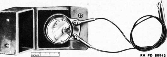
Figure 209-Ammeter (for Electric Brakes) A162447
otherwise unserviceable. The set should be kept complete at all times by requisitioning new parts for those used. Try each part as soon as practicable after received, to see that it fits the materiel properly. For listing of organizational spare parts for the 40-mm gun and carriage, see SNL A-50.
b. Care of spare parts is covered in section VII of this manual.
116. ACCESSORIES.
a. Accessories include the tools and equipment required for such disassembling and assembling as the using arms are authorized to perform, and for cleaning and preserving the gun and carriage. Accessories should not be used for purposes other than those prescribed, and when not in use should be properly stored.
b. There are a number of accessories, the names or general characteristics of which indicate their use. Others embodying special features or having special uses, are described in the following paragraphs.
117. ACCESSORIES FOR 40-MM GUN AND CARRIAGE.
a. Ammeter (for Electric Brakes). This ammeter (fig. 209) is used for measuring the current taken by the electric brakes of the carriage. It is used by connecting one terminal of the meter to one wire, and the other terminal of the meter to the point to which the wire is normally attached. When the current is supplied to the brakes, this meter registers the current flowing through the brakes.
b. Artillery Gun Book. This artillery gun book (0.0. Form 5825) is used for the purpose of keeping an accurate record of the materiel. It must always remain with the materiel regardless of where it may be sent. The book is divided as follows: record of assignment, battery commander's daily gun record, inspector's record of examination, as well as forms to be filled out in case of premature explosion. This book should be in possession of the organization at all times, and its completeness of records and its whereabouts are the responsibility of the battery commander. It must also contain date of issuance of
267
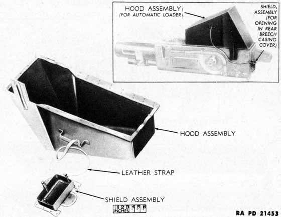
Figure 210-Automatic Loader Hood and Shield C95025
the materiel, by whom issued, and the place where issued. If a new gun is installed on the carriage, all data recorded in the old book with reference to sights, carriages, etc., must be copied into the new book before the old book is relinquished. Complete instructions on how to make entries in the artillery gun book are contained therein.
NOTE: Record of assignment data must be removed and destroyed prior to entering combat.
c. Automatic Loader Hood and Shield. This hood and shield (fig. 210) consists of a large steel hood assembly to which is fastened by a leather strap, a steel shield assembly. It fits over the feed guides and the opening in the rear breech casing cover when the gun is not in use, protecting the automatic loader against dirt and weather.
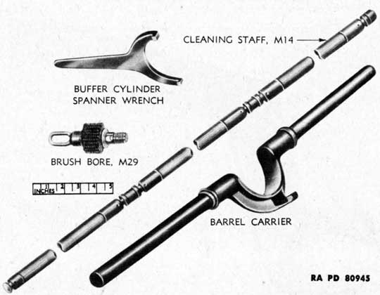
d. Barrel Carrier (C95032). This carrier (fig. 212) consists of two tubular steel handles which are inserted into a cradle. The handles are held in position in the cradle by straight pins that go completely through cradle and handles. The carrier is used to support the rear of the barrel assembly when removing it from and installing it in the breech ring.
e. Bore Brush M29 (B240944). This bore brush (fig. 212) consists of a spiral bristle brush with a nut on one end. Its use is to oil the bore of the gun.
f. Buffer Cylinder Spanner Wrench (A228073). This wrench
268
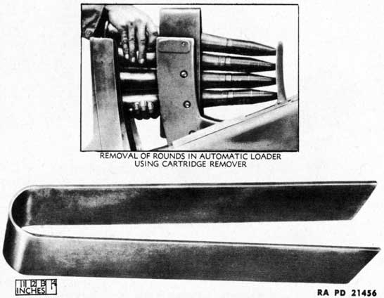
Figure 211-Cartridge Remover B200491
(fig. 212) is constructed of steel having an over-all length of 6.75 inches. Its use is disassembly and reassembly of buffer cylinder on the under side of the loading tray.
g. Cartridge Remover. This remover (fig. 211) is used to remove cartridges from the automatic loader. The remover is U-shaped in appearance. When in use, it is pressed over the cartridges and forces the feed and stop pawls of the automatic feed loader device clear, allowing removal of the cartridges. The remover and cartridges are removed together, out of the top of the loader, the pawls being depressed clear.
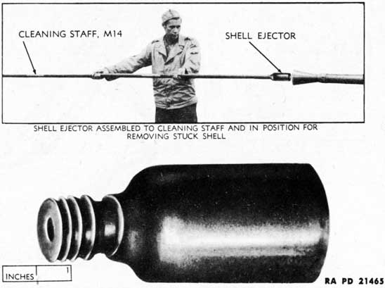
h. Cleaning Staff M14 (C97385). The cleaning staff, 144 inches long (fig. 212), consists of three wooden sections. It is used with the bore brush for cleaning bore of gun. The bore brush is removed and the shell ejector substituted when removing stuck shells from gun chamber.
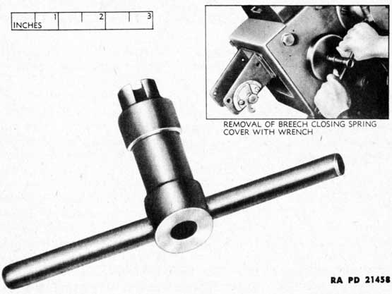
i. Closing Spring Cover Wrench. This wrench (fig. 213) consists of a body, handle, rivet, and spline. These parts when assembled constitute a T-shaped wrench used to remove the cover from the breech ring closing spring assembly.
j. Electric Brake Control Set M2 (C121778). This set is supplied with the gun carriage and utilized when the gun carriage is
269
Figure 212-Accessories for 40-mm Gun and Carriage
Figure 213-Closing Spring Cover Wrench A228074
270
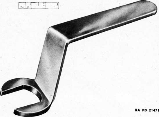
Figure 214-Equilibrator Rod Nut Wrench B198554
towed by a 2 1/2-ton truck (prime mover). This set is operated by the driver of the truck.
k. Equilibrator Rod Bushing Nut Wrench. This single-end wrench (fig. 214) which has a handle with two right-angle bends, is used to adjust the compression of the equilibrator springs, also to remove and replace the equilibrator rod jam nut and bushing nut.
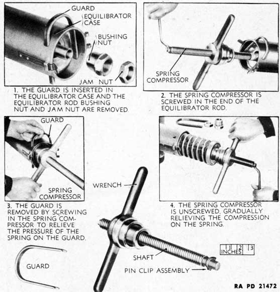
l. Equilibrator Spring Compressor and Guard. The equilibrator spring compressor (fig. 215) is composed of a threaded shaft, pin clip assembly, guard, and a wrench to which is assembled a bearing, a screw, and two collars. One end of the shaft is threaded and is smaller then the body of the shaft so that it may be screwed into the end of the equilibrator rod assembly with a wrench used on the opposite (shoulder) end of shaft. The shaft is locked in place with the pin clip assembly. The equilibrator spring is compressed by screwing up the wrench on the shaft. The guard, which is inserted through holes in the equilibrator case, is used to hold the compression of the spring after the equilibrator case cover has been opened and the two equilibrator rod assembly nuts have been removed prior to the insertion of the spring compressor. Compression of the spring may be relieved by unscrewing the wrench on the shaft.
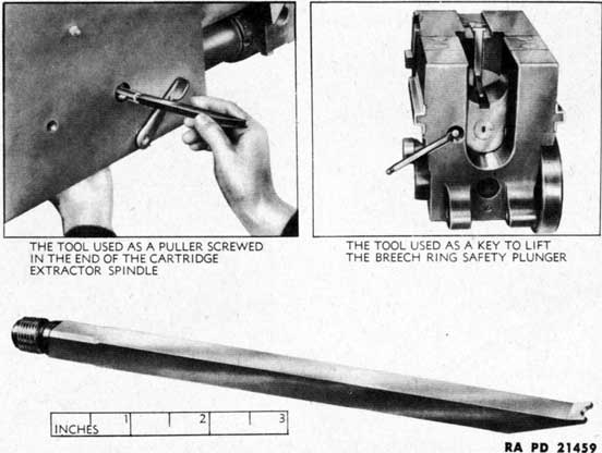
m. Extractor Spindle and Safety Plunger Key Puller. This puller (fig. 216) is constructed from 3/8-inch bar steel. It has an over-all
271
Figure 215-Equilibrator Spring Compressor C95677
length of 7 1/2-inches. It is used to lift the breech ring safety plunger during the removal of the breechblock and cranks. It is also used for insertion and removal of the extractor spindle from the breech ring.
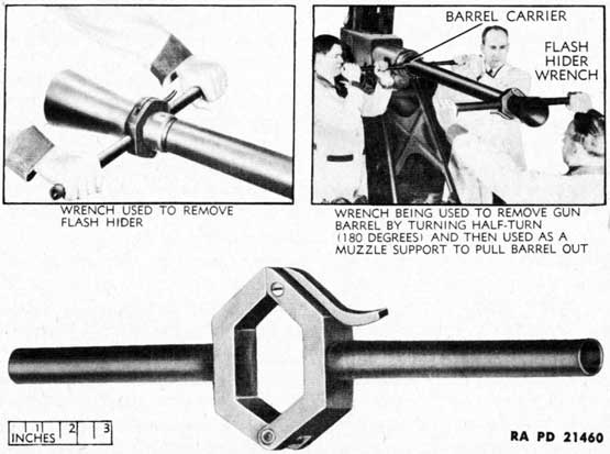
n. Flash Guard Wrench. This wrench (fig. 217) consists of two tubular handles, two jaws, a pin, and catch assembly. To use, release the catch by pressing downward. This allows the jaws to rotate on the pin. When open, place on the rear hexagonal portion of the flash hider, close jaws, which automatically fasten the catch. The wrench is then in position for removal of the barrel or flash hider.
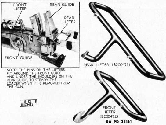
o. Front and Rear Loader Lifters. These two lifters (fig. 218) are of all metal welded construction. The larger of these two lifters is hooked to the rear portion of the automatic loader, the other to the fore part. When in this position, two men can remove the automatic loader assembly from the gun.
272
Figure 216-Extractor Spindle and Safety Plunger
Key Puller A228093
Figure 217-Flash Guard Wrench C95038
273
Figure 218-Front B200472 and Rear B200471 Loader Lifters
Figure 219-Hand Cartridge Extractor A228060
274
Figure 220-Shell Ejector A298763
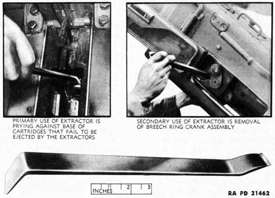
p. Hand Cartridge Extractor. This extractor (fig. 219) is of all metal construction having an over-all length of 13.43 inches. The end of the tool bent at approximately a 20-degree angle is used to extract cartridges from the barrel should cartridges fail to be ejected by the extractors. Raise the top cover of the breech casing to accomplish afore-mentioned extraction. The end formed at right angles to the major part is used to remove the outer breech ring crank assembly.
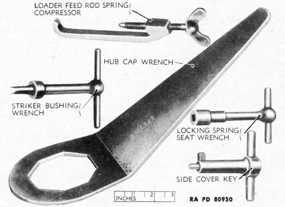
q. Hub Cap Wrench. This wrench (fig. 222) has an octagonal shaped opening at one end and a 30-degree offset handle at the other end. It is used for removing the hub caps from the wheel hubs.
r. Loader Feed Rod Spring Compressor. This compressor (fig. 222) consists of a jaw and screw. Its use is to compress the feed rod spring during the assembly and disassembly of the feed rod holders and feed rods to replace a broken or weak loader feed rod spring.
s. Locking Pin Seat Wrench. This wrench (fig. 222) T-shaped in appearance, is composed of a body and handle. It is used to unscrew spring seat allowing removal of breech ring safety plunger.
t. Shell Ejector. This ejector (fig. 220) is used to remove live shells stuck in the chamber of the gun tube with the rotating band wedged in the origin of rifling. The ejector is bored at one end and shaped to suit the shoulder of the shell and clear the fuze; the other
275
Figure 221 - Shell Pusher C95031
Figure 222-Accessories for 40-mm Gun and Carriage
276
Figure 223-Striker Protrusion Gage A276650
end has a screw-threaded projection to fit the socket of the cleaning staff. The ejector is screwed on the cleaning staff and inserted into the muzzle of the gun tube. The shell is then pushed out of the gun tube chamber by gradually forcing the cleaning staff-shell ejector assembly to the rear. The hand operating lever should be held fully to the rear in order to depress the breechblock fully. The person removing the stuck shell should stand as much as possible to the side of the muzzle as a safety precaution.
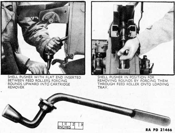
u. Shell Pusher. This pusher assembly (fig. 221) consists of a handle, brace, and pusher. The brace is securely welded to the handle approximately 3.5 inches from the pusher, which is fastened by a pin to the working end of the handle. This pusher assembly is used to unload cartridges remaining in the automatic loader at the conclusion of firing. There are two methods by which this may be accomplished:
(1) Force the cartridges between the feed rollers on to the loading tray (with the rammer cocked and the hand operating lever in the rear position) by means of the pusher, using the feed pawls as a fulcrum. The hand operating lever must be rotated to the rear each time a cartridge is forced between the feed rollers; this is necessary to release the feed catches.
(2) Insert the prepared flat end of the pusher into the rear of the
277
automatic loader between the feed rollers, and force the cartridges upward into the cartridge remover (fig. 211). Care must be taken not to use undue pressure when forcing the rounds upward.
v. Side Cover Key. This key (fig. 222) is of all metal construction having a bar handle. Its use is to lock and unlock the side cover. To use, insert into opening provided in side cover, exerting just enough pressure against spring tension to allow turning, thereby releasing catch.
w. Striker Bushing Wrench. This wrench (fig. 222) consists of a body and handle and is used to remove the loading tray bolt spring seat, breechblock firing pin spring cover, and loading tray attaching bolt.
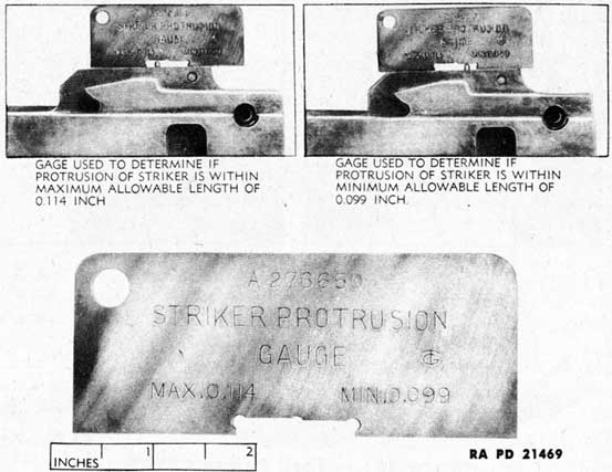
x. Striker Protrusion Gage. This gage (fig. 223) is used to determine if the length of protrusion of the striker or firing pin is within the specified limits (0.114 in. max., 0.099 in. min.). When placing the gage over the firing pin against the face of the breechblock, it can be determined in two steps whether the length of protrusion is less than the minimum allowable 0.099 inch or more than the maximum allowable 0.114 inch. Firing pins that do not fall within these limits should be replaced.
Section XIII STORAGE AND SHIPMENT
118. PREPARATION FOR DOMESTIC SHIPMENT.
a. General. The 40-mm Automatic Gun M1 and Carriages M2 and M2A1 (AA) can be shipped and stored either with or without the gun mounted. All precautions should be taken to prevent corrosion during shipment and storage, to keep the recoil mechanism exercised, and to prevent the deterioration of rubber during storage. The materiel should be prepared for both shipment and storage as directed in subparagraph h, below.
b. Preparation of 40-mm Automatic Gun M1 and Carriages M2 and M2A1 (AA).
(1) LUBRICATION. The materiel should be completely lubricated before shipment or storage in accordance with lubrication instructions as directed in section VI.
(2) CLEANING.
(a) The materiel shall be thoroughly cleaned and made free of all foreign matter, using SOLVENT, dry-cleaning, or a soap solution.
(b) Special attention should be given to breech and firing mechanism, and where possible, a partial disassembly of these components should be made to insure thorough cleaning.
278
(c) Apply SOLVENT, dry-cleaning, by scrubbing with a clean brush or wiping with clean saturated cloths.
(d) Apply soap solution by vigorously brushing or scrubbing the surfaces thoroughly until all traces of contamination have been removed. Rinse the cleaned surfaces with clean, hot water and dry thoroughly.
(e) Avoid contact of bare hands with the cleaned surfaces.
(3) PAINTING. Painted surfaces that have become checked, pitted, or rusted must have the rust spots removed and the surfaces repainted.
(a) Removing Rust Spots. The following may be used in removing rust spots:
1. CLOTH, abrasive, aluminum-oxide, for cleaning finished and unfinished external surfaces where wear of the parts cleaned will not affect the functioning of the mechanism.
2. CLOTH, crocus, for removing rust or stain and polishing parts of the breechblock and firing mechanism and other finished surfaces of metal.
(b) Application of PRIMER, Synthetic, Rust-inhibiting (AXS750). Apply a liberal coating of PRIMER, synthetic, rust-inhibiting over entire area of the cleaned surfaces to be repainted as follows:
1. Brushing or spraying. PRIMER, synthetic, rust-inhibiting, should be used on bare metal as a base coat for synthetic enamel. It may be applied either by brushing or spraying. The primer will brush satisfactorily as received or after the addition of not more than 5 percent by volume of THINNER, paint, volatile mineral spirits, TT-T-291. For spraying, the primer may be thinned with not more than 15 percent by volume of THINNER, paint, volatile mineral spirits, TT-T-291. Allow to dry thoroughly.
(c) Sandpapering Surfaces. Sandpaper the primed surfaces with PAPER, flint, class B, No. 00, and wipe all particles of dust from surfaces.
(d) Application of Enamel. Apply coat of ENAMEL, synthetic, olive-drab, lusterless, and allow to dry thoroughly before the materiel is used.
(4) APPLICATION OF PRESERVATIVE. NOTE: Application of preservatives should be accomplished immediately after cleaning and drying. Rust-preventive compounds, light and heavy, used herein shall be brought to the proper consistency by heating before application.
(a) Apply a coating of COMPOUND, rust-preventive, light, to interior portions of breech mechanism. Apply a coating of COMPOUND, rust-preventive, heavy, to all exterior portions of the breech.
(b) Thoroughly swab the bore of the gun with COMPOUND, rust-preventive, light.
(c) External Unpainted Surfaces.
279
1. Use COMPOUND, rust-preventive, thin film, on external unpainted surfaces of the carriage that are not highly finished, critical, or operating, and from which preservative need not be completely removed before materiel is placed in operation. This compound will be applied by brushing or spraying without heating or solvent dilution.
2. Use COMPOUND, rust-preventive, heavy, on external unpainted, critical operating surfaces of the carriage from which preservative must be completely removed before materiel is placed in operation.
(5) COVERS. Install breech and muzzle covers supplied with the materiel, and fasten securely. Using TAPE, adhesive, nonhygroscopic, wrap that portion of tube adjacent to the end of muzzle cover and over the end of cover, sealing the muzzle end of the gun. If covers are not available, the muzzle and breech ends of the gun shall be sealed using two layers of PAPER, greaseproof, wrapping, and one of PAPER, Kraft, wrapping, waterproofed. Apply TAPE, adhesive, nonhygroscopic, over paper completely sealing the openings.
(6) MISCELLANEOUS. Free end of electric brake jumper cable and coupling shall be taped and tied securely to the drawbar.
(7) GENERAL INSPECTION. Make a systematic inspection just before shipment or storage, and list all broken or missing items that are not repaired or replaced, and attach this list to the materiel.
119. LOADING AND BLOCKING MATERIEL ON RAILROAD CAR.
a. General. All loading and blocking instructions as specified herein are minimum, and are in accordance with the Association of American Railroads, "Rules Governing the Loading of Commodities on Open Top Cars, Special Supplement, Revised 1 March 1943," containing the "Rules Governing the Loading of Mechanized and Motorized Equipment and Major Calibre Guns."
b. Instructions.
(1) INSPECTION. Railroad cars must be inspected to see that they are suitable to carry loads to destinations. Floors must be sound and all loose nails or other projections not an integral part of the car should be removed.
(2) RAMPS. Permanent ramps should be used for loading the materiel when available, but when such ramps are not available, improvised ramps may be constructed of rail ties and other available lumber.
(3) HANDLING.
(a) Cars loaded in accordance with specifications given herein must not be handled in hump switching.
(b) Cars must not be cut off while in motion, and must be coupled carefully and all unnecessary shocks avoided.
(c) Cars must be placed in yards or sidings so that they will be subjected to as little handling as possible. Separate track or tracks,
280
when available, must be designated at terminals, classification or receiving yards, for such cars, and cars must be coupled at all times during such holding and hand brakes set.
(4) PLACARDING. Materiel not moving in combat service must be placarded, "DO NOT HUMP."
(5) CLEARING LIMITS. The height and width of load must be within the clearance limits of the railroads over which it is to be moved. Army and railroad officials must check all clearances prior to each move.
(6) MAXIMUM LOAD WEIGHTS. In determining the maximum weight of load, the following shall govern, except where load weight limit has been reduced by the car owner:
Marked Capacity of Car (Pounds)
Total Weight of Car Load (Pounds)
Load Weight (It. wt. of car to be deducted)
40,000
66,000
66,000
60,000
103,000
103,000
80,000
136,000
136,000
100,000
169,000
169,000
140,000
210,000
210,000
200,000
251,000
251,000
EXAMPLE:
Capacity of car
100,000 lb
Total weight of car and load
169,000 lb
* Light weight of car (to be subtracted)
37,000 lb
Permissible weight of load
132,000 lb
NOTE: When loading railroad cars, materiel shall be so loaded as to require a minimum number of cars. To accomplish this, various types of materiel may be loaded on the same car provided all have the same destination.
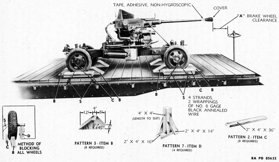
(7) BRAKE WHEEL CLEARANCE (A, fig. 224). Each railroad car must be loaded with a resulting brake wheel clearance of at least 6 inches in front, at each side and at the top. Brake wheel clearance shall be increased as much as is consistent with proper location of load.
(8) BRAKES. After loading and bracing the materiel, set the hand brakes.
(9) TIRES. Tire pressure shall be increased to 55 pounds per square inch.
(10) TYPE OF CARS. Flat, box, or drop end gondola cars may be used.
(11) DRAWBAR REMOVAL. Drawbar should be removed and secured to floor of railroad car by strapping with No. 8 gage, black annealed wire or flat steel strapping. Attach wire to floor by wrapping around blocks and nailing the blocks to the floor. Secure flat steel
* This marking is stenciled on each side of car indicated as "LT.WT."
Load must be so placed on the car that there will not be more weight on one side of the car than on the other. One truck of the carrying car must not carry more than one-half of the load weight.
281
Figure 224 - Method of Blocking 40-mm Automatic Gun M1 and Carriage M2 and M2A1 (AA) on Railroad Car
282
strapping that is not punched for nailing to floor by means of anchor plates attached to the car floor.
(12) GUN POSITION. Place gun in its traveling position with the gun stay in place.
(13) OUTRIGGER COVERS. Outriggers should be positioned for traveling with the covers in place over the hinge joints for protection from dirt and weather.
c. Blocking. All item reference letters given below refer to the details and locations in figure 224.
(1) PATTERN 3, ITEM B (EIGHT PIECES OF PATTERN 3 REQUIRED). Place one pattern 3 at the front and one at the rear of each wheel. The 45-degree portion of the block shall be placed next to the tire. Nail the heel of the pattern to the car floor with three 40-penny nails and toenail that portion under tire to car floor with two 40-penny nails before patterns 2 are applied.
(2) PATTERN 2, ITEM C (EIGHT PIECES OF PATTERN 2 REQUIRED). Place two patterns 2 on each side of the carriage against the outside of each tire. Nail the bottom pattern to the car floor with three 40-penny nails and the top pattern to the pattern below with three 40-penny nails.
(3) PATTERN 7, ITEM D (FOUR PIECES OF PATTERN 7 REQUIRED). Place one pattern 7 under the axle near the inside face of each wheel. These patterns should be cut so as to fit snugly between the car floor and the axle to relieve partially the weight from the tires. Nail each pattern to the car floor with six 40-penny nails.
(4) STRAPPING, ITEM S. Secure each wheel by passing wire consisting of four strands, two wrappings of No. 8 gage, black annealed wire through two openings in the wheels and securing the wire to the stake pockets on each side of the car. Twist tie with rod or bolt enough to remove slack. The openings in the wheels through which the wire passes should be approximately the same distance from the car floor. NOTE: When drop end gondola car is used, apply strapping in similar fashion, and attach to the floor by use of blocking or anchor plates.
120. LIMITED STORAGE INSTRUCTIONS.
a. When the materiel is stored uncrated, preparation will be in accordance with paragraph 118 h.
b. Periodical Inspections. Periodical inspections shall be made while the materiel is stored, to note among other things, general condition, missing parts, and the need for repairs. If found to be corroding at any part, the entire procedure as given herein under paragraph 118 b will be repeated.
c. Inspect the tires, repair any leaks that have developed, and inflate, if necessary.
283
Section XIV OPERATION UNDER UNUSUAL CONDITIONS
121. GENERAL.
a. Because of the different climates in which this materiel may be expected to operate, special instructions are given in this section for three regions, namely: Arctic, temperate, and tropical.
b. In certain cases, the prescribed instructions may not apply; for example, a tropical climate may be experienced in a temperate region. In cases of this nature, the instructions as to the classification of the climate in which the materiel is operating is left to the judgement of the ordnance officer. He is cautioned, however, that only extended, and not temporary, periods of climatic conditions govern the classification.
c. Manufacturing arsenals and plants should lubricate the materiel on assembly as prescribed in the lubrication guides (figs. 104 and 105). If the materiel is to be used in a climate other than temperate, the precautions in paragraphs 119 and 120 should be taken.
d. Materiel, previously lubricated for a colder climate than the one in which the materiel is to be used, should be relubricated with lubricants prescribed for use in that climate.
e. Materiel, previously lubricated for a warmer climate than the one in which the materiel is to be used, should be completely cleaned of all lubricants and relubricated with the lubricants prescribed for use in that climate.
122. TROPICAL CLIMATES.
a. The bore of the gun should be cleaned and oiled more frequently than usual when operating in hot climates. Temperature changes will cause condensation of moisture in the air on metal, and cause rusting. If condensation occurs on other metal parts of the gun and carriage, wipe them dry and coat with oil as required to prevent rusting.
b. Materiel should be inspected frequently when being operated in hot, moist areas. Cloth covers and other items which may deteriorate from mildew, or be attacked by insects or vermin should be aired and dried often.
c. Lubrication. Lubricate the materiel and check the levels of lubricants in gear cases more frequently when operating in hot climates. Heat will cause lubricants to thin out and deteriorate more quickly; gear cases and other lubricant-retaining devices may leak when the lubricant is hot. Use the lubricants prescribed for temperatures over 32 F as instructed in section VI.
d. Tires. Tires should be checked at frequent intervals to ascertain that the pressure is not above that which is prescribed, 45 pounds per square inch. Tires must be kept out of the direct rays of the sun
284
as much as possible. They should be covered to protect them from prolonged exposure to the sun.
e. Ammunition. Ammunition should be kept cool, and always out of the direct rays of the sun. Moisture-resistant seals should not be broken until ammunition is to be used.
NOTE: Extreme heat is often accompanied by other adverse conditions. Refer to paragraphs 121 and 122.
123. ARCTIC (SUB-ZERO) CLIMATES.
a. When the weapon is operated at sub-zero temperatures, special precautions must be taken in its care and maintenance to avoid poor performance and/or total functional failure, and in some instances, damage to both materiel and personnel. The materiel can be operated efficiently if the instructions given here are followed, even when average temperatures below zero degree F prevail. These instructions also should be followed when sluggish or stiff operation of the materiel indicates the advisability of adopting them at higher temperatures.
b. Introduction to Low Temperature Lubrication.
(1) Lubricating oils stiffen progressively as temperature drops until a point is reached at which they solidify. As stiffness increases, the power required to move bearing surfaces and gears in contact with the oil multiplies rapidly until movement becomes impossible. When solidification occurs, the moving parts cut a channel through the solid oil leaving the rubbing surfaces dry and unlubricated. Before friction can develop enough heat to liquefy the oil and reestablish an oil film, bearing and gear tooth surfaces may score and fail completely.
(2) Similar action takes place where rubbing surfaces are fed by an oil pump. The stiffened oil flows too slowly, or not at all, to the pump inlet and the oil already in the feed lines cannot be forced to the bearings. Oils, prescribed for use in artillery materiel at high temperatures, are designed to maintain adequate body at those temperatures. In most instances, they become too stiff at low temperatures for satisfactory operation. They must therefore be completely replaced in cold weather with lighter oils which will remain fluid at the lowest expected operating temperatures.
(3) Grease is a combination of soap and oil. The soap acts as a sponge to hold the oil in place, thus preventing leakage which might occur if oil alone were used. As temperature decreases, both oil and soap stiffen and retard the movement of parts. In cold weather, therefore, greases which cause minimum drag must be used.
(4) The presence of only a small quantity of warm weather grease may immobilize bearings and prevent the manipulation of the gun at sub-zero temperatures. When sub-zero temperatures are expected, all grease used in temperatures above zero degrees F must be removed
285
from bearings and gear cases and replaced with the specified low temperature products. Once grease has solidified, it cannot be removed from bearings or gear cases without the application of enough heat to melt it, or the disassembly of the unit and the washing of the parts with SOLVENT, dry-cleaning.
c. Mechanical Condition. Since metals contract and expand with temperature change and the amount of expansion and contraction varies with different metals, the clearance between bearing surf aces consisting of dissimilar metals is considerably less at sub-zero than at higher temperatures. In preparing artillery for sub-zero operation, therefore, care should be taken that parts are aligned properly and normal clearances exist. This applies not only to bearings but also to mechanisms employing packings around rotating or reciprocating shafts or rods. Lack of attention to this may result in binding which will make mechanisms stiff or inoperative, regardless of the lubricant used. Scored or rough bearing surfaces also interfere with easy action and should be smoothed in preparing materiel for low temperature operation.
d. Cleanliness. Cleanliness is imperative. Rust, dirt, and gummy oil and grease in bearing clearances reduced by low temperature will interfere with the proper feed of lubricant. This will cause stiff action, if not complete stoppage. In winterizing materiel, therefore, assemblies and mechanisms must be disassembled sufficiently to permit thorough removal of old oil, grease, and foreign matter. Cleaning is most efficiently done by washing with SOLVENT, dry-cleaning, employing brushes and scrapers where necessary. Field experience has proved that neglect in cleaning small linkages, bearings, and other similar parts may cause malfunctioning and stoppages in sub-zero weather.
e. Timeliness. Placing of materiel in proper mechanical condition requires time for necessary disassembly, repair, and cleaning, and must be carefully done. The approach of low temperature must be anticipated far enough in advance to permit completion of the conditioning before the onset of sub-zero temperatures.
f. Prescribed Lubricants. The following materials will be used for the lubrication and preservation of the gun and carriage at temperatures below zero degree F, and above zero degree F where stiff action indicates their necessity. Refer to SNL K-1 for specification designations of products available through the ordnance provision system.
(1) OIL, LUBRICATING, PRESERVATIVE, LIGHT. All bearings, gear cases, and mechanisms for which the prescribed oil at normal temperatures is engine oil. Miscellaneous hand oiling.
(2) OIL, LUBRICATING, FOR AIRCRAFT INSTRUMENTS AND MACHINE GUNS. Oil-lubricated parts in directors, sighting instruments, and other fire control equipment.
286
(3) OIL, HYDRAULIC. All hydraulic systems for speed gears and remote control oil gears.
(4) GREASE, O.D., No. 00. All bearings, gears, and mechanisms for which GREASE, O.D., No. 0, is prescribed at temperatures above
32 F.
(5) GREASE, LUBRICATING, SPECIAL. Grease-lubricated mechanisms of fire control materiel.
(6) GREASE, GENERAL PURPOSE, No. 2. Wheel bearings at all temperatures.
(7) CLEANER, RIFLE BORE. May be used for cleaning gun bores after firing if a cleaning solution is not available.
(8) SOLUTIONS, SPONGING. Cleaning gun bores after firing.
(9) SOLVENT, DRY-CLEANING. Cleaning grease and oil from all mechanisms and parts. May also be used for diluting OIL, engine, SAE 10, in engine crankcases.
g. Low Temperature Lubricating Instructions. To insure adequate lubrication and satisfactory performance of artillery materiel in cold weather, the following instructions must be followed when sub-zero temperatures are expected:
(1) BALL AND ROLLER BEARINGS, GREASE LUBRICATED. It is impossible to replace warm weather grease in ball and roller bearings by forcing in the grease prescribed for low temperatures. Attempts to do this result in overloading the bearings with unsuitable lubricant which will congeal at low temperatures and immobilize the moving parts. These bearings must be removed by disassembly from the materiel, washed thoroughly in SOLVENT, dry-cleaning, to remove all traces of heavy grease, dried, and then repacked with the prescribed lubricant in accordance with instructions in War Department Lubrication Guide, No. 61.
(2) BALL AND ROLLER BEARINGS, OIL-LUBRICATED. Oil-lubricated ball and roller bearings preferably should be removed and cleaned. If this is impractical, a thorough flushing with SOLVENT, dry-cleaning, followed by application of the prescribed oil generally will give satisfactory results. Oil sumps and reservoirs must be drained, flushed, and filled with the proper oil. The wicks of wick-fed bearings should be removed and saturated with OIL, lubricating, preservative, light, before reassembling.
(3) PLAIN JOURNAL BEARINGS AND BUSHINGS. It is preferable to disassemble these bearings, not only to remove thoroughly all heavy oil and grease, but also to smooth all roughness and to test for adequate clearance between shaft and bearing. Where disassembly is impracticable, heavy lubricant usually can be forced from the bearings by thorough flushing with OIL, lubricating, preservative, light. Reservoirs and wick feeds must be cleaned completely and
287
refilled to the prescribed level with the proper oil.
(4) GEARS, OIL-LUBRICATED. Where gears are inclosed in oiltight gear cases filled with oil, all oil will be drained, the case flushed with SOLVENT, dry-cleaning, and the case refilled to the proper level with OIL, lubricating, preservative, light. Where no drain or level plug is provided, the gear cases will be disassembled by ordnance maintenance personnel.
CAUTION: Do not fill above the prescribed level as the surplus oil will cause unnecessary drag on the movement of the gears.
(5) GEARS, GREASE-LUBRICATED. Since it is practically impossible to wash heavy grease out of a gear case by flushing, grease-filled cases will be disassembled, cleaned, and refilled by ordnance maintenance personnel.
h. Elevating Arc. It is often found that snow will collect on
the elevating arc. This snow will cake under the pressure of the gears, forming ice and interfering with the elevation of the piece. This snow must be removed by vigorous brushing with a stiff bristle or wire brush before elevation of the piece is attempted.
i. Gun Bore.
(1) Cleaning of a gun bore after firing cannot be accomplished in the normal manner at temperatures below 32 F because the water will freeze in the tube. If the cleaning can be done with the tube hot, and hot water is available, normal SODA ASH or soap solutions can be used. Otherwise, it will be necessary to add alcohol, glycerine, or COMPOUND, antifreeze, to the normal SODA ASH or soap solution to prevent freezing.
(2) To ten parts by volume of cleaning solution, add the number of Darts of one of the antifreezes shown below:
Temperature F
Glycerine or Alcohol or Ethylene Glycol
20
2 1/2
2
2
10
5
4
3 1/2
0
6 1/2
6 1/2
5
-15
10
9
7 1/2
-30
13
16
10
-40
16
27
12
(3) When available, CLEANER, rifle bore, may be used. However, this solution will freeze at temperatures below 32 F. If frozen, it must be thawed and shaken well before using. Closed containers should not be filled to more than 75 percent of capacity in freezing weather. Completely filled containers will burst when contents freeze. In an emergency, SOLVENT, dry-cleaning, or OIL,
288
lubricating, preservative, light, may be used, but neither is as effective as the cleaning solution.
(4) In applying OIL, lubricating, preservative, light, to the bore after cleaning, care must be taken to work the oil in well so that it will reach all surfaces of the lands and grooves. When the gun is brought into a heated shop, condensation will occur on all metal surfaces. After the gun reaches shop temperature, the tube and all other bright metal parts must be wiped dry and recoated with oil to prevent rusting.
j. Firing Pin and Attendant Parts, Breechblock and Breech Casing Firing Mechanism Parts. Not only must extreme cleanliness be maintained, but oil must be applied sparingly to obtain proper functioning in cold weather. The best method of application, after cleaning thoroughly with SOLVENT, dry-cleaning, is to wipe the rubbing surfaces of the parts with a clean cloth which has been wet with oil and wrung out. Use OIL, lubricating, preservative, light, for normal winter temperatures. In extreme cold, use OIL, lubricating, for aircraft instruments and machine guns.
k. Recoil Cylinder. The recoil cylinder is filled with a mixture of 60 parts by volume of OIL, hydraulic, and 40 parts by volume of OIL, recoil, light. This mixture will be used in all temperatures.
l. Oil Gears. Although hydraulic oil is considered satisfactory for sub-zero temperatures, it may be expected to stiffen to some extent at low temperatures. Oil gears should be exercised for periods of at least 30 minutes, often enough to assure that the materiel functions properly and is ready for action at all times. This exercising will warm the oil and gears.
m. Sighting and Fire Control Equipment. Sighting and fire control equipment is normally lubricated for operation over a wide range of temperatures. This equipment should be exercised frequently during periods of low temperature to insure proper functioning. If any equipment does not function properly, the ordnance maintenance personnel should be notified.
n. Emplacement. Gun carriages and supports for fire control
equipment freeze quite solidly into the ground in cold weather. As a result, considerable labor is required to dig the equipment if the battery position must be changed. To prevent this, coat all surfaces that contact the ground with waste grease or very heavy oil before emplacing. Sources of waste lubricant are the gear casings of guns and automotive equipment, the drainings and scrapings of these being used. They are obtained when the materiel is relubricated for cold weather.
o. Electric Brakes. Before traveling, the safety switch should always be checked for proper operation because low temperatures
289
seriously reduce the efficiency of the "hot-shot" batteries. Partly discharged batteries must be replaced with new and fully charged units. The plugs must be kept clear of ice and snow or it will be impossible to insert them in their sockets.
p. Tires. Tires should be checked at frequent intervals to insure that the pressure is not below that prescribed, 45 pounds per square inch.
q. Dry Cell Batteries. Dry cell batteries are very unsatisfactory after exposure for a few hours to low temperatures.
r. Inspection. Inspections should be made daily because of the limited amount of lubricant used in cold weather operations.
s. Operation. Keep the loading platform free of ice or snow to prevent injury to personnel caused by insecure footing. The bore should be inspected frequently for frosting or congealed lubricants. The flash hider cover and the automatic loader hood and shield should be in place as much of the time as the rate of fire permits to exclude snow and moisture from the interior of the weapon.
124. EXCESSIVELY MOIST OR SALTY ATMOSPHERE.
a. When the materiel is active, clean and relubricate the bore and exposed metal surfaces more frequently than is prescribed for normal service. Moist and salty atmospheres have a tendency to emulsify oils and greases and destroy their rust-preventive qualities. Inspect parts frequently for corrosion. Keep the flash hider cover and the automatic loader hood and shield in place as much of the time as firing conditions permit.
b. Cloth covers and other items that may deteriorate from dampness should be inspected frequently and dried as often as possible.
c. When the materiel is inactive, the unpainted parts should be covered with a film of COMPOUND, rust-preventive, heavy, and should be inspected daily for traces of the formation of rust. All covers should be in place.
125. EXCESSIVELY SANDY OR DUSTY CONDITIONS.
a. When the weapon is active in dusty or sandy areas, remove lubricants from the elevating rack and from exposed sliding parts and bearing surfaces. Surface lubricant will pick up sand and dust, forming an abrasive which will cause rapid wear. Lubricate the parts after action.
b. Inspect and lubricate the materiel more frequently when operating in sandy or dusty areas. Exercise particular care to keep sand and dust out of the mechanisms and oil receptacles when carrying out inspecting and lubricating operations and when making
290
adjustments and repairs. Cover the cooling slots in the forward portion of the breech casings of those guns having these slots. Seal all openings in the rear portion of the breech casing. Keep all covers in place as much of the time as firing conditions permit. Shield parts from flying sand and dust with tarpaulins or the carriage cover during disassembly and assembly operations.
c. Should the prescribed lubricant for the gun bore prove inadequate in preventing rusting of the bore surfaces, OIL, lubricating, preservative, medium, may be used for oiling of the bore during periods of inactivity.
291
Section XV REFERENCES
126. PUBLICATIONS INDEXES.
The following publications indexes should be consulted frequently for latest changes or revisions of references given in this section and for new publications relating to materiel covered in this manual:
a. Introduction to Ordnance Catalog (explaining ASF Cat. SNL system)
ORD 1 IOC
b. Ordnance Publications for Supply Index (index to SNL's)
ASF Cat. ORD 2 OPSI
c. Index to Ordnance Publications (listing FM's, TM's, TC's, and TB's of interest to ordnance personnel, OPSR, MWO's, BSD, S of R's, OSSC's, and OFSB's; and includes Alphabetical List of Major Items with Publications Pertaining Thereto)
OFSB 1-1
d. List of Publications for Training (listing MR's, MTP's, T BA's, T/A's, FM's, TM's, and TR's concerning training)
FM 21-6
e. List of Training Films, Film Strips, and Film Bulletins (listing TF's, FS's, and FB's by serial number and subject)
FM 21-7
f. Military Training Aids (listing Graphic Training Aids, Models, Devices, and Displays)
FM 21-8
127. STANDARD NOMENCLATURE LISTS.
a. Ammunition.
Ammunition, fixed and semifixed, all types, including subcaliber for pack, light and medium field artillery, including complete round data
SNL R-1
Ammunition for antiaircraft artillery
SNL P-5
Ammunition instruction material for antiaircraft, harbor defense, heavy field, and railway artillery, including complete round data
SNL P-8
b. Care and Maintenance.
Cleaning, preserving and lubricating materials; recoil fluids, special oils, and miscellaneous related items
SNL K-1
Soldering, brazing and welding material, gases and related items
SNL K-2
292
c. Materiel.
Director, A.A., M5A2 and M6 (British)
SNL F-209
Gun, automatic, 40-mm, M1 and carriage, gun 40-mm, M2 (A.A.)
SNL A-50
Indicator, range, Mk. I, Navy
SNL F-287
Quadrant, gunner's, M1
SNL F-140
Sight, computing, M7
SNL F-276
Sight, correctional, Mk. V
SNL F-286
Small arms, automatic gun, trench mortar and field artillery sighting equipment and fire control instruments