Section III DESCRIPTION AND FUNCTIONING OF CARRIAGE
21. GENERAL.
a. The 40-mm Gun Carriages M2 and M2A1 (AA) are of the 2-axle, 4-wheel trailer type. A drawbar with a standard drawbar lunette forms the connection between the carriage and the prime mover. The carriage is equipped with 4-wheel electric brakes operated from the prime mover, and manually operated mechanical brakes on the rear wheels. The lighting equipment includes taillight, stop, and blackout lights.
b. The top carriage supports the gun, loading platform, firing mechanism, and all parts of the elevating and traversing mechanism which travel in azimuth with the gun. The top carriage can be traversed and the gun can be elevated either manually or electrically. Traverse is continuous. The gun may be depressed and elevated from minus 6 degrees to plus 90 degrees (the elevating limit switch limits power elevation to approximately plus 85 degrees and depression to approximately zero degree).
c. Independent spring suspension is used on all wheels. Axles are spring-loaded to assist in lowering the carriage to firing position and in raising it to traveling position. In firing position, the carriage is leveled by means of four built-in leveling jacks and is anchored by four stakes driven into the ground.
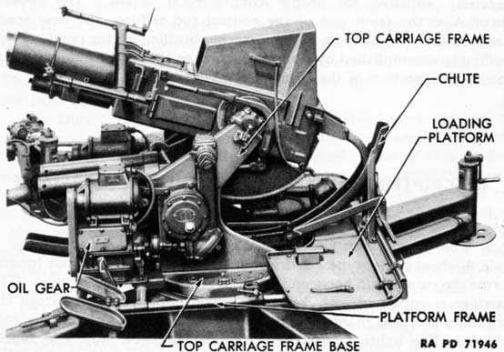
22. TOP CARRIAGE.
a. The top carriage (fig. 47) consists of two built-up top carriage frames welded to a rigid cast top carriage frame base. The frames are connected near the center by a large cross tube which also houses the elevating mechanism worm wheel pinion. At the tops of the frames and back of center are the top carriage trunnion bearings and caps which support the tipping parts of the weapon. At the angular points at the front of the frames are the trunnion bearings for the equilibrators.
b. The right top carriage frame carries the traversing gear
74
Figure 47-Top Carriage and Loading Platform Frame
mechanism and the elevating limit switch. The elevating gear mechanism is mounted on and through the left top carriage frame.
c. The loading platform frame is carried on the top carriage frame base. Two levels, used to level the carriage for action, are also mounted on the left side of top carriage frame base.
d. The top carriage rotates in azimuth on the top carriage ball or roller bearing and is driven by the traversing gear assembly.
23. PLATFORM FRAME ASSEMBLY.
a. The loading platform frame (fig. 47) is a tubular frame of rectangular shape with two intermediate cross members. These cross members fit the cradles into lugs and are also attached to the lugs on the top carriage frame base.
b. The side members carry the seats and footrests for the elevating and traversing mechanism operators. These seats are adjustable, fore and aft, up and down. The loading platform covers the rear portion of the frame. The oil gears are mounted on plates carried on the two front cross members. The cartridge chute, azimuth indicator, and power synchronizing mechanism (slewing handle) are supported by the platform and frame.
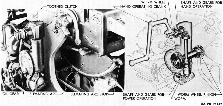
24. ELEVATING MECHANISM.
a. The elevating mechanism (fig. 48) consists of the hand elevating mechanism group assembly and the elevating worm and worm
75
Figure 48 - Elevating Mechanism - Assembled and Phantom Views
76
Figure 49-Equilibrators
wheel mechanism assembly. It is mounted on the outside of the left top carriage frame. The hand elevating mechanism is manually operated through a toothed clutch on a shaft turned by a double hand crank. Rotation of the shaft is transmitted through gearing to the elevating mechanism worm wheel pinion which meshes with the elevating arc fastened to the under side of the breech casing. The pinion is enclosed in the tubular brace between the top carriage frames. The elevating arc is provided with stops limiting the movement of the gun in elevation.
b. The elevating worm and worm wheel mechanism is connected to the oil gear power drive, permitting the gun to be elevated by power. The gears operate in oil-filled housings to provide means for constant lubrication. The elevating limit switch, mounted on the right gun trunnion frame, may be adjusted to limit the elevation and depression of the gun when operated by power.
c. An elevation plate, calibrated in degrees, is mounted on the breech casing a portion of the way around the left trunnion.
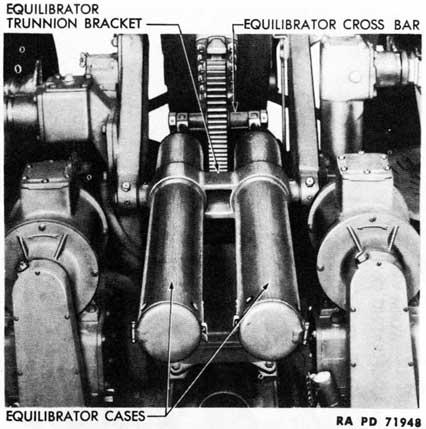
25. EQUILIBRATORS.
a. Two spring type equilibrators (fig. 49), operating as a unit, are provided to neutralize the unbalanced weight of the weapon and reduce the effort required to elevate it. The assembly is located under the gun and between the top carriage frames.
77
b. Each equilibrator consists of a tubular case containing a set of three springs held in compression on an equilibrator spring rod. The two cases are held in the equilibrator trunnion bracket which is supported in trunnions in the front edges of the top carriage frames. The two equilibrator spring rods are pivoted on the equilibrator cross bar which is clamped in and projects from each side of the elevating arc.
c. The equilibrator springs are compressed as the gun is depressed, counterbalancing the muzzle-heavy weight of the tipping parts and eliminating the need for braking their descent. The energy stored in the compressed springs is released as the gun is elevated, the expanding springs exerting a pull on the elevating arc and assisting in elevating the gun.
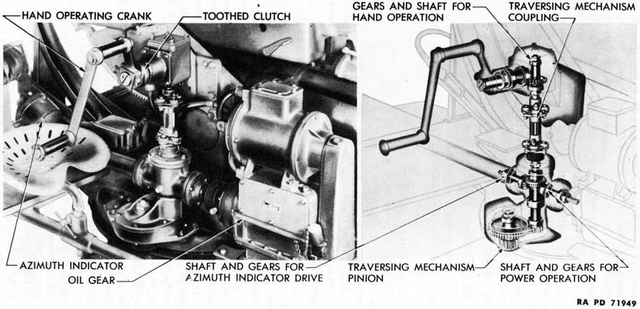
26. TRAVERSING MECHANISM.
a. The traversing mechanism (fig. 50) consists of the hand traversing mechanism group assembly and the traversing mechanism group assembly.
b. Higher gear ratios in the hand traversing mechanism of the Gun Carriage M2A1 result in hand traversing that is approximately three times as fast as that of Gun Carriage M2. The principal differences between the hand traversing mechanisms of the two carriages are a larger hand traversing mechanism gear case and long and short hand traversing mechanism bevel gears of higher ratio on the Gun Carriage M2A1.
c. The hand traversing mechanism is mounted on the outside of the right top carriage frame and is manually operated through a toothed clutch on a shaft turned by a double hand crank. The rotation of this shaft is transmitted by bevel gears in the hand traversing mechanism gear case through the flexibly coupled traversing mechanism pinion shaft to the traversing gear reduction mechanism assembly to which the traversing mechanism is splined. The traversing mechanism pinion meshes with the top carriage traversing ring gear on the chassis frame base. The top carriage is rotated in azimuth by the traversing mechanism pinion being rolled around the circumference of the stationary top carriage traversing ring gear.
d. The traversing mechanism power drive extension shaft is geared to the traversing mechanism pinion shaft and connects the traversing mechanism to the azimuth oil gear, permitting the top carriage to be traversed by power. The azimuth indicator drive shaft is also geared to the traversing mechanism pinion shaft. (The azimuth indicator is described in par. 96 h.) All gears operate in oil-filled gear cases to provide constant lubrication.
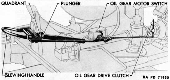
27. POWER SYNCHRONIZING MECHANISM (SLEWING HANDLE).
a. The power synchronizing mechanism (fig. 51) provides a means
78
Figure 50 - Traversing Mechanism - Assembled and Phantom View
for rapid traverse (slewing) when the weapon is being traversed manually. It also provides a means for bringing the gun into approximate alinement with the director in order that the azimuth oil gear may be engaged.
b. The power synchronizing mechanism is mounted on the rear cartridge chute body support which is mounted on the rear of the loading platform. When the power synchronizing mechanism handle is depressed, it throws the traversing oil gear motor switch after engaging the oil gear drive clutch. Raising the handle disengages the power drive and permits the top carriage to be swung around (slewed) rapidly. The handle is held in either raised or depressed position by the engagement of a spring-loaded plunger in a notched quadrant on the right side of the handle.
28. OIL GEAR UNITS.
a. The azimuth oil gear and the elevation oil gear supply controlled driving power for traversing and elevating the gun. They are units of the on-carriage equipment of the Remote Control System M5, designed for use with the 40-mm Gun Carriages M2 and M2A1 (AA). They are identical except for a conversion which can be made by the using arm personnel. They are fully described in section X, which also gives instructions for operation, maintenance, tests, adjustments, and instructions for conversion.
b. Each oil gear unit consists of an oil gear or hydraulic power mechanism, driven through a roller chain by a 0.6-horsepower, 115-volt, alternating-current motor which is mounted on top of the oil gear.
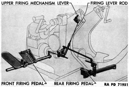
29. FIRING MECHANISM.
a. The firing mechanism on the top carriage (fig. 52) actuates the firing mechanism in the gun. This mechanism can be operated by applying pressure to either the front or rear firing pedals.
80
Figure 52-Firing Mechanism on Carriage-Phantom View
Figure 53-Chassis Frame With Outriggers Folded
b. The front firing pedal is located just above the right footrest on the left side of the platform frame. It is interconnected with the rear firing pedal located just back of the seat on the same side of the gun. Pressure on either pedal is transmitted through linkage to the firing lever rod which runs up the left top carriage frame to the upper firing mechanism lever which contacts the firing crank plunger in the left gun trunnion.
c. When pressure is released, the firing pedals are returned to their normal positions by springs. Either firing pedal may be depressed without disturbing the position of the other.
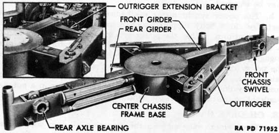
30. CHASSIS FRAME.
a. The chassis frame (fig. 53) of the carriage is cross-shaped with
81
Figure 54-Top Carriage Roller Bearing
a circular center chassis frame base. Long, built-up girders extend to the front and rear from the central structure. These carry the front and rear axles and suspension units, the front and rear compensating springs which aid in lowering and raising the carriage to firing and traveling positions, and the front and rear leveling jacks.
b. Short built-up arms extend to each side of the center chassis frame base. The outriggers are hinged to the side arms. Leveling jacks are mounted on ends of the outriggers. When outspread, the outriggers give sidewise stability to the carriage in firing position.
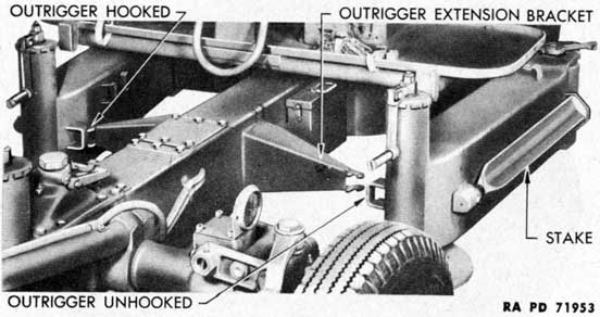
c. On carriages of late manufacture, and on those so modified, chassis frame outrigger extension brackets with double outrigger hooks (insert, fig. 53) are welded to both sides of the front chassis frame girder. When the outriggers are folded and engaged by the ends of these brackets, continuous traverse of the top carriage is permitted when the weapon is in traveling position. On unmodified carriages of early manufacture, the outriggers, when folded, are engaged by hooks welded directly to the front chassis frame girder; traverse is restricted in traveling position.
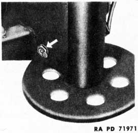
d. The circular center chassis frame base has a flat top surface. On this is mounted the top carriage ball or roller bearing which supports the top carriage, loading platform frame, and the gun with its operating equipment.
82
Figure 55-Outrigger-Folded Position
Figure 56-Outrigger-Extended Position
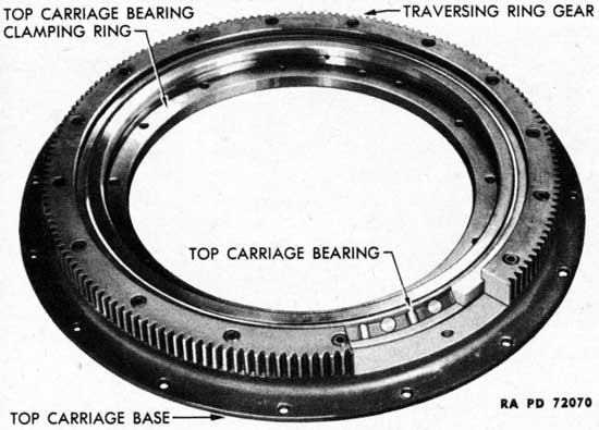
e. Top Carriage Ball or Roller Bearing and Traversing Gear.
(1) The top carriage rotates on a large ball or roller bearing (fig. 54) mounted within the traversing ring gear. The upper race of the ball bearing (or the inner race of the roller bearing), which carries the top carriage, is clamped by the bearing clamping ring to the frame base of the top carriage. The lower race of the ball bearing (or the outer race of the roller bearing) is held in the traversing ring gear which is attached to the flat, circular center chassis frame base by the stationary top carriage base.
(2) The top carriage is rotated in azimuth by the traversing mechanism pinion, which is mounted on the top carriage, being tolled around the circumference of the stationary traversing ring gear.
83
f. Outriggers.
(1) The outriggers are built-up box girders, similar in construction to the short transverse arms of the chassis frame to which they are hinged. The outrigger eccentric hinges permit the outriggers to be extended when the mount is in firing position (fig. 56) or folded when the mount is in traveling position (fig. 55). These hinges give inward and outward movement to the outriggers which permits them to be locked in both positions.
(2) The upper and lower plates of each outrigger extend over the top and bottom of the end of its side girder. These plates terminate in wedge-shaped toes. There are brackets on the tops and bottoms of the side members into which the toes of the plates fit when the outriggers are in firing position. Brackets on the front sides near the ends of the outriggers engage hooks to lock the outriggers in traveling position.
(3) On the top of each outrigger is a jointed outrigger eccentric hinge lever which is keyed to the eccentric hinge spindle. Each lever is equipped with a holding bracket and a stop. With the outrigger in firing position, when the lever is swung toward the rear of the carriage until its stop is contacted, the eccentric sleeves on the hinge spindle cause the outrigger to move outward. The toe of the plate is withdrawn from the bracket on the side girder. The outrigger may then be swung forward to traveling position. Here the bracket on the outrigger is caught by hooks. When the outrigger eccentric hinge lever is returned to its holding bracket, the outrigger is locked in position.
(4) On carriages of early manufacture, the brackets on the sides of the outriggers are engaged by double outrigger hooks welded to both sides of the front chassis frame girder. The result is that the outriggers are drawn so closely to the girder that traverse is restricted when the weapon is in traveling position.
(5) On carriages of late manufacture, and on those which have been modified, chassis frame outrigger extension brackets with double outrigger hooks (fig. 55) are welded to both sides of the front chassis frame girder. When the outrigger brackets are engaged in the hooks on the extension brackets, the outriggers are locked at such angles as to permit continuous traverse of the weapon when in traveling position.
(6) On carriages of early manufacture, the outrigger hinges in traveling position were fitted with welded steel outrigger hinge covers. Carriages are currently being fitted with canvas outrigger hinge covers.
g. Stakes.
(1) Four triangular-shaped chassis stakes (figs. 55 and 56) are provided to anchor the carriage to the ground in firing position. In traveling position, one of these stakes is carried on the outer side
84
Figure 57 - Leveling Jack With Crank Extended
of each outrigger and two stakes are carried on the right side of the rear chassis frame girder. In firing position, the stakes are inserted in double stake brackets welded to the forward sides of the outriggers, the right side of the front girder, and the left side of the rear girder.
(2) In traveling position, the points of the stakes are fitted into cavities in the spring-loaded plungers of the stake point and the heads of the stakes are held in brackets (fig. 56).
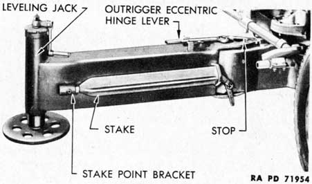
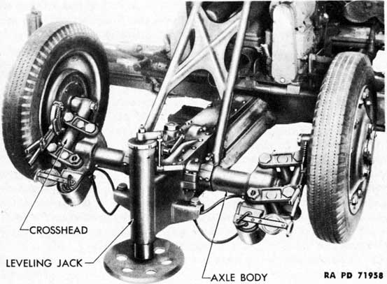
h. Leveling Jacks.
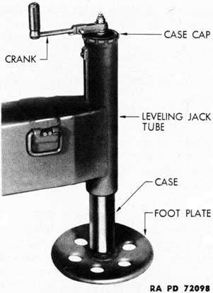
(1) Leveling jack bodies are welded to the ends of the outriggers (figs. 57 and 58) and front and rear girders. These bodies house the leveling jack cases, screws, and mechanisms. The leveling jacks provide a means for leveling the mount in firing position.
(2) Each jack has a circular foot plate to afford considerable contact with the ground, and a hinged crank which is extended to operate the jack (fig. 57) or is folded downward and fitted into grooves in the case cap to lock the jack in position (fig. 58). The handle is retained in extended and folded positions by a spring-loaded plunger. The foot plate has a ball and socket mounting to compensate for uneven ground and an outer flange and a number of flanged circular openings to prevent movement on the ground.
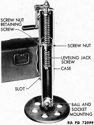
(3) The handle of the leveling jack is keyed to the leveling jack screw (fig. 58). When the handle is turned, the leveling jack screw
85
Figure 58 - Leveling Jack - Cutaway View
causes the leveling jack screw nut to move up or down. The screw nut is prevented from revolving with the leveling jack screw by the screw nut retaining screw which moves up and down in a slot in the leveling jack body. The leveling jack case which is attached to the screw nut, and the foot plate which is attached to the bottom of the case, are moved up and down in the leveling jack body by the action of the screw nut, lowering or lifting the weapon.
i. Other Units Mounted on Chassis Frame. The gun junction box (par. 96 c) is mounted on left side of the rear chassis frame girder, while the blackout light switch (par. 34 c) is mounted nearer the end on the same side of this girder. The battery container box (par. 32 d) is mounted near the center circular section on the left side of the front girder.
31. AXLES AND SUSPENSION.
a. In traveling position, the axles distribute the weight of the carriage to the wheels and house the spring suspension units. In addition, they may be rotated to lower and raise the carriage to firing and traveling positions. The front axle is also provided with a means of steering the carriage as it is being towed.
b. The front and rear axles are hollow tubes with bearing surfaces on which they support the carriage and seats for the parts which are attached to them. The axles support the carriage in the front chassis
86
Figure 59 - Front Axle - Traveling Position
Figure 60 - Front Axle - Firing Position
87
Figure 61 - Rear Axle - Traveling Position
Figure 62 - Rear Axle - Firing Position
88
Figure 63 - Spring Suspension - Cutaway View
swivel and the rear axle bearings. The front and rear chassis compensating springs, arcs, and locks assist in lowering and raising the carriage to firing and traveling positions, the drawbar and gun stay being used as levers in performing these operations.
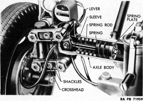
c. Spring Suspension.
(1) Each of the four wheels of the carriage has independent spring suspension, the coil spring for each wheel being housed inside its end of the axle (fig. 63). The front and rear suspension units are similar, the principal exception being that the front axle spindle shafts can be rotated in their cross heads to provide a means of steering similar to that employed in automobiles.
(2) The axles terminate in hollow, T-shaped heads. The axle cross head is attached to the top and bottom of the "T" by upper and lower shackles, permitting the cross head a limited up-and-down movement. Each front axle spindle shaft is mounted vertically in its cross head with the hub of a front axle spindle splined to the lower end of the spindle shaft. The rear axle spindles are keyed directly to hubs at the lower end of the rear axle cross heads.
(3) The axle shackle springs inside the axle bodies are compressed against the piston-like axle body sleeves by axle shackle spring rods and plates which are connected to axle shackle spring levers splined to the upper shackles. Any tendency of a wheel to move upward, as
89
Figure 64 - Front Chassis Compensating Spring, Arc, and Lock - Cutaway View
in striking a bump, is counteracted by the resistance of its lever tending to move outward and compress its spring.
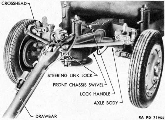
d. Front Chassis Swivel. The front chassis swivel (fig. 64) is a box-like structure with a tubular rear extension. The tubular end fits into a housing in the front end of the front girder and is secured by a collar. It not only supports the front axle but it houses the mechanism which permits the axle to be rotated about 140 degrees to allow the front part of the carriage to be raised and lowered.
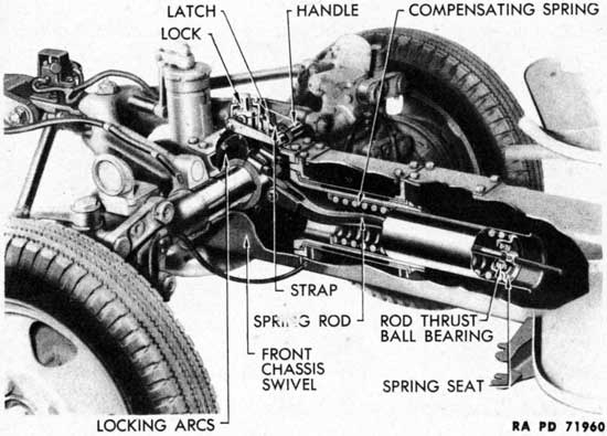
e. Front Chassis Compensating Spring, Arc, and Lock.
(1) The function of this mechanism (fig. 64) is to assist in the lowering and raising of the carriage and to lock the axle when the carriage is in firing or traveling position. It consists of a powerful compression spring in a housing mounted in the front chassis swivel, a compression rod and seat connected to a lug on the front axle locking arc assembly, two notched locking arcs firmly keyed to the front axle, and a spring-loaded lock actuated by a locking handle.
(2) The chassis compensating spring lock handle is eccentrically mounted to cause it to raise and lower the spring-loaded lock when the handle is rotated toward and away from the gun. The lock engages notches in the arcs to lock the axle in position. The handle is automatically held in locked position by a latch.
90
Figure 65 - Steering Mechanism
(3) Raising the lock handle lifts the lock from its notch in the arcs. When the front axle is rotated, using the draw-bar as a lever, the front end of the carriage is lowered to the ground against the compression of the compensating spring. Depressing the lock handle permits the lock to be inserted into one of five notches in both of the arcs and locks the axle in that position.
(4) When the locking handle is lifted and the drawbar is rotated away from the gun, the front axle is unlocked and rotated, and the carriage is raised with the assistance of the compressed compensating spring. Depressing the lock handle forces the lock into a notch in the arcs and the latch retains the handle, locking the carriage in traveling position.
(5) As additional assurance that the front and rear chassis compensating spring lock handles will not become unlocked inadvertently, a web strap and chassis clip have been provided for each lock handle on carriages of late manufacture and on those so modified. This strap and buckle are attached by means of the clip to one of the chassis compensating spring cover cap screws. The strap must be buckled around the bar of the lock handle to hold the handle in locked position at all times except when the handle is being operated.
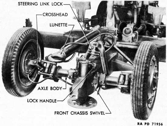
f. Drawbar.
(1) The drawbar (fig. 59) is a strong tubular member which serves to connect the carriage to the prime mover, to actuate the steering mechanism of the carriage, and to provide a lever for lowering
and raising the front part of the carriage. It is hinged to the steering drawbar link which is connected through the front axle yoke to the yoke bearings on the front axle.
(2) A lunette (fig. 60) is mounted in the forward end of the drawbar. In the earlier models, the lunette mounting was provided with rubber shock absorbing rings separated by steel washers, and was held in place in the drawbar by screws; in the later models, it is held by heavy rivets and does not have the rubber rings.
(3) To provide a rigid lever for raising and lowering the front part of the carriage, the drawbar, steering link, and front axle yoke are locked together. The drawbar steering link pin is inserted through holes near the front of the front axle yoke and near the rear of the steering link and the drawbar pin is inserted through holes near the front of the steering link and near the rear end of the drawbar.
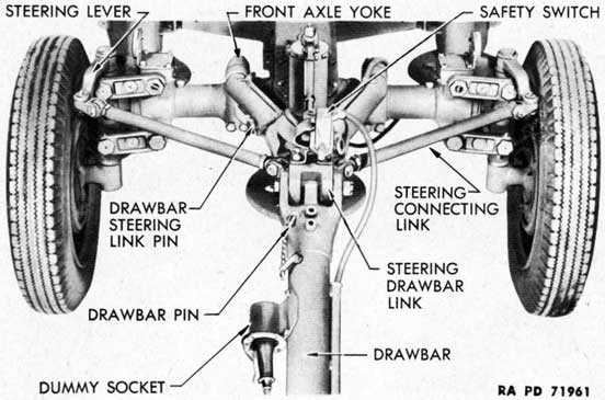
g. Steering.
(1) Steering of the carriage is accomplished by turning the front axle spindles in unison, in the manner that an automobile is steered. The front wheels are directed to the right and left by the steering drawbar link (fig. 65) which is connected to the steering levers on the front axle spindles by the tubes and clevises of the steering connecting link assemblies.
(2) The steering drawbar link is supported by and pivots in the front end of the front axle yoke which is fastened and keyed to the front axle. The link is pivoted from side to side by the drawbar. In traveling position, the front axle yoke is held horizontally by being
92
Figure 67 - Gun Stay - Traveling Position
locked to the front end of the front chassis swivel by the steering link lock (fig. 59).
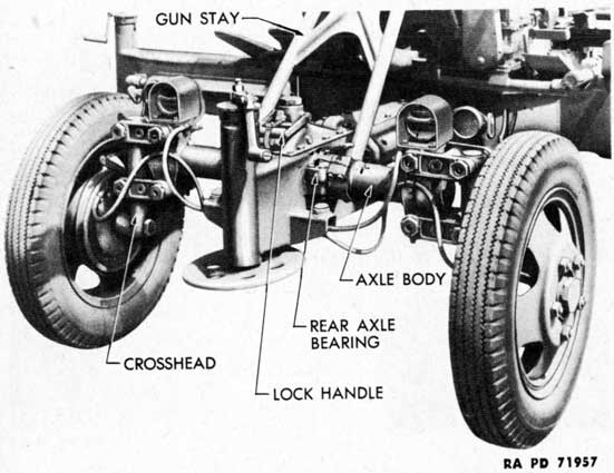
h. Rear Axle Bearing. The rear axle bearing not only affords a mounting for the rear portion of the carriage on the rear axle, but it permits the rear axle to be rotated in lowering and raising the carriage to firing and traveling positions.
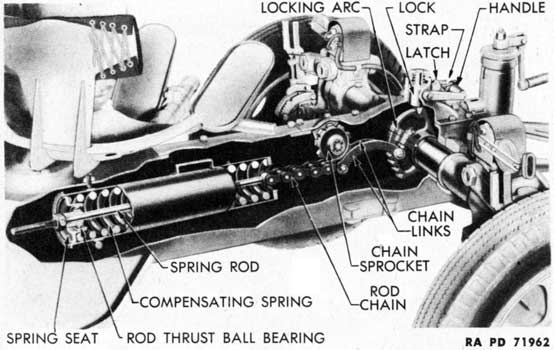
i. Rear Chassis Compensating Spring, Arc, and Lock.
(1) The function and operation of the rear chassis compensating spring, arc, and lock (fig. 66) are the same as those of the front chassis compensating spring, arc, and lock. The construction and action of the lock handle and lock are very much the same. There is some difference in the construction and action of the spring, arc, and other parts.
(2) The compression spring, encased in its housing, is held in the rear girder by trunnion pins and screws. The spring compression rod and seat are connected to a single locking arc by a short length of roller chain and a pair of links. The chain is carried under a ball bearing mounted sprocket when the axle is rotated to give a straight line pull on the spring compression rod. The gun stay is used as the lever for rotating the rear axle.
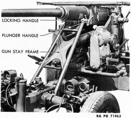
j. Gun Stay.
(1) The gun stay (fig. 67) is a tubular frame which holds the gun
93
Figure 68 - Electric Brake Mechanism and Brake Drum
rigidly in traveling position and serves as a lever for rotating the rear axle in lowering and raising the carriage. The lower end of the gun stay pivots on the rear axle.
(2) Spring-loaded plungers at the lower ends of the gun stay engage the rear axle to form a rigid connection and convert the stay into a lever for use in placing the carriage in firing or traveling position.
(3) In traveling position, threaded plungers in the upper end of the stay are engaged in recesses in the breech casing by turning the plunger (outer) handles. The plungers are locked in place by turning the plunger locking (inner) handles.
32. BRAKES.
a. General. The carriage is equipped with 4-wheel electric brakes actuated by current produced on the prime mover and conducted to the carriage by a detachable cable. They are applied separately from those on the prime mover by means of a controller and a load control switch. In case of a break-in-two between the prime mover and the carriage, the brakes are applied automatically by a safety switch with electrical current supplied by a dry cell battery carried on the carriage (subpar. d below). The rear wheels are equipped with separate hand-operated mechanical brakes.
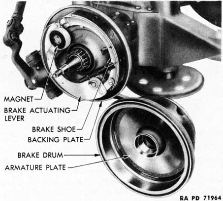
b. Electric Brake Mechanism.
(1) Each electric brake wheel unit (fig. 68) consists principally of
94
Figure 69 - Safety Switch and Dummy Socket
Figure 70 - Battery Container Box on Front Girder
an armature plate secured to the inside of the brake drum and rotating with it, and a magnet, brake actuating lever, and brake shoes mounted with springs to the stationary backing plate of the brake mechanism. The backing plate is mounted on a flange on the wheel spindle.
(2) The magnet is supported on the end of the brake actuating lever and is always in light contact with the armature plate. The lever is pivoted between the ends of the brake shoes and is capable of being moved backward or forward. It is returned to its normal position after it has been moved in either direction by the springs which retract the brake shoes from the drums.
(3) There is a stud on the under side of the lever at its pivoted end. This stud bears against either of two links attached to the brake shoes and presses the shoe attached to that link outwardly when the lever is moved, applying the shoe to the drum. Retracting springs withdraw the shoes from the drum when pressure upon their ends is released by the lever.
c. Electric Brake Functioning. When the brakes are applied, current is released which energizes the magnet (fig. 68). The magnet clings to and tends to revolve with the armature plate, causing the lever to move. The stud on the pivoted brake actuating lever presses one of the links attached to the end of a brake shoe, expanding the shoe against the brake drum and applying braking effort. The more current released, the tighter the magnet will cling to the armature plate and the harder the shoe is pressed against the drum. Application of the brakes during forward movement activates one brake shoe initially; the other brake shoe is activated initially during backward movement.
95
Figure 71 - Hand Brake Lever
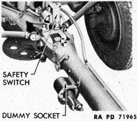
d. Safety Switch, Dummy Socket, and Battery Container.
(1) The safety switch (fig. 69) automatically applies the electric brakes on the carriage wheels in the event of a break-in-two between the carriage and the prime mover. The switch has a lever which is normally in the "off" or backward position; it can be pulled forward to the "on" position.
(2) On carriages of earlier manufacture, the safety switch, together with the dummy socket for the jumper cable, is located on a bracket mounted on the steering drawbar link. On carriages of later manufacture and those so modified, the safety switch is mounted on the steering drawbar link but the dummy socket for the jumper cable is mounted on the side of the drawbar.
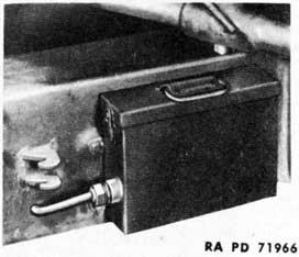
(3) The battery container box (fig. 70) is mounted near the center chassis frame base on the left side of the front chassis frame girder. It contains a dry cell battery to supply current to actuate the brakes through the safety switch in case of a break-in-two.
e. Safety Switch Functioning. When a break-in-two occurs, the safety chain, which connects the safety switch to the prime mover, pulls the switch lever forward. This closes the circuit from the dry cell battery to the brakes, energizes the brake magnets, and sets the brakes. The safety switch chain is provided with a spring clip which permits its being pulled from the switch lever without damage to the chain, after the lever has been pulled forward.
NOTE: The safety switch chain and the jumper cable are part of the equipment of the carriage and should be disconnected from the prime mover and retained with the carriage when the latter is uncoupled.
96
Figure 72 - Flat Base Rim Type Wheel
Figure 73 - Divided Rim Type Wheel
f. Hand Brakes.
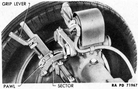
(1) The parking or mechanical hand brake mechanisms on the rear wheels are operated by hand brake levers (fig. 71) assembled to the brake backing plates. Each lever is secured in the engaged position by a spring-loaded gear sector pawl which engages the teeth of a hand brake sector. A grip lever is squeezed toward the hand brake lever to release the brakes.
(2) The hub of the brake lever is attached to the shaft of the emergency brake operating cam which contacts the emergency brake lever and link to force the brake shoe against the drum when the brake is applied.
33. HUBS, WHEELS, AND TIRES.
a. Hubs. Each wheel hub has an outer flange to which the brake drum and wheel disk are fastened by studs, and two inner chambers for the roller bearings which support the weight of the carriage on the axle spindles. The assemblies are retained on the spindles by the axle spindle washer and nut and the outer hub opening is closed by a hub cap.
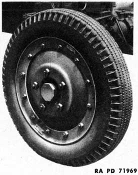
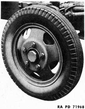
b. Wheels. Carriages have been equipped with two types of steel disk wheels. The truck and bus wheel (flat base rim type) (fig. 72) consists of a wheel disk and flat base rim. The tire is held on the rim by a rim flange locked by a split locking side ring. The transport combat (divided rim type) (fig. 73) consists of a wheel disk and
97
Figure 74 - Rear Lamp Fixtures
Figure 75 - Blackout Light Switch
base rim. The tire is held on the base rim by a side ring retained by 12 side ring bolt nuts. Both types of wheels are attached to the hubs by 5 wheel stud nuts. Wheel stud nuts on the right wheels have right-hand threads; those on the left wheels, left-hand threads.
c. Tires. Tires and tubes used on the carriage are size 6.00-20. The standard tire equipment is the 6-ply, heavy-duty, truck-bus type tire with standard heavy-duty tube and flap. Carriages of early manufacture were equipped with 6-ply, heavy-duty, truck-bus type tires and heavy bullet-resisting tubes. Some carriages were equipped with combat tires. In all cases, the pressure to be maintained in the tires is 45 pounds per square inch.
34 LIGHTING EQUIPMENT.
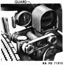
a. The light equipment (fig. 71) consists of two lamp fixtures with tail lamp guards and side and rear reflectors mounted on the tops of the rear axle cross heads, side reflectors mounted on the tops of the front axle cross heads, and a reflector mounted on the front of the cover.
b. The left lamp fixture houses the service taillight, service stop light, and a blackout taillight. The right lamp fixture houses a blackout taillight and the blackout stop light.
c. The lighting can be converted to either service or blackout by means of the blackout switch (fig. 75). It is located under the small
98
cover on the left side of the rear girder near the rear end. Turn the blackout switch shaft until the slot lines up with the letters "BO" (blackout) or "S" (service).