a. EXCESSIVE EFFORT REQUIRED TO ELEVATE OR DEPRESS GUN.
(1) Difficulty in elevating or depressing the gun may be caused by weak or broken springs, corrosion of the rods, improper adjustment and insufficient lubrication, or damaged equilibrator cases.
(2) Defective springs or rods will be replaced (pars. 65 and 67). Corrosion on the rods may be removed.
(3) For adjustment of the equilibrators, refer to paragraph 64 f and for lubrication refer to LO 9-252 or LO 9-252-1.
(4) Bent or damaged equilibrator cases will cause difficult operation and will be repaired or replaced as required (pars. 65 and 67).
b. IRREGULAR MOVEMENT OF GUN IN ELEVATION AND DEPRESSION.
(1) Jerky operation of the gun in elevation and depression may be caused by a loose or damaged crossbar or connectors, damaged parts, improper lubrication, or incorrect adjustment.
(2) To correct, tighten or replace defective parts (pars. 65 and 67), lubricate (LO 9-252 or LO 9-252-1), or adjust (par. 64 f) as required.
c. OTHER CAUSES FOR DIFFICULT OPERATION OF GUN. Defective elevating mechanism or elevating gear sector also affect operation of the gun in elevation. Refer to paragraphs 54 and 69.
63. Removal
a. If the equilibrators are to be removed for replacement or maintenance of other units and are not to be disassembled, elevate the gun about 80 degrees.
b. Place an equilibrator rod spacer (fig. 20) between each equilibrator rod end and the case and elevate the gun further to
147
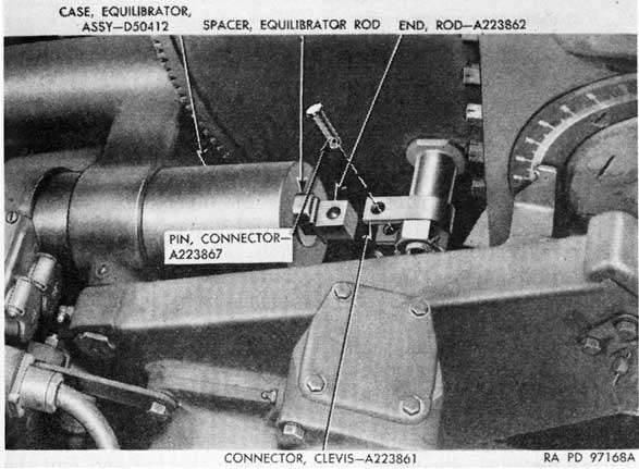
Figure 95. Removing equilibrator case with assembled parts.
hold the spacers in place and to relieve spring tension on the clevis connectors (fig. 95).
c. Engage the elevation hand crank and secure it to the platform or carriage to prevent the gun from dropping when the equilibrators are removed.
d. Remove the cotter pins and connector pins from the connectors.
e. Remove the equilibrators by withdrawing them from the equilibrator trunnion bracket. Before attempting to remove them, clean the equilibrator cases, scraping off excess paint or corrosion that might interfere with their removal. If the cases stick, insert a bar in the compressor guard openings and twist the case with the bar to loosen it. In extreme cases, it may be necessary to employ a block and tackle. Do not attempt to remove stuck cases by hammering them.
f. To remove equilibrator trunnion bracket, rotate it one-half turn so that small ends of taper pins are accessible, drive out the pins, and unscrew the trunnion pins. It may be necessary to detach tie bar from elevation oil gear to remove trunnion pin.
Note. Operations illustrated in figure 265 or also applicable to carriage M2A1.
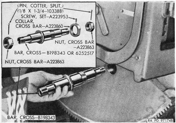
g. To remove equilibrator cross bar from elevating gear sector, remove cotter pins, nuts, and connector, then remove set screw from cross bar collar, and remove collar and cross bar (fig. 96).
148
64. Installation
a. Install the cross bar in the elevating gear sector and install the cross bar collar with set screw (fig. 96). Install the two connectors on the cross bar and install the cross bar nuts. Aline the holes for the cotter pins and install the cotter pins.
b. To install the equilibrator trunnion bracket, mount the bracket in position on the top carriage and install the two trunnion pins. Aline the trunnion pins for the taper pins and install the taper pins. If new trunnion pins are installed, taper pin holes must be drilled and reamed at assembly.
c. With the gun elevated and secured as described in paragraph 63, oil and install the cases, with assembled parts, in the equilibrator trunnion bracket.
Note. Position equilibrators on carriage so that cover catches are horizontal and the covers swing outward from each case.
d. Attach the rod ends to the clevis connectors with the connector pins and cotter pins.
e. Untie the hand crank and depress the gun to release the spacers installed, during removal, between the rod end and the cases (par. 63).
f. Using nut wrench-41-W-1578-100 (fig. 14) , loosen the jam nuts and turn the bushing nuts to compress the springs the correct amount to produce satisfactory operation of the gun in elevation. Torque measured at the elevating hand crank should not exceed 90 inch-pounds. Adjust both equilibrators the same. Tighten the jam nuts after the adjustment has been made.
65. Disassembly
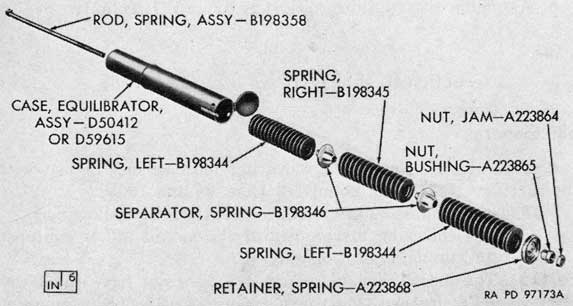
a. Refer to TM 9-252 for instructions on disassembly of equilibrators. Parts of equilibrator assembly are shown in figure 97.
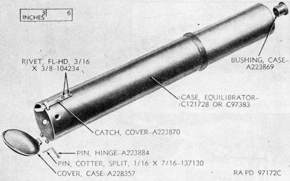
b. The equilibrator case assembly can be disassembled, if necessary, by removing the cover and the bushing (fig. 98). All other parts are welded to the case. Case assemblies of alternate design are found on some weapons.
66. Repair, Overhaul, and Rebuild
a. Clean the parts of the equilibrator assembly and inspect for wear or damage. Check parts (carriage M2A1) for surface treatment (par. 27).
b. Inspect the springs for breaks or cracks; replace, if broken or showing signs of fracture. Characteristics of springs for use on carriage M2A1 and mount M3 should be approximately as
149
Figure 96. Installing equilibrator cross bar.
follows: free height 11 11/16 to 13 3/16 inches, solid height not more than 3 7/8 inches, and load of 1,100 to 1,320 pounds at maximum compressed height of 4.134 inches. Lubricate springs with OD grease No. 0 for temperatures above +32° F. and OD grease No. 00 for temperatures below +32° F.
c. Inspect the rod and bushing nut for worn or damaged threads. Inspect bushing for wear or damage; if worn or out of shape. replace. Use a hammer type puller for removal.
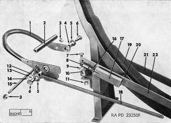
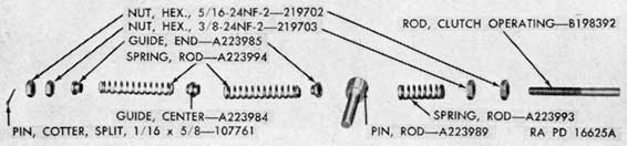
Figure 97. Parts of equilibrator assembly.
150
Figure 98. Parts of equilibrator ease assembly.
d. Examine the case assembly for dents or cracks and loose parts. If necessary to replace the catch, cut the two retaining rivets, install through staple on case, and rivet in position.
e. Check all parts for rust or corrosion. Remove such damage by polishing with crocus cloth.
f. Replace all parts that are broken or deformed.
67. Assembly
a. Assemble equilibrator case assembly, if disassembled (fig. 98).
b. Assemble the equilibrators (fig. 97) (TM 9-252).
Section II. ELEVATING MECHANISMS
68. General
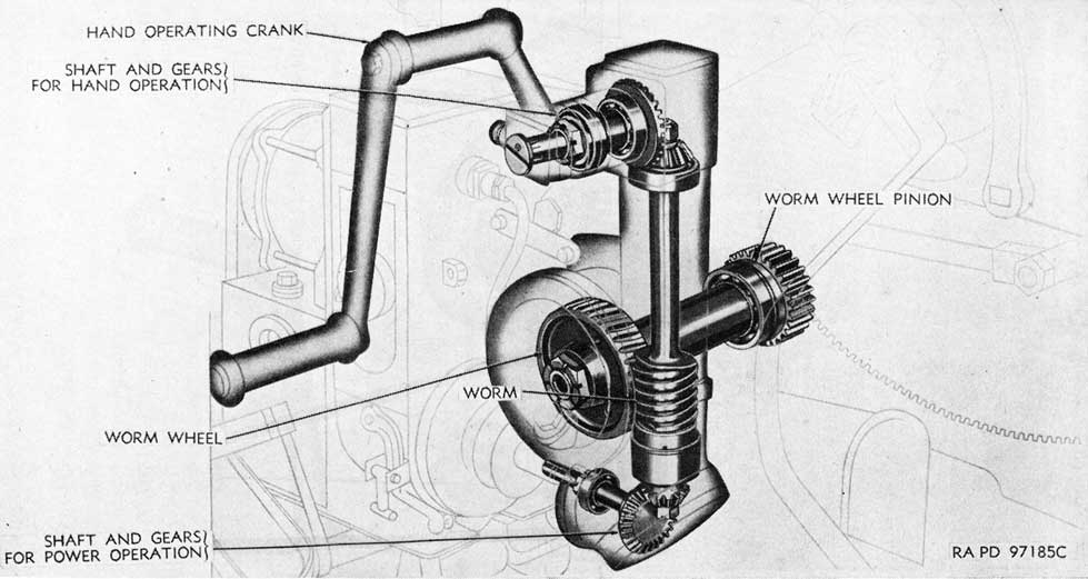
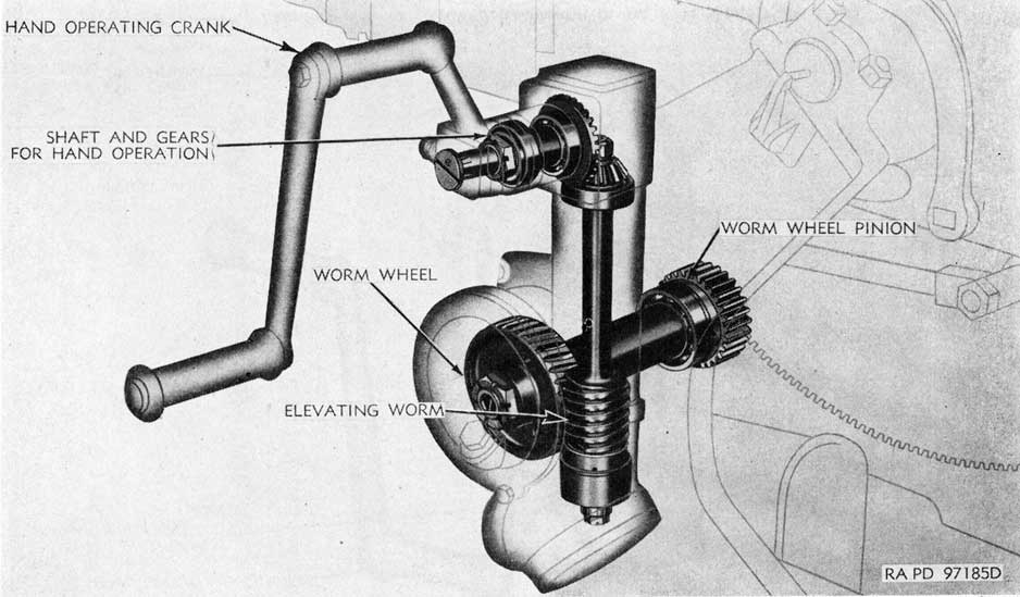
a. This section covers the elevating mechanisms in use with the carriage M2A1 and mount M3 (figs. 99 and 100).
b. These mechanisms are similar except for the following:
(1) The elevating mechanism of the mount M3 is equipped for manual operation only.
(2) The mechanism of mount M3 does not have the lower gear; instead, the worm spacer - A338605 is mounted on the worm.
151
Figure 99. Phantom view of elevating mechanism in use with the carriage M2A1.
152
Figure 100. Phantom view of elevating mechanism in use with the mount M3.
153
c. For differences between these mechanisms and that used with the mount M4, refer to paragraph 188.
d. The instructions given in this section pertain to the elevating mechanisms in use with the carriage M2A1 and mount M3, unless indicated otherwise.
69. Trouble Shooting
a. EXCESSIVE EFFORT REQUIRED TO ELEVATE OR DEPRESS GUN.
(1) Difficulty in elevating and depressing the gun may be caused by worn or damaged bearings, pinion, worm, or worm wheel or incorrect meshing of the worm and worm wheel.
(2) Replace worn or damaged parts (pars. 70 and 74).
(3) Correct mesh between the worm and worm wheel may be obtained by installing shims of correct thickness for the worm wheel (par. 74 a).
(4) This trouble may also be caused by faulty operation of the equilibrators (par. 62), damaged trunnion bearings, or incorrect mesh between the elevating gear sector and pinion (par. 54).
h. EXCESSIVE BACKLASH IN ELEVATING MECHANISM.
(1) This condition may be caused by worn gears, pinion, bearings, worm, and wheel.
(2) Check total backlash as described in paragraph 12, d and e before dismounting the mechanism. If backlash is excessive, correct by replacing worn parts (pars. 72 and 74) or by shimming (pars. 59 i and 100 k).
70. Removal
a. Place the gun at zero elevation and engage the gun stay (carriage M2A1) or secure the barrel assembly (mount M3).
b. Remove the elevation hand crank.
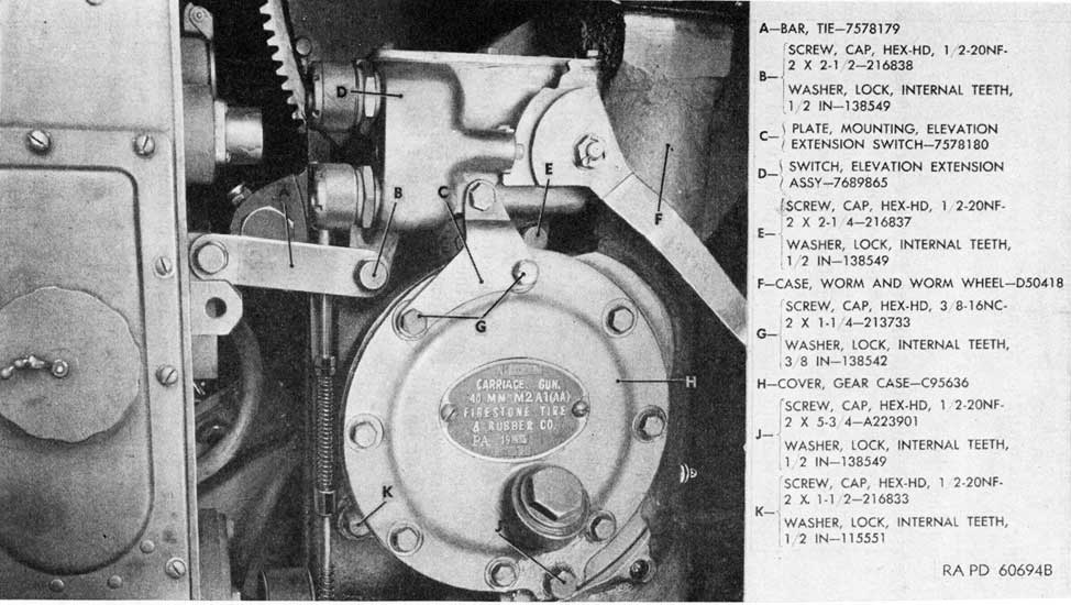
c. On carriage M2A1, disengage the tie bar (elevation oil gear) from elevation extension switch and gear case by removing cap screw and lock washer (fig. 101). Remove the nuts and screws that retain the oil gear on the platform and move the oil gear away far enough to disengage the oil gear coupling from the splined shaft of the bevel gear in the bearing adapter assembly. It is not necessary to remove the oil gear nor to detach the cables.
d. Remove the two cap screws with lock washers which secure the elevation extension switch mounting plate to the gear case cover (fig. 101).
e. Remove the two cap screws with lock washers that attach the gear case to the top carriage and the long cap screw with lock washer from the gear case cover (fig. 101). Remove elevation extension switch assembly with the mounting plate (fig. 101).
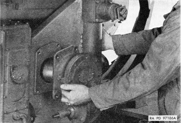
f. Pull the elevating mechanism straight away from the top carriage and remove (fig. 102). It may be necessary to pry the mechanism to start it. If so, be careful not to damage the gear case.
71. Installation
a. Place the assembly in position in the top carriage (fig. 102) and push into place, with the pinion meshed with the elevating gear sector. It may be necessary to operate the mechanism by hand to engage the sector and pinion.
b. Support the elevating mechanism in position and install the long screw with lock washer and the left lower screw with lock washer (fig. 101).
c. Push the elevation oil gear into position to engage the oil gear coupling with the splined shaft of bevel gear in bearing adapter assembly and install the retaining screws and nuts in the oil gear base (carriage M2A1). Check alinement of oil gear with coupling gage (TM 9-252).
d. Install elevation extension switch assembly with mounting plate by securing plate to gear case cover with two cap screws
156
and lock washers (fig. 101). Install right upper cap screw with lock washer to secure switch assembly and gear case to top carriage (fig. 101).
e. Place the tie bar in position on switch assembly and install the screw with lock washer (fig. 101).
72. Disassembly
a. HAND ELEVATING MECHANISM.
Note. The hand elevating mechanism can be removed and disassembled without removing the elevating mechanism.
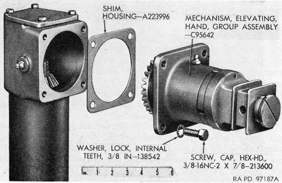
(1) Remove the cap screws with lock washers and remove the hand elevating mechanism group assembly and housing shim from the elevating mechanism case (fig. 103).
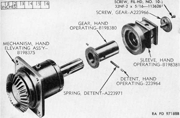
(2) Remove the screw which locks the gear screw and remove the gear screw (fig. 104). In some mechanisms, the screw-113626 and gear screw-A223966 are replaced by a cap screw-216971, internal teeth lock washer-111328, locking screw-112300, and gear washer-A287859 (fig. 250).
(3) Remove the hand operating sleeve, with the ring gear, from the hand operating gear (fig. 104). Do not lose the two hand operating detents and the detent spring (carriage M2A1). On some mounts M3, detents and spring are not used in the elevating mechanism; a spacer serves to keep the sleeve engaged with the inner gear. This is
Figure 103. Removal of hand elevating mechanism.
157
Figure 104. Parts of hand elevating mechanism.
satisfactory, since the mount M3 is operated only manually.
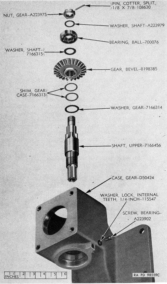
(4) Remove the hand operating gear from the splined portion of the bevel gear (figs. 104 and 105).
(5) Remove the set screw from the bearing cap and remove the cap (fig. 105), using the spanner wrench - 41-W3250-242 (fig. 14).
(6) Remove the cotter pin, unscrew the gear nut, and remove washer from the bevel gear (fig. 105).
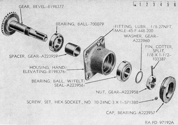
(7) Remove the bevel gear from the hand elevating housing and remove the ball bearing and gear spacer from the gear (fig. 105).
(8) Remove the other ball bearing from the housing (fig. 105).
b. POWER ELEVATING MECHANISM (CARRIAGE M2A1).
Note. The power elevating mechanism can be removed and disassembled without removing the elevating mechanism but only after the oil gear has been disengaged (par. 70).
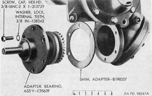
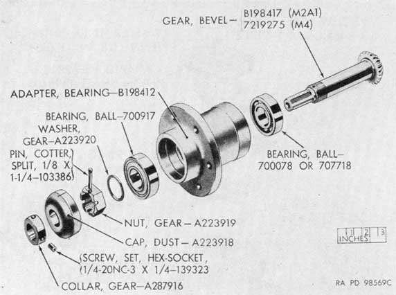
(1) Remove the six cap screws with lock washers from the adapter housing and remove the bearing adapter assembly and adapter shim (fig. 106). The mount M3 has no power elevating mechanism; it is provided with a cover plate-A338604 at this opening.
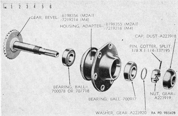
(2) Remove the dust cap and remove the cotter pin, gear nut, and washer from the bevel gear (fig. 107). If
924807°-51-11
158
Figure 105. Parts of hand elevating mechanism assembly.
necessary, use tubular wrench - 41-W-2940-8 (fig. 15) to remove gear nut.
(3) Remove the bevel gear from the adapter housing. The inner ball bearing may come out of the housing with the gear or it may remain in the housing (fig. 107).
(4) Remove the two ball bearings (fig. 107).
Figure 106. Power elevating mechanism.
159
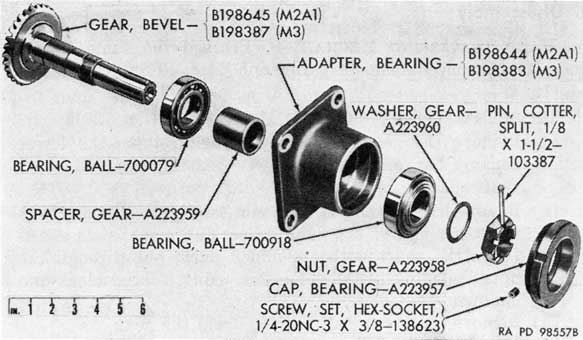
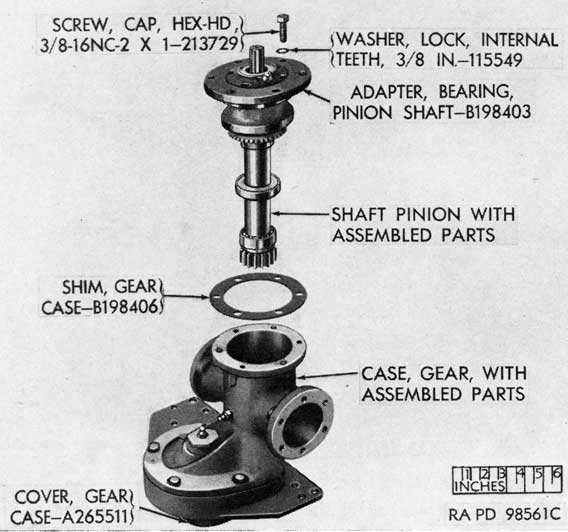
Figure 107. Parts of bearing adapter assembly.
c. WORM AND WORM WHEEL MECHANISM.
(1) Remove the worm wheel lower cover and gasket, after removing the retaining screws with lock washers. Clean out the case and the surface of the worm and worm wheel.
(2) Mark the worm and worm wheel to indicate their relative positions.
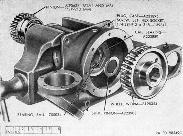
(3) Remove the cotter pin and nut from the pinion and remove the pinion from the case, using a suitable pusher or driving it out with a wood block and hammer (fig. 108).
(4) Remove the worm wheel and the shim from the gear case (fig. 109).
(5) Remove the case plug at the side of the case and through this opening remove the set screw which locks the bearing cap (fig. 108). Remove the bearing cap (fig. 109), using the bearing cap wrench - 41-W-1977-100 (fig. 14). Remove the bearing (fig. 109).
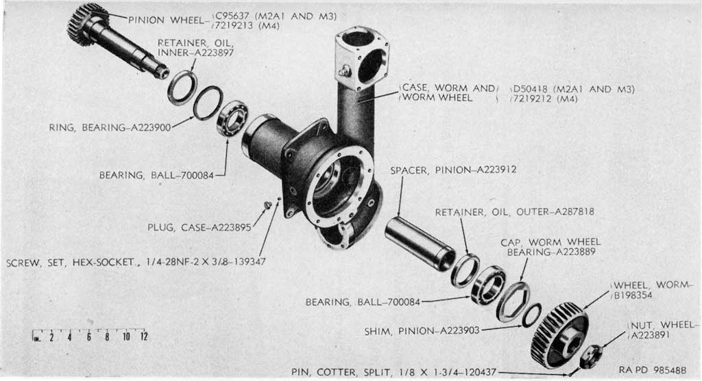
(6) Remove the outer oil retainer if it is to be replaced (fig. 109).
(7) Remove the pinion spacer from the pinion (fig. 109).
(8) Remove the ball bearing, the bearing ring, and the inner oil retainer from the pinion, if these parts are to be replaced (fig. 109). The bearing may have remained in
160
Figure 108. Removing pinion and worm wheel.
the case when the pinion was removed. If so, remove the bearing from the case.
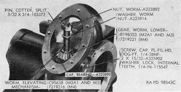
(9) Remove the cotter pin, worm nut, and worm nut washer from the lower end of the elevating mechanism worm and remove the lower gear and the shim (fig. 110). In the mount M3 there is no lower gear; a spacer-A338605 is used instead.
(10) Remove the upper cover from the gear case, after removing the retaining screws with lock washers.
(11) Remove the worm by forcing it out through the upper opening in the case (field maintenance method), or using an improvised gear pusher (figs. 20 and 111) (depot maintenance method). Remove the cotter pin, worm nut, and nut washer from the upper end of the worm and remove the upper gear, the upper gear shim, and the ball bearing from the worm (fig. 112).
(12) Remove the cap screw and remove the bearing cap (fig. 112), using the tubular wrench-41-W-3736-960 with wrench handle-41-H-1549-522 (fig. 14).
(13) Remove the worm bushing with double row ball bearing, the sleeve spacer, and the worm sleeve from the lower
161
Figure 109. Worm wheel and pinion parts.
162
Figure 110. Removing lower worm gear.
opening in the case (fig. 112). Remove the oil seal, if it is to be replaced.
73. Repair, Overhaul, and Rebuild
a. GENERAL.
(1) Clean all parts of the elevating mechanism and inspect for wear and damage and replace all parts that are
Figure 111. Removing the worm by means of a pusher.
163
Figure 112. Worm and worm parts.
164
obviously unfit for further service. Check parts (carriage M2A1) for surface treatment (par. 27).
(2) Check all gear shafts for straightness; shafts must be straight to operate satisfactorily.
b. HAND ELEVATING MECHANISM.
(1) Check all bearings for roughness, wear, and broken balls. Replace, if worn or broken.
(2) Check gears for burs, chips, and cracks. Remove minor abrasions from teeth and splines; replace, if chipped or cracked.
(3) Replace detent springs, if broken. Free height of spring should be 1 5/16 inches, solid height not more than 5/8 inch, and load of 2.16 pounds minimum at 29/32 inch.
(4) Repair damaged threads.
c. POWER ELEVATING MECHANISM (CARRIAGE M2A1).
(1) Check the ball bearings for rough spots, wear, and broken balls. Replace, if worn or broken.
(2) Check the bevel gear for burs, chips, and cracks. Remove minor abrasions from teeth and splines with a fine file and crocus cloth; replace, if chipped or cracked.
(3) Repair damaged threads.
d. WORM AND WORM WHEEL MECHANISM.
(1) Inspect the worm, worm gears, worm wheel, and pinion for burs, chips, cracks, and excessive wear. Remove minor abrasions; if teeth or threads are chipped or cracked, replace the part.
(2) Inspect oil retainers for damage and replace, if necessary.
(3) Check ball bearings for rough spots, wear, and broken balls. Replace, if damaged or worn.
(4) Repair damaged threads.
(5) Examine all bearing surfaces for burs and roughness; remove minor abrasions with a fine file and crocus cloth.
74. Assembly
a. WORM AND WORM WHEEL MECHANISM.
(1) The oil seal may be installed in the worm sleeve and the sleeve installed in the case before other parts are installed. In this method, the seal is installed with the spring side down. However, a more satisfactory seal can be provided if it is installed with the spring side uppermost. To do this, install the seal on the worm, using an improvised tapered sleeve similar to that shown in figure 20. Insert an improvised spacer about 3/32 inch thick
165
between the seal and the toothed portion of the worm. (This spacer will be removed after the worm has been installed.) Force the seal into position on the worm and remove the improvised sleeve.
(2) Install the double row ball bearing in the worm bushing (fig. 112) with the bearing numbers toward the outside or the thrust sides facing one another (fig. 112). If the bearings are assembled incorrectly, it will cause windup and backlash, particularly at low elevations where the torque is greater. If the numbers or thrust sides are not marked, assemble the bearings so that the flange sides on outer races face one another.
(3) If the oil seal was installed on the worm, install the worm sleeve in the case (fig. 112). Install sleeve spacer with beveled side down (fig. 112).
(4) Install worm bushing with bearings in lower end of case (fig. 112). Screw in bearing cap (fig. 112) with tubular wrench-41-W-3736-960 with wrench handle-41-H1549-522 (fig. 14). Lock bearing cap with lock washer and cap screw (fig. 112).
(5) Install bearing, upper gear shim, upper gear, nut washer, worm nut, and cotter pin on upper end of worm (fig. 112).
(6) Install the worm in the case, forcing it into position. If the oil seal was installed on the worm, remove the improvised spacer by withdrawing it through the worm wheel opening and tap the worm to seat it.
(7) Install the inner oil retainer ball bearing ring and the ball bearing on the wheel pinion (fig. 109).
(8) Install the. outer oil retainer and ball bearing in the case (fig. 109). Screw in cap (fig. 109) with the bearing cap wrench-41-W-1977-100 (fig. 14). Install the set screw and case plug to lock the bearing cap (fig. 109).
(9) Install the pinion spacer on the pinion and install the pinion in the case (fig. 109).
(10) Install the pinion shim and the worm wheel on the pinion (fig. 109), matching register marks on the worm and worm wheel.
(11) If a new worm wheel or worm is installed in the mechanism, it may be necessary to change the pinion shim back of the worm wheel or to fit the wheel to the worm by lapping.
(12) The worm wheel must be centered on the worm. Shims of varying thicknesses are provided to position the worm wheel. To select the correct shim proceed as follows:
166
Figure 113. Selecting correct thickness of pinion shim.
167
(a) Remove the pinion shim from back of the worm wheel and reassemble the worm wheel on the pinion.
(b) Push the worm wheel in as far as possible against the worm and, with a micrometer depth gage, measure the distance "A" from the cover mounting pad to the worm wheel (fig. 113). Then pull the worm wheel out and measure the distance "B" from the pad to the wheel (fig. 113). Add the two measurements and divide by two to obtain the mean dimension.
(c) Remove the worm and push the worm wheel in as far as it will go. Measure the distance "C" from the cover mounting pad to the wheel (fig. 113). The difference between this measurement and the mean dimension obtained in (b) above is the proper thickness for the shim to be installed.
(13) Tightness may be eliminated by lapping with fine lapping compound. Lap only around the high spots and, when these are eliminated, make two or three complete revolutions. After lapping, disassemble the parts and clean thoroughly to remove all traces of lapping compound.
(14) Install the wheel, worm wheel nut, and cotter pin (fig. 109).
(15) Install the lower worm gear, worm nut washer, worm nut, and cotter pin on the worm (fig. 112).
Note. For the mount M3, install the spacer-A338605 instead of the gear-B198353.
(16) Check the backlash between worm and worm wheel as follows:
(a) Lock the pinion by means of the pinion lock (fig. 18).
(b) Scribe a pencil mark on the central tooth of the worm wheel that fits completely into a notch in the worm.
(c) First twist the worm shaft one way until the slack is taken up, stop, and extend the mark onto the worm; then twist the shaft the other way until the slack is taken up, stop, and again extend the mark onto the worm.
(d) Measure the distance between the two marks. (Refer to par. 75 a.)
(17) Install the top cover gasket and top cover, the worm wheel cover with gasket, and the lower cover or covers with gaskets. Install cover retaining screws with lock washers.
b. POWER ELEVATING MECHANISM (CARRIAGE M2A1).
(1) Install the inner ball bearing-700078 or-707718 on
168
the bevel gear and install the gear in the housing (fig. 107).
(2) Install the outer ball bearing-700917 in the adapter housing, with the seal toward the outside (fig. 107).
(3) Install the gear washer and gear nut on the bevel gear and install the cotter pin (fig. 107). If necessary, use tubular wrench-41-W -2940-8 (fig. 15) to install gear nut.
(4) Install the dust cap over the end of the gear and into the housing (fig. 107).
(5) Install the bearing adapter assembly in position, with the adapter shim between the housing and the gear case (fig. 106). Install the six cap screws with lock washers. On the mount M3, install the gasket-A338603, the cover plate-A338604, and six cap screws-216971 and lock washers-115549 instead of the power elevating mechanism. Check for binding and eliminate by lapping (a (13) above).
(6) Check backlash between worm gear and wheel and between the adapter bevel gear and worm lower gear by either of the following methods:
(a) Lock the pinion. Install the output drive coupling on the splined shaft of the bearing adapter bevel gear. First twist the coupling one way until the slack is taken up, stop, and mark the adapter in line with the coupling. Then twist the coupling the other way until the slack is taken up, stop, and mark the adapter in line with the mark on the coupling. Measure the peripheral distance between the two marks on the adapter. (Refer to par. 75 a.)
(b) For an alternate method of checking backlash, using a backlash gage, refer to paragraph 194 a (2) (b) (depot maintenance only). Operations illustrated by figures 252 and 253 are also applicable to the elevating mechanism of carriage M2A1.
c. HAND ELEVATING MECHANISM.
(1) Install the inner ball bearing and gear spacer on the bevel gear and install the gear in the hand elevating housing (fig. 105).
(2) Install the outer ball bearing in the housing, with the oil seal toward the outside (fig. 105).
(3) Install the gear washer and gear nut on the bevel gear and install the cotter pin (fig. 105).
(4) Install the bearing cap (fig. 105), using the cap spanner
169
wrench-41-W-3250-242 (fig. 14). Aline the holes for the set screw and install the screw (fig. 105).
(5) Install the detent spring and two hand operating detents in the hand operating gear (fig. 104). Hold the detents against spring tension, while installing the gear in the hand operating sleeve. A narrow piece of stiff paper or thin metal banding may be used to hold the detents.
Note. The detents and spring are not used in the mechanism for the mount M3.
(6) Install the gear screw at the end of the gear and install the locking screw (fig. 104). On the mount M3, install the spacer. In some mechanisms, the screw-113626 and gear screw-A223966 are replaced by a cap screw -216971, internal teeth lock washer-111328, locking screw-132300, and gear washer-A287859 (fig. 250)
(7) Mount the hand elevating mechanism in position on the gear case, with the housing shim between the housing and the elevating case (fig. 103). Check for binding and eliminate by lapping (a (13) above).
(8) To measure backlash between worm gear and wheel and between worm upper gear and hand elevating bevel gear, proceed as follows:
(a) Lock the pinion.
(b) Twist the adapter one way until slack is taken up, stop, and mark the housing in line with the adapter.
(c) Twist the adapter the other way until slack is taken up, stop, and mark the housing in line with the mark on the adapter.
(d) Measure the peripheral distance between the two marks on the housing. (Refer to par. 75 a.)
75. Checks and Adjustments
a. BACKLASH.
(1) If total backlash is excessive (par. 12 d and e) , compare the backlash values for different points in the elevating mechanism as checked in paragraph 74 a (16), b (6), and c (8), in order to determine the extent and location of adjustment required.
(2) Backlash between the worm gear and wheel can be adjusted by changing the shim between worm gear and wheel (par. 74 a (12) ).
(3) Backlash between the worm upper gear and the hand elevating bevel gear can be adjusted by changing the shim between the gear case and the hand elevating housing.
170
(4) Backlash between the worm lower gear and the bearing adapter bevel gear can be adjusted by changing the shim between the gear case and the bearing adapter housing.
(5) Backlash at center or extremes of travel can be adjusted by changing shims between elevating gear sector and breech casing (par. 59 i).
(6) In adjusting the backlash between the gears, care must be taken not to create excessive binding. A few high spots can be eliminated by lapping around these spots and then making two or three complete revolutions. If binding is excessive, examine gears and replace, if worn or if shafts are not straight. Examine the pinion and elevating gear sector for wear as possible sources of backlash; replace if necessary. Refer also to paragraphs 59 i and 100 k for shimming the sector and top carriage trunnion bearing caps as means to reduce backlash between pinion and elevating gear sector.
b. TORQUE. If the torque values are in excess of those given in paragraph 12 c, proceed as follows:
(1) Check for binding between the pinion and elevating gear sector lap, if necessary, or change the gear sector shims (par. 59 i) or the bearing shims (par. 100 k).
(2) Lap the gears or change shims in elevating mechanism provided this does not create excessive backlash.
Section III. TRAVERSING MECHANISMS
76. General
a. This section covers the traversing mechanisms of the carriage M2A1 and mount M3 (figs. 114 and 115).
b. These mechanisms are similar except for the following:
(1) The traversing mechanism of the mount M3 is equipped for manual operation only; the gear case openings are closed by gaskets-A338601 and cover plate-A338602.
(2) The mechanism of the mount M3 does not have the pinion shaft bevel gear; instead the pinion shaft spacer-A338600 is used.
c. The instructions given herein pertain to both traversing mechanisms unless otherwise indicated.
171
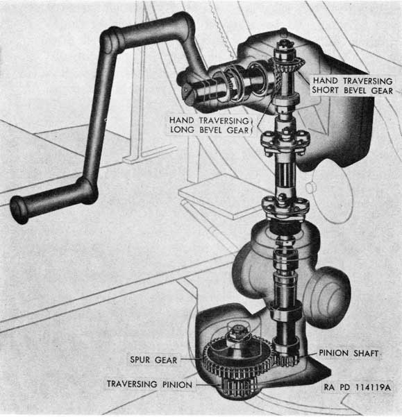
Figure 114. Phantom view of traversing mechanism in use with the carriage M2A1.
172
Figure 115. Phantom view of traversing mechanism in use with the mount M3.
77. Trouble Shooting
a. EXCESSIVE EFFORT NECESSARY TO TRAVERSE GUN. Difficulty in traversing the gun may be caused by worn or damaged pinion, spur gear, or bearings or lack of proper lubrication. Another possible cause for excessive effort in traversing the gun might be a tight or improperly installed dust seal. To correct, disassemble and replace worn or damaged parts (pars. 80 and 82). Refer to paragraph 97 for other causes of difficult traversing.
b. BINDING. Binding in the mechanism may be caused by incorrect meshing of the gears or by damaged gears or bearings. To correct, disassemble and replace defective parts (pars. 80 and 82). Install correct shims to provide proper meshing of gears (par. 83 a).
173
c. BACKLASH. Backlash in the traversing mechanism may be caused by incorrect meshing of the gears, worn or damaged gears, bearings, or pinion shaft, by incorrect positioning of the mechanism on the top carriage, or by loose retaining screws or taper pins securing the mechanism to the top carriage. Check total backlash (par. 13 d and e) before removing mechanism. Replace defective parts (pars. 80 and 82). Install correct shims to provide proper meshing of gears (par. 82). If the mechanism is loose, tighten the retaining screws and replace the taper pins. Refer to paragraph 83 a (2) for alining the mechanism to remove small amount of backlash between pinion and ring gear.
78. Removal
Note. Operations described in a below apply to carriage M2A1 only.
a. Disconnect oil gears as follows:
(1) Disconnect the tie bar (azimuth oil gear) from the hand traversing mechanism gear case.
(2) Disconnect the clutch operating rod from the slewing clutch lever (fig. 139).
(3) Disconnect the oil gear from the platform and move it forward to disengage it from the power traversing mechanism.
(4) Disconnect the flexible shaft of the computing sight from the deflection drive assembly; the drive assembly may be removed from the top of the traversing mechanism.
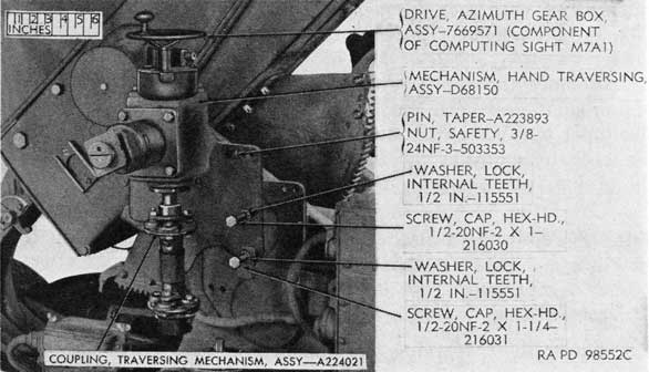
Figure 116. Hand traversing gear case mechanism and coupling removed.
924807 *-51-12
174
Figure 117. Traversing mechanism removed.
(5) Disconnect the oil gear from the platform frame and move it forward to disengage it from the power traversing mechanism.
b. Remove the traversing hand crank.
c. Loosen the cap screws that secure the hand traversing mechanism gear case to the top carriage and remove the two taper pins by tightening the safety nuts on the pins. Support the hand traversing mechanism gear case and remove the loose cap screws with lock washers completely. Lift the mechanism (fig. 116). Disconnect the coupling assembly from the shaft (fig. 118).
d. Remove the cap screws and lock washers that secure the pinion shaft gear case and parts to the top carriage; remove the two taper pins by tightening the safety nuts. Remove the traversing mechanism unit by carefully raising it straight up to disengage the pinion from the traversing ring gear (fig. 117).
e. Cover the opening in the top carriage with clean cloth or paper so that no dirt or other foreign matter will enter the opening.
79. Installation
a. Lower the traversing mechanism gear case with assembled parts into position on the top carriage, meshing the pinion with the ring gear and alining the holes for the cap screws and taper
175
pins (fig. 117). Be careful not to cause nicks in pinion and ring gear.
b. Install the cap screws with lock washers, but do not tighten the screws. Drive the taper pins into place and tighten the screws. Be sure that the safety nuts are on the taper pins (fig. 117).
c. Place the hand traversing mechanism and coupling assembly in position over the traversing mechanism, with the coupling assembly engaging the upper end of the pinion shaft and the lower end of the hand traversing mechanism shaft and the screw holes in the gear case alined with those in the top carriage (fig. 116).
d. Install the cap screws with lock washers and tighten lightly. Drive in the two taper pins and tighten the cap screws. Be sure that the safety nuts are on the taper pins (fig. 116).
e. Install the traversing hand crank.
f. In the case of the carriage M2A1, proceed as follows:
(1) Push the oil gear back so that oil gear coupling engages the splined shaft of the bevel gear in the bearing adapter assembly.
(2) Secure oil gear to the platform.
(3) Secure clutch operating rod to the clutch lever. Check alinement of oil gear with a coupling gage (TM 9-252).
(4) Secure the tie bar (azimuth oil gear) to hand traversing mechanism gear case.
(5) Replace the deflection drive assembly and connect the flexible shaft of the computing sight.
80. Disassembly
a. HAND TRAVERSING MECHANISM. Proceed the same as for hand elevating mechanism in paragraph 72 a. Refer to figs. 118 and 119.
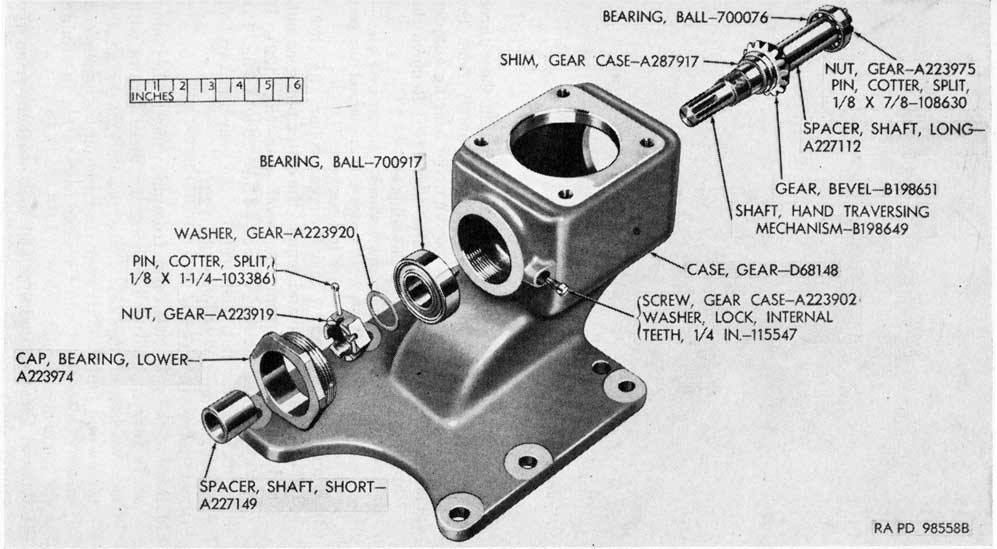
b. HAND TRAVERSING GEAR CASE MECHANISM (fig. 120).
(1) Remove the gear case screw which retains the lower bearing cap and remove lower bearing cap and short shaft spacer.
(2) Remove the cotter pin, gear nut, and gear washer from the lower end of the hand traversing mechanism shaft.
(3) Drive the shaft with assembled parts out through the upper opening in the gear case, using a wood block and hammer.
(4) Remove the lower ball bearing from the gear case.
(5) Remove the cotter pin, gear nut, and gear washer from the upper end of the shaft.
176
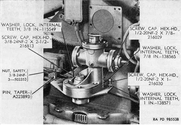
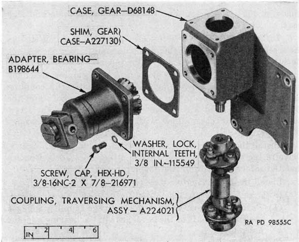
Figure 118. Hand traversing mechanism, coupling, and gear case.
(6) Remove the ball bearing, long shaft spacer, bevel gear, and gear case shim from the shaft.
c. POWER TRAVERSING MECHANISM (CARRIAGE M2A1).
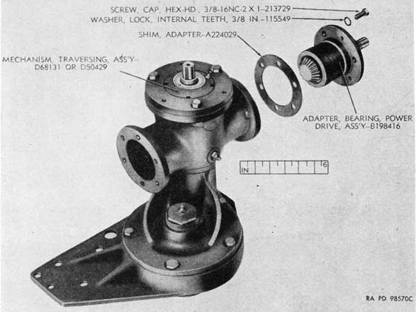
(1) Remove the three cap screws with lock washers. Then install a 3/8-24NF pusher screw in each of the three
Figure 119. Parts of hand traversing mechanism.
177
Figure 120. Part of hand traversing mechanism gear case (carriage M2A1).
178
Figure 121. Power drive adapter and traversing mechanism.
alternate blind holes in the adapter, tighten these three screws evenly to push the adapter assembly from the gear case, and remove the power drive bearing adapter assembly and the adapter shim (fig. 121). Remove the three pusher screws from the adapter.
Note. The traversing mechanism for the mount M3 has a cover plate-A338602 and a gasket-A338601 attached to each side opening of the gear case by means of the screws-216971 and lock washers-115549.
(2) Remove the set screw and the gear collar (fig. 122). Remove the dust cap and remove the cotter pin, gear nut, and gear washer from the bevel gear (fig. 122). If necessary, use tubular wrench-41-W-2940-8 (fig. 15) to remove gear nut. Then remove the gear and two ball bearings from the adapter (fig. 122).
d. PINION SHAFT MECHANISM.
(1) Remove the gear case cover from underneath the pinion shaft gear case, after removing the three screws with lock washers (fig. 125). Place register marks on the pinion and pinion shaft gear case and on the upper end of the pinion shaft and the gear case to aid in alining the parts at assembly.
(2) Remove three cap screws and lock washers from the pinion shaft bearing adapter (fig. 123). Using three
179
Figure 122. Parts of traversing mechanism power drive adapter assembly.
pusher screws in the smaller holes in the adapter, remove the adapter with assembled parts from the gear case and remove the shim (fig. 123).
(3) Remove the lubricating fitting and the set screw from the pinion bearing cap (fig. 124).
(4) Remove the bearing cap (fig. 124), using the tubular wrench-41-W-3736-960 (fig. 14) with wrench handle -41-H-1549-522. The oil retainer may be removed from the pinion shaft bearing cap (fig. 124), if necessary.
(5) Remove the short spacer, the cotter pin, and pinion shaft nut from the upper end of the pinion shaft (fig. 124). Remove the small spacer and drive or press the pinion shaft out of the adapter (fig. 124).
(6) Remove the pinion shaft bevel gear (fig. 124) (in mount M3 a spacer-A338600 is used instead of bevel gear). Remove the oil seal, the long spacer, and the lower ball bearing from the pinion shaft (fig. 124). In mechanisms of alternate design, an oil deflector and an oil trap are used in place of the oil seal.
(7) Remove the double row ball bearing from the bearing adapter (fig. 124).
180
Figure 123. Pinion shaft mechanism removed from gear case.
e. PINION AND SPUR GEAR.
(1) Remove the set screw that locks the gear bearing cap and remove cap from the traversing gear case (fig. 125). Remove the cotter pin, gear nut, and gear washer from the upper end of the traversing mechanism pinion (fig. 125). Drive the pinion part way out of the case.
(2) Remove the gear case bolt and safety nut and cap screws with lock washers and separate the two gear cases (fig. 125).
(3) Mark the position of the spur gear on the pinion and drive the pinion the rest of the way out of the case. Remove the lower ball bearing from the pinion (fig. 125).
(4) Remove the spur gear from the pinion shaft gear case (fig. 125). Also remove the upper ball bearing from the gear case (fig. 125).
181
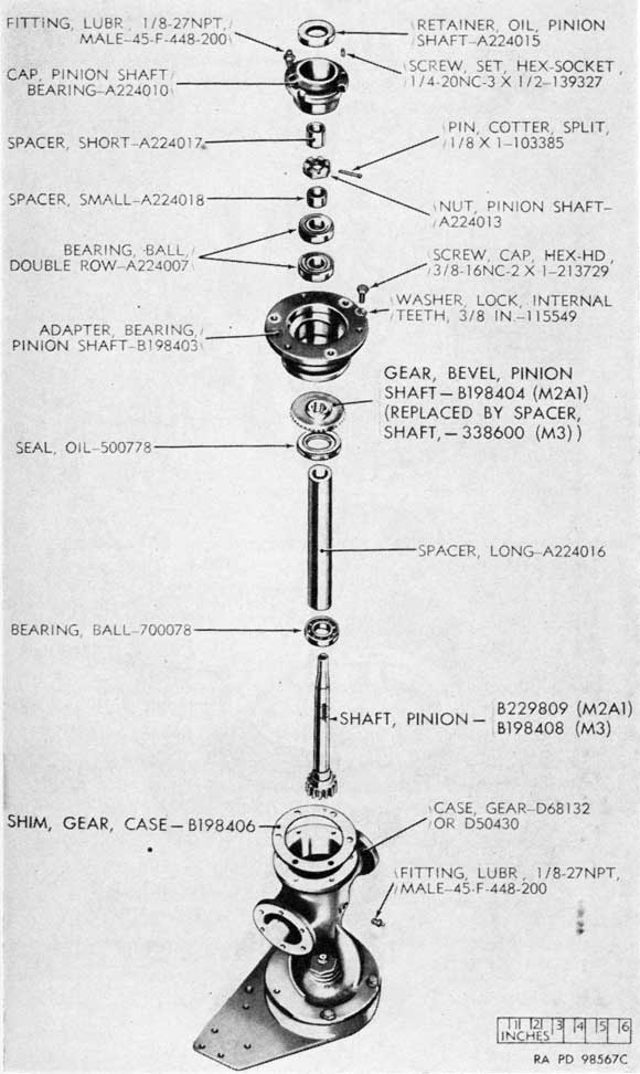
Figure 124. Parts of pinion shaft mechanism.
182
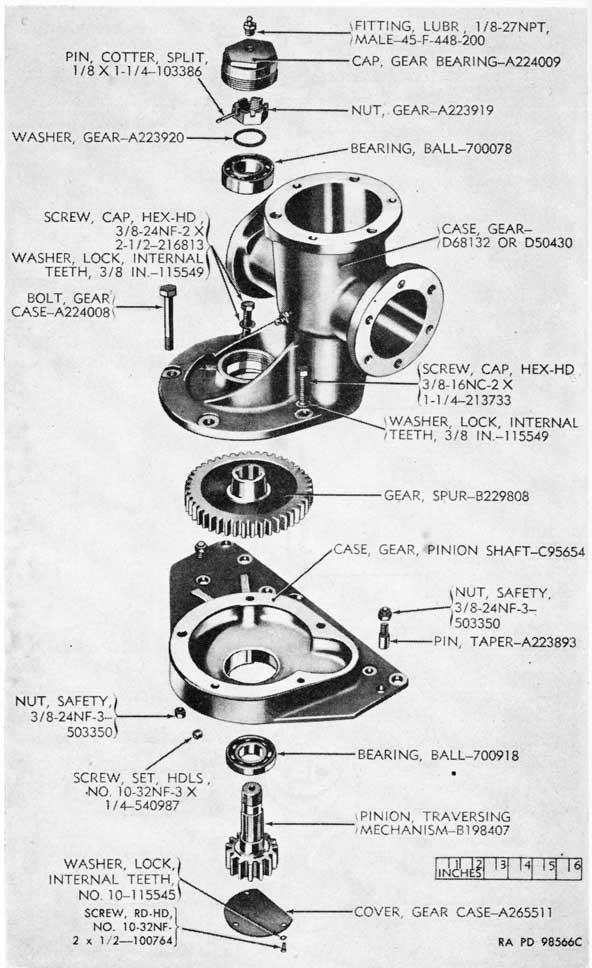
Figure 125. Parts of pinion, spur gear, and cases.
183
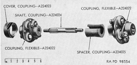
Figure 126. Parts of coupling assembly.
f. COUPLING ASSEMBLY.
(1) Remove the two flexible couplings from the shaft (fig. 126). Remove the coupling cover from the lower coupling (fig. 126), if it is to be replaced.
(2) Remove the coupling spacer from the coupling shaft (fig. 126).
Note. Some traversing mechanisms are equipped with coupling assemblies -6198648 of different design; these have no shaft, spacer, or cover.
81. Repair, Overhaul, and Rebuild
a. GENERAL.
(1) Clean all parts of the traversing mechanism, inspect for wear and damage, and replace all parts that are obviously unfit for further service. Check parts (carriage M2A1) for surface treatment (par. 27).
(2) Check all gear shafts for straightness; shafts must be straight to operate satisfactorily.
b. HAND TRAVERSING AND GEAR CASE MECHANISMS.
(1) Check all bearings for roughness, wear, and broken balls. Replace, if worn or broken.
(2) Check gears for burs, chips, and cracks. Remove minor abrasions from teeth and splines; replace, if chipped or cracked.
(3) Repair damaged threads.
c. POWER TRAVERSING MECHANISM.
(1) Check the ball bearings for rough spots, wear, and broken balls. Replace, if worn or broken.
(2) Check the bevel gear for burs, chips, and cracks. Remove
184
minor abrasions from teeth and splines; replace, if chipped or cracked.
(3) Repair damaged threads.
d. SHAFT AND PINION GROUP.
(1) Inspect the gears and pillion for burs, chips, cracks, and wear. Remove minor abrasions; if teeth of spur gears are chipped or cracked, they must be replaced.
(2) Inspect oil retainers for damage and replace, if necessary.
(3) Check ball bearings for rough spots, wear, and broken balls. Replace, if damaged or worn.
(4) Repair damaged threads.
(5) Examine all bearing surfaces for burs and roughness; remove minor abrasions.
82. Assembly
a. COUPLING ASSEMBLY.
(1) Install the coupling spacer on the shaft and install the two flexible couplings, one at each end of the shaft (fig. 126).
(2) Install the coupling cover over the end of the lower coupling (fig. 126).
b. PINION AND SPUR GEAR.
(1) Install the lower ball bearing on the pinion with the seal down and install the pinion in position in the pinion shaft gear case (fig. 125).
(2) Install the spur gear on the pinion, matching reference marks on the splines and spline ways (fig. 125). Be sure that the longer portion of the gear hub faces upward.
(3) Install the upper ball bearing in the traversing gear case and assemble the two gear cases with cap screws, lock washers, and gear case bolt with safety nut (fig. 125).
(4) Install the gear washer, gear nut, and cotter pin on the upper end of the pinion (fig. 125).
(5) Install the gear bearing cap in the traversing gear case, aline the set screw openings, and install the set screw (fig. 125).
c. PINION SHAFT MECHANISM.
(1) Install the lower ball bearing and the long spacer on the pinion shaft (fig. 124). Install the oil seal, with the spring side facing upward. Then tap the pinion shaft bevel gear into position on the shaft (fig. 124). If the mechanism is of alternate design, install the oil trap and deflector before installing the bevel gear.
185
(2) Install the double row ball bearings in the pinion shaft bearing adapter, with the seals toward the outside (fig. 124).
(3) Install the pinion shaft with assembled parts in the adapter and install the small spacer, the pinion shaft nut, and cotter pin on the shaft; install the short spacer (fig. 124).
(4) If the oil retainer was removed from the pinion shaft bearing cap, install the new retainer, with the spring facing upward (fig. 124). Screw the bearing cap to the adapter (fig. 124), using the tubular wrench-41-W3736-960 (fig. 14) and wrench handle-41-H-1549-522. Aline the set screw openings and install the set screw (fig. 124). Install the lubricating fitting in the cap (fig. 124).
(5) Install the gear case shim on the traversing gear case and install the pinion shaft with assembled parts in the gear case (fig. 123). Match reference marks on the pinion shaft and the gear case and those on the pinion and pinion shaft gear case. Install the cap screws with lock washers on the bearing adapter (fig. 123), tightening the screws evenly to force the parts into the case.
(6) Install the gear case cover with screws and lock washers to bottom of pinion shaft gear case.
(7) Turn pinion shaft and test for binding.
(8) Check backlash as follows:
(a) Lock the pinion.
(b) Twist pinion shaft one way until slack is taken up, stop, and mark the shaft in line with the adapter. Twist the shaft the other way until the slack is taken up, stop, and mark the adapter in line with the mark on the shaft.
(c) Measure the peripheral distance between the two marks on the adapter. (Refer to par 83 a.)
d. POWER TRAVERSING MECHANISM.
(1) Install the inner ball bearing on the bevel gear and install the outer ball bearing in the adapter (fig. 122). Be sure the metal seals of the bearings are toward the outside of the adapter.
(2) Install the bevel gear in the bearing adapter (fig. 122).
(3) Install the gear washer, gear nut, and cotter pin on the bevel gear (fig. 122). If necessary, use tubular wrench-41-W-2940-8 (fig. 15) to install gear nut.
(4) Install the dust cap (fig. 122).
(5) Install the gear collar and set screw (fig. 122).
186
Figure 127. Parts of hand traversing mechanism gear case of mount M3.
187
(6) Install the adapter shims for the power drive bearing adapter assembly and install the assembly in the gear case (fig. 121). It may be necessary to turn the bevel gears back and forth to engage the bevel gear on the pinion shaft.
(7) Install the three cap screws with lock washers for the adapter assembly (fig. 121). (On the mount M3, install the two cover plates with gaskets.)
(8) Turn the bevel gears and the pinion shaft by hand and test for binding. Eliminate binding by lapping as described in paragraph 74 a (13).
(9) Check the backlash between the pinion shaft and spur gear and between the power drive bevel gear and pinion shaft bevel gear, using the method described in paragraph 74 b (6). Refer to paragraph 83 a.
e. HAND TRAVERSING GEAR CASE MECHANISM (fig. 120).
(1) Install the gear case shim, bevel gear, long shaft spacer, and upper ball bearing on the hand traversing mechanism shaft. Install the gear washer, gear nut, and cotter pin on the upper end of the shaft. The bevel gear in mount M3 is installed with the teeth down; refer to figure 127 for arrangement of parts in gear case of mount M3.
(2) Install the lower ball bearing in the gear case, with the seal toward the bottom. Be careful not to damage the seal.
(3) Install the shaft with assembled parts through the upper opening in the case and tap it into position.
(4) Install the gear washer, gear nut, and cotter pin on the lower end of the shaft.
(5) Install the lower bearing cap in the gear case, aline the holes for the gear case screw, and install the screw.
(6) Install the short shaft spacer on the shaft.
f. HAND TRAVERSING MECHANISM.
(1) Proceed the same as for the hand elevating mechanism in paragraph 74 c. Refer to figures 118 and 119.
(2) To check backlash between the hand traversing bevel gear and the hand traversing short bevel gear, lock the hand traversing shaft, twist the adapter one way until slack is taken up, stop, and mark the adapter and housing in line; then twist the adapter the other way until slack is taken up, stop, and mark the housing in line with the mark on the adapter; measure the peripheral distance between the two marks on the housing. (Refer to par. 83a.)
188
83. Checks and Adjustments
a. BACKLASH.
(1) If total backlash is excessive (par. 13 d and e), compare the backlash values for different points obtained in the traversing mechanism, as checked in paragraph 82 c (8), d (9), and f (2) , in order to determine the extent and location of the adjustment required. Also examine the pinion and traversing ring gear for wear as possible sources of backlash.
(2) A small amount of backlash may be eliminated by moving the traversing mechanism a slight amount and reaming the taper pin holes to hold the assembly in the new position. Before the taper pin holes are reamed, the precautions outlined below must be taken to prevent the chips from falling into the bearing or the entire top carriage must be removed and the bearing disassembled to clean out the chips:
(a) Remove the six cap screws from the inspection hole cover and remove the cover and gasket. Grease both sides of a 3 X 6-inch piece of flat paper and place it on the ring gear.
(b) Mark the frame at each end of the paper with chalk or pencil. Traverse the carriage back and forth and note if the paper has moved.
(c) Traverse the carriage to bring the dowel pin hole to be reamed directly over the paper (between the two marks on the frame).
(d) Remove the two taper pins by tightening the taper pin nuts. Loosen the assembly retaining screws just enough to move the assembly by tapping. Tap the assembly into the position where backlash is eliminated and the gears are not binding. Tighten the retaining screws and ream the taper pin holes. Install oversize taper pins. Be sure the safety nuts are installed on the pins.
(e) Traverse the carriage back to the position where the paper was installed and carefully remove it. All of the reamer chips should be in the grease.
(f) Install the gasket, inspection cover, screws, and washers.
(g) Traverse the gun through full range to see that no interference occurs.
(3) To reduce backlash between the pinion shaft and spur gear, replace worn gears.
189
(4) Backlash between pinion shaft bevel gear and power drive bevel gear can be reduced by changing the shim between the adapter and the case.
(5) Backlash between the hand traversing short and long bevel gears can be reduced by changing the shim between the adapter and the case.
(6) In adjusting backlash between the gears, care must be taken not to create excessive binding. A few high spots can be eliminated by lapping. If binding is excessive, examine gears and replace, if worn or if shafts are not straight.
b. TORQUE. If torque value is excessive (par. 13 c), proceed as follows:
(1) Check for binding between the pinion and the traversing ring gear and lap, if necessary.
(2) Lap gears or change shims in traversing mechanism provided this does create excessive backlash.
Section IV. TOP CARRIAGE FIRING LINKAGE
84. General
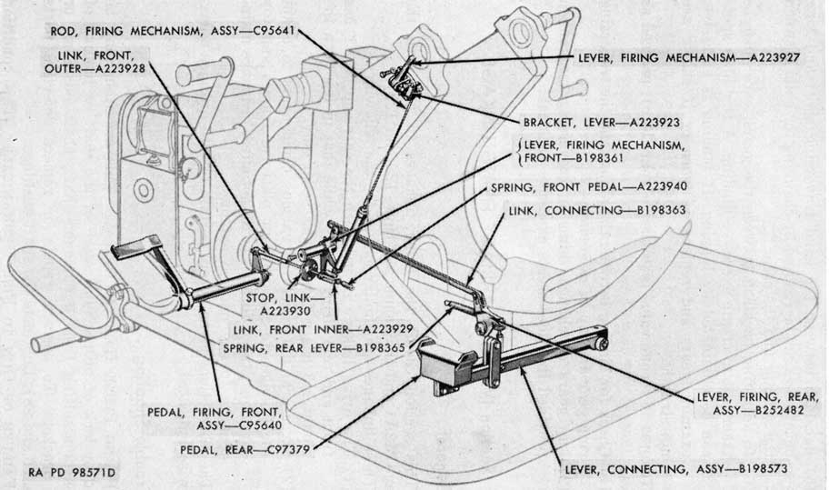
a. This section covers the firing linkages in use with the carriage M2A1 and the mount M3 (figs. 128 and 129).
b. These linkages are similar except for the following:
(1) The firing linkage in use with the carriage M2A1 has front and rear firing pedals while that in use with the mount M3 has a front firing pedal only.
(2) Structural differences of various components to adapt the linkages to the different platform frames and top carriages; these differences do not affect ordnance maintenance to any marked extent.
c. The instructions given herein pertain to both linkages unless otherwise indicated.
85. Trouble Shooting
a. FIRING PEDAL HARD TO OPERATE. This condition may be caused by lack of proper lubrication of the shaft or binding of the parts resulting from a damaged shaft, shaft bushings, or loose brackets. To correct, repair or replace defective parts (pars. 86 and 88). Lubricate the shaft bushings.
b. FAILURE OF GUN TO FIRE MECHANICALLY. This condition may be caused by incorrect adjustment, weak or broken springs, damaged firing mechanism rod assembly, or missing, worn, or
924807°-61-18
190
Figure 128. Phantom view of firing linkage of carriage M2A1.
191
Figure 129. Phantom view of firing linkage of mount M3.
192
damaged connecting pins in the linkage. Replace broken, worn,
or missing parts (pars. 86 and 88). Adjust the linkage (par. 89).
c. EXCESSIVE FREE PLAY. Excessive free play in the firing linkage may be caused by worn or damaged bushings, loose retaining parts, or incorrect adjustment of linkage. To correct this condition, adjust the linkage (par. 89), replace worn or damaged bushings, and tighten all retaining parts (pars. 86 and 88).
86. Disassembly
Note. It is seldom necessary to disassemble the complete firing linkage and good judgment will be exercised to reduce disassembly operations to a minimum.
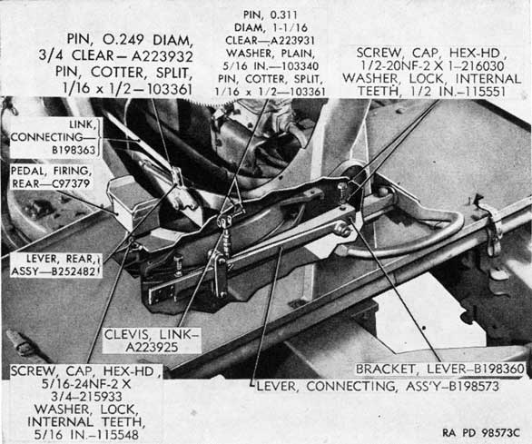
a. REAR FIRING PEDAL MECHANISM (CARRIAGE M2A1).
(1) Detach the rear firing pedal from the connecting lever by removing the screws and lock washers (fig. 130).
(2) Detach connecting link by removing cotter pin, washer, and rod end pin at front lever (fig. 131) and cotter pin and pin at rear lever (fig. 130).
(3) Detach link clevis from rear lever by removing cotter pin, washer, and pin (fig. 132).
Figure 130. Disassembly of rear firing pedal mechanism.
193
Figure 131. Disassembly of firing linkage at front end.
(4) Remove rear lever assembly (fig. 135) from left stay and left support angle (fig. 137) by removing cotter pins, washer, nut, and rear lever pin.
(5) Remove the two cap screws and lock washers that secure the lever bracket to the top carriage (fig. 132); remove the lever bracket with attached parts and disassemble (fig. 132).
b. FRONT FIRING PEDAL MECHANISM.
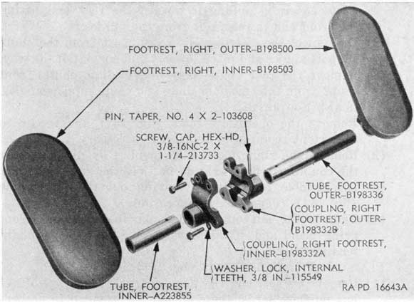
(1) Remove the left footguard. Remove the outer left footrest assembly from the inner left footrest assembly by removing the cap screws and lock washers that hold the inner and outer couplings together (fig. 133). Do not lose the key (fig. 133).
(2) Detach the front firing pedal with inner left footrest from the outer front link by removing cotter pin, washer, and rod end pin (fig. 133).
(3) Drive out the taper pin from the footrest shaft collar and separate the footrest and firing pedal assemblies (fig. 134); remove the two bushings from the pedal assembly, if necessary, drive out taper pin and disassemble the outer footrest assembly (fig. 134) (depot maintenance only).
194
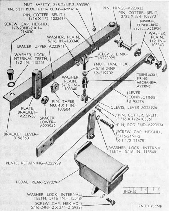
Figure 132. Parts of rear firing pedal mechanism.
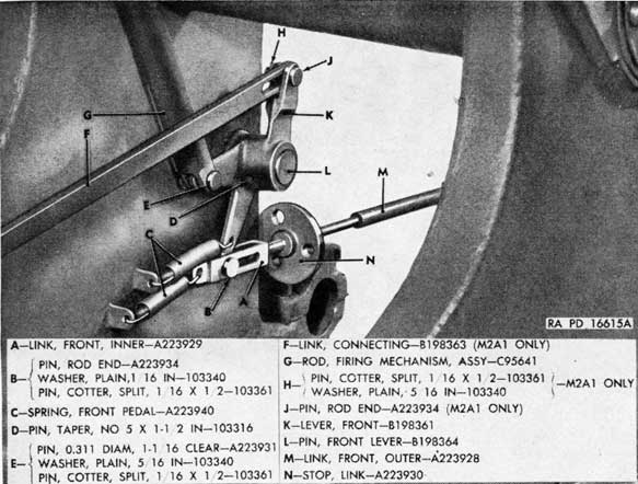
c. FIRING MECHANISM ROD AND LINKAGE.
(1) Disconnect the firing mechanism rod assembly from the firing mechanism lever by removing the cotter pin, washer, and clevis pin (figs. 131 and 135).
(2) Disconnect the lever bracket from the top carriage and remove the firing mechanism lever and bracket (fig. 135).
(3) Remove the cartridge ejector chute cover (par. 91 c (1)) and disconnect the front links and the firing
195
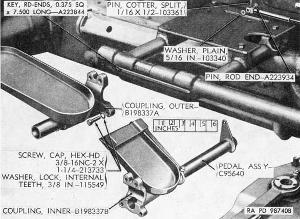
Figure 133. Outer and inner left footrest and front firing pedal assemblies.
mechanism rod assembly by removing the cotter pins, washers, and pins (figs. 131 and 135).
(4) Drive out the taper pin that secures the front lever to the front lever pin and remove front lever and lever pin (figs. 131 and 135).
(5) Drive out the straight pin that secures the rod coupling to the clevis rod and remove the clevis rod (fig. 136). Turn the rod coupling up against the casing bushing and unscrew casing bushing with rod coupling, rod spring, and firing rod as a unit from rod casing. Place the rod with assembled parts in an arbor press, compress the rod spring, unscrew the rod coupling, carefully release spring pressure, and remove parts (fig. 136).
87. Repair, Overhaul, and Rebuild
a. Clean all parts and examine for wear and damage. Check parts (carriage M2A1) for surface treatment (par. 27).
b. Check all weldments for breaks or incipient cracks. Repair, if practicable; if not, replace.
c. Check movement of pedal shaft in tube; there should be no binding. If necessary, dress surface of shaft.
196
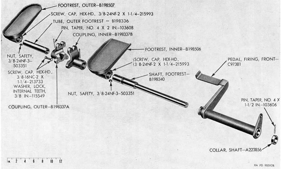
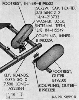
Figure 134. Parts of footrest and front firing pedal assemblies.
197
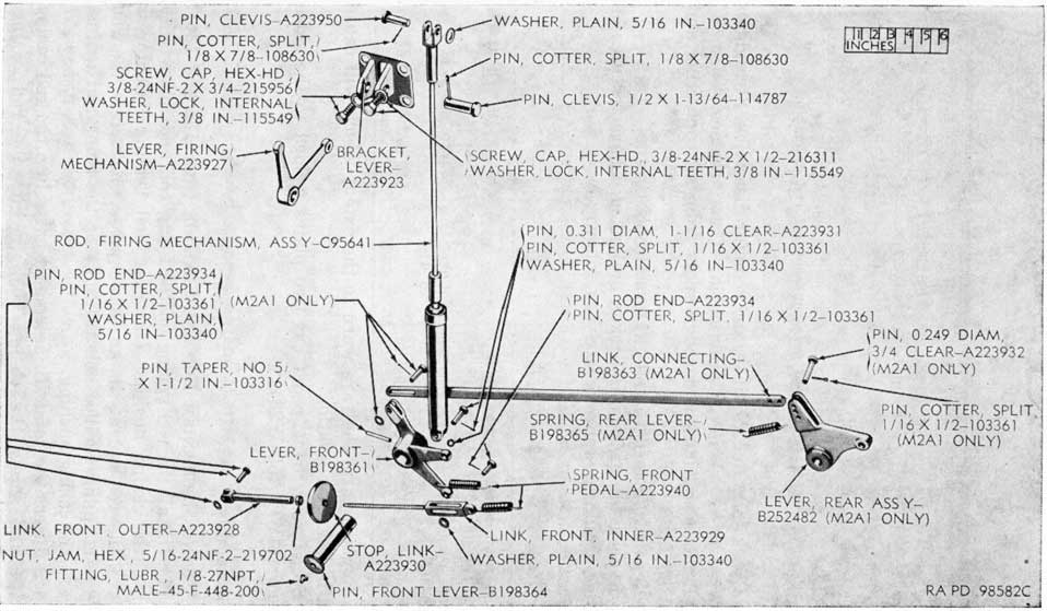
Figure 135. Components of firing mechanism rod and linkage.
198
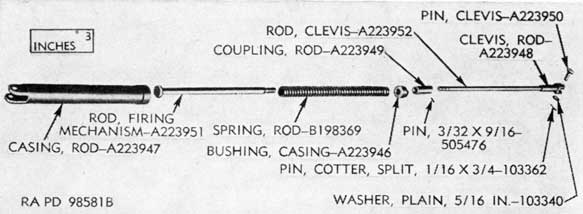
Figure 136. Parts of firing mechanism rod assembly.
d. Check shaft, levers, links, and rods for distortion. Straighten distorted parts whenever practicable; if not, replace.
e. Remove any burs and rough spots from all contacting and pivot surfaces.
f. Repair damaged threads, if practicable.
g. Replace all springs, if broken or kinked. Characteristics of springs should be approximately as follows:
Spring
Approximate free height
Solid height
Load
Spring, front pedal-A223940.
2 to 3 1/16 in.
15 1/2 to 19 1/2 lb at 5 3/4 in.
Spring, rear lever-B198365.
Not over 4 7/16 to 4 1/2 in.
28.5 to 31.5 lb at 5 11/16 in.
Spring, rod-B198369
9 1/4 to 9 3/4 in.
209 to 297 lb at 6 1/8 in.
h. Replace parts that are worn to the extent which will cause slack in linkage operation.
i. See if rear firing pedal has two plates welded to the sides thereof (MWO A50-W23).
88. Assembly
a. FIRING MECHANISM ROD AND LINKAGE (figs. 135 and 136).
(1) Install the rod spring on the firing rod and follow with the casing bushing (threaded end leading). Compress the rod spring in an arbor press and screw the rod coupling (drilled hole trailing) on the firing rod against the casing bushing.
(2) Insert the rod with assembled parts into the rod casing and screw the casing bushing into the rod casing. Unscrew the rod coupling one or two turns to provide room for adjustment.
199
(3) Screw clevis rod into the rod coupling, aline holes for taper pin, and drive in taper pin. Screw the rod clevis onto the clevis rod.
(4) Install the firing rod assembly, engaging the linkage at upper and lower ends. Connect all the links and pins.
b. FRONT FIRING PEDAL MECHANISM.
(1) Replace the two bushings in the front pedal assembly, if they had been removed.
(2) Assemble and install the left inner footrest assembly to the pedal assembly and secure by replacing shaft collar and taper pin (fig. 134). Attach the unit to the outer link by means of the rod end pin, washer, and cotter pin (fig. 134).
(3) Assemble and connect the left outer footrest assembly to the left inner footrest by means of the cap screws, lock washers, and key (fig. 133). Install left footguard.
c. REAR FIRING. PEDAL MECHANISM (CARRIAGE M2A1).
(1) Assemble the parts of the rear firing pedal mechanism that are secured to the top carriage under the platform (fig. 132); secure the lever bracket to the top carriage by means of the two cap screws and lock washers (fig. 132).
(2) Install the rear lever (fig. 135) and secure to left stay and left support angle (fig. 137).
(3) Attach the connecting link to front and rear levers (figs. 130 and 131). Secure the upper link clevis to the rear lever by means of the pin, washer, and cotter pin (fig. 132).
(4) Secure the rear firing pedal to the connecting lever by means of the four cap screws and lock washers (fig. 130).
89. Checks and Adjustment of Top Carriage Firing Linkage.
a. Loosen the jam nut. Turn the firing lever stop on the link until light contact is obtained between the firing lever and the firing plunger.
b. If the proper adjustment cannot be obtained by above method, disconnect the rod clevis from the firing lever and adjust the rod to give the proper action.
c. To check and adjust front and rear firing pedals, refer to TM 9-252. Front firing pedal should clear right footrest by at least three-fourths inch when fully depressed; if not, move footrest to give this clearance.
200
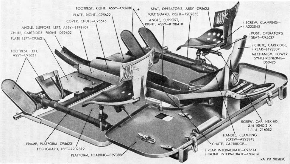
Figure 137. Frame platform group of carriage M2A1.
201
Section V. FRAME PLATFORM GROUPS
90. General
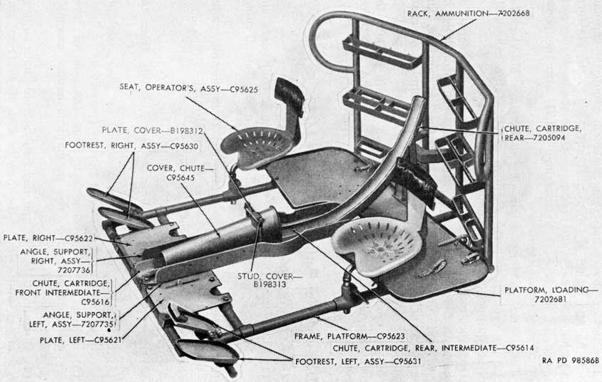
a. This section covers the frame platform groups of the carriage M2A1 and mount M3 (figs. 137 and 138). Each platform group includes the cartridge chutes, seats, footrests, frame platform, and, in the case of the carriage M2A1, also the power synchronizing mechanism.
b. The frame platform group of the carriage M2A1 differ structurally from the frame platform group of the mount M3 which is equipped with an ammunition rack.
c. Ordnance maintenance of the platforms consists of repair or replacement of worn or damaged parts. This can, ordinarily, be done without removing the frames from the top carriage. The frame platform is seldom removed except for complete overhaul of the materiel.
d. The instructions given in this section pertain to both the platform groups of the carriage M2A1 and mount M3, unless otherwise indicated.
91. Disassembly of Platform of Carriage M2A1
a. GUN AND CONTROL SYSTEM.
(1) Disconnect the cables from all switches, oil gears and motors, contact ring, and distribution box. Tag all cables to insure correct replacement.
(2) Disconnect clutch operating rod from slewing clutch lever and remove oil gears (TM 9-1678).
(3) Remove breech casing (par. 55).
b. POWER SYNCHRONIZING MECHANISM.
(1) Remove the azimuth limit switch assembly from the switch bracket (fig. 139).
(2) Detach the connecting link and rear lever assembly from rear firing pedal mechanism (par. 86 a).
(3) Detach the connecting bar from the control lever assembly and from the mechanism handle assembly (fig. 139).
(4) Disconnect the left and right stays from chute support angles and remove the handle and stays from stay spindle (fig. 140). Disassemble the handle and stay assemblies (fig. 140) (depot maintenance only).
(5) Disconnect clutch operating rod from the slewing clutch lever (fig. 139).
202
Figure 138. Frame platform group of mount M3.
203
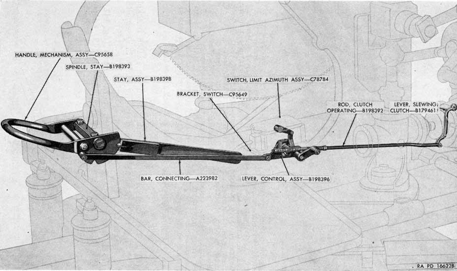
Figure 139. Disassembly of power synchronizing mechanism.
(6) Detach control lever assembly from the switch bracket (fig. 139). Separate clutch operating rod with assembled parts from the control lever assembly (fig. 139).
(7) Disassemble parts from clutch operating rod (fig. 141).
(8) Disassemble the control lever assembly (fig. 142) (depot maintenance only).
Figure 141. Parts removed from clutch operating rod.
205
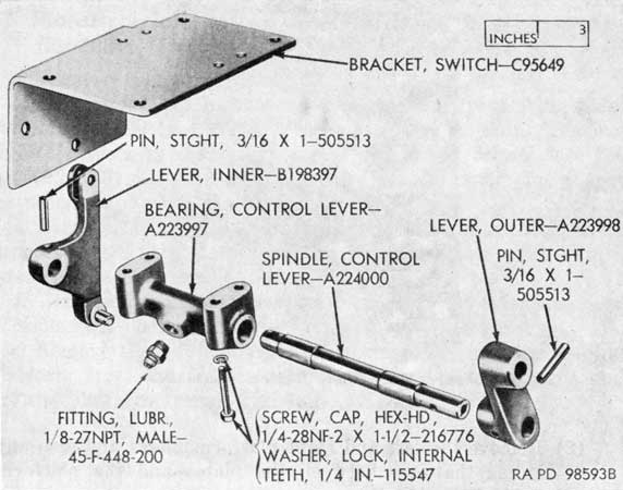
Figure 142. Parts of control lever assembly.
c. CARTRIDGE CHUTES (fig. 137).
(1) Remove the two studs and locking plate and remove the chute cover by pulling it toward the rear and lifting the front end to release it from the pintles.
(2) Disconnect the distribution box support from the chute support angles and place support and box out of the way.
(3) Remove the rear chute, rear intermediate chute, front chute, front intermediate chute and chute support angles.
d. SEATS AND FOOTRESTS.
(1) Remove the operators' seats (fig. 137) and repair to the extent required or replace, if necessary.
(2) Remove the right footrest assemblies by disconnecting the couplings (fig. 143); do not lose the key (fig. 143).
(3) Disassemble footrests by driving out the taper pins (fig. 144) (depot maintenance only).
(4) Remove the left outer and inner footrests and front firing pedal and disassemble (par. 86 b) (depot maintenance only).
e. PLATFORM FRAME ASSEMBLY (fig. 137).
(1) Remove the left and right footguards. If carriage M2A1 has no footguards, these should be provided in accordance with MWO A50-W23.
924807.-51-14
206
Figure 143. Right footrest assemblies.
(2) Remove the left and right platform plates and also any shims that are between the plates and the platform frame. Tag the shims.
(3) Remove the loading platform from the platform frame.
(4) Remove the two platform caps and lift the platform frame.
Figure 144. Parts of right footrest assemblies.
207
92. Disassembly of Platform of Mount M3 (fig. 138)
a. Remove the breech casing (par. 55).
b. Remove left outer and inner footrests and front firing pedal and disassemble (par. 86 b) (depot maintenance only). Remove right footrests by disconnecting the couplings; do not lose the key (fig. 143). Disassemble by driving out the taper pins (depot maintenance only).
c. Remove the two cover studs, cover plate, chute cover, chute support angles, the rear chute, rear intermediate chute, front intermediate chute, and deflector.
d. Remove the operators' seats and repair to the extent required or replace, if necessary.
e. Remove the left and right platform plates and the loading platform from the frame; remove the two platform caps and lift the platform frame (fig. 138).
93. Repair, Overhaul, and Rebuild
a. Examine all parts of the platform, including the retaining components for accessories and equipment, for cracks and breaks. If practicable, repair by welding; if not, replace. Check parts (carriage M2A1) for surface treatment (par. 27).
b. Check the cartridge chute components for deformations. If practicable, restore to correct shape; badly damaged parts should be replaced.
c. Clean all parts of the power synchronizing mechanism of the carriage M2A1. Examine all parts for burs and rough spots, particularly on contacting surfaces, and remove. Check clutch operating rod for straightness; if deformed, replace. Check condition of springs, if kinked, or broken, replace. Characteristics of springs should be approximately as follows:
Spring
Approximate free height
Solid height
Load
Spring, rod (long)-A223994.
2 9/16 in.
Not over 3/4 in.
Spring, rod (short)-A223993.
1 15/32 to 1 1/2 in.
Not over 3/4 in.
16 1/2 to 22 1/2 lb at 25/32 in.
Spring, stay-A224002.
3 19/32 to 3 20/32 in.
Not over 2 3/16 in.
23 1/2 to 27 lb at 3 1/4 in.
94. Assembly of Platform of Carriage M2A1
a. PLATFORM FRAME ASSEMBLY (fig. 137).
(1) Assemble the footguards to the platform frame.
208
(2) Install the platform frame and secure with the two platform caps. Install and secure the loading platform and the platform plates. Replace any shims that were between the plates and the frame.
b. SEATS AND FOOTRESTS.
(1) Assemble the front firing pedal (par. 88 b) and the left footrests and install on the platform frame by securing the couplings and the key (fig. 133).
(2) Assemble the operators' seats and install on the platform frame. Assemble the right footrests (fig. 144) and install on the platform frame by securing the couplings and the key (fig. 143).
c. CARTRIDGE CHUTES (fig. 137).
(1) Replace the chute support angles, front intermediate chute, front chute, rear intermediate chute, and rear chute.
(2) Replace the chute cover.
(3) Secure the distribution box and support to the chute support angles.
d. POWER SYNCHRONIZING MECHANISM.
(1) Assemble all the associated parts on the clutch operating rod (fig. 141) and attach the rod to the clutch lever (fig. 139).
(2) Assemble the control lever assembly (fig. 142) (depot maintenance only). Test the assembled parts for end play. End play will be from a minimum of 0.004 inch to a maximum of 0.008 inch. If end play is too little, machine the ends of the bearing to give sufficient end play. If excessive, replace necessary parts.
(3) Position the rod pin of the operating rod in the upper hole of the outer lever of the control lever assembly and secure with a washer and cotter pin. Secure the control lever assembly to the azimuth switch bracket (fig. 139).
(4) Assemble the mechanism handle (fig. 140). Assemble the right stay assembly, if disassembled. Secure the stay spindle to the bracket on the rear chute and attach the handle and the stays to the spindle. Connect the front end of the stays to the chute support angles.
(5) Attach the connecting bar to the handle and to the inner lever of the control lever assembly.
(6) Secure connecting link and rear lever assembly to rear firing pedal mechanism (par. 88 c).
(7) Secure azimuth limit switch assembly to the switch bracket (fig. 139) and connect the cables.
209
e. GUN AND CONTROL SYSTEM.
(1) Replace the oil gears (TM 9-1678) and connect the clutch operating rod to the slewing clutch lever.
(2) Install the breech casing (par. 56).
(3) Connect the cables to all switches, oil gears, and motors, contact ring, and distribution box.
f. AZIMUTH LIMIT SWITCH. Check adjustment of azimuth limit switch (TM 9-252).
95. Assembly of Platform of Mount M3 (fig. 138)
a. Install the platform frame and secure with the two platform caps. Install and secure the loading platform and the platform plates.
b. Assemble the operators' seats and install on the platform frame.
c. Replace the case deflector, front intermediate chute, rear intermediate chute, rear chute, chute support angles, and chute cover.
d. Assemble the left footrests and front firing pedal and install (par. 88 b); assemble and install the right footrests by securing couplings and key.
e. Install the breech casing (par. 56).
Section VI. TOP CARRIAGE ASSEMBLIES
96. General
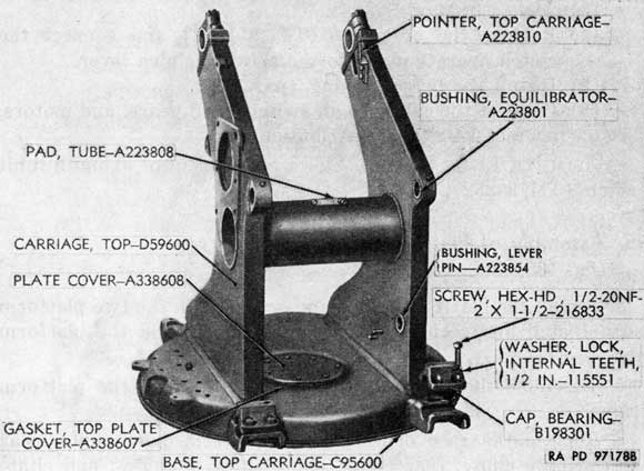
a. This section covers the top carriage assemblies of carriage M2A1 and mount M3 (fig. 145).
b. While these top carriages have structural differences, their designs are similar and many of the parts, including the trunnion parts, are identical.
c. The instructions given in this section pertain to the two top carriages, unless otherwise indicated.
97. Trouble-Shooting
a. EXCESSIVE EFFORT REQUIRED TO TRAVERSE WEAPON.
(1) Difficulty in traversing the gun may be caused by a damaged traversing ring gear or bearing assembly, lack of proper lubrication, or an incorrectly fitting dust seal on the top carriage.
210
Figure 145. Top carriage of mount M3.
(2) To correct, lubricate the ring gear. If lubricating or fitting the seal (par. 100 b) fails to correct the trouble, defective parts must be replaced. This requires disassembly of the top carriage assembly (pars. 98 and 100). Refer to chapter 6, section III for other causes of difficult traversing.
b. BINDING BETWEEN ELEVATING GEAR SECTOR AND PINION. This may be caused by faulty alinement of the gun on the top carriage. To correct, install shims under the trunnion bearings, as required (par. 100 k). Refer to chapter 6, section IV for other causes of binding in elevating mechanism.
98. Disassembly
a. If the top carriage base, ring gear, or bearing are to be replaced, or in an emergency, remove the top carriage unit with all the parts attached and place it on a platform high enough to provide working space underneath. Proceed to replace the parts as described below.
b. If the top carriage is to be removed as part of a general overhaul and rebuild procedure, it is desirable to have it removed without any other parts attached. To remove the top carriage, first remove the following:
c. In the case of the carriage M2A1, proceed as follows:
(1) Remove the four screws with lock washers from the cap on the contact ring and remove the cap and gasket.
(2) Remove the cotter pin and nut from the upper end of the contact ring plug.
(3) Working from the under side of the chassis, remove the eight retaining screws with washers from the bottom chassis plate and remove the plate.
(4) Remove the contact ring plug, carefully pulling it straight down from the receptacle. Wrap the plug in clean" cloth or paper to protect it from dirt or damage while it is removed. Do not remove the cable assembly from the plug.
(5) Remove retaining screws and washers and remove contact ring receptacle.
Note. The mount M3 has no contact ring assembly; the opening in the top carriage is covered with a gasket and plate.
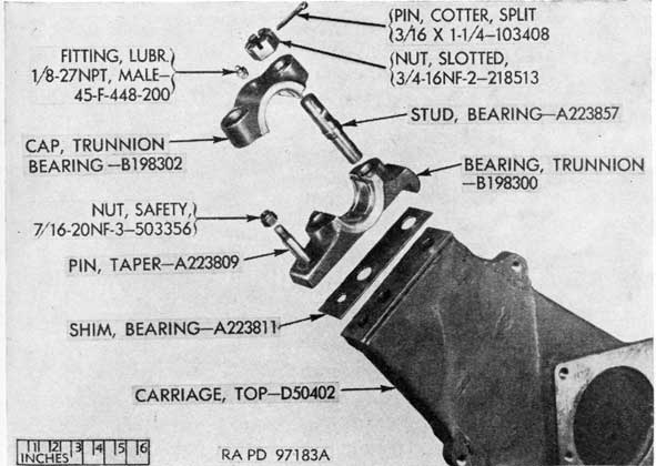
Figure 146. Trunnion bearings and related parts.
212
d. Tighten the nuts on the taper pins which position the trunnion bearings and remove the pins (fig. 146). Remove the cotter pins and nuts from the bearing studs (fig. 146). Remove the trunnion bearing caps, bearing studs, trunnion bearings, and bearing shims (fig. 146). Tag the shims.
e. Remove traversing gear inspection cover.
f. Remove level assemblies (carriage M2A1).
g. Remove top carriage pointer (fig. 145).
h. Remove equilibrator trunnion bracket bushings and the lever pin bushing (fig. 145) , if these are to be replaced. These bushings are a light press fit and can be pressed or tapped out of the top carriage body.
i. Remove tube pads (fig. 145).
j. Disassemble the elevating and traversing lock mechanisms (mount M3 only) by removing the handle, link, pins, and spring.
k. Remove the screws and nuts that secure the top carriage to the support. Secure a sling to the top carriage and by means of a hoist or crane lift the top carriage and block it securely, with the bottom up.
l. Remove the dust seal wire and remove the dust seal.
m. Remove retaining screws and remove bearing clamping ring.
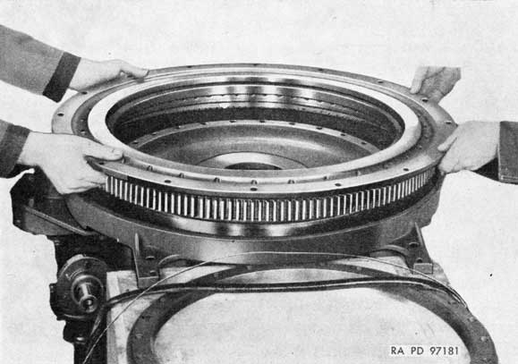
n. Remove base with attached gear and bearing from the top carriage (fig. 147).
Figure 147. Removing base with gear and bearing from top carriage.
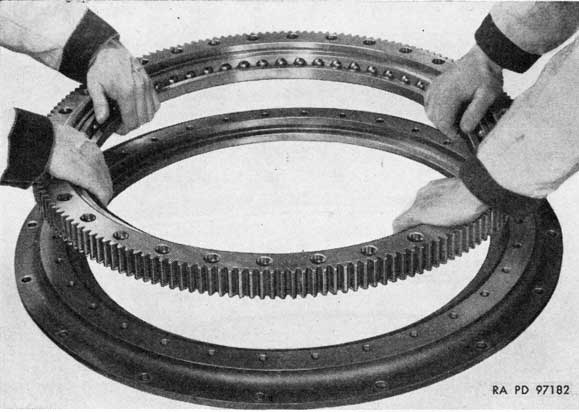
213
Figure 148. Removing gear and bearing from base.
o. Remove the screws which secure the gear to the base and remove the gear and bearing (fig. 148). Remove the bearing from the gear (fig. 149).
99. Maintenance
a. Clean all parts and inspect for wear or damage. Check parts (carriage M2A1) for surface treatment (par. 27).
b. Examine the balls or rollers for chipped or worn surfaces and see that they rotate freely. If they do not rotate freely, replace them.
c. Check the ring gear for damaged or worn teeth and breaks or cracks. If these exist, replace the gear; remove minor abrasions.
d. Lubricate the bearing assembly and wrap in clean paper if it is not to be installed immediately.
e. Check condition of equilibrator trunnion bracket bushings and lever pin bushing. If worn, distorted, or loose in top carriage body, replace the bushings.
f. Check condition of springs in elevating and traversing lock mechanisms of mount M3 (depot maintenance only). If weak or broken, replace the springs. Free height should be approximately 1 13/16 inches, solid height not more than 1 inch, and load at 1 3/8 inches, 20 pounds.
g. Remove any roughness from contacting surfaces.
214
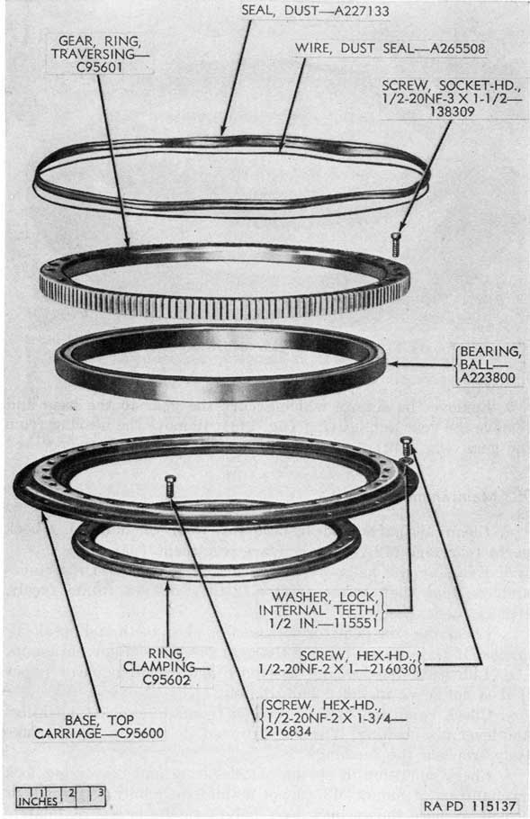
Figure 149. Parts of traversing ring gear mechanism.
215
100. Assembly
a. Install the bearing assembly in the ring gear, position gear and bearing on base, and secure ring gear to the base. Install the base with assembled parts on top carriage and install and secure clamping ring to the top carriage. Check traversing bearing race assembly for smooth operation through 360 degrees of travel, clockwise and counterclockwise.
b. Install the dust seal with dust seal wire. The dust seal supplied with carriages of early manufacture was of crescent-shape cross-section. Sometimes this seal slipped from the wire, permitting dirt to enter the top carriage. This type seal should be replaced with the newer one which has a flat surface bearing against the top carriage. Some of these seals have been found to be slightly oversize, causing difficult traversing. In such cases, grind the flat surface enough to provide a correct fit and to prevent excessive torque (par. 13 c) in traversing the gun. Install the seal with the flat side uppermost. The wire may be secured by twisting.
c. Before installing the top carriage assembly, be sure that the contacting surfaces of the top carriage and the chassis (or support) are clean and free from rust or corrosion. Apply a coating of rust-preventive compound (light) to the surfaces.
d. With a hoist and sling, raise the top carriage to position over the chassis, keeping it level. Lower the top carriage carefully, guiding it into place to avoid damaging the contact ring receptacle. Install the retaining screws with washers and safety nuts. Tighten the screws and nuts evenly, working alternately from opposite sides of the top carriage.
e. Assemble the elevating and traversing lock mechanisms (mount M3 only).
f. Install the tube pads (fig. 145).
g. Install the equilibrator trunnion bracket bushings and the lever pin bushing (fig. 145). These bushings are a light press fit and should be tapped or pressed in carefully to prevent distortion.
h. Install the top carriage pointer (fig. 145).
i. Install the traversing gear inspection cover.
j. Install the level assemblies (carriage M2A1).
k. Install the bearing shims (fig. 146). If it is necessary to reduce backlash between elevating gear sector and pinion (par. 75), install thinner shims, using shims of equal thickness for both bearings. If it is necessary to correct binding between elevating gear sector and pinion (par. 75), install thicker shims, using shims of equal thickness for both bearings. If it is necessary to correct vertical alinement of gun with respect to top carriage
216
(par. 16 c), use shims of different thicknesses for each bearing, keeping in mind that the corrections for the bearings are opposite in nature, that is, if shims are added for one bearing, shims must be subtracted for the other bearing.
l. Install the trunnion bearings in position and screw in the bearing studs (fig. 146). Install the safety nuts on the taper pins and drive the pins in place, seating them securely (fig. 146). Replace the trunnion bearing caps and secure with the nuts and cotter pins (fig. 146).
m. In the case of the carriage M2A1 proceed as follows:
(1) Install contact ring receptacle.
(2) Unwrap the contact ring plug. Be sure that it is thoroughly clean and install it in the receptacle, working it carefully into position. Avoid damaging the spring brushes in the receptacle. Install the nut and cotter pin on the upper end of the contact ring plug.
Caution: Do not screw nut down too far as it may cause the spindle to bind and shear off.
(3) Install the cap and gasket with four screws and lock washers over the end of the plug.
(4) Install the chassis bottom plate, with the notch in the bracket engaged with the lug on the contact ring plug. Install the plate retaining screws with lock washers.
Note. The mount M3 has no contact ring assembly; cover the opening in top carriage with gasket and plate (fig. 145).
a. ADJUSTMENT OF LEVEL ASSEMBLIES (CARRIAGE M2A1).
(1) Elevate gun to maximum, traverse the top carriage so that it is parallel to the longitudinal girder, then roughly center the vial bubbles by means of the leveling jacks.
(2) Accurately center the cross level vial by means of the outrigger jacks and traverse the gun 180°. Correct half the vial error by shimming the low end of the vial casing. Recheck at 180° and again correct, if necessary, using the same procedure.
(3) When vial is level at 180° intervals, traverse 90° and
217
center the level vial by means of the longitudinal girder jacks. Recheck at 180°.
(4) The carriage is now leveled so that the longitudinal vial may be adjusted to level by use of shims with the top carriage in any position. Recheck both vials at 90° intervals.
b. ADJUSTMENT OF THE TOP CARRIAGE POINTER.
(1) Check the accuracy of the top carriage pointer, using the gunner's quadrant to determine the gun elevation.
(2) If elevation readings indicated by the pointer vary from those of the quadrant, tap the pointer with a hammer to move it the necessary amount.
c. ADJUSTMENT OF TRUNNION BEARINGS.
(1) Check for backlash in elevation and also for binding (par. 12); check vertical alinement of gun with respect to top carriage (par. 16 c).
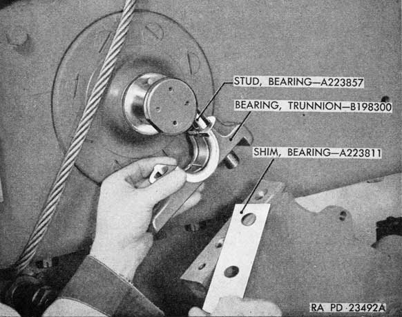
(2) If adjustment is necessary, remove trunnion bearing caps, raise gun with a sling and hoist high enough to permit removal of trunnion bearing (fig. 150) and apply the shimming corrections (par. 100 k).
(3) Repeat the above tests and make any required changes in shims to insure satisfactory operation.