40-MM Wet Mount Assemblies (Single), OD 5853, 1947 describes modifications to the Army single Bofors 40mm gun for use on submarines. The images were captured with a hand held camera and are not as good as we would like.
In this online version of the manual we have attempted to keep the flavor of the original layout while taking advantage of the Web's universal accessibility. Different browsers and fonts will cause the text to move, but the text will remain roughly where it is in the original manual. In addition to errors we have attempted to preserve from the original this text was captured by optical character recognition. This process creates errors that are compounded while encoding for the Web.
Please report any typos, or particularly annoying layout issues with the Mail Feedback Form for correction.
NAVY DEPARTMENT
BUREAU OF ORDNANCE
WASHINGTON 25, D. C.
RESTRICTED
October 1947
ORDNANCE DATA 5853
40-MM WET MOUNT ASSEMBLIES (SINGLE)
1. The purpose of these data is to provide information concerning the design, operation, and maintenance of the 40-mm Mount Mark 3 Mod 6, 40-mm Machine Gun Mechanisms Mark 5 Mods 2 and 3, and 40-mm Sight Mark 8 Mod 3.
2, These assembled units are merely modifications of service equipments to provide for more satisfactory wet use.
3, This publication, does not supersede any existing publication. This publication is intended for use with the following publications: War Department technical manuals TM 9-252 and TM 9-1252; War Department Technical Bulletin TB 9-252-9; Ordnance Pamphlet 820 (Preliminary).
4, This publication is RESTRICTED and shall be safeguarded in accordance with the security provisions of U.S. Navy Regulations, 1920, Article 76.
A. G. NOBLE
Rear Admiral, USN
Chief of Bureau of Ordnance
K. H. "Noble
Captain, USN
Acting
ii
RESTRICTED
NAVORD 5853
40-MM WET MOUNT ASSEMBLIES (SINGLE)
* * *
40-MM MOUNT MARK 3 MOD 6
40-MM MACHINE GUN MECHANISM MARK 5 MODS 2 AND 3
40-MM SIGHT MARK 6 MOD 3
* * *
DESCRIPTION, OPERATION,
AND MAINTENANCE INSTRUCTIONS
The 40-mm wet mount assemblies described in this publication consist of 40-mm Automatic Guns M1 and 40-mm Mounts M3, and associated equipment, modified by the performance of various Ordalts. Accomplishment of Ordalt 2206 increases the length of time that these equipments, which were not designed for wet use, can be kept in serviceable condition. The modifications of Ordalt 2206 consist primarily of substitutions of corrosion resistant metals for various pins, springs, bolts, and other small parts, and the addition of a number of grease fittings to provide positive lubrication of critical bearings. Most non-working surfaces are painted and numerous parts are plated with chromium or cadmium.
The two 40-mm wet mount assemblies described herein have components as follows:
Assembly Number
443
621
Mount
Mk 3 Mod 6
Mk 3 Mod 6
Consisting of Stand
Mk 3 Mod 1
Mk 3 Mod 1
Consisting of Carriage
Mk 5 Mod 5
Mk 5 Mod 5
Machine Gun Mechanism
Mk 5 Mod 2
Mk 5 Mod 3
Gun Barrel
M-1
M-1
Sight
Mk 6 Mod 3
Mk 6 Mod 3
40-mm Mount Mark 3 Mod 6
This mount is a modification of the 40-mm Gun Mount M3 which is described briefly in War Department Technical Bulletin TB 9-252-9. The gun mount M3 is basically the same as the top carriage of the 40-mm Antiaircraft Gun Carriage M2A1, the description and operation of which are covered in War Department Technical Manual TM 9-252.
The Mount Mark 3 Mod 6 differs from the gun carriage M2A1 in the following important respects:
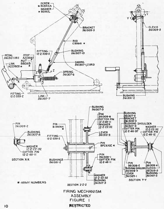
(a) No rear firing pedal is provided. Other changes to the firing mechanism were necessitated by removal of the rear pedal. The modified firing mechanism assembly is shown in Figure 1.
2
(b) The elevating gear and training gear are entirely manually operated.
(c) The direction of rotation of the training hand-wheels is reversed. Rotation of the handwheels clockwise from the right produces clockwise rotation of the carriage.
(d) Seat posts are moved outboard to place them more nearly in line with the sights.
(e) Train and elevation securing pins and train stops are provided.
(f) A deflector has been provided at the end of the case chute to deflect the empty cartridge cases downward.
(g) Handrails and ammunition racks have been added.
(h) The equilibrators have been changed to provide ready disassembly for maintenance.
(i) Changes necessary to minimize corrosion and to facilitate lubrication at critical locations have been incorporated,
(j) The training circle is doweled to the stand.
40-mm Machine Gun Mechanism Mark 5 Mods 2 and 3
These gun mechanisms are basically the same as the 40-mm Automatic Gun M1, the description and operation of which are covered in War Department Technical Manual TM 9-252. The Gun M1 for Navy use is designated 40-mm Machine Gun Mechanism Mark 5 Mod 0 and differs from the Gun M1 for Army use in that a glycerine-water mixture is used in the recoil cylinder and several additional minor changes are incorporated. The 40-mm Machine Gun Mechanism Mark 5 Mod 0, when modified in accordance with Ordalt 2206 for wet use, is designated Mark 5 Mod 2. The designation becomes Mark 5 Mod 3 when the hand operating lever is modified and the slide of mechanism Mark 5 Mod 2 has additional holes for the installation, at a later date, of the 40-mm Sight Mark 8 Mod 0.
3
The instructions for Loading, Firing, and Securing, Chapter VI of OP 820 (Prel.), must be followed for operation of the gun mechanism.
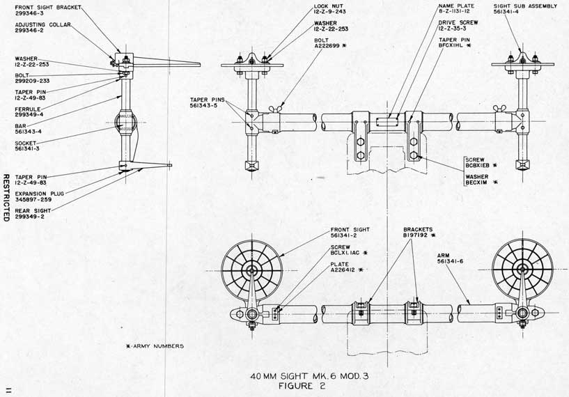
40-mm Sight Mark 8 Mod 3
This sight consists of a pair of front rings and rear sights similar to those used with 40-mm Sights Marks 3 and 4 (for twin and quad mounts), mounted on the supporting pipe structure, which in turn is mounted at the forward top surface of the slide. See Figure 2. The front rings are provided with vertical and horizontal adjustment. Both sights are mounted 27 inches from the centerline of the gun.
The following table indicates the approximate amount of lead required at ranges of 1,000 yards and 3,500 yards against targets whose speed components across the line of sight are as listed:
Sight Ring
Speed Component
1,000 Yard Range
3,500 Yard Range
1st (Inner)
75 Knots
50 Knots
2nd
150 Knots
100 Knots
3rd
300 Knots
200 Knots
4th (Outer)
450 Knots
300 Knots
For aligning the sights with the gun, a 40-mm Bore Sight Mark 2 Mod 0 and a sight testing target are required.
See OP 820 (Prel.) for information concerning the bore sight. The testing target should be made to the dimensions shown in Figure 3 and should be planed perpendicular to the bore of the gun at 50 to 150 feet from the mount. The line A-B of the target should be parallel to the plane of the roller path, a condition which exists when the line of sight moves along or parallel to line A-B as the mount is moved in train.
To check the alignment of the sights proceed as follows:
1. Open the top door of the gun mechanism, lower the breechblock, and insert the breechblock locking bolt.
2. Insert the bore sight in the breech end of the gun barrel so that the aperture of the gun muzzle is clearly visible and centered in the inclined reflecting surface of the bore sight.
4
3. Train and elevate the gun as required until the, reflected image of the point "C" of the target is centered in the aperture of the gun muzzle.
4. If the sights are properly aligned, the lines of sight will intersect the target crosses.
If the sights are not in line, make the following adjustments:
1. Loosen the two locknuts of the front sight until the sight can be moved horizontally to a position in which the line of sight intersects the vertical line of the target.
2. Tighten the nuts slightly and then turn the adjusting collar until the line of sight intersects the cross on the target.
3. Tighten the locknuts securely.
5
MAINTENANCE
The following instructions and, except as noted below, the routine maintenance instructions of Army Technical Manuals TM9-252 and TM9-1252, must be observed to obtain satisfactory operation of these assemblies in wet installations.
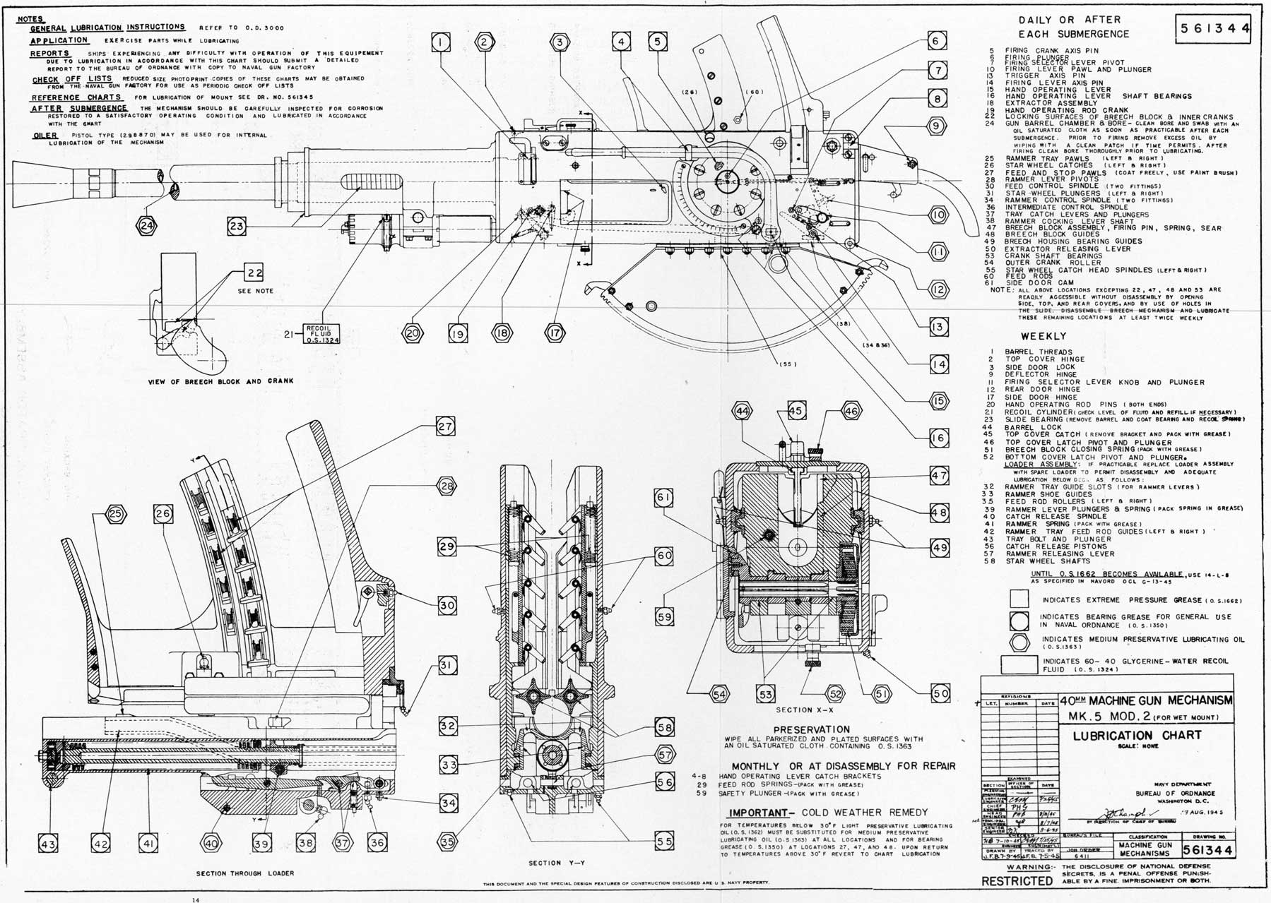
Lubrication
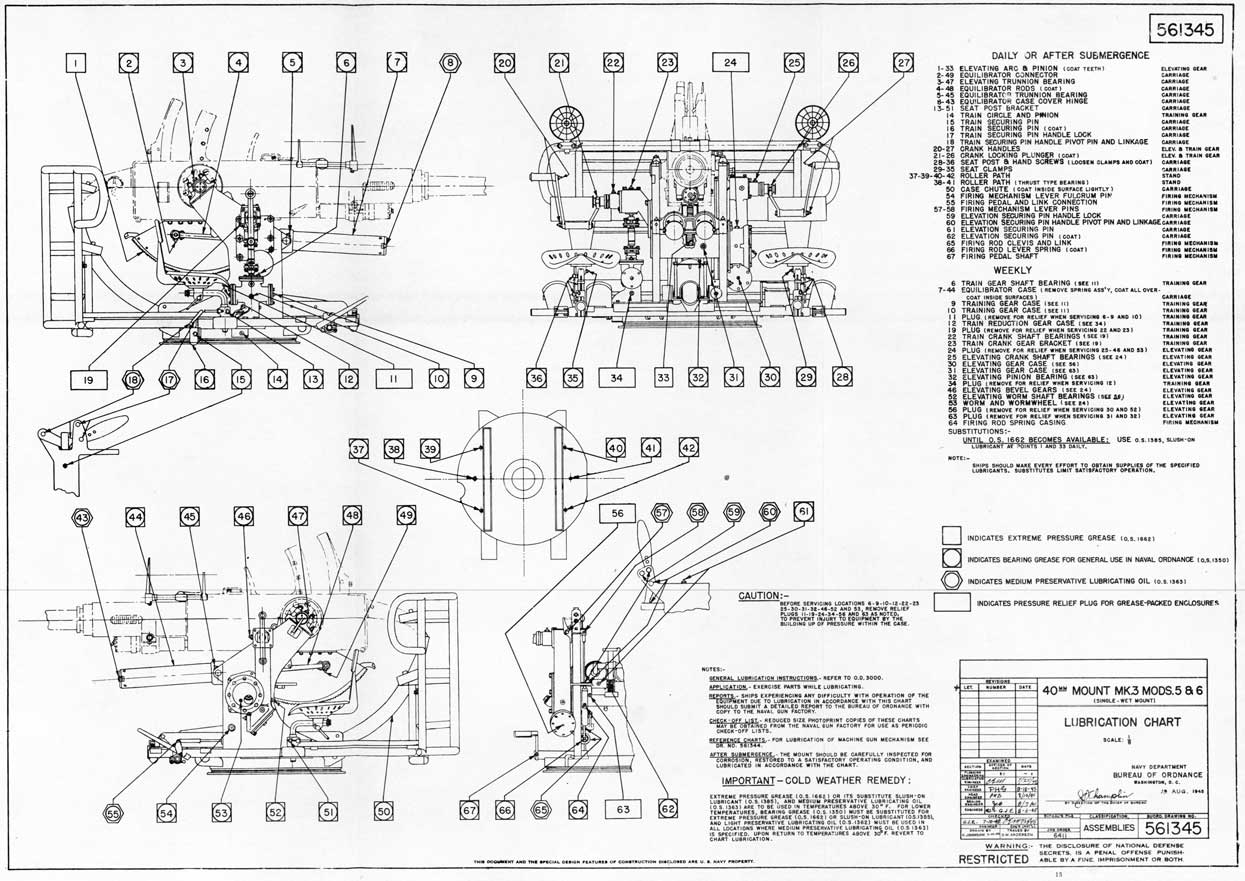
Detailed lubrication instructions are provided in the lubrication charts appended. (BuOrd Drawing 561344 and 561345).
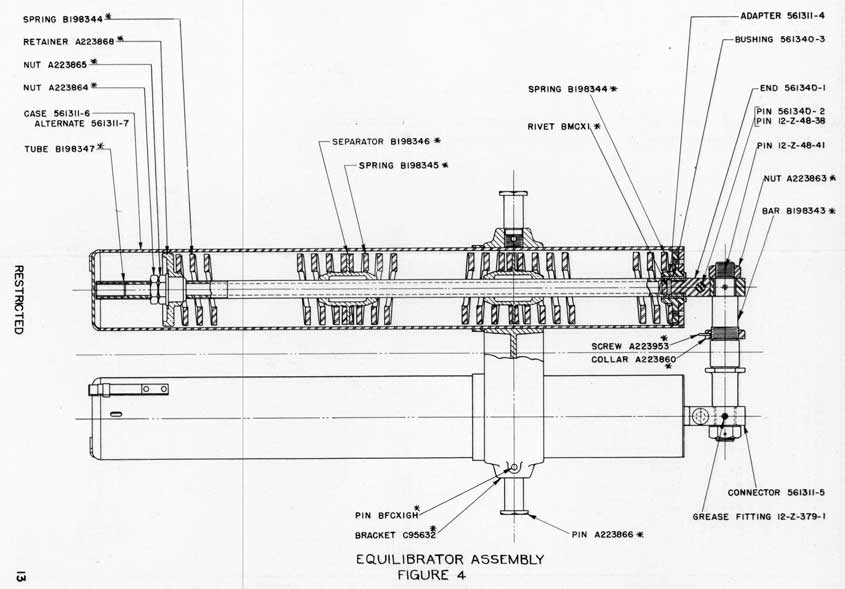
The equilibrator spring assemblies are designed for ready removal for lubrication as follows (see Figure 4):
(a) Remove the cotter pins, 12-Z-48-38, from the connector pins, 561340-2. For this purpose the gun should be depressed to a position where the cotter pins are readily accessible.
(b) Elevate the gun to maximum elevation. To prevent the gun from falling when the connector pins, 561340-2, are removed, secure the elevating hand crank against rotation by tying a rope to the crank and to a suitable point on the mount.
(c) Remove the connector pins, 561340-2.
(d) Slide the spring assemblies out the forward end of the cases, 561311-6 or 7, in the assembled condition, allowing the cases to remain in the bracket, C-95632, on the mount. CAUTION: - Do not attempt to move the guns in elevation by means of the hand crank alone while the equilibrators are disconnected, as the resulting overload on the elevating mechanism may damage the gears. If it is necessary to elevate or depress the guns while the equilibrators are disconnected, use a block and tackle to relieve the unbalanced load.
(e) The spring assemblies may be replaced by reversing the above procedure,
6
Daily Check
The routine check-off procedure described below should be followed daily to insure that all critical parts are functioning properly:
(a) Check operation of the breechblock firing mechanism by pulling the hand operating lever about 30 degrees to the rear to cock the firing pin. An audible click should be heard. Let the lever go forward to release the firing pin. This operation should produce another click.
(b) Move the firing selector lever to its various positions - stop fire, single fire, and automatic fire. This lever should operate very easily.
(c) Move the extractor release lever.
(d) Depress and release the feed and stop pawls to insure that all the feed and stop pawls and springs are in good working order.
(e) Push on the feed control lever in the feedway of the loader. This should cause the right rammer check lever to be depressed. Release the feed control lever. The right rammer check lever should rise quickly.
(f) Reach through the rear door and manually depress each of the rammer tray pawls. These pawls should rise quickly and freely upon release of pressure.
(g) Press and release the firing pedal several times. Note the position and operation of the left rammer check lever. With the firing selector lever on "single fire" the lever should be depressed once and then should release through the action of the firing lever pawl and snap back into the up position, while the firing pedal remains depressed. With the firing selector lever on "auto fire", the left rammer check lever should remain depressed while the firing pedal is depressed and should rise quickly upon release of the firing pedal.
(h) Place a dummy round in the loader. Pull the hand operating lever all the way back to cock the rammer and open the breechblock. Place the hand operating lever in the rear bracket. Use the shell pusher,
7
C95031, to push the round through the feed rollers on to the tray. Return the hand operating lever to the forward bracket. Press the feed control lever. Listen for the click that indicates release of the rammer shoe by the right rammer check lever. Depress the firing pedal and note that the dummy round catapults into the chamber and that the breechblock closes properly. Remove the dummy round from the gun.
(i) Exercise the train and elevation securing pins.
(j) Train and elevate through the entire arc of operation several times.
If the foregoing check procedure indicates sluggish or abnormally stiff operation of any parts, these parts should be disassembled and thoroughly cleaned and lubricated.
Weekly Check
It is recommended that one round be fired weekly. If firing is not practicable the procedure described below should be followed weekly:
(a) Remove the loader assembly in accordance with the lubrication chart (Dr. No. 561344).
(b) Remove the breechblock assembly and the extractors.
(c) Remove the gun barrel.
(d) Exercise the recoil cylinder by pulling or pushing the housing back and forth in the slide several times. If the piston rod is corroded, the rust should be carefully removed and the rod oiled lightly with medium preservative lubricating oil, OS 1363. (Pull housing with a rope, if necessary).
(e) Reassemble the gun mechanism.
General
All finished faying surfaces of parts that were disassembled for accomplishment of Ordalt 2206 have been coated with zinc chromate primer, Navy Spec. No. 52P18.
8
Most non-working surfaces on the carriage and all non-working, unplated surfaces on the gun mechanism have been painted with paint No. 22, Ord, Standard No. 52. These surfaces should be cleaned and recoated, as necessary, with the original type of primer and paint. Care should be exercised in the cleaning process that no old paint enters bearings or is deposited on working surfaces. Working surfaces should also be adequately protected during the painting process.
During cleaning, if any part has a spot of corrosion, the spot should be carefully removed before relubricating or repainting.
It is recognized that modification of 40-mm guns and mounts in accordance with Ordalt 2206 will not prevent corrosion of many parts, but the Ordalt was intended to improve operation and reduce maintenance to the greatest practicable extent. There are a great number of parts on which slight corrosion will not seriously affect the operation of the gun or mount. If these parts were plated or manufactured from corrosion resistant materials, the procedure would increase the cost and amount of work for the performance of the Ordalt without affording a commensurate gain in service performance or ease of maintenance.
9
APPENDIX
Installation Data
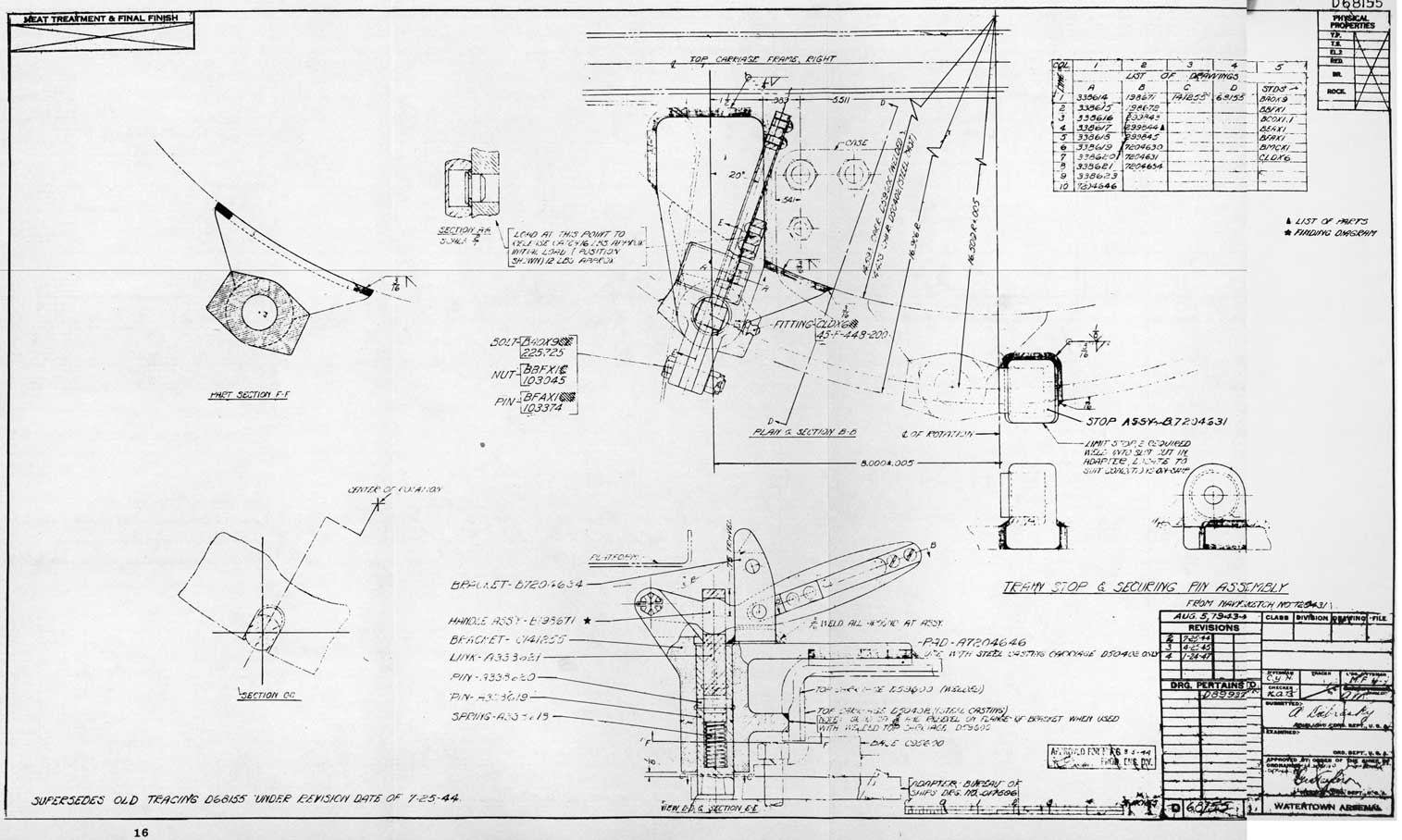
General installation data will be found on BuOrd Sketch No, 119793, 40-mm Single Mount, Working Circle, At installation of the mount, the adaptor plate to which the mount is bolted should be slotted for the train securing pin as shown on Army Drawing D68155, page 16. The location of the slot should be determined to provide the desired securing position. The adaptor plate should be modified locally at the securing pin to provide full bearing width for the pin, if necessary. Train stops should be welded to the adaptor plate as shown on Army Drawing D68155 to limit the train angle as desired. The adaptor plate should be built out locally if necessary to provide adequate support for the stops.
Ordering of Parts
Parts should be ordered from the following lists of drawings:
Sk. 107714 - Army 40-mm Gun Barrel M1
Sk. 108054 - 40-mm Stand for Carriage M3 (40-mm Stand Mark 3 Mod 1)
Sk. 139700 - 40-mm Carriage Mark 5 Mod 5
Sk. 139703 - 40-mm Sight Mark 6 Mod 3
Sk. 165205 - 40-mm Machine Gun Mechanism Mark 5 Mod 2
Sk. 165436 - 40-mm Machine Gun Mechanism Mark 5 Mod 3
Sketch Lists 165205 And 139700 indicate certain pieces for which new numbers were assigned to identify a new part, but no drawing was prepared. Reference is made in each case to another drawing for dimensional information, New parts should be ordered by the number indicated in column 1 of the sketch lists.
A complete set of drawings for these assemblies should consist of all the drawings listed in both columns 1 and 2 of the above sketch lists excepting those drawings indicated by a small circle to show that no drawing has been prepared.
10
11
12
13
14
15
16
17
SAFETY PRECAUTIONS
1. A 40-mm gun must be considered a "loaded gun", whenever there is a live round in the gun barrel, on the rammer tray, or in the loader, and under these conditions safety precautions applicable to "loaded guns" must be observed.
2. Attention is particularly directed to the fact that depression of the gun below the horizontal may result in accidental discharge, when there is a loose round on the rammer tray free of the rammer levers. This condition will not occur in normal operation.
3. See that the breechblock locking bolt is inserted FULLY before loading, unloading, or investigating a stoppage. (If the breechblock is closed after a stoppage, the locking bolt cannot be inserted fully. Keep the gun pointed in a safe direction without the locking bolt inserted, until danger of cook-off has subsided. See Ordnance Pamphlet 1591. Do not investigate the stoppage until the breechblock has been opened and the locking bolt inserted.)
4. When resuming fire after a gun stoppage, never push a new round down onto the rammer tray until it has been definitely determined that the barrel, breech, and rammer tray are clear.