Figure 28
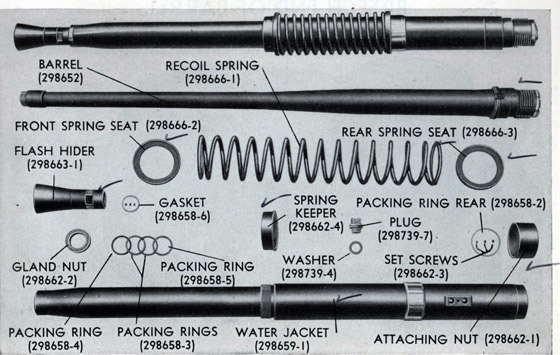
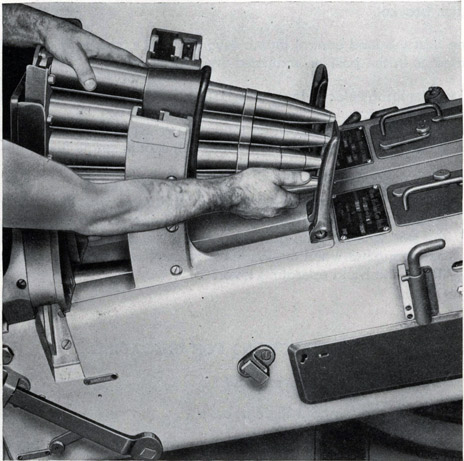
A complete barrel assembly is shown at the top of the illustration; below the assembly are shown its individual parts.
The Barrel Assembly, Figure 28, includes a 40MM Barrel, Mark 1, its water jacket, a flash hider, and a recoil spring. The barrel assembly is inserted in the cylindrical fore part of the slide and engaged, by a half turn to the right, with mating interrupted threads in the housing. This half turn brings uppermost the barrel interlock slot in the breech end of the barrel, where it receives the barrel lock upon closure of the top door.
1. 40MM Gun Barrel, Mark 1
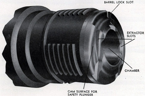
The breech face of the barrel, Figure 29, is also provided with vertical slots to accommodate the extractors, and a cam surface to actuate the breech block safety plunger which is assembled in the housing. The bore is rifled with sixteen grooves having a right hand twist. The rifling is of increasing twist-one turn in 45 calibers at the origin to one turn in 30 calibers at the muzzle.
52
BREECH END OF BARREL
Figure 29
2. Water Jacket
The water jacket covers the barrel; it is installed over the muzzle end and is retained in place by an attaching nut at the rear end of the barrel. A cooling liquid is circulated through the jacket by a motor driven pump located on the mount.
3. Flash Hider
The flash hider is screwed on the end of the barrel, and is held in place by three set screws. Hexagonal surfaces provide a place for application of the two handled wrench used in installing and removing the barrel.
4. Recoil Spring
The recoil spring is assembled over the fore end of the water jacket. The rear spring seat abuts against a sleeve welded to the outside surface of the water jacket. The recoil spring is retained at its forward end by a spring keeper threaded onto the water jacket. The sleeve on the water jacket provides a bearing surface for the assembly within the cylindrical fore part of the slide.
53
Chapter IV
SIGHTS
A. DESCRIPTION OF SIGHTS
The sights provide a simple means of giving the necessary lead to allow for target motion during the time of flight of the projectile, and also provide for quick changing of the lead, as the position of the target changes. When the gun is controlled by means of the director, these sights are not used.
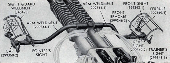
Figure 30
Mark 3 sight shown in position on the gun mechanisms of a twin mount.
1. 40MM Sight, Mark 3
The 40MM Sight, Mark 3, Figure 30, is used with a pair of 40MM Machine Gun Mechanisms installed in a 40MM Mount, Mark 1 (Twin). The sight arm weldment is bolted to pads on the front end of each of the slides.
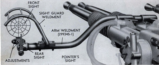
2. 40MM Sight, Mark 4
The 40MM Sight, Mark 4, Figure 31, is used with two pairs of 40MM Machine Gun Mechanisms installed in a 40MM Mount, Mark 2 (Quad). It differs from the Mark 3 Sight by having two sight arm weldments, each of which is bolted to pads on the front end of the slides on a pair of mechanisms.
3. Pointer's and Trainer's Sights
Each 40MM Sight, Mark 3 or Mark 4, includes a pointer's sight on the left end and a trainer's sight on the right end of the sight arm weldment. The
54
rear sight of each consists of a vertical post with a peep sight at its upper end. The front sight is a ring type sight consisting of four concentric rings provided with radial strips. Provision is made for vertical and horizontal adjustment of the front sight.
Figure 31
The Mark 4 sight has two separate arm weldments. The pointer's sight of the Mark 4 sight is shown in position on the gun mechanisms of a quad mount.
B. USE OF SIGHTS
The following tables indicate the approximate amounts of lead required at ranges of 1,000 yards and 3,500 yards against targets whose speed components across the line of sight are as listed in the tables.
1,000 Yard Range
3,500 Yard Range
Sight Ring
Speed Component
Sight Ring
Speed Component
1st (Inner)
75 knots
1st (Inner)
50 knots
2nd
150 knots
2nd
100 knots
3rd
300 knots
3rd
200 knots
4th (Outer)
450 knots
4th (Outer)
300 knots
55
C. ALIGNMENT OF SIGHTS
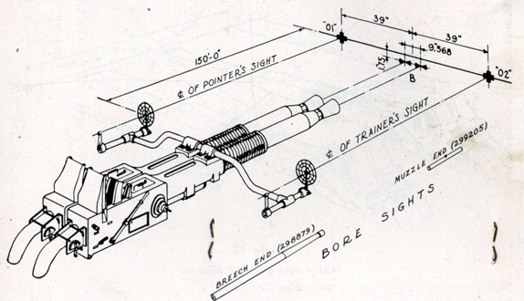
For aligning the sights with the gun, a bore sight and a sight testing
target are required. The bore sight consists of two parts, a breech end (298879) and a muzzle end (299205). The 40-mm Boresight Mk 2 Mod 0 consists of one part, the forward end of which is plug-shaped and fits into the breech end of the barrel. It is provided with
at the center anti a mirror at the after end for deflecting the line of sight 90°. A sight testing target, Figure 32 for the Mark 3 Sight and Figure 33 for the Mark 4 Sight, may be constructed and used after the gun has been placed in service. The target is made to the
Figure 32
Mark 3 sight alignment diagram.
dimensions shown in the diagram, and placed approximately one hundred fifty feet in front of the gun, at right angles to the gun bore, and with line "01-02" " of the target parallel to the center line of the trunnions.
1. Checking the Alignment
To check the alignment of the sights, proceed as follows:
a. Lower the breech block.
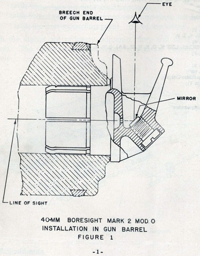
b. Insert the boresight in the breech end of the gun muzzle is clearly visible and centered in the inclined reflecting surface of the boresight (See Fig. 1 of Change 3).
56
c. Train and elevate the gun as required until the reflected image of the corresponding point "B" of the target is centered in the aperture of the gun muzzle.
40-MM BORESIGHT MARK 2 MOD 0
INSTALLATION IN GUN BARREL
FIGURE 1, CHANGE 3
a. Loosen the two lock nuts of the front sight until it can be moved horizontally to a point at which the vertical center line of the sight is in line with the rear sight and the black cross on the target.
b. Tighten the nuts slightly and then turn the adjusting collar until the horizontal center line of the front sight is in line with the rear sight and the black cross on the target.
c. Tighten the lock nuts securely.
Upon completion of the sight check and adjustment, remove the boresight. The mirror of the boresight should be cleaned, if necessary by dusting with a camels hair brush and rubbing lightly with a soft, clean cloth.
The 40-mm Boresight Mk 1 may be available on larger ships and stations. If available, it may be used in place of the 40-mm Boresight Mk 2 Mod 0.
57
Chapter IV
CYCLIC OPERATION
Cyclic Operation of The Gun Mechanism
In automatic fire, one complete cycle of operation occurs approximately every half second. In each cycle the following basic functions are performed:
A live round is fed onto the tray.
The rammer is cocked.
The round is rammed into the barrel chamber. The breech is closed.
The round is fired.
The empty case is ejected.
These basic functions are shown step by step in the following diagrams, following a round through the complete cycle from feeding to ejection. In these diagrams, the cool colors (green and blue) are used to indicate the parts of the gun mechanism that move in recoil, while the warm colors (red, orange, and yellow) are used to indicate other moving parts.
58
A. FEEDING THE ROUND Figure 34
The barrel assembly, breech mechanism, and tray are moving forward in counterrecoil. The breech block is held down by the extractors, and the rammer shoe is held back by the tray catch lever. The star wheels are released, the catch heads of the catch mechanisms having been tripped by the rammer tray pawls. The feed pawls, due to the action of the tray guides, are pressing the rounds down. This forces the bottom round between the star wheels and onto the tray.
B. COCKING THE RAMMER Figure 35
The barrel assembly, breech mechanism, and tray are still moving forward in counterrecoil and have almost reached battery position. The live round is now on the tray with its base in the slots of the rammer levers. The rammer shoe is being held back by the tray catch lever, and as the tray moves forward, the rammer spring is compressed, cocking the rammer. The trigger catch lever is held down by the trigger mechanism, and the loader catch lever is held down by the rounds in the loader. This leaves only the tray catch lever holding the rammer shoe.
The parts that were moving forward in counterrecoil have now reached battery position. The beveled cam on the under side of the tray has ridden over the forward end of the rocker arm, tripping the tray catch lever, thus allowing the rammer shoe and levers to be thrown forward by the action of the rammer spring. As the rammer levers neared the forward limit of their travel, they were spread apart by the cam slots of the tray through which they extend. This allows the round to continue its travel and be thrown into the barrel chamber.
D. CLOSING THE BREECH Figure 37
The round is completely in the chamber and the closing spring is raising the breech block to the closed position. The breech block is free to rise, because the extractors were unhooked from the block by the base of the round as it was thrown into the chamber. As the block rises, pressure of the cam on the left inner crank is removed from the outer cocking lever. The firing pin is being held back only by the inner cocking lever which is prevented from moving by the sear.
62
E. FIRING THE ROUND Figure 38
The breech is completely closed and the round is fired. Firing occurs after the breech is closed, by the action of the cam of the right inner crank upon the sear. The cam forces the sear inward, releasing the inner cocking lever and the firing pin. The firing pin strikes the primer, which explodes the propellant charge of the round.
F. EJECTING THE CASE Figure 39
The barrel assembly, breech mechanism, and tray are moving rearward as a result of the momentum imparted by the powder pressure at the beginning of recoil. The breech block is in the open position, the outer and inner cranks having been rotated by action of the roller, riding against the cam surface of the side door. The firing pin is cocked by action of the cam of the left inner crank depressing the outer cocking lever. As the breech block descended, it struck the toes of the extractors, ejecting the empty case. The feed pawls, due to the action of the tray guides, are rising in order to feed the next round onto the tray.
A complete cycle has now taken place, and the action repeats itself in automatic fire as long as the loader is supplied with ammunition and the trigger mechanism is held in the firing position.
2. Move the hand operating lever all the way to the rear, then latch it in the rear catch bracket.
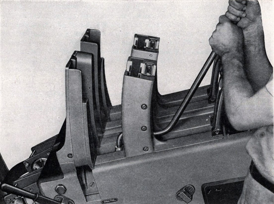
3. Push a full clip into the loader, so that one round drops onto the rammer tray. When the clip is pushed in far enough to accomplish this, the empty clip will be ejected through the clip chute. Place another full clip in the loader.
4. Move the hand operating lever forward and latch it in the forward catch bracket.
5. See that the feed control thumb lever on the loader rear guide, if provided, is in the position indicated by the red arrow.
6. Place the firing selector lever on AUTO FIRE or SINGLE FIRE as desired.
7.
a. Hold the firing pedal of the mount down for automatic fire. b. Press the firing pedal smartly for each shot in single fire.
8. Keep the loader filled.
The loader catch lever will stop operation, with the rammer shoe cocked, when only two rounds remain, one on the tray and one on the star wheels. The gun mechanism is then in condition to resume automatic fire when the loader is refilled, without further manipulation of the hand operating lever.
B. INSTRUCTIONS FOR UNLOADING
1. Place the firing selector lever on SAFE.
2. Elevate the gun to about 30 degrees.
3. Move the hand operating lever all the way to the rear, making sure an assistant catches the live round thus released from the rammer levers, as the round slides through the opening in the rear door.
4. Place the hand operating lever in the rear catch bracket.
66
5. Install the round releasing tool (298899) in the side frames, Figure 40, compressing the feed and stop pawls.
6. Lift out the rounds which have been released. Remove the round releasing tool.
7. Using the pusher tool (298876), Figure 41, force the round on the star wheels down on to the rammer tray. Remove the round.
8. Move the hand operating lever fully forward to release the star wheel catch mechanisms, and then latch it in the rear catch bracket.
Figure 40
Using the round releasing tool.
67
9. Use the pusher tool to force the last round through the star wheels on to the tray. Remove the round as before.
10. When the loader is empty, secure the hand operating lever in the forward catch bracket. Trip the extractors with the extractor release lever to close the breech block.
11. Depress the feed control lever in the rear guide and then release it. This operation will release the rammer shoe from the loader catch lever. Place the firing selector lever at either firing position. Press the firing pedal of the mount smartly to release the rammer shoe from the trigger catch lever.
12. Place the firing selector lever on SAFE.
Figure 41
Using the pusher tool.
68
This ship is blank.
69
Chapter VII
CASUALTIES
In the event of a casualty, the greatest care should be exercised to insure that no actions are taken which can result in injury to personnel or material. It is important to understand that a round in the chamber can be fired unexpectedly even with the firing selector lever on SAFE, if for any reason the breech block has failed to close.
A. CASUALTIES WHICH CAN BE CORRECTED QUICKLY AND EASILY
1. Clip Placed in Loader Improperly
The most common loader failure is caused by jammed rounds, resulting from a clip not being passed into the loader properly. To free the rounds thus jammed, insert the round releasing tool (298899) in the loader to hold back the feed and stop pawls. Rounds in the upper part of the loader can then be cleared by hand. Either end of the pusher tool (298876) may be carefully used to pry the jammed rounds loose. Properly loaded rounds should be free enough to be removed by hand. Firing will continue when a new clip is placed in the loader.
2. Firing Pedal Not Fully Depressed
Depress the firing pedal fully. If the gun fires, no further examination is required.
B. OTHER CASUALTIES
1. Live Round Drops Out Into Case Chute
Open the top door.
a. If the breech block is latched down by the extractors and the empty case has been ejected, trip the extractor release lever. Closing of the breech block indicates that the breech block closing spring is not broken. Follow the normal loading procedure and continue firing. Casualties of this nature have occurred with no parts damaged and through no fault of the operator.
70
b. If the breech block is in the closed position, and a round is in the chamber, it is likely that it has failed to extract, but that recoil and counterrecoil were completed, and the ejected live round was rammed against the rear face of the closed breech block. Examination of the mechanism will probably show that the crankshaft in the housing is twisted or that the extractors are broken.
2. Live Round In the Gun or On the Rammer Tray
Place the firing selector lever at SAFE. Remove the bottom cover of the slide.
a. If the breech block is down, insert the breech block locking bolt, and then open the top door. Never open the top door when it is possible for the gun to fire. Remove the round through the rear door, and examine the mechanism for damaged parts, such as, broken extractors, twisted crankshaft, broken breech block closing spring, broken rammer rod or spring. Examine the round to determine, if possible, the cause of the trouble. If the gun was at a low angle of elevation when this stoppage occurred, it may have been the same type of casualty as the one described in 1. a. above, when a live round dropped out into the case chute.
b. If the breech block is closed, and if examination of the tray through the opening in the rear door,-without removing the case deflector,-discloses a live round on the tray, the case in the chamber is presumably empty, and the casualty should be treated as in paragraph 1. b. above, after removal of the live round.
c. If the breech block is closed and a live round is not on the tray or in the case chute, and examination through the bottom opening in the slide shows the base of a case in the gun, a misfire has occurred and the procedure will be governed by the applicable Naval Regulations. If the breech block is not fully closed for any reason, the firing pin will not be released at all. In such cases, the breech block may slowly close itself and fire the gun after an apparent misfire, by wedging action of the breech block finally seating a round in a dirty chamber, by slow action of a gummy breech block, etc. A situation of this kind can usually be determined by examination of the sear in the bottom of the breech block.
(1) If the sear is to the left, that is, the head of the sear is fully in the mating slot, the firing pin has been released and the casualty is probably a misfire.
71
(2) If the sear is to the right, that is, the head of the sear is not fully in the mating slot and is adjacent to the right inner crank, the firing pin probably has not been released but the casualty should be treated as a misfire until definite knowledge to the contrary has been determined. After removal of the round in accordance with Naval Regulations, the mechanism should be examined and tested for free operation of all parts.
3. Live Round Still Above Star Wheels
a. If a round is not on the rammer tray, in the chamber or has not dropped out into the case chute, feeding through the star wheels may have been prevented by a jammed round in the loader. In such case the feed pawl safety mechanism has operated. Remove the jammed and other rounds, force or hammer the feed pawls down into their normal positions, and follow the normal loading procedure. Failure to feed may also result from short recoil or a twisted crankshaft in the housing. Either condition may cause slow ejection of the empty case, which will not clear the star wheels in time to permit feeding of the next round.
b. If recoil is too short-less than about seven inches-feeding will be definitely prevented because the catches will not be released. If short recoil is the result of low temperature operation, firing of several rounds may warm the fluid in the recoil cylinder sufficiently to permit automatic operation. Certain of the mechanisms have throttling rods which may prevent sufficient recoil to allow reliable cold weather automatic operation. With such throttling rods, one or two ounces of the fluid in the recoil cylinder should be removed, such that recoil with service charge at approximately zero degrees elevation produces a length of recoil between 7.4 and 7.5 inches. This fluid should be replaced when warmer temperatures are encountered.
C. STAR WHEELS LOCKED
If it is not possible to push a round through the star wheels during the normal loading routine, the star wheels are probably locked by the catch mechanisms. Such a condition will result from a sheared taper pin in the bottom of the loader, in which case motion of the hand operating lever will not release the catch mechanisms. The remedy is to replace the taper pin. However, the gun may be fired normally and safely, before the taper pin is replaced, by loading the first round as follows:
72
With the hand operating lever all the way to the rear so that the rammer levers are moved to the rear and spread, carefully place a live round on the tray through the rear door opening. Move the hand operating lever slowly forward, at the same time maintaining the round in such a position that the base of the case will be caught in the slots in the rammer levers. The mechanism may then be operated normally.
D. LONG RECOIL
Long recoil will not cause stoppage but may cause excessive stresses in the mechanism. Tests indicate that with the present design of throttling rod and bushing a length of recoil in excess of about 8.3 inches is not practically attainable. However, if this maximum length of recoil is obtained, it is probable that excessive pressures are being developed in the recoil cylinder, and therefore, excessive stresses are being developed elsewhere in the mechanism. The recoil cylinder should be examined to determine if it has sufficient fluid
E. TWISTED CRANKSHAFT
An angular displacement of the housing outer crank of about five degrees, an amount readily detected, from the normal position when the breech block is closed is sufficient to make satisfactory operation doubtful. A twist of approximately eleven degrees will result in no motion of the extractors when the breech block is pulled down. In such case the crankshaft should be replaced. If the extractors are broken, they should be replaced. Even if only one extractor is broken, both should be replaced.
Twisting of the shaft may have developed gradually or may have occurred suddenly during the firing of the last round. If the casualty resulted from a single tight case, it could not have been foreseen. As a precautionary measure, the crankshaft should be examined periodically for this twisted condition. A slow speed of extraction of the empty cartridge case, resulting in a jam on the tray between the ejected case and the next round, is a danger signal that a twisted shaft may be developing. Recoil of less than about 7.2 inches may give the same result.
73
Figure 42, Page 73.
Longitudinal Section of Gun
For lateral sections indicated on this drawing, see Figures 43, 44, 45.
(Large image on a separate page.)
74
Figure 43, Page 74.
Lateral Sections Through Loader-I
Sections M-M, N-N, O-O, P-P
(Large image on a separate page.)
75
Figure 44, Page 75.
Lateral Sections Through Loader-II
Sections R-R, S-S, U-U
(Large image on a separate page.)
76
Figure 45, Page 76.
Lateral Sections Through Housing
Sections A-A, B-B, C-C, D-D, E-E, F-F, G-G, H-H, L-L
(Large image on a separate page.)
77
Chapter VIII
FUNCTIONAL CHECK-OFF LIST
A. DAILY CHECK
Breech Mechanism
1. Check operation of the breech block firing mechanism by pulling the hand operating lever about 30 degrees to the rear to cock the firing pin. An audible click should be heard. Let the lever go forward to release the firing pin. This operation should produce another click.
2. Pull the hand operating lever all the way back, then return it to the front catch bracket. Open the top door and inspect the extractors.
3. Trip the extractors with the extractor release lever. The breech block closing spring should cause the breech block to slam up.
4. With the breech block in the closed position, see that the outer crank is not displaced more than five degrees from the normal position. The toe of the crank should normally be parallel to the lower edge of the side door.
Loader
5. Pull the hand operating lever all the way back, then return it to the front catch bracket. See that the rammer shoe is held by the loader catch lever.
6. Place the hand operating lever in the rear catch bracket. Force a round through the star wheels onto the tray. Remove the round.
7. Press the feed control lever. Listen for the click that indicates release of the rammer shoe by the loader catch lever.
8. Put the firing selector lever on AUTO FIRE or SINGLE FIRE. Press the firing pedal to check operation of the rammer.