|
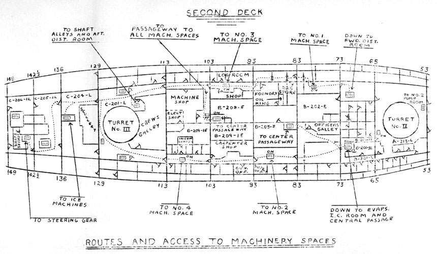
Each man should take this guide and visit each room, going over
the various possible routes many times, until he knows exactly
how to get about the ship below decks. One must realize that
many of the hatches shown will be closed during wartime cruising,
therefore alternate routes must be known.
DESCRIPTION MAIN PROPULSION INSTALLATION
The main power plant of the ship consists of four separate
engine units, each developing 32,500 horsepower and each connected
to its own propeller shaft. There are therefore four propellers.
The propeller shafts are numbered from starboard to port, numbers
one, two, three, and four respectively. Number one engine unit
in #1 machinery space drives number one shaft. But in #2 machinery
space, number four engine unit drives number four shaft. Likewise,
in #3 machinery space, number two engine unit drives number two
shaft, and in #3 machinery space, number three engine unit drives
number three shaft, This may be confusing at first, but
remember that the first two machinery units drive the outboard
shafts, while the after machinery units drive the inboard shafts.
As each of the four engine units are similar, only one need
be described. If you understand the plant in one machinery space,
you'll be familiar with the other three as all four are identical.
First we'll start with the BOILERS. There are two in each
machinery space. Each one can change 16,500 gallons of water an
hour into steam at 600 lbs. per sq. in. pressure and 850 degrees
F. Temperature. In order to do this it burns about 1400 gallons
of fuel oil per hour.
-4-
Hundreds of thousands of gallons of fuel oil are carried in
tanks spread the length of the ship along the sides and in the
bottom. Those adjacent to the machinery spaces on the side of
the ship are called service tanks; the others are called storage
tanks. Oil is pumped aboard ship through deck fittings and is
distributed to all or any desired tanks through transfer piping
by use of TRANSFER and BOOSTER PUMPS. One of these latter pumps
is located in each machinery space, and one is in a pump room
located in the HOLD between frames 46 ½ and 55. Important fuel oil
manifolds are in the forward pump room between frames 28 & 31, in
the C&R pump room between francs 46 ½ & 54, in the evaporator room,
in each machinery space, and in the outer shaft alleys. The
OIL KING is a petty officer who insures that the fuel oil is
distributed properly and is available for the boilers.
For use in the boilers, fuel oil is drawn from one of the nearby
SERVICE tanks by a FUEL OIL SERVICE PUMP. This pump discharges
through STRAINERS, FUEL OIL HEATERS, OIL LETERS, and ATOMIZERS
into the furnaces. In order to burn properly, the oil must be
at the right PRESSURE and TEMPTERATURE. It must also have the
right amount of AIR. Turbine-driven BLOWERS are therefore provided
which force air into the furnaces under great pressure. The blowers are so regulated that just the right amount of air is sent into
the furnace to burn completely all the oil sprayed by the atomizers.
Water, which the boiler turns into steam, comes from the MAIN FEED .
PUMP, through the ECONOMIZER located in the boiler uptake and then
discharges through CHECK VALVES to the steam drum. Once inside
the steam drum, the water flows down tubes in the "saturated"
side of the boiler where it is changed into steam.
-5-
This steam is known as "saturated" steam because its temperature at
600 lbs. pressure is about 489 degrees temperature. If, at that
pressure, it became cooler, it would begin to turn to water. This
saturated steam is collected by a pipe in the top of the steam drum
and sent through tubes in the "superheated" side of the boiler.
Here the steam is heated to 850 ° and is now called superheated steam,
because, at this pressure of 600 lbs, it has to cool to 489 degrees
before it begins to change to water. In other words, it is "superheated" far above the saturation point or the temperature at which
it begins to condense. The reason why steam is heated to that
temperature is that a great amount of energy is added to it which is
used to drive the engines; it would be heated to higher temperatures
if the metal of the pipes could stand up, but, at present, the steel
will soften and "creep".
At high power, over ninety per cent of the steam made in the
boiler goes out as superheated steam to drive the main engines and
the electric generators. It leaves through STOP VALVES and enters
the MAIN STEAM PIPE. The remaining ten per cent or loss of the
steam made leaves the boiler as saturated steam through STOP
VALVES and enters the AUXILLIARY STEAM LINE.
In each machinery space, some distance away from the boiler
stop valve, there is a connection to the 600 lb. auxiliary steam
line to a REDUCIG VALVE. This valve reduces the pressure from
600 lbs. to 150 lbs. and connects with a steam line known as the
150 lb. STEAM LINE. There are, then, three high pressure steam
lines: the MAIN STEAM LINE, the AUXILLIARY STEAM LINE, and the
150 lb. STEAM LINE.
-6-
The main steam line goes directly to the MAIN TURBINES, passing through the THROTTLE TRIP VALVE, the STEAM STRAINER, to the
TURBINE CONTROL THROTTLES. Ahead of the throttle trip valve is
a connection for superheated steam to the MAIN GENERATORS.
The MAIN TURBINES are the main engines of the ship. By
opening the-ahead or astern throttles, the ship is made to go ahead
or astern. When a throttle valve is opened, steam is admitted
to nozzles through which the steam blows at high velocity and strikes
blades attached to wheels on the rotor. This action causes the
rotor to turn. In the HIGH PRESSURE TURBINE, there are twelve
sets of fixed nozzles blowing steam against twelve rotating wheels
attached to the rotating shaft. These combinations of nozzles
and wheels are known as stages. At high power, when steam leaves
the last stage of the high pressure turbine, it has about 60 lbs.
pressure remaining. This can still be used to drive the ship;
so is piped over to the LOW PRESSURE TURBINE where it again
expands through nozzles against blades on the rotor as in the high
pressure turbine. When it leaves the last wheel of the low
pressure turbine, the steam has about 1 lb. absolute pressure or
about 14 lbs. less pressure then the air about us. It has also
cooled by expansion to about 100 degrees F. temperature, and it is
because of this low pressure and temperature that it is of no further
use to us for producing power. In the low pressure turbine casing
is installed the ASTERN TURBINE consisting of one pressure stage at
each end of the low pressure rotor so arranged that steam will strike
the blades and turn the rotor in the reverse direction.
-7-
But in order that the turbine can function at all, there are several
features about its construction which must be understood. Each
man must therefore investigate these features which follow, thoroughly,
The turbines are supported by BEARINGS in which the shafts or
journals as they are called rotate at high speed. Hence lubricating
oil must be supplied under pressure to these bearings to keep then
cool. Also the rotors must not move fore or aft so that the moving
wheels hit the nozzles. TURBINE THRUST BEARIGS are provided for this
purpose. In order to know whether the BEARINGS or THRUSTS are wearing, MICROMETER GAGES are installed. As steam under high pressure is
in one end of the turbine while at the other end it may be less than
that of the outside air, it is necessary to have some way of providing steam from escaping along the shaft where, it comes through the
casing, or of preventing the air from getting into the turbine. This
is done by means of GLANDS which are sealed by the GLAND SEALING SYSTEM.
This system operates automatically but its workings should
be understood by engineers. The ahead throttle reach rod connects
to a number of valves on the top of the high pressure turbine casing.
Those valves control a number of nozzles. By opening them in turn
more steam is gradually cut into the engine with the result that
the speed of the ship increases. It will also be noted that there
are valves installed at, various stages known as EXTRACTION VALVES.
These exist for the purpose of taking steam out of the turbine
to boost the pressure in the EXHAUST STEAM line which will be
discussed later. There are other connections installed for DRAINAGE
purposes.
-8-
Turbines must operate at very high speeds to work efficiently while
propellers must turn relatively slowly. The rotors of the high
pressure and low pressure turbines therefore are connected to the
pinions (high speed gears) of the DOUBLE REDUCTION GEARS, where the
high speeds of the turbine rotors are reduced so that the propeller
turns at efficient speed. The reduction gears at full power reduce
the speeds of the turbines from 6000 rpm. for the high pressure
rotor and 4000 rpm. for the low pressure rotor to 185 rpm. for the
propeller shaft. There are also a large number of bearings in the
reduction gear which require lubrication while the gears themselves
need plenty of oil. It is therefore of great importance that plenty
of cool, clean oil be delivered to the gears, and that the thermometers on the bearings be watched carefully for a rise in temperature
which indicates trouble.
On the reduction gears is a JACKING GEAR for turning the turbines and gears without the use of steam.
When the propeller turns over, the shaft moves forward, pushing
the ship. This thrust is absorbed by the THRUST BEARINGS located
forward of the gears, and it is here that the ship is actually
pushed through the water. Many thousands of pounds of pressure
as applied to this thrust at high speeds; so how it is withstood
by this device should be studied.
The SHAFTS extend from the bull gear flange to the propellers
in sections known as line shafting, stern tube shafting, and propeller
shafting. SPRING BEARINGS support the weight of the shaft and
require good lubrication.
-9-
Where the stern tube goes through the side of the ship is a STERN
TUBE bearing. Water is prevented from entering the ship by a STERN
TUBE GLAND. How to keep these spring and stern tube bearings cool
should be investigated.
The THROTTLEMAN by means of his GAGE BOARD controls the operation
of his engine and the speed of the propeller. On the gage
board are instruments giving him all the information he needs for
operating according to the wishes of the officer-of-the-deck on
the bridge. Each man should study these instruments and satisfy
himself that he knows the purpose of each.
It was mentioned before that when the steam leaves the last
stage of the low pressure turbine, its pressure and temperature
have decreased to the extent that the steam can not longer be
of use to develop power. It must nevertheless be recovered for
use again in the boilers, where it will be heated and will then
repeat its cycle through the engines. The unit where this steam
is recovered is called the CONDENSER, located directly beneath
the low pressure turbine. Here steam from ½ lb. to 1 ½ lbs. per.
sq. in. absolute pressure exhausts from the low pressure ahead
turbine, or, when going astern, from the astern turbine. But
before it can be pumped back to the boilers, it must be turned
to water. Therefore, thousands of tubes through which sea
water circulates are placed in the condenser, and the steam in
striking these tubes, cools, and condenses to water. This "condensate" water is fresh, very pure, and is called FEED WATER.
-10-
it is treated with BOILER COMPOUND to give it the right chemical
characteristics for use in the boiler, otherwise the boiler would
quickly become inoperative. Salt water leaking from the condenser
tubes soon ruins the feed, and must be detected as soon
as the leak occurs.
A pound of steam at 1 lb. absolute pressure occupies over 300
cu. ft. When this pound of steam condenses to water, the water
formed is just one pint, which occupies very little space. This
tremendous contraction of the steam on condensing leaves a lot
of space containing nothing except a little air and water vapor and
is the chief reason why the pressure in the condenser is so much
lower than that of the outside air. If the steam space in the condenser
where, completely devoid of any steam, air, or vapor, there
would be no pressure at all inside the shell and the absolute pressure
would be zero, or we would have what is called a complete
VACUUM. If the top of a tube one square inch in diameter filled
with mercury were connected to the condenser at this time, and the
other end were open to the air, the mercury would rise in the tube
the number of inches equal to the reading of the barometer, which
measures the outside air pressure at that moment. But if there is
in the condenser some steam vapor, air, or other gas, there will
be some pressure exerted by these gases which would press down on
the top of the mercury in the tube and the mercury column would
not be as high as that in the barometer. The difference in the
height of the columns will then be a measure of the pressure in
the condenser or the degree of vacuum in the condenser.
-11-
It is desired that as high a vacuum as possible be maintained in
the condenser so that the steam expands as much as possible,
otherwise a "back pressure" against the last stages of the turbines will be created which will reduce the power of the engines. Check up on the means of measuring vacuum provided on this ship.
The sea water flows through the condenser tubes is
scooped in when the ship is moving through the water. When the
Ship is stopped or backing, a MAIN CIRCULATING PUMP is used.
The condensed steam, now feed water, must continuously be removed
from the condenser, This is accomplished by the CONDENSATE
PUMP which draws the water from a well in the bottom of the
condenser and discharges it, through the AIR EJECTOR CONDENSERS, the
VENT CONDENSER on the DEARATING TANK, into the DEAERATERING TANK.
A by-pass on the line from the condensate pump permits some
condensate water to pass through the GLAND LEAK-OFF CONDENSER and
then on to the DEAERATING TANK. Study the different thermo-control valves and by-passes on this section of condensate piping.
It was aforementioned that air in the condenser reduces the
vacuum. Hence, as it is impossible to make an engine plant completely
proof against leakage of air into the units under less
than atmosphere pressure, some means must be provided to remove
air which leaks into the system. The AIR EJECTOR performs this
duty. Steam, expanding through nozzles, sucks air from the main
condenser into the EJECTOR. Here it builds up in pressure until
it is above the pressure of the outside air and it then discharges
into engine room.
-12-
The steam from the nozzles condenses in EJECTOR condensers and
the resulting feed water is returned to the system. Check
carefully how this water returns, especially that from the first
stage condenser.
The DEAERATING FEED TANK acts as a device for removing air
from the feed water. If any air is contained in the feed, it
carries oxygen to the boilers, where, under the influence of the
high temperatures, this oxygen reacts with the steel of the
drums and causes heavy pitting. Air is removed by causing the
incoming feed water to mix with steam from the AUXILIARY EXHAUST
STEAM LINE. Both water and steam are sprayed through nozzles with
the result that the steam heats the water to the boiling point and
all air is boiled out of it. The vapor formed by the boiling feed
rises with the released air and the original steam from the
exhaust line until they reach the vent condenser and pass between
tubes containing relatively cool condensate water. The water
vapor and steam then condense and drip to the bottom of the tank,
while the air passes out to the atmosphere in the engine room.
Another function of the deaerating feud tank is to act as a
reservoir of feed water. If too much water enters the tank, an
overflow valve operates to discharge the excess water to a FEED
BOTTOM as the boiler water tanks are known, if the water level
gets too low, water can be sucked into the main condenser from
a feed bottom. Find this connection and see how it is done.
Also learn where the feed bottoms are.
-13-
It is necessary that some mechanism control the amount of
steam that goes into the deaerating tank otherwise the pressure
inside the tanks would vary as the amount of condensate water delivered
to the tank varies and the deaerating process would not
function. To insure a constant pressure, counterbalancing weights
and linkages actuated by springs operate to control the opening
of the exhaust steam valves inside the tank so that if the pressure
decreases in the tank the valve is opened; if it goes too
high, the valve is closed. It is possible to set the desired tank
pressure by setting the spring pressure on the controls outside the
tank.
From the deaerating feed tank, the feed water is drawn by the
FEED BOOSTER PUMP which discharges it to the MAIN FEED PUMP. The
main feed pump increases the pressure of the feed water to about
750 lbs. per sq. in. so that it can be sent into the boiler steam
drum against the pressure of the boiler steam. The water has now
returned to the boiler to be again made into high pressure, high
temperature steam and the main cycle begins again.
MAIN GENERATOR (STEAM END)
We said in the, beginning that some of the superheated steam
goes into the MAIN GENERATORS. In following this steam from the
boilers along its cycle through the generator turbines and back to
the boilers, we find that the generator plants are miniature main
plants. The principle difference being that the generator turbines
have electric generators connected to their shafts instead of propellers.
-14-
However, after the feed leaves the DYNAMO CONDENSATE PUMP it goes
Into the main deaerating feed tank instead of a separate deaerating
tank, for use in port, when the main feed pumps are not in use,
in AUXILIARY FEED BOOSTER PUMP is provided which discharges to an
EMERGENCY and PORT USE FEED PUMP.
MAIN LUBE OIL SYSTEM
The LUBRICATING OIL SYSTEM for the main machinery is very important, Whenever any piece of machinery operates, the proper type
of lube oil is required, and great care must be used to insure that
plenty of oil, clean, free from dirt, water, hard particles, and
acid is supplied otherwise the unit served will soon be ruined, but
the greatest of care must be used in maintaining the oil for the
main turbines, gear, and thrusts. This latter OIL known as symbol
?190T is stored in the system in the sumps under the reduction
gears. From here it is drawn through STRAINERS by the LUBRICATING
OIL PUMPS and discharged through LUBE OIL COOLERS to the various
bearings, and thrusts. The pressure at each bearing is regulated
by NEEDLE VALVES. Thermometers at each bearing give an early indication
that the bearing is becoming hot. Some of the oil goes
to small pumps in the main turbine GOVERNORS which operate the
steam trip valve should the turbine overspeed. The oil, after
passing through the bearings and thrusts etc., drains back to the
pumps. Should it be necessary to purify the oil, it can be pumped
to SETTLING TANYB and heated. Heating causes water in the oil to
separate. Also, PURIFIERS are installed which act to separate the
oil and water mechanically.
-15-
Water, especially salt water, has a very damaging effect on steel
and must be kept out of all lubricating oil. The main units are
usually well cared for, but many of the lesser units are sometimes
neglected in this respect which results in their failure. Take
care of auxiliary machinery oil. Spare oil is stored in STORAGE
TANKS in the engine room. In order to determine what oils should
be used in the different machinery units, reference should be made
to the chapter on lubrication in the MEI (Manual of Engineering
Instructions) and the manufacturers instruction book.
During the discussion of the main propulsion steam cycle, many
machinery units were mentioned such as blowers, fuel oil pumps,
feed pumps, air ejectors, etc. Those units themselves all require
some power in order to operate. Most of them are driven by small
turbines which do not exhaust to condensers as in the case of the
big main drive and generator turbines because of weight and space
limitations; hence it is impossible to expand the steam in them as
much as it is in the big engines. Therefore, superheated steam is
not used in the auxiliaries nor is the steam expanded to a vacuum.
Instead 600 lb. saturated steam, exhausting to the AUXLIARY EXHAUST
LINE at about 15 lbs. pressure, is used to run the auxiliary turbines
and the RECIPROCATING PUMPS (the EMERGENCY FEED and the BILGE
PUMPS). This 600 lb. steam is used also to heat the fuel oil in
the heaters, whence it drains as water through the HIGH PRESSURE
DRAIN LINES. Make a list of all the connections to the auxiliary
steam line.
-16-
Steam in the 150 lb. AXILIARY STEAM LINE is used chiefly for
heating purpose and for operating the WHISTLES and SIREN. There
are connections to this system for ship heating, galley use,
obtaining shore steam, smothering fires in the bilges, steaming out
tanks, heating fuel oil tank heating coils and raising the
pressure of the AUXILIARY EXJAUST LINE to 15 lbs. if an insufficient
amount of exhaust steam is obtained from auxiliary machinery or
extraction from the main turbines or generator turbines. Make
a list of all connections you can find on the 150 lb. line.
MAIN AUXLIARY PLANTS
So far in this paper, attention has been focused in the main on
the machinery which drives the ship through the water, with some
brief mention of the electric generating units. Yet in addition to
the main engine plants there are needed in the ship several minor
machinery plants to support the operation of the main units, and
also to make it possible for two thousand men to live aboard for
weeks away from shore.
MAIN GENERATORS
The most important of these minor plants is the ELECTRICAL GENRATOR INSTALLATION, which consists of seven 1000 Kilowatt
GENERTORS. Two main generators are located in each of the machinery
spaces with the exception that in number four machinery space, there
is one. An emergency diesel-generator is located in the port side
of the main evaporator room forward and another is located in the
after diesel generator room under the after distribution room.
-17-
The generators produce alternating voltage of 450 volts in
three phases at 60 cycles, by the action of a rotating direct current
field excited by a small D.C. generator attached to the
rotating shaft whose flux cuts the windings of the stationary
armature. The generator turbine rotates the shaft on which the main
generator field and the exciter armature are attached. This turbine
steam cycle has already been discussed. For the operation of
electrical machinery it is essential the voltage and the frequency
be constant regardless of the load upon the machine. On these
machines, the voltage is maintained at constant value by a voltage
regulator which controls the amount of current flowing through the
generator field, while the frequency is maintained by keeping the
speed of the turbine constant. This speed control is accomplished
by an oil operated governor on the turbine throttle. When a motor
is started somewhere on the ship, amperes flow through its
armature in order to cause the motor to do work. These amperes flow
back through the main generator armature and add to the other
amperes already flowing, increasing the "load". The effect of these
additional amperes is to cause the main generator rotor to slow
down, which acts to decrease the voltage produced and lower the
frequency. However, when the voltage goes down, the voltage
regulator increases the strength of the generator field until the
voltage is normal again, while at the same time, the oil operated
turbine governor opens the turbine throttle so that more steam is
admitted and the turbine speeds up. This procedure will continue
until the wires of the generator armature are carrying all the
amperes they can without burning up.
-18-
If, for some reason, the generator loses the load and the governor
fails to shut off the steam, an emergency trip is provided to cut
the steam supply before the turbine flies apart from overspeeding.
as the load increases, the current lags the voltage more and more
so that less of the current is in phase with the voltage. As only
current in phase with the voltage produces power, the kilowatts
produced will not equal the product of the volts times amperes,
but just a percentage, known as the "power factor". These machines
operate at 80% power factor at full load.
NOTE:- If the reader has not had any previous knowledge of
electricity he should study the meaning of the terms "VOLT", "AMPERE",
"KILOWATT", "PHASE", "CYCLE", "FREQUENCY", "FLAG", "LEAD", "POWER
FACTOR", "RESISTANCE;", "IMPEDANCE", "REACTANCE", "INDUCTANCE",
"CAPACITY", "SYNCHRONIZE", "FIELD", and "LINES OF FORCE".
DISTRIBUTION
The power produced by the main generators is lead to distribution
boards. There are four of these main boards, one in the forward
distribution room, one in number two machinery space, one in number
three machinery space, and one in the after distribution room. The
switchboard for controlling the generators are also attached to
these distribution boards. Each man, especially those desiring to
become electricians, should study these boards and learn the
purpose of every device on then. Each one has an important function.
The power delivered to the distribution boards is sent to all parts
of the ship through feeders to LOAD CENTERS by closing the proper
switch on the board.
-19-
Also the boards may be interconnected so that number one generator
can supply power to number four board etc. From, the load centers,
power can be further distributed through mains and sub-mains. If
the units supplied do not operate on 440 volts, transformers are
used if AC voltage is required; or motor-generator sets if DC
voltage is needed. Big MOTOR GENERATOR sets are installed to
provide direct current for searchlights, degaussing, and battery
charging. The emergency diesel powered generators supply voltage
for a few vital circuits in the event that the main voltage fails.
Should the main voltage drop to 350 volts, the diesels will start
automatically by air pressure and supply the vital circuits. When
the main voltage rises to 405, the emergency voltage is disconnected
and the diesels must be stopped manually. These sets have their own
distribution boards, which can be energized from the main boards;
however, the main boards cannot be energized by the diesel
generators. Learn what circuits are connected to the various boards,
low the boards are connected to each other, and how the generators
can be cut in on the line or taken off.
Throughout the ship are innumerable electrical devices, motors,
lights, heaters, etc. They are fed however by two principle circuits,
POWER or LIGHTING. The leads have special markings on them
telling what kind they are, and the degree of their importance.
Learn these markings.
Electric power, as aforementioned, is directed to electrically
operated devices by cables.
-20-
Between the distribution boards and the LOAD CENTERS the cables
are known as FEEDERS; from the load centers to the distribution
PANELS they are also called feeders; but from the panels to
JUNCTION BOXES they are called MAINS and SUBMAINS. They then separate
into BRANCHES and SUBBRANCHES to the lights or units served. Every
unit or light is operated from a switch or control box. As stated
previously, some power units operate on less then 440 volts, so
the voltage is reduced by transformers to the proper voltage.
Three phase power, however, is employed nevertheless. On the
LIGHTING CIRCUITS, the voltage is first reduced to 115 volts and
single phase power is distributed to the various circuits by using
just one of the three phases on a circuit. Study the connections
to a lighting transformer and see the phase connections. Also get
a piece of cable and note how three phase power is carried in this
cable by the three wires inside the insulation.
For purposes of communicating throughout the ship, four systems
are provided. One is the SHIP'S SERVICE TELEPHONE system, a
miniature shore telephone installation. Dial telephones are located
in the principle parts of the ship, and are connected through an
AUTOMATIC SWITCHBOARD in the telephone exchange an the port side
of the first platform deck just forward of frame 73. The next
general communication means is the GENERAL ANNOUNCING SYSTEM, by
which, through loud speakers, information may be passed over the
entire ship to specially selected stations. Then, in addition,
stations which must be in communication with each other during
special periods are connected by means of SOUND-POWERED telephones.
-21-
Call bells are provided for this system so that other stations may
be contacted. Some of the sound powered systems are paralled by
AUXILIARY SOUND POWERED systems. The sound powered circuits are
given numbers and letters to distinguish them such as 1JV or 2JY.
Each system connects a special group of stations, although it is
possible to connect two or more systems by "Cross-jacking". Auxiliary systems are lettered the same as the main systems, but are
preceded by an X, as X1JV.
The INTERIOR COMMUNICATION room on the starboard side of the
ship from the telephone exchange contains the switchboards and
motor generator sets for controlling all the interior communication
systems, which include besides the sound powered telephones, all
the interior alarm circuits, signaling circuits, steering
circuits, etc.
Some STORAGE BATTERIES are provided for use on the automatic
switchboard, motor boat starting, and a few other uses. These
batteries require continuous care. Visit the battery charging
station and familiarize yourself with what is done there. The
ship is provided with four 36-inch gunnery SEARCHLIGHTS, four 24-inch
signal SEARCHLIGHTS, and four 12-inch signal SEARCHLIGHTS.
The two larger type burn carbons fed by a special mechanism whose
workings must be thoroughly understood in order that the lamps are
burned. These big lights use D.C. current furnished from motor-generator sets.
-22-
DISTILLING PLANT
Another very important auxiliary installation is the EVAPORATING
PLANT. The main units of this plant are located in the space
on the second platform deck forward, between frames 67 and 73.
Over eighty thousand gallons of distilled water can be made every
day by these sets. Another smaller set, capable of waking twelve
thousand gallons a day will be located in #4 machinery space, so
that, should the big sets be damaged, the ship could still make
some boiler water and be able to steam.
Sea water, as every one knows, contains a considerable amount
of salt and other solid matter which render it unfit for either
drinking purposes or for boiler feed water. The EVAPORATORS
remove those salts and solids from sea water for use on the ship.
Fresh drinking water need by distilled only to a purity which
permits several grains of salt per gallon, but boiler water for
use in modern high pressure boilers must be water of exceptional
purity - less than 0.1 grains of salt per gallon for, as
thousands of gallons of water are boiled per hour under great
pressure, the tubes in the boiler would soon be coated with heavy
scale from deposits of salt while dangerous chlorine acids would
at the same time be formed which eat away the steel. Hence, the
principle purpose of the evaporators is to prepare pure boiler
water which is called BOILER FEED WATER.
In the forward evaporator room are two identical sets of forty
thousand gallons daily capacity each.
-23-
As these two sets are the same, the operation of only one will be
described.
Sea water is pumped by the DISTILLER CIRCULATING PUMP through
the cooling tubes of the CONDENSATE (newly made fresh water)
COOLER, then through the DISTILLING CONDENSER and overboard. This
sea water has picked up some heat in going through these units so
about one tenth is drawn from the overboard pipe by an EVAPORATOR
FEED PUMP and discharged to the FIRST EFFECT SHELL, first passing
successively through the INNER HEATER, the COIL DRAIN HEATER, the
DISTILLER AIR EJECTOR CONDENSER, the second effect and the first
effect VAPOR HEATERS, and a FEED REGULATOR. In passing through
these various heat exchangers, the evaporator feed water becomes
progressively hotter. When it enters the first effect shell it is
quite warm but not yet hot enough to boil. To accomplish boiling
the evaporator feed and so causing the formation of pure fresh
water vapor, steam from the auxiliary exhaust line is passed
through coils in the shell where it condenses to water, drains
through a DRAIN REGULATOR and is pumped by a TUBE NEST DRAIN PUMP
to a feed bottom or deaerating feed tank as this drain water is
condensed boiler steam, already treated with boiler compound.
The exhaust steam, by condensing in the first effect coils, gives
up its heat to the salt water in the shell and causes part of it
to boil. The salt, however, remains in the remaining water making
it saltier. The first effect vapor leaves the shell, passes
through the first effect vapor heater where it heats the incoming
evaporator feed and goes into the SECOND EFFECT coils, where it
boils some of the saltwater in that shell.
-24-
It condenses in the second effect coils, and drains through a
DRAIN REGULATOR to the bottom, of the THIRD EFFECT COILS. This
condensed vapor is pure fresh water. The salt water in the
second and third effect shells is the feed remaining from previous
effects, which is pumped from one effect shell to the other by
the second and third effect FEED BOOSTER PUMPS. From the third
affect shell this feed water, which has now become one half again
as salty as it was originally, is pumped overboard by a BRINE
PUMP. The vapor from the second effect, as in the case of the
vapor from the first effect, passes through a vapor feed heater to
the third effect coils where it condenses, draining through a
drain regulator, a COIL DRAIN HEATER, a regulator, to a FLASH
CHAMBER. The vapor from the third effect flows through an INNER
HEATER to the DISTILLING CONDENSER, where it condenses and flows
to the FLASH CHAMBER. In this flash chamber, the condensate whose
temperature is such that it would "flash" into vapor at the pressure
existing in the chamber, does so partially. This flashing of
part of the condensate into vapor absorbs heat from the remaining
condensate, and thereby cools it. The vapor formed returns to the
distilling condenser. The condensate remaining in the chamber,
still quite warm, is drawn off by the CONDENSATE PUMP, passed
through a CONDENSATE COOLER to a MEASURING TANK, where the
quantity made is recorded and tested for purity. It is then pumped
by a FRESH WATER PUMP through a meter to a fresh water tank. As
water boils at a lower temperature when the pressure on its surface
is lower, a partial vacuum is maintained in the shells by a
DISTILLER AIR EJECTOR which draws air from the distiller condenser.
-25-
This action coupled pith the condensing of the third effect vapor
in the distilling condenser creates about 25 inches of vacuum in
the distilling condenses with consequent partial vacuum in the
succeeding shells, for they are connected by the vapor pipes. As
result, it is possible to boil the evaporator feed water with
steam whose temperature is much less than 212 degrees Fahrenheit.
With regard to evaporator operation, it must be remembered
that the incoming exhaust steam temperature must be between 200
and 230 degrees Fahrenheit, and that the pressure of the steam is
not the governing factor. Hence steam of zero lbs. gage pressure
or even less may be used. Also, it is the condensation of the
steam in the coils which causes the feed to boil. Hence, do not
permit the coils either to fill with water or permit the exhaust
steam or the new vapor to blow clear through them. The feed in
the shells must be neither at too high or too low a level, nor
should the feed be allowed to become too salty. It is of paramount
importance, too, that the fresh water made is of great purity.
Learn how it is tested, and also how the flow of steam and feed in
the evaps are controlled.
REFRIGERATING PLANT
Aft, on the first platform dock, between frames 129 and 142 ½,
are located the ship's refrigerated spaces where fresh meats, eggs,
butter, and vegetables are stored. If the spaces are properly
cooled, it is possible to carry fresh provisions for several weeks
cruising.
-26-
The machines which cool these refrigerated rooms belong to the
Engineering Department and are located at the after section of
the ice box area. Three units are provided, any two of which will
maintain the proper temperatures.
The units consist of an electrically driven compressors which
compresses a gas known as FREON or F-12. This substance is a gas
at room, temperatures, but by compressing it, and then removing
the heat caused by it in a cooling unit known as the condenser,
it turns to a liquid and will remain as a liquid so long
as the pressure is maintained upon it. In the cooling system,
however, it is passed though an expansion valve which allows just
enough of the liquid Freon to enter the cooling coils as will
permit a reduction of the pressure to the point at which Freon will
boil. In boiling, heat is absorbed from the surrounding medium-in
this case the air about the cooling coils in the ice boxes-and
cooling is effected. Thus, liquid Freon enters the cooling
coils, boils, absorbing heat, and leaves the coils as a gas on its
way back to the compressor again to repeat its cycle. The expansion
valves are controlled automatically by thermo valves, but
nevertheless a careful check must always be maintained on the
temperatures in the boxes or the food will spoil. It is important
that the Freon be kept free of water which would freeze in the
expansion valves and prevent operation of the system. A drier or
dehydrator is installed in the Freon lines to remove any water in
the Freon.
-27-
Learn the usual box temperatures, Meat Box 15° F., Butter and
Eggs 35° F., Fruit 40° F., how to detect Freon leaks, and how to
replace Freon which leaks out.
STEERING GEAR
The ship is provided with two rudders, both of which are
operated simultaneously by steering controls at the navigating bridge,
at the secondary control station, the central station, or by the
use of "Trick" wheels in each steering engine room.
At each helm, except in the steering engine rooms, are small
SELSYN TRANSMITTER AC MOTORS whose stators, or stationary windings,
are energized by 440 single phase voltage. The rotors of these
motors are wound for three phase voltage and are connected to the
rotors of similar SELSYN RECEIVER rotors in the steering engine room.
In both transmitter and receiver rotors a voltage is induced by the
alternating stator field, but if both rotors occupy the same
relative position to their stators these voltages balance each other
and no current would flow in the circuit connecting both rotors.
Now when the steersman turns his wheel, he turns a shaft which is
connected to the rotor of the motor at his helm and thereby causes
the rotor to turn and change its position relative to its stator.
By this movement an unbalanced voltage is induced which causes
current to flow through the circuit to the rotor at the steering
engine room. When this current flows through this latter rotor,
it sets up a field which causes that rotor to turn until it
occupies the same position relative to its stator as the rotor at the
helm does to its stator.
-28-
Thus the rotor in the steering gear room follows the one at the
helm.
The rotor of the receiver motor in the steering gear room is
connected by gears-end shafting; to the PILOT VALVE of a SERVO
MECHANISM. Movement of this pilot valve permits oil under
pressure from the SERVO PUMP to operate on either side of a piston,
depending on which way the rotor moves the valve in response to
movement of the helm. Movement of the piston, actuated by the
aforementioned oil, moves a TILTING BOX on a WATERBURY SPEED
GEAR. This Waterbury Gear is just a large oil pump operated by
big 75 HP electric motor. Its operation is briefly as follows:
this motor through a reduction gear, turns a shaft on which is a
keyed cylinder. This cylinder has in it several little holes,
into which project the pistons on the tilting block. These holes
always contain oil. Then the tilting box is at right angles to
the shaft, the pistons do not move relative to the cylinder and
there is no pumping action in the holes. But if the tilting box
is rotated so as not to be at right angles with the shaft, the
pistons on one side of the box project further into the holes
than the pistons on the opposite side as the cylinder rotates,
and a pumping action results which puts pressure on the oil in
the holes and piping to the rams. By tilting the box one way or
the other, the pressure on the oil can be revered in direction.
The rudders are actually moved by CROSSHEAD operated by two
oil filled RAMS.
-29-
If pressure is put on one ram and reduced simultaneously on the
on the other ram, the crosshead will be turned, turning the rudder.
This shifting of pressure in the rams is accomplished by
the tilting box as described above. On the crosshead gear shafts
as a FOLLOW UP MECHANISM to return the tilting box to a vertical
position as the rudder turns otherwise the rudder would keep on
going to the "hard-over" position every time the tilting box is
moved from the vertical.
In each steering engine room are two complete sets of steering
motors and oil mechanisms for operating the rams. Shifts from one
motors to the other can be quickly made, as can the shift of oil
flow from one tilting box to the other. Furthermore, a separate
motor is provided so that the rudder can be returned to the mid-ship position in case the main motors fail. Should the SELSYN
SYSTEM fail, the "trick" wheel can be used to operate the pilot
valve on the SERVO MECHANISM.
Each man should read the instructions regarding the shifting
of controls from the different stations and know how to operate
the switches necessary to line up the gear.
COMPRESSED AIR SYSTEMS
Three compressed air systems are provided for the ship, the HIGH PRESSURE, MEDIUM PRESSURE, and LOW PRESSURE. The high pressure system is supplied by tow motor driven H.P. COMPRESSORS, one in the forward emergency diesel generator room and on in the #4 Machinery Space.
-30-
These compressors will deliver thirty cubic feet of compressed
air per hour at 3000 lbs. per sq. in. pressure, which air is used
for charging air storage banks for use by the turret guns and for
starting certain diesel engines. The medium pressure system is
supplied by four motor-driven M.P. COMPRESSORS, two being located
in each emergency generator room. These compressors deliver 250
cubic feet of free air at 200 lbs. per sq. in. per minute used
primarily for the rammers of the five-inch guns. The low pressure
system is supplied by two rotor driven L.P. COMPRESSORS located
one in the forward machinery space (#1) and one in the after machinery
space (#4). These compressors deliver 100 cubic feet of
free air per minute at 100 lbs. per sq. in. This air is used for
miscellaneous ship work as cleaning motors, testing compartments
for tightness, operating the forge, operating the pneumatic dispatch system, etc.
When compressing air, the principle features occurring are the
high discharge temperatures and the precipitated water. Therefore,
means must be provided for cooling the air as its pressure increases and for removing the water which is formed. This water is
simply the water vapor which all free air condenses. Therefore,
on compressed systems, look for these cooling provisions and the means
for the manner in which water is removed.
The air after compression is usually stored in ACCUMULATORS
-31-
MISCELLLNEOUS SYSTEMS
In addition to the systems already described in brief, there
are in the ship a number of installations necessary for its operation, but are of relatively miner engineering importance. They
are listed below with a short description, mainly to bring their
existence to your attention with a view that you will investigate
them carefully and learn of what each system consists and what
peculiarities of operation may obtain.
THE HIGH PRESSURE STEAM DRAIN SYSTEM
This system collects the drains from high pressure valves on
the main and auxiliary steam lines and a few other H.P. fittings
and discharges through impulse traps to the deaerating feed tanks.
The FUEL OIL HEATER and FUEL OIL TANK HEATING COIL drain system
collects the drains from these units and discharges them through
inspection tanks to the deaerating feed tanks. Water seals are
maintained in these tanks by means of needle valves.
THE FRESH WATER DRAIN COLLECTING SYSTEM.
This system collects fresh water which drains from various
steam machinery units into open funnels and conducts this water to
a DRAIN COLLECTING TANK in the bilges. From the drain collecting
tanks, the water is drawn through a vacuum trap into either the
dynamo or main condensers.
THE LOW PRESSURE AND WHISTLE AND SIREN DRAINS
The steam heating system drains are collected primarily by this
system.
-32-
The drains from the whistle and siren connect to this system in
the forward machinery space. Because of the extent of heating
system drain piping throughout the vessel, the drain collecting
tank for this system in the after machinery space (#4) is maintained
under 15 inches of vacuum by a two stage AIR EJECTOR in
order to maintain the flow. Water collected by this system is pumped
to the deaerating feed tanks by an L.P. STEAM DRAIN PUMP.
THE BILGE SUMP TANK DRAINS
This system collects contaminated water, waste oil, etc., from
open funnels and discharges it to a BILGE SUMP TANK. From here
this waste matter is pumped over the side by a BILGE PUMP.
THE FIRE AND FLUSHING SYSTEM
Five FIRE AND FLUSHING PULPS, four motor drive and one turbine
drive, one located in each of the four machinery spaces and one in
the forward emergency diesel generator room connect to the FIRE
and to the FLUSHING MAIN. These pumps have a capacity of 1200
gallons per minute at 65 lbs. pressure and 750 gallons per minute
at 150 lbs. pressure. They also discharge to JET PUMPS which
operate at 150 lbs. pressure and increase the drainage capacity to 1200
gallons per minute per pump. Water for the machinery cooling
service system can be obtained from this system pump. The FIRE AND
pumps take suction only from the sea.
THE BILGE DRAINAGE SYSTEM
Five reciprocating BILGE PUMPS are provided, one in each
machinery apace and one in the forward emergency diesel generator
room.
-33-
These pumps have a capacity of 225 gallons per minute at 50 lbs.
pressure. Suction can be taken from a bilge drain tank in the
machinery spaces, from a BILGE WELL in the forward emergency diesel
generator room, and from contaminated fuel oil tanks. The MAIN
CIRCULATING PUMPS can also be used for bilge drainage purposes.
Discharge from the bilge pumps can be to the sea, to hose connections,
and to contaminated fuel oil tanks.
THE MACHINERY COOLING WATER SERVICE SYSTEM
Six motor-driven AUXILIARY MACHINERY COOLING WATER SERVICE pumps,
one in each of the four machinery spaces, and one in each of the
emergency diesel generator rooms, connect to a COOLING WATER main
which extends through the machinery spaces from the forward emergency
generator room to the after emergency generator room. This system
provides cooling water for auxiliary units as lube oil coolers,
bearings, etc.
FUEL OIL TANK DRAINAGE SYSTEM
Three FUEL OIL TANK DRAIN PULTS of 50 gallons per minute capacity
at 50 lbs. pressure are located, one in the pump room at frame 30,
one in the C ∧ R pump room at frame 46, and one in the after Emergency
diesel generator room, and one connected to a piping system which
permits suction from all fuel tanks and discharge to the contaminated
oil tanks.
DIESEL OIL TRANSFER AND SERVICE SYSTEM
oil is stored in tanks directly beneath the emergency
diesel generators.
-34-
In each diesel generator space is a motor driven DIESEL FUEL OIL
SERVICE pump of 25 gallons per minute capacity at 50 lbs. pressure,
a 150 gallon per hour PURIFIER, a CLEAN OIL SERVICE TANK of 8 hours
capacity and a GENERAL SHIPS USE TANK of 600 gallons capacity. The
pumps take suction from the storage and service tanks either forward
or aft and discharge to the clean oil tanks via purifier, the
generator diesels, or to the SHIPS SERVICE line to boat filling
connections, forges, etc.
THE STEAM HEATING SYSTEM
This system obtains its steam from the 150 lb. steam line in
the forward (#1) and after (#4) machinery spaces through reducing
valves which lower the pressure from 150 lbs. to 50 lbs. Two lines
run from the machinery spaces, the CONSTANT pressure line and the
INTERMITTENT steam line, and go practically to every part of the
ship. The CONSTANT line supplies the galley, the SHIP SERVICE
ACTIVITIES, principally the LAUNDRY, and also other stations where a
continual flow of low pressure steam is needed. The drains from
this system have been discussed.
AIR CONDITIONING PLANTS
There are thirteen AIR CONDITIONING UNITS scattered about the
ship far the purpose of cooling essential battle stations and SICK
BAYs. These units operate essentially like the refrigerating units,
for cooling the air. The humidity is controlled by removing moisture
from the air by means of lime trays, or adding moisture by use of
steam.
-35-
SHOPS AND STOREROOMS
For upkeep purposes, a MACHINE SHOP, an ELECTRICAL WORKSHOP, a
METALSMITH SHOP, and OIL TESTING SHOP, and a BATTERY MAINTENANCE
station have been provided. Visit those shops and learn the
purpose of all the tools installed. A STOREROOM under the charge of
the engineer force is also provided in which are kept tools and
material necessary for daily use and minor repair.
ORGANIZATION OF THE ENGINEER DEPARTMENT
The Engineering Department of this ship is organized in three
Divisions, the AUXILIARY (A), the PROPULSION (P), and the
ELECTRICAL (E). Each Division is in the charge of a DIVISION OFFICER
who has to assist him junior division officers and repair officers.
The CHIEF ENGINEER is in charge of the Department and has as his
assistant the SENIOR ASSISTANT ENGINEER.
The Engineer Office called the LOG ROOM is the headquarters of
the Department. This office is in the charge of the LOG ROOM
YEOMAN who has a number of assistants.
When you report aboard, and after you have been given a berth
and locker, you will be assigned to a division. The division officer
will assign you to a station which will be noted on the WATCH,
QUARTER, and STATION BILL posted in a conspicuous place. Study
his bill carefully and learn your job as required. Ask your
division petty officers and your division officers if you are in doubt
about anything.
NEVER FAIL TO CONSULT YOUR DIVISION OFFICE;; IF YOU THINK IT
NECESSARY, but TRY to help yourself.
-36-
SAFETY
In a subject so wide as safety, the listing of every situation
that is likely to reproduce an accident is, of course, impossible,
but an attempt has been made in the following outline to group the
many kinds of accidents that occur aboard ship according to the
nature of their causes. This outline can do little more than call
the attention of everyone to these causes; it is then up to the
individual to be continuously alert to see to it that neither through
negligence nor ignorance is he the cause of damage to himself or
others, or to material upon which the fighting ability of this
vessel depends.
The attention of all hands is called to the following causes of
accidents:
(a) Collision. This applies not only to collisions between
ships and small boats, but collisions between persons, and persons
and parts of the ship's structure. Watch your step. Constant care
is necessary in going up and down hatches to avoid slipping or
striking one's head on sharp projections.
(b) Falling Weights. Don't leave weights like buckets and
tools lying around on overhead beams and elsewhere, where they may
fall on persons or fragile material. To remain under suspended
weights such as boats being hoisted aboard and materials being
handled by booms and cranes is foolhardy and a direct tempting of
Fate.
(c) Falls. Falls are a common on source of injury to people
aboard ship.
-37-
Gear improperly secured or left adrift is a menace; and the next
person who cores along trips over it, and receives severe cuts or
bruises, or broken bones. Use caution on slippery surfaces,
particularly when carrying hot liquids or heavy weights.
(d) High Temperatures. Burns from hot gases and liquids are
not only extremely painful but they frequently result in the
laying up of a man for weeks. Labor is thereby made unavailable; the
ship loses a man's services, and his shipmates must absorb the extra work load.
(e) High Voltages. Practically all the power and light
circuits aboard the MASSACHUSETTS carry high alternating voltage. This
voltage is vicious and many serious fatalities have resulted from
carelessness in candling it. Should a person inadvertently strike
one of the 440 circuits while it is energized, he would in all
probability be fatally electrocuted. Men must never go aloft either on
the mast or smokepipes without permission, as the high-frequency
radio antennae constitute a continual hazard to personnel.
(f) Pressure. The danger of steam pressure is too well known
for discussion here. However, water pressure too is dangerous; an
unattended hose nozzle with water pressure on it can cause serious
damage by swiping either persons or material. High air pressure
used in charging gunnery air flasks and diesel starting units is
very dangerous, and only experienced personnel will be permitted to
operate valves on this system. A loose H.P. air lead is particularly deadly.
-38-
(g) Moving Objects. Care must always be exercised around
machinery, rotating shafts, propellers etc., so that one's
body is not brought into contact with them. Be careful that your
clothes are not caught and serious injury sustained thereby,
(h) Explosives. The care and handling of explosives (both
powder and fuel) are exhaustively covered by safety precautions.
follow these precautions to the letter. Accidents from this
source are almost invariably the result of carelessness.
(i) Inflammables. Wood, paper, or cloth fires are generally
the result of a cigarette butt carelessly disposed of. Don't throw
cigarette or cigar butts over the side; they may land in boats along-side. Ash receptacles are provided for smokers; use them. And don't
smoke in bunks.
(j) Weapons. Handling of small arms, in particular the .45
automatic pistol, require eternal vigilance. Accidents resulting
from small arms can only be the result of carelessness, because all
personnel aboard the MASSACHUSETTS, who will be required to use them,
will first be qualified in their use by the Gunnery Officer.
(k) Asphyxiation. Suffocation by gases has been one of the
common causes of fatalities in our Navy. Men painting in enclosed
compartments like fresh water tanks and cofferdams have been overcome
by gases and in many instances killed. No work in such spaces will
be undertaken unless under the direct supervision of an officer.
Gases released by the use of CO2 fire extinguishers against fire in
confined compartments or PYRENE extinguishers or an electric arc
are other causes of asphyxiation, and must be always considered when
CO2 or PYRENE fire extinguishers are used under these circumstances.
-39-
When Foamite is used on an electric arc or cable carrying voltage,
there is danger of electrocution.
(l) Drowning. Each year many men are drowned in the Navy.
It gales without saying that the best way to avoid drowning is to
be a good swimmer. However, many drownings of both swimmers and
non-swimmers can be prevented by prompt action on the part of the
men on the spot; that is, the throwing of a life ring to the man
overboard, by getting a boat out to the drowning man, and then
after his rescue the application of resuscitation methods with
which all men in the Navy should be acquainted.
-40-
|