Torpedo Angle Solver Mark VIII Operating Instructions, O.D. 3518, 1941 describes the hand operated torpedo fire control backup to the automated Torpedo Data Computer. It was commonly called the "banjo" and is used to calculate the angle a torpedo should be fired by an submarine.
Thank you to USS Cobia for the photocopy of the manual and USS Bowfin for the use of the photos added to the end of the manual.
In this online version of the manual we have
attempted to keep the flavor of the original layout while taking advantage
of the Web's universal accessibility. Different browsers and fonts will cause
the text to move, but the text will remain roughly where it is in the
original manual. In addition to errors we have attempted to preserve from the original,
this text was captured by a combination of optical character recognition
and human typist. Each method creates errors that are compounded while
encoding for the Web. Please report any typos, or particularly annoying layout issues to the Mail Feedback Form for correction.
Richard Pekelney
Webmaster
R E S T R I C T E D
PROPERTY OF THE NAVY DEPARTMENT
BUREAU OF ORDNANCE
WARNING The disclosure of National Defense Secrets is a penal offense, punishable by a fine or imprisonment
or both.
O.D. No. 3518
Sheets 9
Sheet 1
TORPEDO ANGLE SOLVER MARX VIII
OPERATING INSTRUCTIONS
NAVY DEPARTMENT,
BUREAU OF ORDNANCE,
WASHINGTON, D.C.
2
TORPEDO ANGLE SOLVER MARK VIII
INSTRUCTIONS FOR USE
NOTE:
In accordance with O. D. 3447, "Pseudo Torpedo
Run" is the distance from the periscope to the point of intercept, and "Pseudo Torpedo Speed" is "Pseudo Torpedo Run" divided by the time of the actual torpedo run to the point of intercept.
PURPOSE
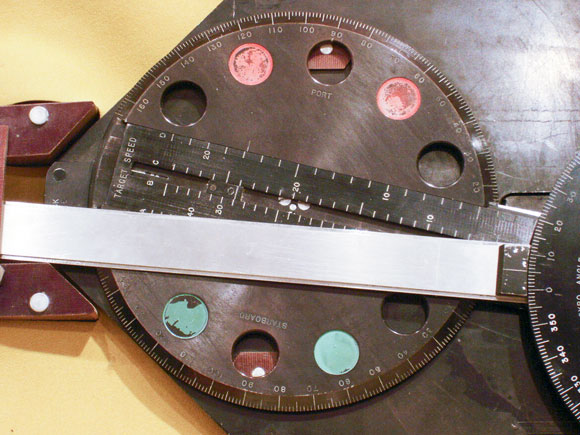
1. The Torpedo Angle Solver Mark VIII is a simple portable instrument designed to compute the required data for firing submarine torpedoes of various marks and powers at gyro angles up to 90 degrees from all classes of submarines.
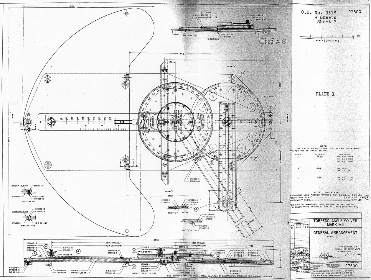
DESCRIPTION (SEE PLATE I, ORDNANCE DRAWING NO. 275001)
2. The instrument consists essentially of three arms adjustable in direction and length but so joined as to always form the basic graphic-director triangle, together with subsidiary mechanisms and scales for taking account of the curved path of a torpedo on an angle shot, the launching and running depths of a torpedo, etc. Scales are provided by means of which all quantities entering into the problem may be set or read.
3. BASE (278002-1) - The base serves as a frame to which all other parts are directly or indirectly attached.
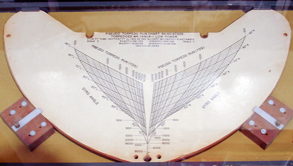
4. PSEUDO TORPEDO RUN PLATES (275007-1, 2, 3, 4, etc.)
These parts are readily
demountable plates on which the Pseudo Torpedo Run Charts are mounted, The charts on the faces of each plate are identified according to torpedo mark, power, submarine baseline and tube depth. The plates are secured to the base by means of two buttons, a tee bolt and thumb nut.
5. GYRO ANGLE DIAL (275004-1) - This part is attached
to the base by rectilinear guides and associated parts, which permit plane translation but prevent rotation of the dial relative to the base.
3
6. PERISCOPE ANGLE DIAL (275004-2) - This dial is
concentric with and rotates
on the gyro angle dial, to which it may be clamped by a thumb nut. Holes and index marks permit reading the gyro angle dial beneath.
7. PERISCOPE ANGLE ARM (275006-3) - This part is
pivoted at one and about the
center of the gyro angle dial and carries an index for reading the Periscope Angle Dial.
8. PSEUDO SPEED (275006-1) The Pseudo Speed
Arm is attached to the Gyro Angle Dial by a bearing at the dial center and is secured at the center of the Track Angle Dial in such a manner that the distance between the two dials along the arm centerline may be adjusted by sliding the arm. The Pseudo Speed Arm End (275006-2) is a transparent extension to the Speed Arm. It bears pseudo speed graduations against which the speed scales on the Pseudo Speed Scale (275005-2) are matched. The Pseudo Speed Scale is also made of transparent material. It is secured to the Pseudo Speed Arm End by means of a guide button and a thumb nut on a stud. The Pseudo Speed Scale also carries gyro angle graduations which are matched with the gyro angle lines on the Pseudo Torpedo Run Charts.
9. TRACK ANGLE DIAL (275004-3) - This part is carried on a bearing in the base and, is read at an index thereon.
10. TARGET SPEED ARM (275005-1) - This piece slides
in a tee slot in the track angle dial and bears target speed scales which are identified by letter and which are read at index marks on the track angle dial or on the Target Speed Angle Stop (275005-8). Friction springs (275005-9), beneath, prevent accidental slipping of this arm but permit ready adjustment. At one and is pivoted the Periscope Angle Arm Guide (275006-3) which engage with and slides on the Periscope Angle Arm.
11. INSTRUMENT CASE (Ordnance Drawing No, 275008) - The case will hold one Torpedo Angle Solver Mark VIII without a Pseudo Torpedo Run Plate attached and three (3) separately stowed Pseudo Torpedo Run Plates. To place the instrument in the ease proceed as follows
(a) Pull the Pseudo Speed Arm to the maximum pseudo speed and center it.
4
(b) Set track angle at zero.
(c) Note that the Pseudo Speed Arm end of the instrument fits into the case at the
and where the chocks (275009-3) are located flush with the end channel (275010-5).
(d) Insert the instrument Pseudo Speed Arm End first so that the and of the arm will rest below the flange of the case and channel, and so that the Gyro Angle Dial Rail clears the lower tee chocks (275009-5).
(e) Lock in place by sliding the latches (275009-6) toward the center of the instrument.
12. OPERATION - To operate the instrument, proceed as follows:
(a) Install a Pseudo Run Plate which corresponds to the mark and speed setting (power) of the torpedo, the baseline of the submarine and the tube depth from which it is intended to fire.
(b) Set the Periscope Angle Dial to the selected gyro angle.
(c) Select the set depth to be used and set the depth speed reduction by clamping the Pseudo Speed Scale (275006-2) to the Pseudo Speed Arm (275006-1, 2) with the corresponding value of speed reduction set opposite the index of the scale designation called for on the Pseudo Run Plate.
(d) Set the estimated target speed and the selected track angle, being sure that the scale used
5
corresponds to that called for on the Pseudo Run Plate, In setting target speed and track angle, grasp the knurled surfaces of the Periscope Angle Arm Guide (275006-3), slide the Target Speed Arm (275005-1) in the Track Angle Dial (275004-3) and then set the selected track angle against the track angle index.
(e) Hold the Track Angle Dial to its setting with one hand as the graduation of the selected gyro angle on the Pseudo Speed Arm is matched on the point on the
Pseudo Run Plate which represents the selected gyro angle and the estimated value of pseudo torpedo run.
(f) Read the firing bearing on the
Periscope Angle Dial against the
index marked on the Periscope
Angle Arm.
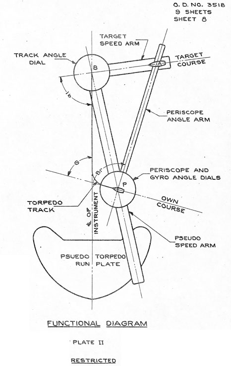
13. THEORY OF OPERATION - Since, to hit, the time of
the torpedo run and of the
target travel, to the point of intercept, must be the same,
the triangle mentioned in paragraph 2 is essentially a velocity vector triangle determined by target speed, track angle, and pseudo torpedo speed. It is represented on PLATE II by triangle ABP. Since the velocity and space triangles are similar, for purpose of visualization, P, the center of the gyro angle and periscope angle dials may be considered to be the periscope at the instant of firing; A, the center of the Periscope Angle Arm Guide, to be the target at the instant of firing; and B, the center of the Track Angle Dial, to be the point of intercept. Line PB (PLATE II) is the pseudo torpedo speed and is determined in direction and length by the Pseudo Torpedo Run Chart. Ib is track angle, G is gyro angle, and Br is relative target bearing or periscope angle at the instant of firing.
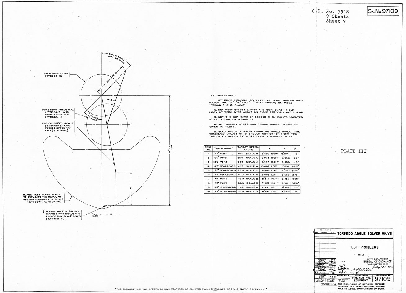
14. TESTS - Test problems and test procedure are outlined on PLATE III (Ordnance Sketch No. 97109).
6
15. MAINTENANCE - Care should be taken to keep the
instrument clean, dry and free of corrosion and abrasive particles. Lubricate all pivots and slides with a light coating of petrolatum.