Torpedoes Mark 14 and 23 Types, OP 635, 1945, is the basic service manual for the principle U.S. torpedo of WW II. It is also shows all the key elements of a successful steam torpedo and represents the peak of U.S. WW II torpedo technology.
In this online version of the manual we have
attempted to keep the flavor of the original layout while taking advantage
of the Web's universal accessibility. Different browsers and fonts will cause
the text to move, but the text will remain roughly where it is in the original
manual. In addition to errors we have attempted to preserve from the original
this text was captured by optical character recognition. This process creates errors that are compounded while encoding for the Web.
Thank you Robert Forscutt for the opportunity to scan this manual.
Please report any typos, or particularly annoying layout issues with the Mail Feedback Form for correction.
NAVY DEPARTMENT BUREAU OF ORDNANCE WASHINGTON 25, D. C.
12 JANUARY 1948
To all holders of OP 635(1st Rev),OP 642(1st Rev),OP 946 (2nd Rev)
insert change; write on cover 'Change inserted'
Approved by The Chief of the Bureau of Ordnance
OP 635 (1st Rev) Change 3
OP 642 1st Rev)) 1
OP 946 2nd Rev Change 1
1 Page _____ Page 1
OP 635 (1st Rev) -- TORPEDOES MARK 14 AND 23 TYPES
OP 642 (1st Rev) -- TORPEDOES MARK 15 TYPE
OP 946 (2nd Rev) -- TORPEDO MARK 18 MOD 2
are changed as follows:
1. Preceding paragraph one in:
OP 635 (1st Rev), Chapter 7, Section 3, Page 120
OP 642 (1st Rev), Chapter 7, Section 3, Page 123
OP 946 (2nd Rev), Chapter 10, Section 3, Page 191
add:
WHEN PERFORMED. These tests shall be performed within 72 hours of firing a torpedo.
2. Insert this instruction sheet ahead of title page of pamphlet.
DISTRIBUTION
Requests for additional copies of OP 642 1st Rev (Change 1), OP 675 (Change 3) and OP 946 2d Revision(Change 1) should be submitted on NavExos 158 (formerly NavGen 47), Stock Forms and Publications Requisition, through the District Publications and Printing Office by which addressee is serviced. Mailing addresses may be obtained from List 10.VV of the Standard Navy Distribution List.
Standard Navy Distribution List No. 49 (Part 1) and Edition 7o, 7 (Part 2) to Catalog of Activities of the Navy.
Requests for additional copies of OP 635 (1st Rev.) Change 1 should be submitted on NAVORD FORM 1, ORDNANCE PUBLICATIONS AND FORMS REQUISITION, to the nearest Ordnance Publications Distribution Center: U.S. Naval Gun Factory, Wash. 25, D.C.; Mare Island, Calif.; Pearl Harbor T.H. Distribution Center mailing addresses should be obtained from List 10nn of the Standard Navy Distribution List, or from the reverse side of NAVORD FORM 1.
Standard Navy Distribution List No. 35 (R)
2 copies unless otherwise noted.
1.
a, f, h, i, j, l
2.
j*, u
3.
bbbb, eeee
5.
b(London only)
7.
f, h, k*, q*, x*, y*
7.
(5 copies), b*, c*, 1*, p*
7.
(10 copies), a*
8.
n (SPECIAL LISTS F, X), y
10.
f*, m*, hh, nn, ss
11.
a (CNO)
12.
a, b
13.
c(3), (4), (6)
*Applicable addressees.
RESTRICTED
NAVY DEPARTMENT BUREAU OF ORDNANCE WASHINGTON 25, D. C.
To all holders of ORDNANCE PAMPHLET 635 (FIRST REVISION)
insert change; write on cover 'Change 2 inserted'
Approved by The Chief of the Bureau of Ordnance
OP 635 CHANGE 2
(1st Rev.)
29 April 1946
1 Page ____ Page 1
ORDNANCE PAMPHLET 635 (FIRST REVISION)
is changed as follows:
TORPEDOES MARK 14 AND 23 TYPES
Page 167, Par. T, Step 6, add, "Note: If torpedo is to be used in exercise firing do not install ring seals".
Insert Change 2 instruction sheet after Change 1 before title page.
DISTRIBUTION
Requests for additional copies of OP 635 (let Rev) Change 2 should be submitted on NAVORD FORM 1, ORDNANCE PUBLICATIONS AND FORMS REQUISITION, to the nearest
Ordnance Publications Distribution Center: U. S. Naval Gun Factory, Wash. 25, D. C.; Mare Island, Calif.; Pearl Harbor, T. H. Distribution Center mailing addresses should be obtained from List 10 nn of the Standard Navy Distribution List, or from the reverse side of NAVORD FORM 1.
DISTRIBUTION:
Standard Navy Distribution List No. 36 (R)
2 copies unless otherwise noted.
This publication is RESTRICTED and shall be safeguarded in accordance with the security provisions of U. S. Navy Regulations, 1920, Article 76.
This page blank.
3
BUREAU OF ORDNANCE
NAVY DEPARTMENT
WASHINGTON 25. D. C.
24 March 1945
RESTRICTED
ORDNANCE PAMPHLET 635 (FIRST REVISION)
TORPEDOES MARK 14 AND 23 TYPES
1. Ordnance Pamphlet 635 (First Revision) explains the construction and operation of Torpedoes Mark 14 and 23 Types, and contains complete information on the adjustments, overhaul, and tests required after the torpedo has been accepted for issue by the service.
2. This pamphlet supersedes Ordnance Pamphlets 635 and 635A, and Ordnance Data 3834 (Revision A) and 3842 (Revision A), which should be destroyed.
3. Detailed information is given for the gyroscope in Ordnance Pamphlet 627A, and for the exploder mechanism in Ordnance Pamphlets 663 and 663A. Information on workshop equipment and its use may be found in Ordnance Data 750.
4. This publication is RESTRICTED and shall be safeguarded in accordance with the security provisions of U. S. Navy Regulations, 1920, Article 76.
G. F. HUSSEY, JR.,
Rear Admiral, U. S. Navy, Chief of the Bureau of Ordnance
This ordnance pamphlet describes and illustrates the most essential details of construction, handling, and operation of the Torpedoes Mk. 14 and Mk. 23 Types. These torpedoes are designed for launching from submarines, but they may also be launched from surface craft. A careful study of this pamphlet, and consultation with qualified personnel when uncertainties arise, will give the beginning student a sufficient knowledge of the fundamentals. Such knowledge, combined with common sense and mechanical ingenuity, will make it possible for the torpedoman to perform satisfactorily all the service operations that are required for the maintenance, adjustment, and tests of these torpedoes.
The Torpedoes Mk. 14 and Mk. 23 Types,
for all their size and weight, are carefully and delicately constructed. Each torpedo, therefore, should be given the care and respect due all valuable machines.
Mistakes in the handling and servicing of torpedoes can be too costly-in lost opportunities for the destruction of enemy vessels, in the loss of lives of our own men in the service, and in money wasted-to excuse reluctance or failure to seek accurate information from those who are qualified to supply it. Slighting one step in the servicing of a single torpedo may result in that torpedo missing its target, and the armament of that missed target may cause destruction and loss of life in our own fleet. That thought should be kept constantly in mind while studying this pamphlet, and when handling or servicing torpedoes.
8
What is a Torpedo?
A torpedo is a self-propelled, underwater weapon, designed to carry an explosive charge to an enemy vessel and destroy it. It is equipped with mechanical devices that automatically generate the power to drive it, and other devices that control its direction, its speed, and the depth at which it will travel in the water, once it has been launched.
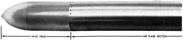
The torpedo consists of four major exterior sections, each of which will be more fully described later. They are: (a) the head; (b) the air-flask section; (c) the afterbody, and (d) the tail. There are two types of heads: the war head and the exercise head. The war head contains the explosive charge and is used in combat. The
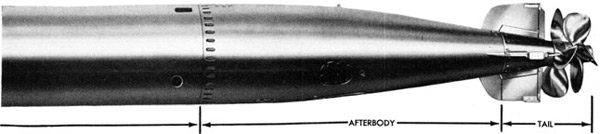
exercise head is used for test runs and target practice. The air-flask section stores the supply of air, fuel, and water required to operate the propelling and controlling mechanisms that are contained in the after-body. The tail includes the propellers and the rudders.
The propelling and controlling mechanisms of the afterbody are set in operation as follows: As the torpedo is fired from the tube, the forward motion of the torpedo causes the starting lever to be thrown aft by the tripping latch. This action of the starting gear allows the air to flow from the stored-up supply in the air flask to all the operating mechanisms. The operating mechanisms then propel and control the course of the torpedo to its target.
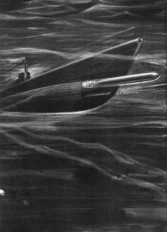
Figure 1-Torpedo Mk 14 Type with War Head, side view
9
Chapter I
GENERAL DESCRIPTION
THE SECTIONS AND THEIR OPERATION
As already stated, a complete torpedo consists of four major units or sections, comprising the head (war or exercise), air flask, afterbody, and tail; see Figs. 1 and 2. All these units or sections of the torpedo are described in the following chapters of this pamphlet. A brief general description of each is given here, however, so their relationship may be more clearly understood. In connection with these general descriptions, readers should refer to the illustrations (figures) in the text.
War Head
The war head (Figs. 4 and 5) is the business end of the torpedo. It carries an explosive charge of either TNT or Torpex, and also the firing device (exploder mechanism) which detonates the explosive at the target.
Excercise Head
All torpedoes are given a trial or exercise run before being sent into service. Target practice is necessary, moreover, for training and improving the skill of personnel. The exercise head (Fig. 9) is used as a
substitute for the war head in trial runs and in target practice.
This head has the same dimensions and trim characteristics as the war head, except that it is made of steel instead of phosphor bronze. Instead of the explosive charge and the exploder mechanism, it carries liquid ballast. It is so constructed that the liquid ballast is expelled at the end of the run, being forced out by air from the air flask. The air replacing the liquid ballast gives the torpedo buoyancy, which causes it to float to the surface, thus permitting recovery.
Air-Flask Section
The air-flask section (Figs. 2, 18, and 19) consist of the air compartment, the water compartment (which also contains the fuel flask), and the midship section. The air compartment carries highly compressed air, which, combined with fuel (alcohol) and water, provides the energy to drive the mechanisms which propel and guide the torpedo. The air compartment is a storage tank for high-pressure air, and is located directly abaft the war or exercise head as
Figure 1-Torpedo Mk 14 Type with War Head, side view
10
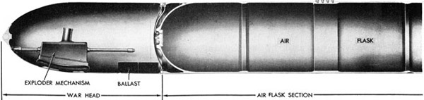
Figure 2-Cross-section view of Torpedo Mk 14 Type, showing location of interior mechanisms
shown in Fig. 2. The combination of the air compartment, the water compartment, the fuel flask, and the combustion flask, may well be termed the "boiler room" of the torpedo.
Midship Section
The midship section is riveted and soldered to the after end of the water compartment of the air-flask section. Its after end, in turn, is machined to form a joint with the afterbody. The parts in this midship section do not require the exclusion of water from their exterior surfaces. Furthermore, the parts which convey hot gases must be externally cooled in order that they may not be injured by the interior temperature. Also, access to certain other parts must be provided to permit adjustment or manipulation. Provision is made, therefore, for free circulation of sea water in the midship section, and for access to parts contained therein, by making openings in the shell.
The shell is clearly marked (Fig. 27), indicating access to the parts and valves which are described in Chapter 3, "The Air Flask Section."
Afterbody
The afterbody, which is abaft the air-flask section, may be termed the engine room of the torpedo, in that it is the housing for the propelling and controlling mechanism (Fig. 32). Attached to the forward bulkhead of the afterbody is the combustion flask, in which are formed the gases and steam for the turbines which supply the
driving force for the torpedo's two propellers. The afterbody contains the depth mechanism, which, with its depth engine and depth rudders, maintains the torpedo at its set depth. It also contains the gyroscope with its related mechanism which, in conjunction with the steering engine and steering rudders, maintains the torpedo on its course.
Tail
Abaft the afterbody, and completing the torpedo assembly, is the tail section (Fig. 64A). This section carries the tail blades and the depth and steering rudders, which maintain the torpedo's depth and course,
and also the two propellers which propel it through the water.
The propellers revolve in opposite directions, one clockwise and the other counterclockwise, so that the torque or turning power of the one counteracts that of the other. A single propeller would tend to make the torpedo itself revolve in the water, making it difficult or impossible to control its course and depth.
How the Torpedo Operates
As has been stated, the torpedo is equipped with mechanical devices which make it self-propelling after it is launched. While these devices will be described in detail in the pages following, a general overall idea of how they operate may be gained from the schematic diagram shown here (Fig. 3), with the accompanying explanation.
11
Figure 2-Cross-section view of Torpedo Mk 14 Type, showing location of interior mechanisms
It must be clearly understood that the schematic diagram does not show the various operating mechanisms in their actual positions, or even in their relative positions. The mechanisms have been reproduced photographically with a view to showing them in sufficient detail to make them readily identifiable when seen in their proper positions in the torpedo or when removed from the torpedo.
Furthermore, the schematic diagram may show several parts separately, whereas those parts may actually be contained in one body or in one mechanism. Also, it should be understood that the action of all parts is practically simultaneous once the starting gear has been tripped and the operating mechanisms set in action.
Only the air flask and the afterbody are shown in the schematic diagram. When a war head is attached, there is no air connection from the war head to the air flask. When an exercise head is attached, however, the air is connected at the blow valve, which is located at the forward end of the air flask, thereby allowing the air to flow to the air-releasing mechanism in the exercise head, as is more fully explained in the chapter dealing with the war and exercise heads (Chapter 2, Section 2).
Referring to the schematic diagram (Fig. 3): High-pressure air is stored in the air flask. It is fed through the stop and charging valve, through the preheater, then through a small orifice in the starting valve of the starting and reducing valve group, and to the piston of the starting gear. The
air is held under high pressure between the air flask and the starting-gear piston until the torpedo is launched.
As the torpedo is fired, the starting lever is thrown aft by the tripping latch in the tube, and this action lifts the starting piston off its seat. As the starting piston is lifted, the high-pressure air banked up over the starting valve is released, thereby allowing the starting valve to lift. As the starting valve lifts, the air passes to all the operating mechanisms of the torpedo.
Part of the high-pressure air is diverted to the gyro spinning mechanism, and part to the control chamber of the reducing valve. The bulk of the high-pressure air entering the reducing-valve chamber passes through the reducing valve, where the air is reduced from flask pressure to approximately 450 p.s.i. (pounds per square inch). This reduced-pressure air is then distributed by three branches: (a) to the air checks; (b) through the restriction valve to the combustion flask; and (c) to the igniter.
From the air checks, the low-pressure air flows to the water compartment and to the fuel flask, forcing the water and fuel through pipes to the water and fuel strainers and check valves. The fuel and water then pass through their respective restrictions in the restriction valve and to the fuel and water sprays in the combustion flask. The main supply of the reduced-pressure air passes through the air restriction in the restriction valve and to the combustion flask.
12
Figure 3-Schematic Diagram, Torpedoes Mk 14 and Mk 23 Types, showing flow of air to operating mechanisms (see explanation in descriptive text)
The reduced-pressure air also fires the igniter, which ignites the fuel in the combustion flask, where the combination of fuel, air, and water is converted into gases and steam at a high temperature and fed through a pipe to the nozzles of the turbines, furnishing the power for propelling the torpedo.
Air passes from the top of the combustion flask and from the control valve to the air-strainer body. From the air-strainer body, this air flows through two branches. One branch leads to the steering engine and through the gyro reducer to the gyro (which is inside the gyro pot) where it sustains the spin of the gyro. The other branch leads from the air-strainer body to the depth engine.
As the torpedo is launched, its initial dive takes it below its pre-set depth. The depth mechanism brings it back to set depth, and maintains it at this depth by means of the depth rudders. The steering rudders, operated by the gyro mechanism,
keep the torpedo on its predetermined course to the target.
As the torpedo runs through the water, a small impeller on the under side of the
war head rotates, arming the exploder mechanism, and putting it in condition to be fired when it reaches the target.
Should the torpedo miss the target, it will run its course until its power is exhausted and then sink to the bottom.
When fitted with an exercise head, a connecting pipe leads from the air flask to the air-releasing mechanism in the upper part of the exercise head. When the air flask pressure has fallen below the pressure setting on the air-releasing mechanism, a valve in the mechanism is opened, allowing the air to enter the exercise head and force the water out through water discharge valves in the bottom of the head. The air replacing the water in the exercise head gives the torpedo positive buoyancy. This causes the torpedo to float, so it can be retrieved.
13
Figure 3-Schematic Diagram, Torpedoes Mk 14 and Mk 23 Types, showing flow of air to operating mechanisms (see explanation in descriptive text)
Buoyancy
A torpedo is said to have positive buoyancy when it has a tendency to rise to the surface; it is said to have negative buoyancy when it has a tendency to sink. The buoyancy of a torpedo in water depends upon the ratio of its weight per unit volume as compared to the weight per unit volume of water.
The three factors which affect the buoyancy
of a torpedo are: (a) the displacement (volume); (b) the fixed (not expendable) weight; and (c) the expendable weight. The air, the water in the water compartment, and the fuel are expended in proportion to the length of the run. The water ballast in the exercise head is expended at the end of the run. If a sufficient amount of weight is expended, the torpedo will obtain positive buoyancy and will finish its run on the surface. The buoyancy of the torpedo will, of course, be adversely changed by salt water leakage into the afterbody and the exercise head. A table of approximate buoyancy
factors will be found in the appendix at the back of this pamphlet.
Marks and Modifications
The designations Mk 14 Mod 3A, or Mk 14-3A, Mk 23, etc., apply only to the complete torpedoes, including the afterbody and the tail. Each type of war or exercise head, also the gyroscope and the exploder mechanism, are given individual designations, as will be described in the chapters referring to those parts. Usually, when changes or improvements are made in any part of a torpedo, the changed torpedo is given either a modification number or a change in Mark.
For example, the depth mechanism of the Torpedo Mk 14-3 was improved, and the torpedo was designated the Torpedo Mk 14-3A. The Torpedo Mk 14-3A was then changed to a single high-speed torpedo, and it was given the designation Mk 23.
The Torpedoes Mks 14, 14-1, 14-2, and 14-3 are out of service. The Torpedo Mk 14-1A is a two-speed torpedo, with speeds
14
of 31 and 46 knots, having a range of 9,000 yards and 4,500 yards respectively. The gyro mechanisms provide for angle shots up to 90 degrees right or left.
The Torpedo Mk 14-3A has the same speed and range as the Mk 14-1A, but the gyro mechanism provides for angle shots up to 160 degrees.
The Torpedo Mk 23 is a Torpedo Mk 14-3A in which the speed-change mechanism has been removed, leaving all five nozzles open. The restriction valve is locked in high power, and thus the engine is operated at high speed only.
The Torpedo Mk 23-1 is a Torpedo Mk 23 in which the restriction valve body is drilled to provide air, fuel, and water passages for high speed only.
Interchangeability
All assembled units and mechanisms in the torpedo are interchangeable in the Mark and Modifications to which they are assigned. In general, all detail parts are also
interchangeable except for special assembling operations, such as lapping of pistons, doweling, etc.
Identification Numbers
The register number is the torpedo identifying number. All others are serial numbers which identify some part or unit of the assembly. The register number is stamped in three places: (a) on the flask near the forward joint line; (b) on the afterbody near the forward joint line; (c) on the tail.
In the past, serial numbers were given to each of the following units: (a) the exercise head; (b) the war head; (c) the air flask; (d) the afterbody; (e) the gyro; (f) the tail. Newly manufactured torpedoes will hereafter bear the register number only, marked on the air flask, afterbody, and tail. Gyros, exploder mechanisms, exercise heads and war heads will bear serial numbers; boosters, detonators, and igniters will bear lot numbers, date, and place of manufacture.
15
Chapter 2
WAR AND EXERCISE HEADS
SECTION 1 - THE WAR HEAD
Figure 4-War Head Mk 16-4-Cut-away view
The war head is the torpedo's reason for existence. It is the "business end" of the torpedo, since it carries the explosive charge
and the exploder mechanism which detonates it. The other sections of the torpedo merely comprise the vehicle for carrying the war head to its target.
Normally the war head, fitted with a protecting ring on its joint ring, is stowed with the exploder mechanism removed, and requires relatively little attention other than routine inspection. In time of war, however, when torpedoes are kept in the "fully ready" condition for extended periods of time, the servicing routines prescribed for the war head and its attachments must be rigidly followed.
The war heads provided for the Torpedoes Mk 14 and Mk 23 Types are the War Heads Mks 16, 16-1, and 16-4.
All the war heads are ogival in contour at the forward end, and cylindrical in form at the after portion. A nose piece secured to the forward end of the shell is provided to facilitate handling of the war head. The war-head shells are made of phosphor bronze in order to provide for more effective operation of the magnetic feature of the exploder mechanism.
The joint ring, attached to the after end of the head, is drilled and tapped for the joint screws used to attach the head to the air flask. The joint ring is also flanged for a steel bulkhead, dished in form, which is
16
Figure 5-War Head Mk 16 Type-Exterior View, bottom
bolted to it, and which, with a rubber gasket, forms a water-tight closure for the after end of the head. Three reinforcing plates cover the breaking tool holes when the bulkhead is installed to prevent sea water leakage through these holes. The bulkhead is fitted with a test connection.
All of the war heads have a metal shell, called the exploder casing, secured to the top of the exploder-mechanism mounting flange. The casing is so shaped that it closely fits the contour of the exploder mechanism, and a cylindrical projection at its top provides a housing for the booster and safety chamber.
Each end of the exploder casing is fitted with a metal tube. The axes of the tubes are in line with each other and parallel to the center line of the war head. These tubes are provided as a housing for the exploder-mechanism core rod, which projects beyond the ends of the exploder casing. The forward core-rod tube is also secured to a fitting on the war-head shell. This fitting is closed by a plug which, when removed, allows insertion or removal of the core rod. A filler piece screwed to the plug fills the hole in the war-head shell and completes the smooth surface of the war head.
When the exploder mechanism is screwed to its flange with a gasket between the exploder base and the flange, the exploder casing and the exploder base form a water
tight chamber within which the exploder mechanism functions.
For transportation and stowage, a cast-iron protecting ring and an exploder-mechanism dummy block, or a sheet-metal cover which closes the exploder cavity, are provided with each war head in service. The
protecting ring is secured to the joint ring with six joint screws, the purpose being to protect the joint ring against damage. The wooden exploder-mechanism dummy block, or the sheet-metal cover, when secured to the flange with four screws, protects the exploder-mechanism mounting flange in the head against damage.
Explosive Charge
The war head contains a charge of high explosive, either TNT or Torpex, which is poured into the shell in the molten state.
War heads loaded with Torpex have a small charge of TNT in the nose of the head, and the War Heads Mk 16-1 and Mk 16-4 have a "topping charge" of TNT which fills the space between the after end of the Torpex charge and the after bulkhead of the war head. The War Head Mk 16, when loaded with Torpex, has a cavity in the after end of the charge in order to give the war head proper trim characteristics.
In all the war heads, the center of gravity is below the center line of the head in order to give the proper "pull around" stability
17
Figure 6-Exploder Mechanism Mk 6-5
to the head, thereby tending to reduce rolling tendencies of the torpedo when the torpedo is traveling through the water. (The weights and compositions of explosive charges for the various war heads are given, together with other statistical data, in the Appendix at the back of this pamphlet.)
Exploder Mechanism
The exploder mechanism shown in Fig. 6 is an indispensable part of the war head, since it is the device which detonates the explosive charge when the torpedo reaches its target.
War heads for the Torpedoes Mk 14 and Mk 23 Type are fitted with Exploder Mechanisms Mk 6 Mod 5, which are fired by direct impact with the target.
The exploder mechanism is mounted on a flange in a rectangular cavity (exploder-mechanism casing) in the forward part of
the war head. The exploder-mechanism base
is rectangular in shape to fit the war head cavity, and its exterior surface is curved to maintain the contour of the head.
A channel in the exploder mechanism
base provides a path for the stream of water that drives the impeller wheel which furnishes the driving power for the various mechanisms within the exploder mechanism (Fig. 6A). The rotation of the impeller is transmitted to the interior of the exploder-mechanism base by means of a shaft passing through a watertight packing gland.
A direct-current generator driven from the impeller shaft supplies the electrical energy necessary for firing the detonator. A voltage regulator tube controls the output of this generator, limiting it to a nearly constant value, regardless of the speed of the generator. This generator charges a large condenser, which then becomes a reservoir of electrical energy. When this energy is released by closing an impact switch, it fires the detonator and detonates the war head.
When the torpedo is fired, the exploder mechanism must be inoperative for the first part of the run in order to protect the firing vessel from possible premature action of
the run and within which it can be fired without detonating the war head.
2. The delay device, composed of a switch which grounds the generator of the exploder mechanism during the first part of the run, thus temporarily preventing current from passing into the condenser and detonator.
A self-cocking impact-operated switch provides the means for firing the detonator upon impact of the torpedo with the target. This impact switch is installed in the exploder-mechanism casing above the exploder mechanism, and is connected by wire leads to the electric terminals of the condenser and the detonator, which are mounted in the exploder-mechanism base.
The operation of the exploder is as follows:
Upon launching of the torpedo the impeller of the exploder begins to rotate. The rotation of the impeller drives a gear train (Fig. 7A) which rotates the delay-device worm wheel and the arming gear. The delay device renders the generator inoperative by grounding its field circuit until the delay wheel has made nearly a complete revolution, at which time the wheel stops, breaking the ground, thus activating the field circuit and allowing the generator to build up operating voltages. In the meantime the rotation of the arming gear has run the detonator up out of the safety chamber into the booster cavity (firing position). The generator charges the large condenser, mounted on the firing-mechanism base plate, which supplies the electrical energy necessary for firing the electrical detonator.
Upon impact with the target, the ball in the impact switch (Fig. 8B) is displaced,
and as a result the spring contact of the switch is forced down, making electrical contact with the fixed contact. As soon as electrical contact is made, the condenser is discharged through the electric detonator (Fig. 8A), setting it off, thus detonating the booster and the main charge in the war head.
Note: The exploder mechanisms are issued to the service with a pick-up coil and thyratron tube installed on their base. These devices are applicable to the influence feature only and will not be described in this publication.
Booster
Above the exploder mechanism, when installed in the war head, is a thin sheet-copper container holding a charge of tetryl. This is known as the booster. It is so shaped that it fits inside the pocket at the top of the exploder casing, and rests snugly upon the top of the safety chamber.
The detonator, during the arming operation, is moved up out of the safety chamber into a recess in the bottom of the booster; thus, the detonation of the detonator can set off the booster. Before the exploder is fully armed, the detonator holder is within the safety chamber, where it can explode without detonating the booster. It is not until the detonator holder is well extended from its safety chamber that it can detonate the booster; thus any accident which might cause the detonator to explode while the torpedo is still aboard, or close to its firing vessel, cannot cause detonation of the war head, since the torpedo must travel about 350 yards through the water before the detonator can fire the booster.
20
Figure 9-Exercise Head Mk 30-4-Cut-away view, including the various
parts which assemble into it
21
Chapter 2 - Section 2
THE EXERCISE HEAD
General Description
All torpedoes must be given a proving run before being sent into service. In addition, target practice is essential for training purposes and for perfecting skill in launching torpedoes. Therefore, the exercise head has been designed to replace the war head when a torpedo is being given a proving run or is being used for target practice.
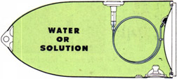
The exercise head, shown in cut-away in Fig. 9, is similar to the war head in general appearance. It does not carry the explosive charge, however; and only the Exercise Heads Mk 30-2 and Mk 30-3, which are used for special purposes, carry the exploder mechanism. Water ballast, or a chemical solution, is used in the exercise head to obtain trim characteristics similar to the war head.
The exercise head is so designed that, as the torpedo nears the end of its run, the liquid ballast is expelled by air forced into the head from the air flask.
The expulsion of ballast makes the torpedo buoyant, thus causing it to rise to the surface, where it floats until retrieved.
Exercise Head Details
The exercise head, shown in Fig. 9, has the same dimensions and trim characteristics as the war head. It contains the air-releasing mechanism, by means of which air for expelling the water ballast is admitted at the end of the run; the discharge valve (or valves), through which the liquid ballast is expelled; the torpedo headlight, which is used for night practice; and the torch case, which contains chemicals that burn when in contact with water. The torch, however, should not be used when firing from submarines, because of the possibility of premature ignition and consequent emission of dangerous fumes within the ship.
Exercise heads designated for the Torpedoes Mk 14 and Mk 23 Types are the Exercise Heads Mks 30, 30-1, 30-2, 30-3, and 30-4. The shells for the Heads Mks 30, 30-1, and 30-4 are drawn steel, with ogival nose sections and cylindrical after portions. The shell for the Exercise Heads Mk 30-2 and Mk 30-3 differs from the Heads Mk 30, 30-1, and 30-4, in that it is made of phosphor bronze, and is fitted for installation of an exploder mechanism and a device known as the "marker bomb", which will be described later.
Figure 10A-Exercise Head-Water-Expulsion Feature-Ready for a Run
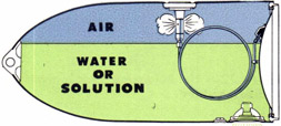
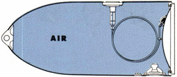
Figure 108-Exercise Head-Water-Expulsion Feature-Water being expelled
The air-releasing mechanism, as shown in Figs. 10A, 10B, and 10C, also 11A and 11B,
operates by falling rather than by increasing air pressure. The valve may be set so the air-releasing spring will expand against air pressure ranging from 600 to 400 p.s.i.
Compressed air at flask pressure holds the valve on its seat until, as the torpedo completes its run, the pressure in the flask drops to the pressure for which the air-releasing mechanism is set. At this pressure, the air-releasing spring expands and, in so doing, opens the valve, thereby allowing air from the air flask to pass through the escape ports into the exercise head, as shown in Fig. 11B.
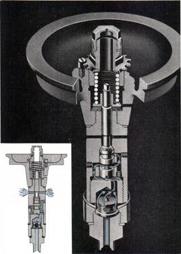
The Air-Releasing Mechanism Mk 3, shown in Fig. 11A, is automatic, the valve being cocked when air at full flask pressure is admitted to the air-releasing mechanism. In the Air-Releasing Mechanism Mk 2, the valve must be cocked by hand; otherwise the operation and adjustment are the same as with the Mechanism Mk 3. The method of cocking the Mechanism Mk 2 is given in the chapter on adjustments and tests.
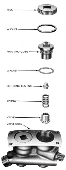
The parts of the Air-Releasing Mechanism Mk 3 disassembled are shown in Fig. 12. Studying these parts and comparing them with the cut-away views shown in Figs. 11A and 11B gives a clearer understanding of the construction and operation of the air-releasing mechanism.
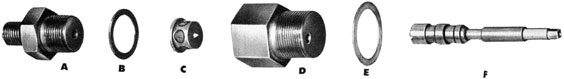
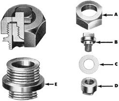
Figure 12-Air Releasing Mechanism Mark 3, disassembled.
A. Restriction nipple: Receives pipe leading in air from air flask also serves as rest for strainer C.
B. Washer: Fits between parts A and D.
C. Strainer: Prevents entrance of grit or other solid matter into valve passages.
D. Strainer holder: Shoulder of strainer C
rests against machined seat in strainer holder; hole drilled off center in strainer holder body conveys air into valve casing
E. Washer: Fits between parts D and G.
F. Valve, valve stem and pistons: Machined in one piece, this inserts into valve casing G, and engages air releasing spring support.
23
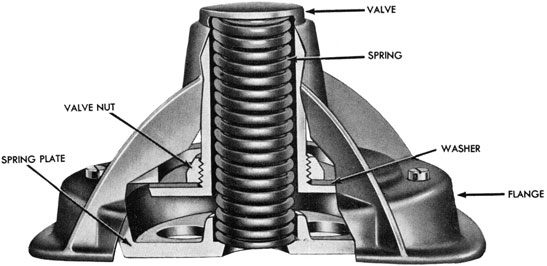
Figure 13-Discharge Valve, Cut-away view
Discharge Valve
The discharge valve (Fig. 13) is located as shown in Fig. 9. The valve operates automatically, opening when the pressure inside the exercise head exceeds the combined spring and external water pressure holding the valve closed. In other words, when the air pressure in the air flask falls to the set pressure, the air-releasing mechanism
admits air into the exercise head, and the resulting pressure in the head forces the discharge valve open.
The valve opens outwardly, expelling the liquid ballast, and closes when the ballast has been entirely expelled and the air pressure in the exercise head has dropped below the minimum necessary to hold the valve open.
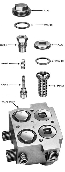
Figure 12-Air Releasing Mechanism Mark 3, disassembled.
G. Valve casing: See Fig. 11A for interior construction. Upper and lower portions are screwed and sweated together and are treated as one unit. (note: Beveled seat on under side of valve casing is undercut to hold gasket in alignment. Centering ring shoulders against flange, preventing canting of valve.)
H. Air releasing spring support: Flanged end rests against shoulder on valve stem "F."
I. Air releasing spring: Compression type; may be installed with either end based on air releasing spring support.
J. Adjusting nut: Turns to right or left to increase or decrease compression of air releasing spring "K" through pressure range from 600 to 400 pounds.
K. Adjusting nut lock screw: Must be backed out entirely before nut "J" can be turned, and replaced firmly when adjustment is completed.
L. Washer: Fits between part "J" and "M."
M. Adjusting nut cap: protects valve stem "F" from accidental handling or damage, and is vented to prevent banking up of any air which may pass valve stem; also vents water due to expansion.
24
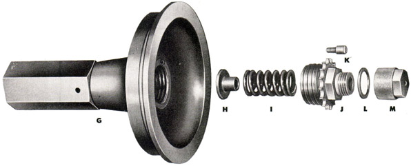
Torpedo Headlight
The torpedo headlight (Fig. 14) is designed for use in night practice. It is located as shown in Fig. 9, when used.
The switch is operated by an inertia weight, one end of which is pivoted on the
Figure 14-Torpedo Headlight
base plate. The free end in contact with the free end of the switch lever keeps the switch open until actuated by the inertia of the torpedo upon launching, at which time the weight is swung clear of the switch lever and the spring closes the switch, thereby lighting the headlight.
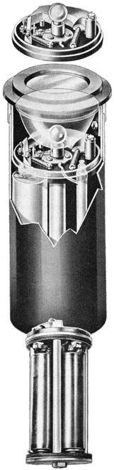
Figure 15-Torpedo Torch
Torpedo Torch
The torpedo torch (Fig. 15) is used in daytime practice. It contains calcium phosphide, which burns when it becomes mixed with water. This chemical is in a container having a small hole in the upper side, the hole being sealed with a tin strip soft-soldered in place and having a ring for use in removing it. The torch is placed in the torch case, located as shown in Fig. 9. Just before placing the torch in the case, the tin seal on the top is removed, thereby permitting the entrance of water after the torpedo is launched.
Caution: Great care must be taken in handling to insure against contact of the chemicals with moisture.
War Exercise Head
The war exercise head (Fig. 16) is used for experimental and instructional activities where the operation of the exploder mechanism is to be demonstrated. The head shell is fitted with an exploder mounting flange
25
Figure 16-War Exercise Head Mk 30-3, Cut-Away View
and casing similar to those in a war head, with the exception that the exploder casing is necessarily heavier because of the pressure built up in the head when it blows.
In the booster cavity of the exploder casing, a switch, operated by the firing pin of the exploder mechanism, is installed.
When the exploder mechanism fires, its firing pin closes the switch, thus allowing current from two flashlight batteries to flow to the marker bomb, causing it to fire. When exploders using electric detonators are used in the war exercise heads, the marker bomb is connected into the exploder circuit in
Figure 17-Marker Bomb for Exercise Head Mk 30-2 or Mk 30-3, Cut-Away View
26
place of the electric detonator. In this case, the switch in the booster cavity and the flashlight batteries are not needed.
Marker Bomb
The marker-bomb body (Fig. 17) consists essentially of a heavy steel cylinder, which fits into the forward accessory flange in the war exercise head, as shown in Fig. 16. On the lower end of the cylinder is a nipple housing the explosive cartridge, which is exploded by the current sent to the marker bomb when the exploder mechanism fires. The leads from the cartridge are led
out of the marker bomb through watertight rubber packing compressed under a screw cap on the end of the nipple. The upper portion of the marker-bomb body contains a series of plywood discs held in place by a lead disc secured to the outboard end of the body by a ring nut.
When the exploder mechanism fires, it causes the marker-bomb cartridge to explode. The explosion of the cartridge shears the lead disc and drives the plywood discs out of the body, after which they rise to the surface and float, marking the spot at which the exploder mechanism fired.
27
Chapter 3
THE AIR-FLASK SECTION
Figure 18-Air Flask Section, sectional view, showing in colors where the air (blue), water (green), and fuel (red) are stored
General Description
The air-flask section (Figs. 18 and 19), combines the air compartment, the water compartment and fuel flask, and the mid-ship section. It is the main body of the torpedo, and may be called the "boiler room" of the torpedo. Herein are contained the compressed air, the fuel, and the water, which release the energy necessary to drive the mechanisms which propel and guide the torpedo.
The forward, and by far the greater, portion of the air-flask section (see Fig. 18) is in reality a storage tank for high-pressure air. Air alone, however, can not propel the torpedo for any useful distance at a sustained speed; but by combining the air with a highly volatile fuel and with water, in predetermined proportions, a gas and steam mixture is produced, which provides sufficient energy to propel the torpedo at its designated speed and range.
Immediately adjoining the air compartment, at its after end, is the water compartment, which also contains the fuel flask.
The midship section consists of the portion at the extreme after end of the air-flask section, where the air-flask section joins the afterbody, as shown in Fig. 18. This midship section provides a space for housing and cooling the parts which convey the hot gases to the turbines to supply the power for propelling the torpedo. Openings are provided in the midship-section shell
for access to and adjustment of the parts therein.
The flow of air, water, and fuel from their respective compartments in the air-flask section to the operating mechanisms which are contained in the afterbody of the torpedo, is shown in the schematic diagram, Fig. 3, on pages 12 and 13.
Air-Flask Section Detail
The air-flask section is cylindrical in shape, and of uniform outside diameter throughout its length. However, a smaller inside diameter at the guide stud location provides the necessary additional thickness
28
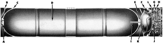
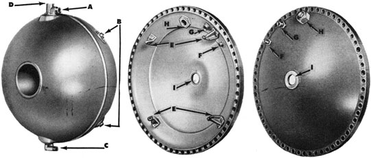
Figure 19-Air-Flask Section, cut-away view, showing positions of the various fittings: (A) Small forward bulkhead; (B) Blow valve; (C) Air vent; (D) Air compartment; (E) Water compartment; (F) Filling hole; (G) Stop and charging valve; (H) Air check valves; (I) "Dry" pipe; (J) Main air pipe; (K) Fuel flask; (L) Fuel and water strainers and check valves
of the shell at this point for launching support.
The air flasks are of two types: the forged flask and the welded flask. The welded type is now being manufactured exclusively.
The forged air flask is a cupped and drawn alloy steel forging, cylindrical in shape. To its after end is riveted and soldered the midship section, which thus becomes an integral part of the air-flask section. The welded air flask is made up of several forgings welded into a unit. The midship section is riveted and soldered to the after end of the air flask, thus becoming integral with the shell. Other differences between the forged and welded flasks which should be noted are as follows:
1. (a) Instead of the large removable forward bulkhead characterizing the forged air flask, the welded air flask has a forward bulkhead dome integral with the shell, and a small removable forward bulkhead.
2. (b) In the forged air flask, air passes from the flask to the blow valve by way of a nipple screwed and sweated into the forward bulkhead ring, and a pipe screwed into the nipple. In welded air flasks, air passes from the flask to the blow valve by way of a nipple screwed and sweated into the forward bulkhead dome (on the vertical center line) above the small bulkhead, and a pipe secured to the nipple by means of a nut.
3. (c) During the hydraulic test on air flasks (which is not a service test) the forged
air flask can be rotated until the nipple for the blow valve pipe is high enough to vent all air out of the flask when water is introduced for the pressure test. In the case of the welded air flask, however, during the hydraulic test the flask cannot be rotated in such a way that the air-outlet elbow for the blow valve is high enough to vent all air out of the flask when water is introduced; therefore, it was necessary to provide a vent on the top center line of the flask near the forward end to vent the air during the hydraulic test. This vent may also be used during flask overhaul by the service to drain the flask of any water in the air compartment.
4. (d) In the forged air flask the after bulkhead is screwed into place against a ground seat. In the welded air flask the after bulkhead is integral with the flask shell.
Air Compartment
The air compartment, as shown in Figs. 18 and 19, is enclosed at both ends by dome-shaped heads. In the welded air flask both heads are integral with the air flask shell. In the forged air flask both ends of the air compartment are closed by dome-shaped bulkheads, held in place on ground seats by screws in the case of the forward bulkhead, and by threads on its outer rim in the case of the after bulkhead. Both bulkheads are held more securely on their seats by the air pressure in the flask.
29
Two flat surfaces machined on the diameter permit the bulkhead to be inserted, in the horizontal plane, into two slots cut in the bulkhead ring of the flask, with the aid of two lifting eye bolts. The small forward
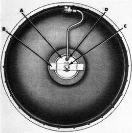
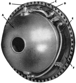
Figure 20-Forward Bulkhead of Welded Air Flask, showing (A) Small forward bulkhead installed in center; (B) Clamp; (C) Lock nut; (D) Nipple
bulkhead of the welded flask (Fig. 20) is installed and removed in the same way as the bulkhead for the forged flask, but it is held in place by means of a locating clamp, stud, and lock nut, shown in Fig. 21.
No lifting eye bolts are needed for manipulating the small bulkhead.
When inserting the small bulkhead, the two flat sides of the bulkhead pass through slots in the seat; then it is turned so that the flat sides are seated clear of the slots.
In both types of air flask, air is led into the air compartment, during charging, by way of the stop and charging valve, to be described later, through the main air-connection pipe, and the dry pipe. After charging, air is led from the air compartment through the dry pipe, the main air-connection pipe, and the stop and charging valve to the starting and reducing valve and the super-heating system. A central nut and nipple secure the forward end of the main air pipe to the
after bulkhead. Another central nut and nipple secure the after end of the main air-connection pipe to the water compartment bulkhead.
The dry pipe is provided to prevent water or oil from running into the main air-connection pipe when the torpedo is floating vertically at the end of an exercise or practice run. It is fitted and brazed into the nipple in the after bulkhead.
The main air-connection pipe is coiled to allow for relative expansion and contraction in the air and water compartments.
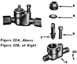
Blow Valve
The blow valve, shown in Figs. 22A and 22B, is located at the upper central part of the forward bulkhead, as shown in Fig. 20, and releases air from the air flask to the air-releasing mechanism of the exercise head. It is manipulated from the exterior of the air flask shell.
The free end of the pipe leading from the blow valve connects with a nipple in the pocket on the after bulkhead of the exercise head. (See Fig. 9.)
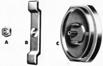
Figure 21-Small Forward Bulkhead, removed-(A) Lock nut; (B) Clamp; (C) Small forward bulkhead; note "flats" for passage through slots in seat.
Water Compartment
The water compartment is forged integrally with, and is located immediately abaft, the air compartment (see Figs. 18 and 19), and is closed at its forward end by the after bulkhead of the air compartment. At its after end, the water compartment is closed by the water-compartment bulkhead, which is held against a ground ring seat at its after end.
30
Figures 22A and 22B-The Blow Valve, which releases air from air flask to air-releasing mechanism of exercise head, assembled and disassembled-(A) Retainer; (B) Washer; (C) Valve; (D) Holding screw; (E) Valve body; (F) Set screw.
In addition to sealing the water compartment, the water compartment bulkhead supports the fuel flask by four brackets attached to its inner surface, as shown in Fig. 23. It also provides an avenue for the main air-connection pipe through a central opening, also shown in Fig. 23.
Air from the air checks is led through a
nipple in the reinforced portion of the water compartment bulkhead to a pipe leading to the top of the fuel flask; and the fuel is forced from the fuel flask to the fuel and water checks, by air pressure, through a pipe extending down into the bottom of the fuel flask, and through a nipple in the reinforced portion of the water-compartment bulkhead.
Air from the air checks to the water compartment is delivered through a nipple, which replaces one of the bulkhead holding screws, to a pipe leading to the top of the water compartment. Water from the water compartment to the fuel and water checks is forced by air pressure through a pipe extending down into the bottom of the water compartment, and through a nipple which also replaces one of the bulkhead holding screws. These connections are shown in Fig. 24.
An opening in the top of the water compartment provides the filling hole for the water (see "F" in Fig. 19), and also access to the filling plug for the fuel flask. When filling, the plug is removed from the filling hole in the top of the water compartment; then the plug is removed from the fuel
Figure 23-The Fuel Flask (at left), and the Water-Compartment Bulkhead. The right and center views show the inner and outer faces of the water-compartment bulkhead. (A) Nipple for air to fuel flask; (B) Bosses for mounting fuel flask on water compartment bulkhead brackets; (C) Nipple for fuel to fuel strainer and check valve; (D) Fuel-filling hole; (E) Fuel-flask brackets; (F) Nipple for pipe to fuel strainer and check valve, connects with "C"; (G) Nipple for pipe from air check valve, connects with "A"; (H) Blow-out plug and nipple; (I) Opening for main air pipe.
31
flask. The flask is filled, the plug replaced; then the water compartment is filled.
To protect against corrosion, the interior surfaces of the forged air flask are electroplated with cadmium. The interior surfaces of the welded air flask are coated with a baked phenolic resinoid coating.
Blow-Out Plug
To guard against destructive pressure, which might be built up in the water compartment by the absolute failure of the reducing valve, or to a rupture in the main air line passing through the water compartment, a blow-out plug (Fig. 25) is provided. The blow-out plug is located on the upper portion of the after face of the water-compartment bulkhead. (See "H" in Fig. 23.)
The arrangement of the blow-out plug is such that the plug will blow out at a pressure of about 1200 p.s.i. in the water compartment, thereby providing a seven eighths-inch clear opening for venting the pressure in the water compartment.
This opening in the water-compartment bulkhead is large enough to pass water at a
Figure 24-Water Compartment Bulkhead with Fuel Flask Assembled-(A) Fuel flask; (B) Fuel-filling plug; (C) Blow-out plug; (DI Air Inlet pipe; (E) Fuel outlet pipe; (F) Water compartment bulkhead
sufficient rate to prevent a rise of pressure in the water compartment in excess of 1500 p.s.i., even though the main air pipe should rupture.
Fuel Flask
The fuel flask (see Figs. 23 and 24) is constructed in the shape of a thick doughnut
in order to permit its installation in the limited space available in the water compartment. It is formed of brazing brass, and is tested to 50 p.s.i. internal pressure after complete assembly with fittings. The filling flange is located on top of the flask, so that it is directly under the water-filling flange, thereby giving access through the water-filling hole for removing and replacing the fuel-filling plug, and for filling the fuel flask.
The air-inlet connection is located in the same fitting body as the fuel-filling plug, and enters the top of the flask as shown in Fig. 24. The fuel outlet connection is located at the bottom of the flask, a perforated tube being provided to strain out large foreign particles. The air-inlet and the fuel-outlet nipples are connected by pipes to their respective nipples on the interior of the water compartment bulkhead, as shown in Fig. 24.
32
Midship Section
The midship section (see Figs. 18 and 19), which is a forged steel ring, is, as has been stated, an integral part of the air-flask section, being riveted and soldered to the after end of the air-flask in both the forged air flask and the welded air flask. In both cases it becomes a permanent part of the air-flask section shell. The after end of the midship section is machined to form a joint with the afterbody.
The midship section consists of a ring, closed at its forward end by the water compartment bulkhead (see Fig. 19), and closed at its after end by the turbine bulkhead of the afterbody.
As has been previously stated, the mid-ship section provides a cooling chamber for those parts of the operating mechanisms which convey hot gases, and which must be externally cooled in order that they will not be injured by the interior temperature. The nature of these parts, therefore, as with all other parts found in the midship section, does not require the exclusion of water from their exterior surfaces. Hence, the midship section has openings which admit sea water and permit it to circulate freely through the section and around the parts which require cooling.
Openings in the midship section also provide access for adjustment or manipulation of certain parts which are enclosed in the midship section. Among these parts are included those attached to the turbine bulkhead, which is the forward bulkhead of the afterbody, and which are known as the valve group and superheater. These will be described in the next chapter.
The shell of the midship section is marked at each opening, indicating the parts to which access may be gained, these parts being the following: (a) stop and charging valve; (b) air checks; (c) fuel and water strainers and checks; (d) air-vent pipe access opening for the vent fitting; (e) speed-setting mechanism; (f) main air connection; (g) air connection to air check valve body; (h) fuel and water connections to fuel and water check valve and strainer
body; (i) igniter; (j) air connection to igniter.
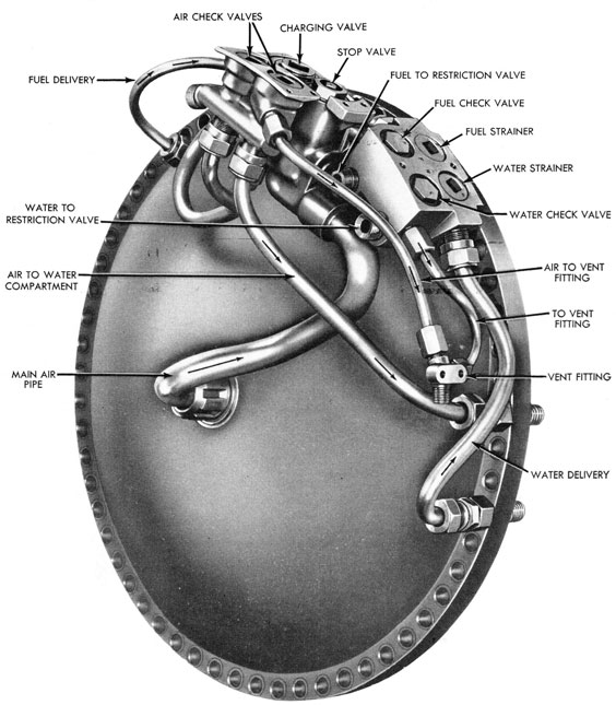
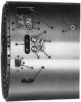
Major Fittings Attached to the Midship Section
The stop and charging valve body, the air check valve body, the fuel and water check valve and strainer body, the speed-setting bracket, and the vent fitting, are all attached to the shell of the midship section, being held in place by screws, so they can be readily removed. These parts, with connecting pipes, are shown in Figs. 26A and 26B.
Fig. 27 is a view of the midship section topside, showing the valves and fittings in place, attached to the shell.
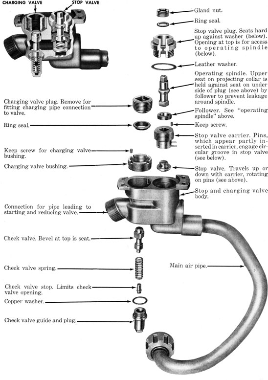
Stop and Charging Valves
The stop and charging valves are contained in one body, and are located at the top of the midship section, as shown in Fig. 19, and at (D) and (E) in Fig. 27. They are attached by screws to the top of the midship section shell, but connect with the main air pipe leading through the water compartment bulkhead.
The charging valve provides a means for charging the air flask. A check valve under the charging valve prevents leakage of air outboard when the charging line is removed. The stop valve is operated manually and isolates the air in the air flask after charging and until it is ready for use. With the stop valve closed, the afterbody may be removed and overhauled while the air flask remains fully charged.
A cut-away view of the stop and charging valve body is shown with the parts disassembled in Fig. 28. For charging the air flask, the plug is removed from the charging valve, preventing the escape of air from the air flask. The charging-pipe connection is screwed into the threaded hole from which the plug is removed.
The stop valve closes air-tight on its seat in the valve body. It has a plug which seats in the stop valve body against a washer. This plug has an opening which permits access to the valve-operating spindle for opening or closing the valve. Packing, retained
33
Figure 26A-Valves and Fillings Attached to the Midship Section
34
Figure 26B-Valves and Fittings Connected to Water-Compartment Bulkhead
35
by a gland nut, is provided. The operating spindle is held in place in the plug by a follower which allows freedom of revolution. A square shank at the lower end of the operating spindle fits into the stop valve carrier, in which the stop valve is fitted, by means of two small pins, in such a manner that it is free to rotate but travels with the carrier. Turning the operating spindle screws the carrier up or down, lifting or seating the stop valve.
In charging the air flask, the air passes through the charging valve and stop valve to the main air pipe which leads to the air flask. When the air flask is fully charged, the supply valve is shut off, the stop valve is closed, the charging line is bled and disconnected, and the charging valve plug is replaced.
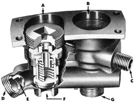
Air Check Valves
The air check valves are identical in assembly, and are contained in one body (see Fig. 29, which shows a cut-away view as well as the parts disassembled.) They are interposed between the reducing valve and the fuel and water compartments (see Fig. 26B). Their purpose is to close these two compartments against each other, and both compartments against the reducing valve, opening only when the torpedo is in normal operation. The checks also vent pressure caused by air leaks into the water compartment. Were it not for this venting feature, the pressure created by leaks would cause the water delivery check valve to unseat and force water into the combustion flask.
The body of the air check valves is secured by screws to the midship section shell (see "B" and "C" in Fig. 27) aft of the stop and charging valves. In the inlet nipple (see "E" in Fig. 29) is a restriction which checks any sudden flow of air and permits the pressure to equalize on both sides of the fuel flask at the instant of opening, thereby preventing a possible rupture of the fuel flask.
The spaces above the check valve plugs are closed by screw plugs, and are interconnected by an air vent passage, the entire space being vented into the afterbody
by a pipe passing to the vent fitting attached to the midship section shell.
Venting of the air check valves is necessary to prevent pressure accumulation above the valve from cushioning the valve or preventing its opening.
Reduced air pressure, upon entering the inlet nipple, will immediately fill the passage around the air check valves and, because the areas of the beveled surfaces of the valves above their seats are larger than the opposing area on the flat seats, will open the valves against the pressure of their springs and hold the valves open until the spring pressure again exceeds the forces tending to open the valves, at which time the valves will close. The air pressure
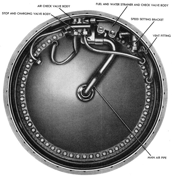
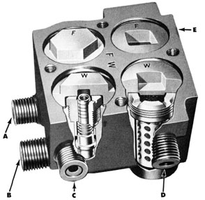
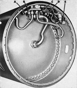
Figure 27-Midship Section, Top View. (A) Access hole, permits connection of air pipe to air check valves and main air connection to air flask after assembly of after-body to air flask; (B) Fuel air check valve; (C) Water air check valve; (D) Charging valve; (E) Stop valve; (F) Water-filling plug, when removed, gives access to fuel filling plug; (G) Access hole to fuel and
water connections; (H) Fuel check valve; (I) Fuel strainer; (J) Water check valve; (K) Water strainer; (L) Speed-setting mechanism; (M) Access hole to vent fitting.
36
Figure 28-Stop and Charging Valves, cut-away and disassembled views.
37
required to unseat the valves when acting against the beveled area above the valve seat is 10 to 12 p.s.i.
The air check valves may also be considered as relief valves, in that any pressure accumulated in the fuel or water compartment in excess of five to six p.s.i. will act against the areas under the air check valve seats. This unseats the valves and relieves such pressure through the restriction valve and combustion flask.
The air is conveyed from the air check valves through pipes connecting through the water compartment bulkhead to the top of the fuel and water compartments.
Vent Fitting
The vent fitting (see Fig. 26B) is attached by screws to the midship section shell, as shown in Fig. 27, and is located on the starboard side. It receives any leakage of air from the outboard seats of the fuel and water check valves, and any leakage of air from the outboard side of the air check valves, venting this leakage into a pipe connecting with the afterbody.
Fuel and Water Strainers and Check Valves
The fuel and water strainers and check valves (Fig. 30) form a group of four units
Figure 29-The Air Check Valves, cut-away and disassembled. Note: Valve assemblies on fuel (A) and water (B) sides of check valves are identical. Note passage above
valve plugs from fuel to water side; accumulated pressure due to air leakage vents through this passage to outlet (C) which leads to vent fitting. Connection (D) for air from reducing valve has restriction at (E) which checks any sudden flow of air which might rupture fuel flask. (F) is outlet for air to fuel flask; (G) is outlet or air to water compartment.
38
housed in one body casting. They are interposed between the fuel and water compartments and the restriction valve, the body being attached by screws to the mid-ship section shell, as shown at "H", "I", "J", and "K" in Fig. 27. (Also see Fig. 26B.) They perform two important functions: first, the strainers pick up any foreign matter which might be in the fuel or water before they reach the combustion flask, thereby preventing the possibility of clogging the sprays. Second, the check valves automatically seal the fuel and water compartments against leakage of fuel and water through the restriction valve to the sprays and into the combustion flask until they are opened by reduced air pressure upon launching of the torpedo. The valves are of the poppet type and are double acting, preventing leakage outboard when open, as well as to the sprays when closed.
The fuel and water inlet nipples are arranged so that the liquid enters through the
Figure 30-Fuel and Water Strainers and Check Valves, parts disassembled at left, cut-away view below. Fuel passes to combustion flask through "A"; water passes to combustion flask through "B"; "C" is lead to vent fitting; "D" water from water compartment; "E" fuel from fuel flask (nipple not visible).
39
top of the strainers and, passing through, emerges at the bottom under the check valves, thence through these valves to their outlet nipples directly above the valve seats.
Springs (Fig. 30) normally keep the check valves on their seats, 15 to 20 p.s.i. pressure being required to unseat either valve. The spaces above the valve guides are closed by screw plugs seated against
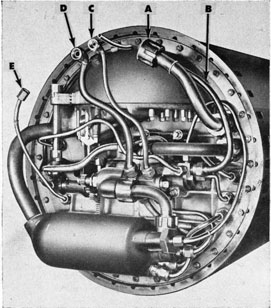
Figure 31-Connections from the air flask section to the afterbody-(A) Connection from stop and charging valve to preheater; (B) From reducing valve to air check
washers, and are interconnected by air-venting passages to the vent pipe, thence to the vent fitting.
From the check valves, the fuel and water pass through pipes to the restriction valve and thence to the sprays in the combustion flask.
Connections from Air Flask
to Afterbody
The connections from the air flask to the afterbody are shown in Fig. 31.
following chapter will describe these connections in their relation to the operating mechanisms of the torpedo.
Preheater
The preheater, which is a coil of copper tubing in the path of the exhaust gases above the turbines, serves to preheat the
valves; from water compartment to water spray in combustion flask; (D) from fuel flask to fuel spray in combustion flask; (E) from vent fitting to afterbody
high-pressure air passing from the stop and charging valve to the starting and reducing valve. Located, as it is, in the exhaust chamber, the preheater transfers heat from the exhaust gases to the high-pressure air passing through the preheater.
This preheating, while conserving some of the heat otherwise lost in the exhaust gases, has its major value in promoting improved reducing-valve action, since the reducing valve will operate better with warm air.


 1 Page _____ Page 1
 1 Page ____ Page 1