3. Move pendulum hard up against stop farthest from pot (forward stop). There should be 0.494-inch to 0.500-inch clearance between the after section of the pendulum and the stop on the depth mechanism casing. (Use a piece of stock ground to 0.494-inch for this test.)
Note: If pendulum touches the gyro pot, the slots that hold the pins of the pendulum after section are probably spread. These slots may be closed about the pins by light taps with a small hammer. Should the after section still not clear the pot, the after section should be ground to clear.
4. Move pendulum hard up against the forward and after stops. There should be clearance between the sides of the knife edges and the knife-edge bearings in both positions.
5. Replace transportation screw and check pendulum stop clearances. They should be 0.247-inch to 0.250-inch. Remove transportation screw. (49)
B. Disassemble Depth Mechanism
1. Remove air chamber:
(a) Remove plug and washer from air chamber. (11)
(b) Remove holding nuts. (48)
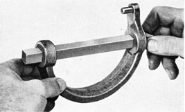
(c) Install lifting tool and remove air chamber. (409)
2. Remove diaphragm and diaphragm ring:
(a) Remove cotter pin from diaphragm nut. (72)
(b) Hold diaphragm plate with Tool No. 461 and unscrew diaphragm nut. (461, 410)
(c) Remove diaphragm plate. (Pry off with screw driver.)
(d) Remove diaphragm.
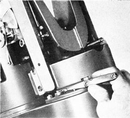
(e) Swing pendulum full throw in both
directions and measure clearance between free end of diaphragm lever and its stop for both positions of pendulum (Fig. 229). This clearance should be 0.015-inch to 0.020-inch. If clearance in either position is not correct, make necessary adjustment with linkage-adjusting screw on pendulum. (WE2A)
Figure 229
(f) Remove holding nuts, diaphragm ring, and gasket. (48)
3. Remove pendulum lever and diaphragm-lever shaft:
(a) Remove cotter pin and pin for pendulum link to pendulum lever. (72)
(b) Remove keep screw for diaphragm-lever shaft. (41)
(c) Remove pendulum lever and diaphragm-lever shaft assembled.
Note: Insert a soft brass rod in back of pendulum lever close to its hub, and tap out the shaft. Great care must be exercised not to bend this shaft when removing it.
4. Remove depth-spring assembly:
(a) Turn depth-spring adjusting spindle clockwise until threads on adjusting
209
screw disengage threads in upper depth-spring socket. (180)
(b) Remove depth spring with sockets and diaphragm-lever assembled.
*(c) Remove cotter pin, washer, pin, and diaphragm-lever from lower depth-spring socket. (72)
5. Remove pendulum:
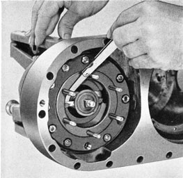
(a) Remove two screws and after section of pendulum. (40)
(b) Remove depth-spring adjusting spindle:
(1) Remove cotter pin from bottom of spindle. (72)
(2) Hold spindle with tool in spring-adjusting head and unscrew nut on the lower end. (180, 155)
(3) Lift spindle out of its bearing from the top, removing gear on the bottom end.
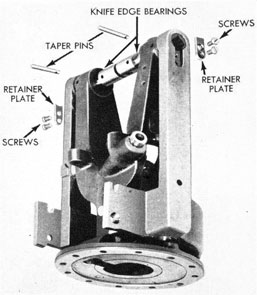
(c) Remove holding screws from knife-edge retainer plates and remove retainer plates. (41)
Note: Retainer plates should be marked before removal and replaced on the side from which removed.
(d) Remove cotter pins and taper pins for knife edges. Start taper pins with a small brass hammer.
(e) Remove knife edges by tapping from outer ends toward center.
(f) Remove forward section of pendulum.
6. Remove adjusting screw and idler gear:
(a) Remove depth-spring adjusting screw (with ring seal) and idler gear.
*(b) Remove ring seal from adjusting screw.
*7. Remove pendulum-adjusting linkage:
(a) Remove cotter pin and washer from pivot for linkage-adjusting arm. (72)
(b) Remove linkage-adjusting a r m with pendulum link.
(c) Remove pin in nut for linkage-adjusting screw. (166)
(d) Remove nut from linkage-adjusting screw.
(e) Back out clamp screw for linkage-adjusting screw. (41)
(f) Remove linkage-adjusting screw.
(41)
8. Remove depth-mechanism casing:
(a) Remove ten holding nuts. (48)
(b) Remove depth-mechanism casing and gasket from base.
The above completes the disassembly of the depth mechanism.
Figure 230
OVERHAUL, ASSEMBLY,
AND TEST
C. Depth Mechanism
1. Thoroughly clean and inspect parts, paying particular attention to seats, bearing surfaces, gaskets, threads, etc.
2. Check alignment of arms on depth-mechanism casing:
(a) Install and temporarily secure knife edges in arms of casing.
(b) Extend a line through the center of depth-mechanism casing and stud holes directly under knife edges. If not already done, scribe marks on edge of casing on this line.
210
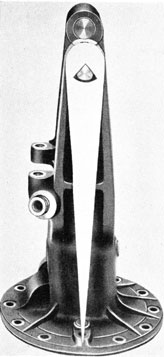
(c) Place depth-mechanism casing on a leveled surface plate.
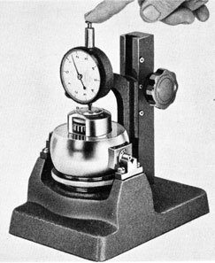
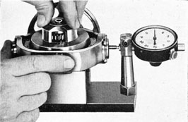
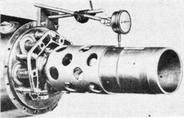
(d) Place pointer gage on each knife edge and note if pointer comes to rest on scribe marks (Fig. 230); if not, arms are out of alignment and must be sprung into proper alignment. (WE186)
Figure 231
(e) When satisfied that casing arms are in alignment, remove casing from surface plate, and remove pointer gage and knife edges.
3. Replace depth-mechanism casing:
(a) Clean and inspect mechanism base and depth-mechanism casing, including seats and bearing surfaces, for burrs. Inspect studs for tightness; renew where necessary. Inspect all screw holes for burrs or damaged threads. If necessary, remove burrs with a scraper, and clear tapped holes with a tap. Run a finger die over studs with damaged threads. (490)
(b) Place a new gasket over studs on seat.
(c) Install casing on mechanism base and secure with ten holding nuts, tightening up evenly. (48)
4. Check fit of diaphragm-lever shaft in its bearing in depth-mechanism casing:
Note: Diaphragm-lever shaft must be capable of rotating freely in its bearing.
(a) Remove ring seal from diaphragm-lever shaft.
(b) Replace diaphragm-lever shaft and pendulum lever in bearing.
(c) Replace gasket and diaphragm ring. Secure with nuts. (48)
(d) Replace air chamber and secure with nuts. (48)
(e) Stand mechanism on its forward end; move pendulum lever up as far as it will go and note if it will drop of its own weight. If not, remove air chamber, diaphragm ring, and casing, and inspect seat of casing, base, and diaphragm ring for burrs which may cause the warping of the diaphragm-lever shaft bearing with nuts set up tight. Re-assemble and repeat test. (48)
(f) After satisfactory test has been made, remove air chamber, diaphragm ring, gasket, diaphragm-lever shaft, and pendulum lever.(48)
*5 Replace pendulum-adjusting linkage:
(a) Replace linkage-adjusting screw on pendulum. (41)
(b) Tighten clamp screw for linkage-adjusting screw. (41)
(c) Replace nut for linkage-adjusting screw and secure with pin. (166)
Figure 232
211
(d) Replace linkage-adjusting arm with pendulum link.
(e) Replace washer and cotter pin on pivot for linkage-adjusting arm. (72)
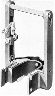
6. Replace forward section of pendulum:
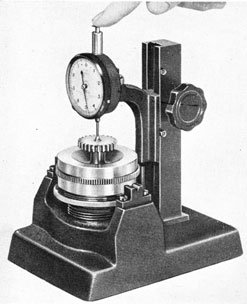
(a) Check pendulum arms for alignment (Fig. 231). (WE184)
(b) Place pendulum around depth-mechanism casing, lift arms into alignment with holes in casing arms, and install knife-edge bearings with holes for taper pins in line.
Figure 233
Note: It is important that knife edges are sharp and free of burrs.
(c) Check clearance between guides and mating rollers with mechanism inclined 30 degrees both ways from the vertical. In these positions, the guides should not contact their mating rollers (Fig. 232). (WE2A)
Note: If the above clearance is not obtained, it will be necessary to remove pendulum and stone guides.
(d) Replace taper pins for knife edges and secure with cotter pins. (72)
(e) Straighten if necessary; replace knife-edge bearing retainer plates and secure with screws (Fig. 233). (41)
Figure 234
(f) Check clearance between retainer plates and knife edges (Fig. 234). This clearance should be not less than 0.005-inch nor more than 0.007-inch. If clearance is less than 0.005-inch, remove retainer plates and stone upper surfaces.
(WE2A)
(g) With mechanism level, measure clearance between pendulum arm and "Y" arms of casing (Fig. 235). This clearance should be at least 0.010-inch. If sufficient clearance is not obtained, binding
Figure 235
212
may occur. Check "Y" arms, pendulum arms, and small clearance lugs on knife-edge bearings. (WE2A)
7. Replace after section of pendulum and secure with two screws. (40)
8. Check pendulum clearances. (See steps A-2, 3, 4, and 5).
9. Check swings of pendulum:
(a) Level mechanism.
(b) Place a one-pound weight in forward portion of pendulum (to balance pendulum).
(c) Hold pendulum all the way in the forward position. Release pendulum and note number of swings it makes. The pendulum should make at least 16 swings before coming to rest.
Note: If pendulum does not make the required number of swings, check arms of casing for alignment (see step D-2),
Figure 236
and check knife edges and knife edge bushings for burrs.
(d) Remove one-pound weight from pendulum.
10. Replace depth-spring ad j u s t i n g spindle and gears:
(a) In the case of torpedoes which have a synthetic-rubber ring seal on the depth-spring adjusting screw, check clearance between bearing surface diameter on adjusting screw and hole in depth-mechanism casing. This clearance should be at least 0.001-inch.
*(b) Roll ring seal into groove on depth-spring adjusting screw.
Note: In order to prevent damage to seal when rolling it over threads on adjusting screw, wrap a piece of paper around threaded portion of screw and roll ring seal over paper into groove.
(c) Replace adjusting screw and idler gear.
(d) Replace adjusting spindle and gear; and secure gear to bottom of spindle with nut and cotter pin. (180, 155, 72)
11. Replace depth spring, diaphragm lever, and socket assembly:
*(a) Inspect diaphragm lever for trueness, using inspection plate (Fig. 236). (WE175)
Figure 237
*(b) Replace diaphragm lever in slot in lower spring socket; and secure with pin, washer, and cotter pin. (72)
(c) Replace depth-spring assembly, noting that spring guides line up with slots in casing; engage upper depth-spring socket with adjusting screw and turn adjusting spindle counter-clockwise until square hole in diaphragm level lines up with bearing hole in casing for diaphragm-lever shaft. (180)
12. Replace pendulum (long) lever and diaphragm-lever shaft:
*(a) Remove pendulum lever from diaphragm-lever shaft and check for trueness on inspection plate (Fig. 237).
Figure 238
Replace lever on shaft and secure with taper pin. (166, WE175)
(b) Roll new ring seal over end of shaft into groove.
(c) Replace pendulum lever and
213
diaphragm-lever shaft, assembled, in bearing, guiding shaft through hole in diaphragm-lever; secure shaft with keep screw. (41)
13. Connect linkage of pendulum to upper end of pendulum lever:
(a) Replace transportation pin. (49)
(b) With pendulum-linkage adjusting screw midway between its stops, turn depth-spring adjusting spindle until the hole in the pendulum link lines up with the hole in the pendulum lever. (180)
(c) Secure pendulum lever to link with pin and cotter pin. (72)
Figure 239
14. Check swings of pendulum. (See step 9, above.) The pendulum should make at least nine swings before coming to rest.
15. Replace diaphragm ring:
(a) Replace gasket for diaphragm ring over studs in mechanism base.
(b) Replace diaphragm ring and secure with ten nuts (Fig. 238). (48)
16. Check diaphragm lever clearances:
(a) Lay mechanism base on right side.
(b) Hold pendulum all the way in its after position and measure clearance between diaphragm lever and bottom of depth-mechanism casing. This clearance should be 0.015-inch to 0.020-inch.
(WE2A)
(c) Hold pendulum all the way in its forward position and measure clearance between diaphragm lever and ring. This clearance should also be 0.015-inch to 0.020-inch. (Fig. 239) (WE2A)
Note: If clearance in either position is not at least 0.015-inch, loosen clamp screw and turn pendulum-linkage adjusting screw to equalize diaphragm-lever clearances. If the clearances are not at least 0.015-inch, even though equalized, it will be necessary to remove stock from both sides of the diaphragm lever.
17. Replace diaphragm:
(a) Place a new diaphragm on diaphragm ring, with bulged side facing out.
(a) Replace air chamber over diaphragm and secure with six nuts. (48)
(b) Replace washer and access plug. (11)
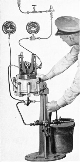
19. Measure torque required to turn depth-spring adjusting spindle:
(a) Place mechanism right-side-up on base.
(b) Insert Tool No. 180 (modified by an extension on the handle to give a one-foot moment arm) into socket head on depth-spring adjusting spindle. (180)
(c) Place tip of push balance on end of modified Tool No. 180, and note force required to start spindle turning. The push-balance reading should not exceed 2 1/2 pounds. (180, 98)
Note: If push-balance reading exceeds 2 1/2 pounds, locate cause and remedy.
(d) Remove modified Tool No. 180 from socket head.
20. Install transportation pin. (49)
The above completes the overhaul and assembly of the depth mechanism, except for the assembly of the bracket for pallet driving gear and the assembly of the tension rod and valve-lever assembly. These units must be assembled after the assembly of some of the gyro mechanism parts. (See steps E-14 and E-29.) Step F gives the test for the assembled depth mechanism.
214
D. Test Assembled Depth Mechanism
1. Ascertain that transportation screw is installed in mechanism. Install mechanism and gasket in Depth Mechanism Test Stand and secure with screws and expansion plugs.
(456)
2. Install pressure-chamber cover with proper side out, so that the access holes will align properly with the atmospheric-chamber plug and the transportation screw. Secure cover in place. (402)
3. Rotate pressure chamber to bring depth mechanism right-side-up.
4. Install depth engine on mechanism and connect valve connecting rod to the depth-linkage system. (49, 205A-246)
Note: The depth engine must be in proper working order. See step E.
5. Connect air line (450 p.s.i.) to the depth engine and turn on air. (141A)
6. Check alignment of scribe mark on depth-engine valve connecting rod with scribe mark on valve stop. If the marks do not line up, loosen clamp screw, turn valve connecting rod to obtain alignment, and tighten clamp screw. (205A-246)
Note: After the valve connecting rod has been turned, make certain that hole in knurled portion of connecting rod is horizontal. When this hole is horizontal, the small pivot pin, which secures the connecting rod to the valve, will be horizontal. If the pivot pin is not horizontal, the connecting rod will not have a proper pivoting movement with respect to the valve; also, if the pivot pin becomes loose, it may drop down and prevent proper valve action.
7. Turn off air.
8. Remove two access plugs from pressure-chamber cover. (410)
9. Remove transportation screw. (49)
10. The scribe marks on the depth-engine valve connecting rod and the valve stop should not move out of alignment when the transportation screw is removed. If a movement of the valve connecting rod is noticed, the test stand should be checked to see if it is out of level.
11. Install replacement screw. (49)
12. Remove atmospheric-chamber plug and install screw hook. (11)
Figure 240
13. Place a 10-pound weight on hook. (411A)
14. Turn on air to depth engine.
15. Rotate depth-spring adjusting spindle until depth-engine scribe marks are again in alignment. Move pendulum back and forth several times and note that scribe marks are in line when pendulum comes to rest (Fig. 240). (180)
16. Remove weight and screw hook.
17. Replace atmospheric-chamber plug and washer. (11)
18. Replace the two access plugs and washers in the pressure-chamber cover. (410)
215
Figure 241
19. Connect pipe from "T" block to nipple in pressure-chamber cover. (229)
20. Connect pipe from "T" block to nipple on depth-mechanism casing. (229, 144)
21. Turn two-way valve so as to deliver water to pressure chamber and depth-mechanism casing. (436)
22. Pump until water comes out of gage nipple in pressure chamber. Connect "seawater" gage pipe to this nipple. (141A)
23. Pump slowly, noting sea-water gage and depth-engine valve. Read gage: (1) When depth-engine valve begins to move ("Breakaway"), (2) when scribe marks
come into alignment ("center"), and (3) when valve is hard up against the valve stop ("Hard Up"). These readings should be:
Hydrostatic Pressure (in Feet of Sea Water) at Various Positions of Depth Engine
Valve
Breakaway
Center
Hard Up
3 to 4
9 to 10
17 to 20
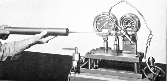
24. Continue pumping until gage shows 25 feet of sea pressure (Fig. 241).
25. Look for leaks in depth-mechanism casing, around diaphragm-lever shaft, and around depth-spring adjusting screw.
26. Turn two-way valve so as to drain the pressure chamber slowly. Read the gage: (1) when the depth-engine valve begins to move ("Breakaway"), (2) when scribe marks come into alignment ("Center"), and (3) when valve is hard up against the valve stop ("Hard Up").
The gage readings should not lag those found in step 23 by more than one foot of pressure at "Center" and two feet of pressure at "Full Throw" positions. (436)
27. Repeat steps 23 through 26 three times. The gage readings should check; and the operation of the depth-engine valve should be smooth and continuous, giving no indication of jerky or sticky operation. Slight leaks, which may not be apparent during the single test, are sometimes indicated on succeeding tests. This completes the test.
28. Turn off air to depth engine.
29. Turn two-way valve to drain water from pressure chamber to bucket. (436)
30. Remove an access plug to drain remainder of water from pressure chamber. (410)
31. Disconnect pipe from pressure-chamber cover to "T" block. (229)
32. Disconnect pipe from depth-mechanism casing to "T" block. (144)
33. Rotate depth-spring adjusting spindle to relieve all tension on depth spring. (180)
34. Disconnect gage lead from pressure chamber. (141A)
216
35. Disconnect air pipe from depth engine and remove depth engine.
(141A, 205A-246, 49)
36. Rotate pressure chamber to bring pressure-chamber cover on top.
37. Remove pressure-chamber cover. (402)
38. Remove mechanism from pressure chamber. (456)
E. Depth Engine
1. Test prior to disassembly:
(a) Mount depth-engine on Leakage Test Stand and connect to test lead. (49, 141A)
(b) Check centering of piston in cylinder as follows:
(1) Turn on air to 450 p.s.i. on low-pressure gage.
(2) Move valve against stop in one direction.
(3) Turn air off.
(4) Push piston by hand in same direction as valve was moved. A movement of 1/64 inch should be noted
Figure 242
before end of piston touches cylinder head. (WE8)
(5) Turn on air to 450 p.s.i. on low-pressure gage.
(6) Move valve against stop in reverse direction.
(7) Turn air off.
(8) Push piston by hand in same
direction as valve was moved. A movement of 1/64 inch should be noted before end of piston touches cylinder head. If the 1/64 inch movement is not noted at each end, adjust the valve stop toward end where most clearance is noted, and try against above until
Figure 243
equal clearance is obtained between piston and cylinder on both ends.
(WE8)
(c) Turn on air until high-pressure gage reads 800 p.s.i.
(d) Move valve and take low-pressure gage readings when piston is at each end of the cylinder. These readings should lie between 400 and 650 p.s.i. and should not differ from one another by more than 20 p.s.i.
(e) Rotate piston in 90-degree increments, repeating step (d) of test at each of the four rotational positions of the piston.
Note: When rotating the piston, move it back and forth with the valve, so as not to score the cylinder.
(f) With air on engine, test sensitivity of valve, using a feather gage to move it (Fig. 242). The valve and piston should move in either direction with a force of 1/2-ounce or less. (222)
(g) Test cylinder head, inlet nipple, and piston rod packing glands for leaks, using oil (C).
Note: The piston should always be at the opposite end from that being tested for leaks, so that the end being tested will be under air pressure.
217
(h) Turn off air.
(i) Test tightness of packing by using a push balance to move the piston (Fig. 243). This should not read over 27 pounds. (98)
(j) Disconnect test lead from engine, and remove engine from test stand.
(141A, 49)
The above test is made to facilitate inspection of condition during overhaul. 2. Disassemble engine:
(a) Clamp holding block (SG 2537) for depth-engine in vise; mount engine on
block and secure. (49)
(b) Remove valve stop. (41.)
(c) Remove valve stop plug and valve from piston. (159)
(d) Unscrew packing glands about a turn. (169)
(e) Remove piston fork by loosening clamp screw and wedging screw driver in clamping slot until threads on fork turn freely. Scribe position before removal and count turns. (49, 41)
(f) Remove cylinder head and washer. (377)
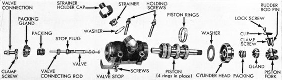
Figure 244
(g) Push piston out of cylinder and place where lapped surfaces will be protected against marring.
(h) Remove two packing glands and packing. (169, 482)
(i) Remove strainer-holder cap, washer, and strainer. (402)
(j) Immerse all parts, except packing, in grease solvent and blow dry with air.
(k) Immerse new packing in oil (D) until ready for use.
Figure 245
3. Inspect parts for wear and defects:
(a) Note if any scratches or small scores appear on inside of depth-engine cylinder.
(b) Examine piston rods for burrs or scratches. Examine piston rings for wear; piston rings should show even wear throughout their convex surfaces. There should be no tendency for rings to bind or stick in grooves; butt ends should be free, with no noticeable clearance.
(c) Observe butt clearance by inserting piston, with rings, in cylinder, noticing rings as they enter cylinder. If butt clearance is noticeable by eye, the rings are worn too much and should be replaced. (230)
(d) Examine valve hole for burrs or scratches, particularly around annular air grooves for valve.
(e) Examine valve for scratches and burrs.
(f) Check valve for alignment, using straight edge or surface plate.
(g) Examine strainer and strainer holder.
Figure 246
218
*4. Lap out any scratches or burrs found in depth-engine cylinder, using lapping compound only if necessary. Lap to final size, using oil (C) (Fig. 244). (WE140, 41)
*5. Lap out any scratches or burrs found on piston rods, using lapping compound sparingly, if necessary (Fig. 245).
(WE139, 41)
*6. Fit new piston rings:
Note: In the case of depth engines which have hammered piston rings (hammered piston may be identified by the fact that their butt ends are "square" instead of diagonal) the piston rings should not be lapped; they must be replaced by rings which have diagonal butt ends. The procedure for fitting new rings in all depth engines is given below.
(a) Remove worn rings from piston.
(b) Adjust male lap, WE140, to fit cylinder snugly. (WE140, 41)
(c) Measure diameter of WE140 after adjusting to fit cylinder. (WE6, WE140)
(d) Adjust WE140 so that it is 0.002-inch larger in diameter than bore of cylinder. (WE140, WE6, 41)
Figure 247
(e) Insert WE140 into female lap, WE141, and adjust female lap, WE141 to fit WE140 snugly (Fig. 246).
(WE140, WE141, 41)
(f) Select new rings and see that they are free from burrs. If possible, select rings that will fit WE141 without dressing down the butt ends. (WE141)
Note: If necessary to remove metal on butt ends to fit rings into lap, WE141, use a small flat file, and finish by stoning. Remove burrs after filing and stoning.
(g) Measure width of rings. (WE5)
(h) Slip rings, one at a time, over lap holder, WE142, and rub down to a width
Figure 248
of 0.096-inch against a piece of No. 0 emery cloth laid on a smooth and level surface. (WE142, WE5)
(i) Finish lapping rings against smooth side of combination oil stone, (Fig. 247) trying rings in grooves on piston until a snug fit without binding is obtained. (WE142)
(j) After lapping, wash piston and rings thoroughly with a suitable grease solvent and blow dry with air.
(k) Place all rings in female lap.
(WE141)
(1) Remove clamp bolt, washer, and sleeve on lap plug holder, WE insert this tool through piston rings in WE141; slip washer over end of WE138 and secure with clamp bolt.
(WE141, WE138, 144)
(m) Remove WE138, with rings, and examine all rings to see that butt ends are closed together.
(n) Lap rings in WE141, using the medium-fine grade of compound (Fig. 248). Gradually tighten up on lap until rings are 0.001-inch larger in diameter than bore of cylinder.
(WE141, WE138, WE6, 41)
(o) Change to fine grade of lapping compound and finish lapping rings with oil (C) until they reach the inside diameter of the cylinder.
(WE141, WE138, WE6, 41)
219
Note: Remove lap-plug holder, WE138, from WE141 occasionally during lapping and note if entire outside surface of each ring contacts lap. If there is any doubt about a ring not lapping out, it is best to replace such ring before proceeding any further, as the whole set must be finished lapped together.
Figure 249
(p) After rings have been lapped to size of cylinder, wash clean with oil (C) and try WE138, with rings, in cylinder. If rings fit too snugly, do not attempt to force them into cylinder, but replace in WE141 and continue to lap and try again until fit is obtained.
(WE138, WE141, 230)
(q) Remove rings from WE138; wash thoroughly with grease solvent and assemble them on piston. (WE138, 144)
*7. Lap valve hole in piston:
(a) Adjust male lap, WE147, to size of valve hole in piston. (WE147)
Note: In making this adjustment, great care must be taken not to mar end of lap. Using a piece of copper stock having a 3/16-inch hole, line up end of lap in this hole and tap lap handle lightly with
a small bronze hammer, trying lap in hole for valve until final adjustment is obtained.
(b) If any burrs or scratches are found in valve hole, use a small quantity of fine lapping compound, applying evenly over surface of lap. (WE147)
Note: In lapping, move lap with a turning and reciprocating motion over total
Figure 250
length of hole to obtain a uniform diameter throughout its length. Do not lap more than necessary to remove burrs and scratches.
(c) Carefully wash lapping material off lap and out of hole with a grease solvent, and blow out carefully with low-pressure air.
(d) Lap hole with oil (C) until it shows a well polished surface (Fig. 249).
(WE147)
(e) Wash hole and lap with grease solvent and blow dry with air.
*8. Fit new valve:
(a) Measure diameter of lap, WE147, after finish lapping hole in piston, as done in step 7- (d), above. Pick out a spare valve about 0.0025-inch larger than this diameter. (WE147, WE5)
Figure 251
220
(b) Disassemble valve and connecting rod by placing valve in resting block, with pin lined up with hole in block, and drive out pin with 1/16-inch drift.
Note: Block and drift are not furnished; they should be made up by activity performing this step.
(c) Apply lapping compound sparingly on surfaces to be lapped, and insert valve in female lap WE148. Regulate adjusting screws in lap for proper friction and proceed to lap, moving valve in lap with a turning a n d reciprocating motion throughout its length (Fig. 250).
(WE148, 41)
(d) Remove, examine, and measure diameter occasionally during lapping. Change to finest grade of lapping compound when valve measures 0.0005-inch large, and lap down to size.
(WE148, WE5, 41)
(e) Wash compound from lap and valve with grease solvent, and blow dry with air.
(f) Finish lapping to a polish with oil
(C). (WE148)
Note: The valve must be as nearly perfect a fit in piston as is possible to get without any appreciable friction when finished. See step K-1-(f) for test of sensitiveness of valve.
(g) After lapping, wash lap and valve with grease solvent and blow off with low-pressure air.
(h) Assemble valve and connecting rod and secure with pin, using resting block and drift.
9. Assemble engine (Fig. 251):
(a) Oil (C) all parts, except packing.
(b) Clamp holding block (SG 2537) for depth engine in vise; mount engine on block and secure. (49)
(c) Place butt ends of piston rings 180 degrees apart on piston and insert piston, with rings, into cylinder, being careful not to mar parts. (230)
(d) Replace and tighten cylinder head and copper washer. Renew washer if necessary. (377)
(e) Renew packing, being careful not
to mar piston rods by using any sharp tools for pushing packing into place.
Note: An 11-inch length of packing is used for each gland. New packing should be immersed in oil (D) until ready for use.
(f) Install packing glands and set up hand-tight.
(g) Screw piston fork on piston to scribe mark, using same number of turns as on disassembly. Replace and tighten clamp screw. (49)
(h) Tighten up on packing glands gradually, turning and pushing piston back and forth by hand to work packing in around rods. (169)
(i) Insert depth-engine valve in piston and tighten valve stop plug. (159)
(j) Center piston in cylinder, using
steel scale. (WE8)
(k) Center valve in piston. (WE8)
Note: Hole in knurled portion of valve connecting rod must be horizontal.
(1) Replace valve stop and adjust it so that scribe mark on stop lines up with scribe mark on valve connecting rod. Clamp adjustment with screw. (41)
(m) Make certain that strainer is clean, and replace it in nipple on cylinder.
(n) Replace washer and strainer holder cap. Tighten cap. (402)
10. Center valve and piston with air on engine. [See steps K-1-(a) and (b).]
11. Test valve for sensitiveness. [See
step K-1- (f).]
12. Test assembled depth engine. (See step K-1.)
F. Test and Disassemble Gyro Mechanism
1. Test gyro spinning and unlocking mechanism:
Note: Before removing the spinning and unlocking mechanism, it should be given a Lest to determine whether or not it will be necessary to overhaul it. If mechanism does not pass the test outlined below, it must be disassembled, overhauled, assembled, and tested before it is used again. (See step I.)
(a) Remove gyro clamp plate cover
and gasket. (13-1.4)
(b) Lock and unlock mechanism
221
several times. When mechanism is properly locked, hand trip lever will be flush against wall of gyro pot. If lever is not flush, unlock mechanism, turn spinning turbine, lock mechanism, and again note position of hand trip lever.
When mechanism unlocks, make certain it does so with a snap. Slow or sticky operation must be corrected by a thorough cleaning or overhaul.
(205A-246)
(c) Lock mechanism; draw a pencil mark on spinning turbine for reference; and count number of turns required to unlock (should be 58 to 62 turns).
(205A-246)
(d) If Mechanism does not unlock with 58 to 62 turns, make necessary adjustment with duration-adjusting element.
(41)
(e) Lock mechanism (205A-246)
(f) Connect high-pressure air line (2800 p.s.i.) to gyro spin nipple; turn on air and check for leaks around nipple joint and nozzle holes, using oil (C).
(229)
(g) Turn off air; remove air line; and unlock mechanism. (229)
2. Remove six holding screws and spinning mechanism from gyro pot. (40)
3. Remove gyro reducing valve and pipes:
(a) Disconnect air pipe from gyro reducing valve to elbow in top plate. (24)
(b) Remove two holding screws and remove gyro reducing-valve assembly.
(205A-246)
4. Disassemble parts on top plate:
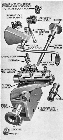
(a) Remove two holding screws for bearing cap; remove bearing cap, valve rock shaft assembly, spring buttons, and springs. (41)
*(b) Remove clamp screws and washer for adjusting head, and remove adjusting head and valve connection-arm assembly from valve rock shaft. (.11)
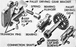
(c) Remove two keep screws and trunnion pins for pallet driving-gear bearing. (41, 91)
(d) Remove pallet driving gear with bearing and bearing cap; and remove
connection shaft, bearing plunger, and spring.
(e) Remove four bearing-cap screws, bearing cap, and pallet driving gear (41)
(f) Remove six holding screws, driving spindle cap, and driving spindle. (41)
(g) Remove cotter pin and fulcrum pin for depth-engine valve operating lever. (72, 40)
(h) Remove cotter pin in pivot for pendulum tension rod (inside port pendulum arm) and remove pendulum tension rod with valve operating lever. (72)
(i) Remove holding screws securing pallet driving gear bracket to bracket for driving spindle. (49)
(j) Remove holding screws and upper spacing washers securing pallet driving gear bracket to depth-mechanism casing. (See Note, below). (161, 408)
(k) Remove pallet driving-gear bracket and lower spacing washers.
Note: Mark upper and lower spacing washers so that they will be replaced properly when assembling.
(l) Remove four holding screws; remove steering engine valve guard; and
remove bracket for driving spindle. (49)
(m) Remove six holding screws and
remove gyro bottom head. (205A-246)
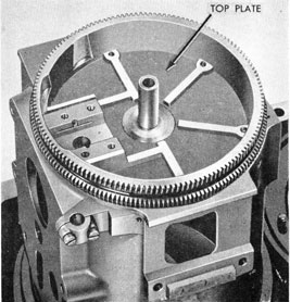
Figure 252
222
*(n) Remove outer race from top bearing holder. (WE192)
(o) Remove top bearing holder and spacing washer. (WE165)
Note: It is good practice to measure thickness of spacing washer upon removal, so that, in case of loss, a washer of proper thickness may be installed.
(p) Remove pallet pawl and linkage assembly:
(1) Remove cotter pins, spring washers, and friction springs over pallet pawls. (92)
(2) Remove cotter pin in pivot pin for bell crank, and remove pivot pin.
(92)
(3) Remove pallet pawl and linkage assembly by sliding pawls clear of their pins and bell crank clear of connection spool.
(q) Loosen clamp screw nut and remove pallet. (37)
(r) Withdraw pallet shaft and leaf spring from the inside of gyro pot. Be careful not to lose leaf spring.
(s) Remove four holding screws and pallet slide cover. (41)
(t) Remove constant-spin pipe and elbow:
(1) Remove set screw in elbow. (41)
(2) Hold elbow with pliers; insert
Figure 253
screw driver inside gyro pot; and unscrew long nipple from elbow. (72, 41)
(3) Remove long nipple, washer, and elbow.
Note: Be careful not to lose small washer between long nipple and elbow.
(u) Remove cam bevel gear, connection spool, and cam assembly.
Figure 254
(v) Remove pallet slide and pallet-holder assembly.
*(w) Remove two screws and stop for top plate. (41)
*(x) Remove two screws and remove gyro pot marker. (41)
*(y) Remove six holding screws and
remove top-plate retainer plates. (41)
*(z) Remove top plate from gyro pot.
*(aa) Remove angle fire socket, spindle, and worm from bracket for driving
spindle:
(1) Remove lock screw from socket. (37)
(2) Remove nut and socket. (40)
(3) Remove spindle and worm from bracket.
The above completes the disassembly of the gyro mechanism.
G. Gyro Mechanism
1. Thoroughly clean and inspect all parts. Remove burrs if present.
223
*2. Replace marker in gyro pot and secure with two screws. (41)
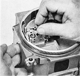
*3. Try retainer plates in their recesses in top plate to ascertain that a snug fit is obtained. Oil (C) and try top plate on its seat in gyro pot to ascertain that it is a snug fit, without binding (Fig. 252).
*4. Replace retainer plates with zero graduation in line with marker in pot. Replace holding screws for retainer plates, setting up even and tight. Check that screw heads are flush with retainer plates, and note that no burrs were raised by screw driver. Turn top plate in both directions and note if binding at any point; if so, it may be necessary to relieve by scraping surfaces of retainer plates where binding occurs. (41)
*5. Replace gyro top-plate stop and secure with two screws. Again turn the top plate in both directions and note if binding on stop. Set top plate on zero. (41)
6. Note that pallet cam is a snug fit without binding in oval cam slot in pallet slide. Note that pallet-holder adjusting screw works freely. Install pallet slide, with holder assembled, in top plate.
7. Replace cam, connection spool, and cam bevel gear assembly (Fig. 253). Turn cam bevel gear to operate pallet slide and ascertain that no binding occurs. While turning cam bevel gear, check clearance between cam and slot in pallet slide. There should be about 31/2 teeth "play" between the two parts.
8. Replace air connection for sustaining gyro:
(a) Replace long nipple by inserting it through inside of gyro pot. Hold nipple with screw driver. (41)
(b) Replace small washer and elbow over end of nipple; hold elbow with pliers and screw nipple into elbow. With nipple tight in elbow, end play should be about 0.005 inch. (41, 72)
(c) Secure elbow to nipple with set screw. (41)
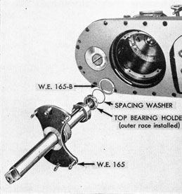
9. Replace top bearing holder for gyro (Fig. 254).
*(a) Replace outer race in top bearing holder.
(b) Slip spacing washer over threads of top bearing holder and slip WE165B over spacing washer and flange of top bearing holder. (WE165B)
(c) Start top-bearing holder in top plate by hand.
(d) Tighten top bearing-holder assembly. Remove tools after tightening. (WE165, WE165B, 205A-246)
10. Replace gyro spinning and unlocking mechanism:
Note: For disassembly, overhaul, assembly and test of spinning mechanism, see step I.
(a) Replace mechanism on gyro pot and secure with six screws. (40)
(b) Lock and unlock mechanism several times to ascertain that it is working properly. Leave mechanism unlocked. (205A-246)
Note: If mechanism is properly adjusted, the hand trip lever should be flush with the side of the pot in the locked position.
11. Align axis of gyro with axis of centering pin of gyro spinning and unlocking mechanism:
Note: The gyro must be located in the gyro mechanism in such a way that the following conditions are met when the mechanism is in its operating position: (1) The axis of the gyro must be in alignment with the axis of the centering pin in the gyro spinning and unlocking mechanism. (2) The lower outer gimbal ring center of the gyro must rest on spring button in bottom head. (3) There must be 0.006 inch to 0.011 inch clearance in gyro bottom bearing. (4) There must be 0.0025 inch to 0.005 inch clearance in gyro top bearing.
Proceed as follows:
(a) If Gyro Adjusting Stand is available, place gyro mechanism in stand; secure with holding screws and turn mechanism bottom-up. If stand is not available, support gyro mechanism bottom-up on bench. (456)
224
Figure 255
225
(b) Install gyro in mechanism:
(1) Remove gyro clamp-plate cover and gasket. (13-14)
(2) Remove gyro bottom head. (205A-246)
(3) Check to see that top plate is set on zero.
(4) Turn pallet driving gear to move cam pawls to their extreme after position (away from cam on gyro).
Figure 256
(5) If not already done, unlock gyro spinning and unlocking mechanism.
(6) Put two drops of oil (A) on gyro top bearing, using syringe.
(7) Install gyro with cam on gyro cam plate about 180 degrees from cam pawls; then rotate gyro into position.
Note: When installing gyro, take care not to damage extender in top bearing holder.
(8) Put two drops of oil (A) on gyro bottom bearing, using syringe.
(c) Install bottom head "L" with bottom-bearing holder "C" removed (Fig. 255). (205A-246)
(d) Install bottom bearing holder:
(1) Remove the adjusting body
assembly: "D", "E", "F", and "P" from the bottom bearing holder.
(92, 41, 204)
(2) Install the bottom bearing holder "C" and outer race "H".
(3) Set up on bottom bearing holder "C" until the balls "I" of both bottom and top races ("G" and "H") are in contact with the curved path of these races. (463)
Caution: Note that balls are properly centered in their races when executing above step. The balls for the lower bearing may be observed through the tapped hole in the bearing holder.
(e) Check spacing washer under top bearing holder for proper thickness:
Note 1: It is important that this washer be of correct thickness to insure the alignment of the axis of the gyro with the axis of the centering pin in the gyro spinning and unlocking mechanism when the torpedo is right-side-up. If the axes are not in alignment, the gyro will be deflected when the centering pin is withdrawn from the gyro after spinning.
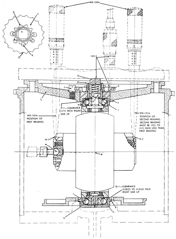
Note 2: Since the relative heights of the gyro and the centering pin "M" cannot be measured directly on their axes, the relative heights are measured indirectly, with the mechanism inverted, by taking depth measurements at corresponding points on each end of the gyro inner gimbal ring ("N-1" and "N-2" in Fig. 255. One-half the difference between these two measurements ("R", Fig. 255) will be the amount which the axis of the gyro is out of alignment with the axis of the centering pin. With the gyro mechanism in the inverted position, the two axes are intentionally adjusted "by means of the spacing washer "B" under the top bearing holder" so that they are in misalignment by 0.0025 inch to 0.005 inch: (("N-1" minus "N-2" / 2) = "R" = 0.0025 inch to 0.005 inch). This misalignment will be corrected later (step g) by giving the top bearing a clearance,
226
the amount of which is equal to "R". When the gyro mechanism is turned upright in its operating position, the gyro will drop down away from the top bearing a distance equal to "R" and the axes will then be in alignment. Proceed as follows:
(1) Lock gyro. (205A-246)
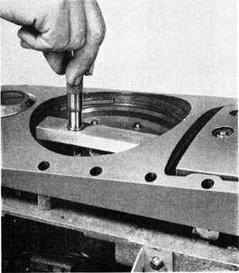
(2) Place micrometer base across seat for gyro clamp plate in pot, locating it so that depth-gage spindle will line up with outer edge of gimbal-ring locking end. (See location at
"N-1", Fig. 255). Note measurement carefully (Fig. 256). (WE190A)
(3) Reverse location of depth micrometer so that depth-gage spindle will line up with outer edge of gimbal ring free end. (See location at "N-2", Fig. 255). Note measurement carefully. (WE190A)
(4) Subtract the second reading,
"N-2", from the first reading, "N-1". The difference must be 0.005 inch to 0.010 inch. In other words, with the gyro mechanism inverted, the free end of the gyro inner gimbal ring must be 0.005 inch to 0.010 inch lower than the locking end of the inner gimbal ring. If not, the spacing washer under the top bearing holder must either be replaced with a thicker one or be reduced in thickness to meet the above condition.
(5) As an example, assume that the difference between "N-1" and "N-2" is minus 0.025 inch:
a. Unlock gyro.
b. Remove bottom head "L" (205A-246)
c. Remove gyro from mechanism.
d. Remove top bearing holder (WE165)
e. Remove washer "B" under top bearing holder.
f. With micrometer calipers, measure thickness of this washer. (WE5)
Since the difference between "N-1" and "N-2" is minus 0.025 inch, and since the difference must be (plus) 0.005 inch to (plus) 0.010 inch to be
correct, it is apparent that the free end of the gyro inner gimbal ring is higher instead' of lower than the locking end, and it will be necessary to reduce the thickness of the washer enough to bring the free end from 0.005 inch to 0.010 inch lower than the locking end. If the thickness of the washer is reduced by 0.0125 inch ((0.025 inch) / 2), the free end will be at
the same depth as the locking end. If we reduce the thickness by an additional 0.0025 inch to 0.005 inch, the free end will be the required 0.005 inch to 0.010 inch lower than the locking end; therefore, carefully reduce the thickness of the washer by 0.0150 inch to 0.0175 inch, replace washer, replace top bearing holder, and recheck measurements to make certain that 0.005 inch to 0.010 inch difference between "N-1" and "N-2" has been obtained.
(6) On the other hand, should the difference between "N-1" and "N-2"
Figure 257
be more than (plus) 0.010 inch, it is obvious that the washer "B" is too thin, in which case a new washer of the proper thickness will have to be fitted and the measurements rechecked.
227
(f) When certain that spacing washer "B" is of proper thickness, adjust bottom bearing holder to give total clearance for gyro top and bottom bearings:
Note: A total clearance of 0.0125 inch for the gyro top and bottom bearings is the most desirable. The most desirable distribution of this total clearance is 0.0025 inch for the top bearing and 0.010 inch for the bottom bearing, when the gyro mechanism is right side up. The total clearance is obtained by backing off the bottom bearing holder with the mechanism inverted. As will be seen below, the above adjustments may vary slightly because a scallop of the bottom bearing holder may not line up with the lock-screw hole, in which case the scallop nearest the screw hole, in the direction of turning, should be moved in line with the lock screw hole.
The external diameter of the bottom-bearing holder "C" is threaded 20 threads to the inch, and 20 scallops "0" are machined around a flange on its outer end for alignment with the keep screw "J". Thus it will be seen that rotating the holder one scallop in the bottom head will cause the holder (and ball race) to move up or down by 0.0025 inch ((or 1 inch) / 400). Proceed as follows:
(1) Make certain that bottom-bearing holder "C" is set up so that balls
"I" of both bottom and top races ("G" and "H") are in contact with the curved paths of these races. (See Caution under step (d), (3). (204)
(2) See that a scallop "0" on the bottom bearing holder "C" lines up with the hole for keep screw "J". If, before turning the bearing holder, the scallop nearest the locking screw hole is 1/2 scallop, or less, out of alignment with keep screw hole in direction of turning, back off to nearest scallop; then back off five additional scallops and install keep screw "J" in cotter pin. The lower and upper limits of the total clearance thus obtained will be 0.0125 inch and 0.01375 inch. (41, 92)
Figure 258
(3) If the lining up of the first scallop, in the direction of turning, takes more than 1/2 scallop, back off to nearest scallop; then back off four additional scallops and install keep screw "J" and cotter pin. The lower and upper limits of the total clearance thus obtained will be 0.01125 inch and 0.0125 inch. (41, 92)
(4) If, before turning bottom-bearing holder, a scallop is lined up exactly
228
with keep screw hole, back off five full scallops and install keep screw and cotter pin. The total clearance thus obtained will be exactly 0.0125 inch, which is the most desirable. (41, 92)
Note: From steps (2) and (3), above, it will be noted that the lower and upper limits of the total clearance, as obtained by the method out-
Figure 259
lined, are 0.01125 inch and 0.01375 inch.
(g) Adjust clearance for gyro top bearing:
Note: As explained in Note under step (e), the intentional misalignment of the axis of the gyro with the axis of the centering pin, with the gyro mechanism in the inverted position, is corrected by giving the top bearing a clearance of "R" (or ("N-1" minus "N-2") / 2) = "R"
= 0.0025 inch to 0.005 inch, Fig. 255). When the top bearing has this clearance and when the mechanism is turned right-side-up, the gyro will drop away from the top bearing holder a distance equal to "R" and the axes will then be in alignment.
Proceed as follows:
(1) Ascertain that gyro is properly seated on its upper bearing, with balls
"I" contacting curved path of the outer race "G".
(2) Install adjusting-body assembly: "D", "E", "1', and "P" in bottom bearing holder "C".
(3) Set up on adjusting body until no vertical play can be felt between upper bearing (at "G-1") and lower bearing (at "P-1"). (204)
(4) Place micrometer depth gage with the base resting on the flat face of plug "E". (See Fig. 255, also Fig. 257). (WE9)
Note: Make certain that face of plug is clean, smooth, and free from burrs before taking measurements.
(5) Measure depth to flat face on bottom bearing holder "C" and note this reading carefully. (WE9)
(6) Remove and reset micrometer depth gage, adding one-half of the difference between the reading (of WE190A) at "N-1" and "N-2", as taken in step (e). (WE9)
(7) Back out the adjusting body "D" sufficiently to permit measuring spindle on micrometer depth gage (WE9) to clear flat face on bottom bearing holder "C", when base of gage is resting flush on plug "E"; and replace depth gage on plug "E". (WE9)
(8) Screw in on adjusting body "D" until measuring spindle on depth gage just contacts the flat face on bottom bearing holder "C" with the base of depth gage flush on plug "E". This will give a clearance (at "P-1") equal
Figure 260
229
to the difference in depth-gage adjustment as reset in step (g), (6), above, and consequently a similar clearance at "G-1" with the mechanism right-side-up. (204, WE9)
(9) Secure adjustment made in step (8), above, with lock screw "K" and cotter pin. (41, 92)
Note: It is not always possible to secure adjustment obtained in step (8), above, without a slight change, as the scallop in adjusting body "D" may not line up with the hole for lock screw "K", thus making it necessary to turn the nearest scallop into alignment for lock screw. Change so made is considered negligible and is within the tolerance of allowable bearing clearances.
(h) Lock Gyro. (205A-246)
(i) Remove mechanism from Gyro Adjusting Stand or turn it right-side-up on bench. (456)
Note: As a result of the above procedures, the gyro is now in correct alignment in the gyro mechanism: (1) The axis of the gyro is in alignment with the axis of the centering pin in the gyro spinning and unlocking mechanism. (2) The lower outer gimbal ring center of gyro is resting on spring button in bottom head. (3) The
Figure 261
Figure 262
gyro bottom bearing has a clearance of 0.006 inch to 0.011 inch (total clearance of 0.01125 inch to 0.01375 inch minus top bearing clearance of 0.0025 inch to 0.005 inch). (4) The gyro top bearing has a clearance of 0.0025 inch to 0.005 inch.
*12. Replace angle fire spindle, socket, and worm on bracket for driving spindle (Fig. 258).
(a) Place worm in bracket, with holes in alignment.
(b) Insert spindle, lining up key on spindle with keyway in worm.
(c) Replace socket on spindle and secure with nut and lock screw. (40, 37)
13. Replace bracket for driving spindle (Fig. 258).
230
Figure 263
(a) Replace bracket on gyro pot, making certain that worm meshes with top plate.
(b) Replace two holding screws for bracket and tighten about halfway. (49)
(c) Replace steering-engine valve guard and secure loosely with two screws. (40)
(d) Tighten evenly all four screws for bracket. (49)
(e) Oil (C) bearing for angle fire worm and turn top plate with worm to extreme travel in both directions. Note if there is binding at any point; binding should be relieved by stoning. Turn top plate to zero.
(a) Replace proper lower spacing washers on depth-mechanism casing.
(b) Replace bracket over spacing washers and over holes in bracket for driving spindle.
(c) Replace proper upper spacing washers on bracket over holes in depth-mechanism casing.
(d) Replace screws which secure bracket to depth-mechanism casing.
Leave screws loose. (161, 408)
(e) Replace screws which secure
bracket to bracket for driving spindle. Leave screws loose. (49)
(f) Tighten all screws evenly.
(49, 161, 408)
15. Oil (C) and replace driving spindle in bracket, with teeth on driving pinion in mesh with teeth on cam bevel gear. Replace bearing cap on bracket and secure with six holding screws. Turn spindle and cam bevel gear and note if they turn freely without binding. (41)
Note: If pertinent parts have been renewed, it may be necessary to fit them to prevent binding.
16. Replace pallet driving gear and bearing (Fig. 259):
Note: Oil (C) all parts during assembly.
(a) Install pallet driving gear in bearing.
(b) Replace bearing cap and secure with four holding screws. Note that driving gear turns freely in its bearing.
(41)
(c) Replace spring and plunger for driving gear bearing.
(d) Replace connection shaft in end of pallet driving gear; install pallet
Figure 264
231
driving-gear and bearing assembly in pallet driving-gear bracket, guiding after end of connection shaft into square hole in driving spindle.
(e) Replace the two trunnion pins with notched sides facing up, and secure with trunnion-pin keep screws. (41)
(f) Turn pallet driving gear and note if there is any binding.
17. Inspect pins in pallet-slide cover and make certain that they are firm and straight. Replace cover and secure with four screws. After tightening screws, turn pallet driving gear to operate pallet slide, and note that there is no binding. Move pallet slide to its extreme after position. (41)
18. Replace pallet shaft with cam pawls and spring, noting that:
(a) There is 0.001 inch to 0.003 inch total side clearance between cam pawls and cam on gyro cam plate. (Check this clearance before replacing pallet shaft assembly in pallet holder).
(b) Cam pawls fit tightly over end of pallet shaft, with no lost motion.
(c) Leaf spring is in place on shaft and is under slight compression, as evidenced by its 'bowed" shape when installed.
(d) The 5/32-inch diameter of upper end of pallet shaft extends just above upper end of bearing in pallet holder, so that pallet shaft will have 0.001 inch to 0.002 inch vertical clearance when pallet is assembled.
(e) Pallet shaft is a lap fit with unrestricted rotary movement in bearing in pallet holder.
19. Replace pallet on pallet shaft (Fig. 260) noting that:
(a) Pallet is free of burrs, that edges are sharp and square, and that blade is of proper thickness (0.063 to 0.065 inch).
(WE5)
(b) Pallet fits snugly on pallet shaft.
(c) Pallet is centered approximately on pallet shaft.
(d) Pallet is installed and clamped on pallet shaft, so that there is a slight vertical play of shaft (0.001 inch to 0.002 inch). (41)
20. Adjust clearance between cam on
gyro and cam pawls and center pallet:
(a) Ascertain that gyro is locked. (205A-246)
(b) Ascertain that top plate is set on zero.
Figure 265
(c) Turn pallet driving gear slowly to move cam pawls in toward cam on gyro cam plate. Make certain that cam pawls straddle cam. If they do not, turn top plate to center cam pawls around cam, and reset pot marker. (41)
(d) With cam pawls straddling cam, center pallet between pins on pallet-slide cover. Clamp adjustment by tightening screw and nut on pallet. Check adjustment after tightening. (WE2A, 41)
(e) Loosen clamp screw for pallet holder (Fig. 261). (41)
(f) Unlock gyro.
(g) Move cam pawls in toward cam on
gyro cam plate by turning pallet driving gear. Swing gyro slowly in azimuth.
At any indication of cam pawls binding
on cam, turn pallet-holder adjusting
screw to give more clearance (Fig. 262).
(145)
232
(h) With cam pawls in extreme forward position, continue to move gyro slowly in azimuth and check clearance between pallet and pins on pallet-slide cover when pallet is in extreme right and left positions toward pins. The clearance for both positions of pallet must be equal and must be between 0.010 inch and 0.012 inch. (Fig. 263). If not, turn adjusting screw for pallet holder. When the clearances are equal and are between 0.010 inch and 0.012 inch, swing gyro slowly through an angle of 360 degrees in azimuth and make certain that it swings freely, with no binding in any position. Contact between the cam pawls and the ridges on the gyro cam plate should be barely perceptible. After adjustment has been made, tighten clamp screw for pallet holder and lock gyro.
(145, WE2A, 41, 205A-246)
21. Replace pallet pawl and linkage assembly on pallet-pawl pins:
(a) Turn pallet driving gear to bring pallet forward.
(b) Clean and inspect pallet pawls. Edges must be sharp.
(c) If previously removed, assemble adjustable eye connection to port pallet pawl and bell crank, and secure with cup washers and cotter pins. (92)
(d) Replace pallet pawl assembly on pallet-slide cover pins, engaging bell crank in spool.
Note: Pallet pawls must be a snug fit, without binding, on pallet-slide cover pins.
(e) Hold pallet pawls in neutral position and turn pallet driving gear until pallet is in the extreme after position. Measure clearance between pallet and pallet pawls. This clearance should be 0.003 to 0.005 inch between either side of pallet and pallet pawl being measured (Fig. 264).
Note: If clearance obtained above is too small, stone pallet pawls. Edges must be sharp and free of burrs. If clearance is too large, replace parts as necessary.
(f) Line up holes in bell crank with
holes in pallet-slide cover; replace bell crank pin and secure with cotter pin.
(92)
(g) Replace friction springs and washers on pallet pawls and secure with cotter pins. (92)
22. Replace valve rock-shaft assembly:
(a) Oil (C) and replace two friction springs and two buttons in valve rock-shaft bearing.
(b) Note that rock-shaft arm, counterweight, and valve connection arm are tight.
*(c) If previously removed, assemble adjusting head on rock shaft. (41)
(d) Line up pin on after end of rock-shaft arm in annular groove on connection spool, and install the rock-shaft assembly in its bearing in bracket for driving spindle.
(e) Replace cap and secure with two holding screws. (41)
23. Install steering engine on gyro pot and secure with two holding screws. Do not connect valve link at this point. (49)
Note: For disassembly, assembly, overhaul and test of steering engine, see step K.
24. Adjust linkage from connection spool to steering-engine valve:
(a) Move steering-engine valve all the way out; move valve connection arm in the same direction and note if it moves farther than valve.
(b) Move steering engine valve all the way in; move valve connection arm in the same direction and note if it moves farther than valve.
Note: If valve connection arm moved a greater distance than valve in either direction, the connection may be considered properly lined up. If the valve, however, has a further movement than the valve connection arm in either direction, it will be necessary to readjust by moving the valve connection-arm adjusting head on the rock shaft. If this adjustment is insufficient, it will be necessary to realign the valve connection arm by bending.
233
(c) Connect valve connection arm to steering engine valve link. (205A-246)
(d) Move steering-engine valve all the way forward. In this position, note vertical clearance between connection spool and pallet-slide cam.
(e) Move steering engine valve all the way aft. In this position note vertical clearance between connection spool and the cam bevel gear.
Note: If linkage from connection spool to steering-engine valve is correctly adjusted, clearances obtained in steps (d) and (c), above, should be approximately the same.
25. Adjust clearance between end of pallet and pallet pawls:
(a) With gyro locked, turn driving gear to move pallet clear of pallet pawls; turn pallet to port; turn driving gear to move pallet to its extreme after position and adjust clearance between the end of the pallet and the port pallet pawl to between 0.003 inch and 0.004 inch. To make this adjustment, loosen clamp screws and turn adjusting screw for the eye connections until correct clearance is obtained. Tighten clamp
screws (Fig. 265). -
(41, 145, WE161, WE161A)
(b) Turn driving gear to move pallet clear of pallet pawls; turn pallet to starboard; turn driving gear to move pallet to its extreme after position and adjust clearance between the end of the pallet and the starboard pallet pawl to between 0.003 inch and 0.004 inch. To make the adjustment, loosen clamp screws and turn the pallet linkage-adjusting screw until correct adjustment is obtained. Tighten clamp screws.
(41, 145, WE161, WE161A)
(c) After the above adjustments are made, check them to make sure that no binding exists between pallet and either pawl and that clearance between pallet and pawl being measured is 0.003 inch to 0.005 inch (see Fig. 264). (WE2A)
26. Check centering of pallet and top plate:
(a) Check to see that top plate is on zero.
(b) Ascertain that gyro is locked.
(c) Place and hold pallet pawls in neutral position.
(d) Turn pallet driving gear and note if cam pawls straddle cam on gyro. If cam pawls do not straddle cam, turn top plate until they do, and re-set pot marker.
(e) After top plate has been centered, turn pallet driving gear and note if pallet passes between pallet pawls. If pallet touches either pallet pawl instead of 'Passing between them, re-center pallet.
(f) If it was necessary to adjust top plate or pallet in steps (d) and (e). repeat step 25.
27. Test friction in linkage from pallet pawls to steering-engine valve:
Note: In order to prevent fluttering of the linkage from pallet pawls to steering engine valve, with consequent erratic movement of this valve, two spring buttons are installed in the valve rock-shaft bearing. The springs for these buttons should be adjusted to require the application of not less than 10 ounces, nor more than 12 ounces on the valve end of the valve connection arm to cause the linkage to move full-throw in either direction.
(a) Disconnect valve link from valve connection arm. (205A-246)
(b) Turn driving gear to clear pallet from pallet pawls.
(c) Move valve connection arm all the way aft with feather gage, contacting the lower end of valve connection arm. Measure push required to move linkage for full throw. (MF7)
(d) Move valve connection arm all the way forward and repeat test for reverse throw. (MF7)
Note: As previously stated, the linkage should move full-throw by the application of a 10- to 12-ounce force on the lower end of the valve connection arm. If less than a 10-ounce force is required to move linkage, it will be necessary to remove the rock shaft and stretch the springs under the spring buttons in the
234
rock-shaft bearing, assemble, and repeat test until correct readings are obtained.
(e) Re-connect valve link to valve connection arm. (205A-246)
28. Check clearances between end of pallet blade and pallet pawls with air on steering engine:
(a) Unlock gyro.
(b) Connect low-pressure air line (approximately 450 p.s.i.) to steering engine and turn on air. (141A)
(c) Turn driving gear to clear pallet from pallet pawls.
(d) Swing gyro in azimuth to rove pallet to port; turn driving gear to move pallet to its extreme after position. Note performance of steering engine.
(e) Turn pallet driving gear to clear pallet from pallet pawls.
(f) Swing gyro in azimuth to move pallet to starboard. Turn pallet driving gear to move pallet to its extreme after position. Note performance of steering engine.
Note: Full, snappy throws of steering engine should be obtained with the above procedure; if not, readjust clearances between end of pallet blade and pallet pawls.
(g) After satisfactory test has been made, disconnect air line from steering engine; remove gyro; replace bottom head, gasket, and gyro clamp plate cover.
(141A, 205A-246, 13-14)
Note: If a Gyro Adjusting Stand is available, a running test will be made on the Gyro Mechanism and Gyro (see step H). If this stand is not available, disconnect and remove steering engine in step 28, (g), above. The gyro and gyro mechanism should then be given a running test in the Afterbody Adjusting Stand. (See Section 10).
29. Replace tension rod and valve lever assembly on depth mechanism:
(a) Assemble pendulum tension rod on its pivot in port pendulum arm and secure with cotter pin. (72)
(b) Secure depth-engine valve operating lever to bracket for driving spindle and fulcrum pin and cotter pin. (40, 72)
H. Running Test of Gyro and Gyro Mechanism
Note: The gyro and gyro mechanism should be given a running test in the Gyro Adjusting Stand, if this stand is available. The procedure given below outlines the test.
1. Place gyro mechanism in stand and secure with holding screws. (456)
2. Install gyro in mechanism:
Note: The gyro must be in proper working order. (See steps L and M.)
(a) Remove gyro clamp plate cover and gasket. (13-14)
(b) Remove gyro bottom head. (205A-246)
(c) Check to see that top plate is set on zero.
(d) Turn pallet driving gear to move cam pawls away from cam on gyro.
(e) If not already done, unlock gyro spinning and unlocking mechanism.
(f) Put two drops of oil (A) on gyro top bearing, using syringe.
(g) Install gyro with cam on gyro
Figure 266
235
Figure 267
cam plate about 180 degrees from cam pawls; then rotate gyro into position.
Note: When installing gyro, take care not to damage extender in top bearing holder.
(h) Put two drops of oil (A) on gyro bottom bearing, using syringe.
(i) Install gyro bottom head.
(205A-246)
Note: While installing bottom head, rotate gyro to make certain it does not "hang up" on either bearing.
3. Lock gyro. (205A-246)
4. Turn mechanism right-side-up and set stand on zero.
5. Connect high-pressure air line (2800 p.s.i.) to gyro spin nipple. (229)
6. Connect low-pressure air line (450 to 500 p.s.i.) to steering engine. (141A)
7. Remove blank nut from "T" connection on gyro reducer and connect gage pipe to nipple. (141A)
Figure 268
8. Turn on air to steering engine and adjust gyro reducer to deliver 100 p.s.i.
(48, 155)
Note: When a torpedo is running, pressure is built up in the afterbody. This pressure has a subtractive effect on the pressure from the gyro reducer. Setting the gyro reducer to deliver 100 p.s.i. for the stand test, simulates actual running condition of the torpedo. After the stand test, the gyro reducer is set to deliver 125 p.s.i. (See step 14).
9. Turn on motor which drives pallet mechanism.
Figure 269
236
Figure 270
10. Throw over the lever handle of the quick-opening valve in the high-pressure line and throw back as soon as the gyro unlocks.
11. Move stand off zero and note position of stand pointer when steering engine makes a stroke.
12. As soon as engine moves/ reverse direction of stand and note position of stand pointer at second engine stroke.
Note: The total movement in azimuth of the stand between strokes of the engine should be not more than four-tenths of a degree, and the mid-point of this travel in
Figure 271
azimuth between strokes should be within one-tenth of a degree from the stand zero.
13. Turn off motor which drives pallet mechanism.
14. Adjust gyro reducer to deliver 125 p.s.i. (48, 155)
15. Turn off air; disconnect air pipes; replace blank nut on "T" connection on gyro reducer and permit gyro to run down by itself. (141A, 229)
Figure 272
16. Remove gyro; replace gyro bottom head; replace gyro clamp plate cover and gasket and remove mechanism from stand.
(205A-246, 13-14, 456)
17. Should the assembly fail to operate within the specified limits given in Note under step 12, the following should be investigated as sources of trouble:
(a) Lost motion between top plate and gyro pot.
(b) Top plate not centered.
(c) Wrong gyro height.
(d) Gyro not properly balanced. (e) Bad balls in gyro bearings.
Steps D to G, above, cover the overhaul, assembly and test of the depth mechanism and gyro mechanism. Steps H to M, below, cover the disassembly, overhaul, assembly, and test of component unit,: of these mechanisms.
I. Gyro Spinning and Unlocking Mechanism
Note: In step F-1, the gyro spinning and unlocking mechanism was given a test. If the mechanism did not pass test
237
satisfactorily, it must be disassembled, overhauled, assembled, and tested in accordance with procedure outlined below:
*1. Disassemble:
(a) Hold spinning gear in vise between copper jaws and unscrew spinning turbine from seining shaft. Remove thrust washer. (25)
(b) Remove cotter pin from pin for spring guide pin and remove spring guide pin with spring. (92, WE178)
(c) Remove nut and washer from spring bell crank end of rock shaft. (141A)
(d) Remove spring bell crank. (It may be necessary to pry off with two screw drivers).
(e) Remove nut and washer from valve bell crank end of rock shaft. (141A)
(f) Remove pinion between upper and lower racks.
(g) Remove rock shaft, valve bell crank, and locking lever.
(h) Remove two screws and nipple holder from spinning-gear frame.
(i) Remove cotter pin from lower holding screw; remove holding screws; and remove front plate assembly. (72, 40)
Note: Exercise care not to bend dowel pins when removing front plate assembly.
Note: Take care not to bend dowel pins in upper rack.
(k) Remove centering pin.
(l) Remove controlling sleeve assembly from spinning shaft sleeve.
(m) If necessary to remove spinning gear from controlling sleeve, prick-punch centers of rivets in face of spinning gear, drill out rivets, and remove spinning gear and split retainer washer.
Figure 275
238
(n) Remove sleeve (and spinning shaft) from frame.
(o) Remove screws, upper and lower gear center plates, pinion, worm wheel, and gear from spinning-shaft sleeve.
(41)
(p) Remove spinning shaft and thrust washer from spinning-shaft sleeve.
Figure 276
(q) Remove screws and upper and lower bearing caps (for hand trip lever) from frame. (41)
(r) Disconnect spring from hand trip lever and remove hand trip lever. (92)
(s) Remove unlocking bar.
(t) Remove lower rack. (It may be necessary to loosen rack by tapping with a soft hammer).
(u) Remove hinge (holding) screw,
Figure 277
cotter pin from fulcrum pin for spring lever, and remove duration-adjusting element assembled. (49, 92)
(v) Remove unlocking rack.
(w) Disassemble duration-adjusting element:
(1) Loosen hinge clamp screw. (41)
(2) Remove cotter pin and nut from spring rod. (92, 205A-246)
(3) Slide spring rod with spring lever out of spring case.
(4) Unscrew spring case from hinge.
Figure 278
(Note location of hinge on spring case prior to unscrewing, in order that assembly may be made without affecting the spin duration).
(5) Remove spring case nut, washer
and spring. (161)
(x) Remove gyro spin nipple (with restriction), washer, and impulse valve from front plate. (18)
The above completes the disassembly of
the gyro spinning and unlocking mechanism.
*2. Overhaul, assemble, and test:
(a) Thoroughly clean and inspect all parts. Remove burrs if present. Apply oil (C) to parts.
(b) Chase threads and reseat seat on gyro spin nipple. (WE94, WE83)
(c) Reseat seat for impulse valve and grind in valve (Fig. 266). (WE164, 40)
(d) Lap impulse valve to its seat, using oil (C). (40)
239
(e) Note that restriction is clear (0.180 inch), place a new washer on seat for gyro spin nipple; insert impulse valve and screw nipple in place in front plate. (18)
Note: When nipple is set up tight, square section of nipple must be lined up at right angles to finished surface on inner side of front plate, in order that holder for nipple may be lined up with screw holes when assembled.
(f) To test impulse valve for leaks, connect nipple to a high-pressure air source, immerse front plate in water, and watch for bubbles (Fig. 267). (229)
(g) Replace unlocking bar and slide it back and forth in its slide on mechanism frame and note if excessive play is present. This bar must be a close fit and yet work freely without binding (Fig. 268).
(h) Replace hand trip lever and secure spring. (92)
(i) Replace lower rack.
(j) Replace upper and lower bearing caps for hand trip lever and secure with screws. Note that no binding occurs between upper bearing cap and unlocking bar. (41)
(k) Replace unlocking rack. Note that rack moves without binding or excessive play.
(l) Replace duration-adjusting element (Fig. 269):
(1) Replace hinge and clamp screw on frame and secure with holding screw. (49)
(2) Replace spring rod and spring lever, engaging lever in unlocking rack and on fulcrum pin. Secure with cotter pin in fulcrum pin. (92)
(3) Replace washer, spring, and washer in spring case; and replace spring-case nut. (161)
(4) Screw spring case into hinge to location, as noted in disassembly.
(5) Tighten hinge clamp screw. (41)
(6) Replace nut on spring rod. Tighten nut to remove all lost motion from assembly, and replace cotter pin.
(205A-246, 92)
(7) Move unlocking rack back and
forth. If binding occurs, back off slightly on hinge screw. (49)
(m) Assemble bell cranks and locking lever on rock shaft, and note if any play exists between the parts. If play is found, it must be remedied, since play will prevent proper locking. Remove parts from rock shaft.
Figure 279
(n) Insert locking lever into recess in mechanism frame, with "X" on locking lever facing toward the bell crank end.
(o) Insert rock shaft into frame, moving locking lever to line up key with keyway. Push rock shaft into place (Figs. 270 and 271).
(p) Insert centering pin into lower rack and make certain that it moves freely without excessive play. Remove centering pin.
Note: If centering pin does not move freely in lower rack, remove burrs and irregularities by stoning. Do not use lapping dust or emery.
(q) Replace upper gear center plate on spinning-shaft sleeve, leaving screws loose. (41)
(r) Insert spinning shaft and thrust washer into sleeve. Replace worm wheel and gear, meshing worm wheel with worm on spinning shaft. Install pinion in mesh with small gear on worm wheel.
240
Figure 280
(s) Replace lower gear center plate with centers meshing in gears, and secure with screws (Fig. 272). Remove burrs extending from screw heads. See that cotter pins are installed through gear centers in lower gear center plate. See that spinning shaft moves freely in mesh with gear train. See that all screws are tight. (41)
(t) If previously removed, replace spinning gear on controlling sleeve; insert split retaining washer and rivet in place with six small brass rivets. Note that
spinning gear moves freely on controlling sleeve after riveting.
(u) Replace (temporarily) controlling sleeve assembly in spinning-shaft sleeve assembly, lining up punch marks on spinning shaft and spinning gear.
(v) Replace (temporarily) upper rack in controlling sleeve and secure with holding screw. (37)
Note: Take care not to bend dowel pins.
(w) Test above assembly for freedom of rotary and longitudinal movement. When satisfied that no binding or lost motion exists, remove upper rack and controlling sleeve assembly. (37)
(x) Place spinning-shaft sleeve assembly in frame and insert controlling sleeve assembly, lining up punch marks (Fig. 272).
(y) Replace upper rack in controlling sleeve and secure with holding screw. Prick-punch holding screw to prevent it from loosening up (Fig. 273). (37)
(z) Replace centering pin.
(aa) Replace front plate assembly, guiding upper rack into slot, and secure with three screws. Replace cotter pin in lower screw. (41, 92)
(ab) Replace valve bell crank and secure with washer and nut (Fig. 274).
(141A)
Figure 281
241
(ac) Push valve bell crank to its extreme after (unlocked) position. Push spinning gear to move spinning-shaft sleeve assembly to its extreme after (unlocked) position. Insert pinion in mesh with upper and lower racks and through slot in valve bell crank. With steel scale, measure distance that spinning gear projects from face of mechanism frame. This distance should not exceed 13/32 of an inch to face of spinning gear. A distance in excess of 13/32 of an inch indicates that pinion gear is improperly meshed in upper and lower racks (Fig. 275). (WE8)
(ad) Replace spring bell crank and secure with washer and nut (Fig. 274).
(141A)
(ae) Replace spring guide pin, with spring, and secure with cotter pin (Figs. 276 and 277). (WE178, 92)
(af) Hold spinning gear between copper jaws in vise. Replace washer, and screw spinning turbine in place on spinning shaft (Fig. 277). (25)
(ag) Replace nipple holder on spinning-gear frame and secure with two screws (Fig. 278). (40)
(ah) Lock and unlock mechanism several times and note that parts move freely without binding and that mechanism unlocks smartly. (205A-246)
(ai) Check number of revolutions required to unlock mechanism:
(1) Lock mechanism. (205A-246)
(2) Draw a pencil mark on spinning turbine for reference and count number of turns of turbine required to unlock (should be 58 to 62 turns).
(3) If more than 62 turns of turbine are required to unlock mechanism, loosen clamp screw on hinge and turn spring case clockwise until correct number of turns is obtained. If fewer than 58 turns are required to unlock mechanism, turn spring case counterclockwise until correct number of turns is obtained (Fig. 278). (41)
(4) After proper adjustment is obtained, tighten clamp screw on hinge. (41)
Figure 282
The above completes the overhaul, assembly, and test of the gyro spinning and unlocking mechanism.
J. Gyro Reducing Valve
Note: The gyro reducing valve should be given the following test to facilitate inspection of condition during overhaul.
1. Test prior to assembly:
(a) Connect reducing valve inlet connection to pipe from 1000 p.s.i. gage on Gyro Reducing Valve Testing Panel.
(24)
(b) Connect reducing valve outlet connection to pipe leading to restriction pet cock and 200 p.s.i. gage. (24)
(c) Close restriction pet cock to 200 p.s.i. gage.
(d) Remove lock nut, adjusting nut, washer, and spring from reducing valve.
(48, 155)
(e) Turn on air, and control pressure at 450 p.s.i on the 1000 p.s.i. gage by means of the control valve.
Figure 283
242
Note: If the reducing valve does not leak, no pressure will be recorded on the 200 p.s.i. gage; the valve may be considered satisfactory on this test, however, if only a small leak (up to 20 p.s.i.) is present.
(f) Close control valve; replace spring, washer, and adjusting nut on reducing valve; and open restriction pet cock.
Figure 284
(g) Set up on adjusting nut, and with 400 to 450 p.s.i. on the 1000 p.s.i. gage, adjust the nut until the 200 p.s.i. gage registers 125 p.s.i. (Fig. 279). (155)
(h) Shut off air and turn on again several times to ascertain that valve functions properly and that adjustment is correct. Tap reducing-valve body slightly and note if pressure crawls up or down. A properly fitted reducing valve will not be affected by tapping.
(i) Replace and tighten lock nut, holding adjusting nut from turning. (48, 155)
(j) Disconnect and remove reducing valve from testing panel. (24)
2. Disassemble:
Note: If the above test shows that the operation of the reducing valve is not satisfactory, disassemble the reducing valve as outlined below:
(a) Remove lock nut and adjusting nut. (48, 155)
(b) Remove spring and washer.
(c) Remove diaphragm nut. (25)
(d) Remove cotter pin, nut, and washer for diaphragm. (205A-246, 92, 155)
(e) Remove diaphragm and reducing-valve stem.
3. Overhaul, assemble, and test:
(a) Clean and inspect reducing-valve body, paying particular attention to valve-stem hole. Lap hole if necessary.
(WE177)
(b) Clean and inspect reducing-valve stem. Note that lapped surface is free of scratches or burrs. If stem is too loose in body, replace by lapping in a new stem. (WE139)
(c) Clean, inspect, and renew diaphragm if it shows indication of having been strained.
(d) Place a small amount of lapping compound around seat for diaphragm. Screw diaphragm nut down against this seat and rock tool back and forth, thus removing any high spots which may be found on this seat. Remove nut and wash seats clean. (25)
(e) Replace diaphragm:
Note: It is desirable to turn a hardwood stick to the diameter of the valve stem, with one end turned down to fit hole in center of diaphragm.
Figure 285
(1) Slip hardwood stick through hole in reducing valve body.
(2) Replace diaphragm on its seat in valve body, holding it central on small end of hardwood stick.
(3) Replace diaphragm nut and set up tight. (25)
(4) Remove hardwood stick.
(f) Replace valve stem:
243
Figure 286
(1) Wipe small amount of oil (D) on the lapped portion of valve stem.
(2) Insert valve stem into valve body.
(3) Secure to diaphragm with washer, nut, and cotter pin.
(205A-246, 155, 92)
(a) Mount steering engine on Leakage Test Stand and connect test lead to it. (49, 141A)
(b) Turn on air until high-pressure gage reads 500 p.s.i.
(c) Move valve and take low-pressure gage readings when piston is at each end of the cylinder (Fig. 280). These readings should lie between 250 and 325 p.s.i. and should not differ from one another by more than 20 p.s.i.
Figure 287
(d) Rotate piston in 90-degree increments, repeating step (c) of test at each of the four rotational positions of the piston.
Note: When rotating the piston, move it back and forth with the valve, so as not to score the cylinder.
(e) Test cylinder head, inlet nipple, strainer fittings, and piston-rod packing gland for leaks, using oil (C).
Note: The piston should always be at the opposite end from that being tested for leaks, so that the end being tested will be under air pressure.
(f) Move valve so that piston moves into the engine cylinder (forward position). Note that there is clearance between the piston fork and the packing-gland nut.
(g) Check length of piston stroke as follows: Measure distance from piston fork to packing-gland nut. Move valve to
Figure 288
244
throw piston a full stroke the other way. Again measure distance from piston fork to packing-gland nut. The difference between these two measurements is the stroke and should be between 0.438 and 0.448-inch. (WE8)
Figure 289
Note: If the stroke is not in the above range, the spacing washer will have to be changed. (See step 4, below).
(h) Turn off air.
(i) Test tightness of packing by using a push balance to move the piston (Fig. 281). The reading should be between 15 and 25 pounds. (98)
(j) Disconnect test lead from engine and remove engine from test stand.
(141A, 49)
The above test is made to facilitate inspection of condition during overhaul.
2. Disassemble engine:
(a) Loosen fork clamp screw. (49)
(b) Screw off fork. Scribe position before removal and count turns.
(c) Remove gland lock screw. (41)
(d) Remove gland. (18)
(e) Remove packing. (482)
(f) Hold connection end of valve with pliers; unscrew valve stop screw; remove valve stop and remove valve. (92, 37)
(g) Remove locking screw and washer from cylinder head. (41)
(h) Remove cylinder head and copper washer. (407)
(i) Remove piston and adjusting washer, using screw driver to push piston out of cylinder.
(j) Remove strainer holder cap, washer, and strainer. (402)
(k) Immerse all parts, except packing, in grease solvent and blow dry with air.
(l) Immerse new packing in oil (D) until ready for use.
3. Inspect parts for wear and defects:
(a) Note if any scratches or small scores appear on inside walls of steering-engine cylinder.
(b) Examine piston rod for burrs or scratches. Examine piston rings for wear; piston rings should show even wear throughout their convex surfaces. There should be no tendency for rings to bind or stick in grooves; butt ends should be free, with no noticeable clearance.
(c) Observe butt clearance by inserting piston with rings in cylinder, noticing rings as they enter cylinder; if butt clearance is noticeable by eye, the rings are worn too much and should be replaced. (213)
(d) Examine valve hole for burrs or scratches.
Figure 290
(e) Examine valve for burrs or scratches.
(f) Check valve for alignment, using straight edge or surface plate.
(g) Examine strainer and strainer holder.
*4. If engine stroke is not correct as noted
245
in step 1-(g) above, remedy by facing off or renewing adjusting washer.
*5. Lap out any irregularities, scratches, or burrs found in engine cylinder, using lapping compound only if necessary. Lap to final size, using oil (C) (Fig. 282).
(WE153, 41)
*6. Lap out any burrs or scratches found on piston rod, using lapping compound sparingly if necessary. (WE204, 41)
*7. Fit new piston rings:
(a) Remove worn rings from piston.
(b) Adjust male lap, WE153, to fit cylinder snugly. (WE153, 41)
(c) Measure diameter of WE153 after adjusting to fit cylinder. (WE6, WE153)
(d) Adjust WE153 so that it is 0.002 inch larger in diameter than bore of cylinder. (WE153, 41. WE6)
(e) Insert WE153 into female lap, WE154, and adjust female lap, WE154, to fit WE153 snugly (Fig. 283).
(WE153, WE154, 41)
(f) Select new rings and see that they are free from burrs. If possible, select rings that will fit WE154 without dressing down the butt ends. (WE154)
Note: If necessary to remove metal on butt ends to fit rings into lap, WE154,
Figure 291
use a small flat file, and finish by stoning. Remove burrs after filing and stoning.
(g) Measure width of rings. (WE5)
Note: The average ring before fitting will measure about 0.100-inch.
(h) Slip rings, one at a time, over lap holder, WE156, and rub down to a width
of 0.096-inch against a piece of No. 0 emery cloth laid on a smooth and level surface. (WE156, WE5)
(i) Finish lapping rings against smooth side of combination oil stone (Fig. 284), trying rings in grooves on piston until a
Figure 292
snug fit without binding is obtained.
(WE156)
(j) After lapping, wash piston and rings thoroughly with a suitable grease solvent and blow dry with air.
(k) Place all rings in female lap.
(WE154)
(l) Remove clamp bolt, washer, and sleeve on lap-plug holder, WE155; insert this tool through piston rings in WE154; slip washer over end of WE155 and secure tight with clamp bolt.
(WE154, WE155, 144)
(m) Remove WE155 with rings, and examine all rings to see that butt ends are closed together.
(n) Lap rings in WE154, using the medium-fine grade of compound (Fig. 285). Gradually tighten up on lap until rings are 0.001-inch larger in diameter than bore of cylinder.
(WE154, WE155, WE6, 41)
246
Figure 293
(o) Change to fine grade of lapping compound and finish lapping rings with oil (C) until they reach the inside diameter of the cylinder.
(WE154, WE155, WE6, 41)
Note: Remove lapplug holder, WE155, from WE154 occasionally during lapping and note if entire outside surface of each ring contacts lap. If there is any doubt about a ring not lapping out, it is best to replace such ring before proceeding any further, as the whole set must be finished lapped together.
(p) After rings have been lapped to size of cylinder, wash clean with oil (C) and try WE155, with rings in cylinder. If rings fit too snugly, do not attempt to force them into cylinder, but replace in WE154 and continue to lap and try again until fit is obtained.
(WE154, WE155, 213)
(q) Remove rings from WE155; wash thoroughly with grease solvent and assemble them on piston. (WE155, 144)
*8. Lap valve hole in engine body:
(a) Adjust male lap, WE125, to size of valve hole in body. (WE125)
Note: In making this adjustment, great care must be taken not to mar end of lap. Using a piece of copper stock having a 3/16-inch hole, line up end of lap in this hole and tap lap handle lightly with a small bronze hammer, trying lap in hole for valve until final adjustment is obtained.
(b) If any burrs or scratches are found in valve hole, use a small quantity of fine lapping compound, applying evenly over surface of lap. (WE125)
Note: In lapping, move lap with a turning and reciprocating motion over total length of hole to obtain a uniform diameter throughout its length. Do not lap more than necessary to remove burrs and scratches.
(c) Carefully wash lapping material off lap and out of hole with a grease sob vent and blow out carefully with low-pressure air.
(d) Lap hole with oil (C) until it shows a well polished surface (Fig. 286). (WE125)
(e) Wash hole and lap with grease solvent and blow dry with low-pressure air.
*9. Fit new valve:
(a) Measure diameter of lap, WE125, after finish-lapping hole in body, as done in step 8- (d), above. Pick out a spare valve about 0.0025-inch larger than this diameter. (WE125, WE5)
(b) Apply lapping compound sparingly on surfaces to be lapped, and insert valve in female lap, WE126. Regulate adjusting screws in lap for proper friction and proceed to lap, moving valve in lap with a turning and reciprocating motion throughout its length (Fig. 287).
(WE126, 41)
(c) Remove, examine, and measure diameter occasionally during lapping. Change to finest grade of lapping compound when valve measures 0.0005-inch large, and lap down to size.
(WE126, WE5, 41)
(d) Wash compound from lap and valve with grease solvent and blow dry with air.
(e) Finish lapping to a polish with oil (C). (WE126)
247
Note: The valve must be as nearly perfect a fit in body as is possible to get, without any appreciable friction when finished.
(f) After lapping, wash lap and valve with grease solvent and blow off with low-pressure air.
10. Assemble engine (Fig. 288):
(a) Oil (C) parts, except packing.
(b) Place butt ends of piston rings 180 degrees apart on piston and insert piston and adjusting washer into cylinder, being careful not to mar parts. (213)
(c) Replace and tighten cylinder head and copper washer. Renew washer if necessary. (407)
(d) Replace locking screw and washer for pushing packing into place.
(e) Renew packing, being careful not to mar piston rod by using any sharp tools for pushing packing into place.
(f) Install packing gland and set up hand-tight.
(g) Screw piston fork on piston to scribe mark, using same number of turns as on disassembly. Replace and tighten clamp screw. (49)
(h) Tighten up on packing gland gradually, turning and pushing piston back and forth by hand to work packing around
piston rod. (18)
(i) Replace gland lock screw. (41)
(j) Insert valve in engine body and secure with valve stop and stop screw. (92, 37)
(k) Make certain strainer is clean and replace it in strainer holder.
(l) Replace washer and strainer holder cap. Tighten cap. (402)
11. Test assembled steering engine (see Step K-1).
The above completes the disassembly, overhaul, assembly, and test of the steering engine.
L. Gyroscope Mk 12-3-Disassemble
1. Test gyroscope for leaks prior to disassembly:
(a) Place gyro in Gyro Balancing Fixture. Insert cam-plate end in bearing holder having air connection.
(b) Connect low-pressure air line to nipple in fixture. (141A)
(c) Turn on air to fixture and adjust to a pressure of 125 p.s.i.
(d) Test side bearings for leaks around edges of locking discs, around screw heads in locking discs, and around edges of side bearing sleeves (Fig. 289).
Note: Slight leaks are permissible.
(e) Turn off air; disconnect air lead and remove gyro from fixture. (141A)
2. Remove locking discs for side bearings:
(a) Remove locking disc screws and locking discs. (37)
Note: Take care not to injure paper gaskets beneath locking discs.
(b) Inspect threads on sleeves for rust.
(c) Clean threads, but do not move position of bearings.
*(d) If bad leaks were observed around screw heads in locking discs in step L-1, lap screw heads to their seats in locking discs, using oil (C). (37)
(e) Replace locking discs and gaskets and secure with screws. (37)
Note: If bad leaks were observed around edges of locking discs in step L-1, renew gaskets.
3. Remove side bearing-sleeve assemblies:
(a) Remove screws which secure sleeve assemblies to outer gimbal ring. (41)
(b) Note bench marks on sleeves and outer gimbal ring. Remove sleeves, using two No. 91 tools simultaneously (Fig. 290). (91)
Figure 294
248
Figure 295
(c) Place each sleeve assembly, with holding screws, in separate compartment of cleaning stand.
Note 1: See that holding screws are so placed that they can be reassembled in the same holes they occupied before disassembly.
Note 2: When removing sleeve assemblies, take care not to damage paper gaskets.
4. Pry balls and retainers off inner races on inner gimbal-ring centers, using two hardwood sticks, preferably orange wood.
Figure 296
Place in correct compartment of cleaning stand.
5. Remove inner races from inner gimbal-ring centers by clamping flanged end of tool in the ball paths of inner races (Fig. 291). Place in correct compartment of cleaning stand. (416)
Note: Commercial name of inner races is stamped on their outboard faces.
6. Remove inner gimbal ring and wheel assembly:
(a) Rotate inner gimbal ring so that it is in same plane as outer gimbal ring.
(b) Remove inner gimbal ring and wheel assembly by rotating it so that gimbal-ring centers pass through slots in outer gimbal ring (Fig. 292).
7. Disassemble inner gimbal ring and wheel assembly:
(a) Remove holding screws for inner gimbal-ring halves. (37)
(b) Scratch assembly marks on flanges of centers and inner gimbal ring.
(c) Remove holding screws for each inner gimbal side bearing center. (37)
(d) Remove centers and gaskets from inner gimbal ring. Place in proper compartment of cleaning stand. (91)
(e) Start inner gimbal-ring halves apart with lifting screws. (91)
(f) As ring parts, grasp geared hub and force it up into the wheel bearing that is uppermost, to prevent balls of wheel from falling out (Fig. 293).
(g) When halves part, reverse position of upper half.
(h) Remove gyro wheel.
(i) Remove balls from wheel bearings, placing them in proper compartment of cleaning stand.
8. Remove balls and retainers from outer gimbal-ring top and bottom centers, by prying them off with hardwood sticks. Place balls and retainers in proper compartment of cleaning stand.
9. Remove inner races from outer gimbal-ring top and bottom centers. Place in proper compartment of cleaning stand. (416)
*10. Remove top and bottom centers from outer gimbal ring:
249
(a) Remove holding screws. (37)
(b) Remove centers and gaskets. Place them in proper compartment of cleaning stand. (91)
*11. Remove cam plate from outer gimbal ring by removing four holding screws.
(37)
Note: It should never be necessary to remove the cam plate from the outer gimbal ring, except if bent out of alignment by accidental dropping of gyro.
*12. Remove wheel bearings from inner gimbal ring:
(a) Remove screws for locking discs.
(37)
(b) With locking discs still engaged in wheel bearings, remove wheel bearings with spanner wrench. Place in proper compartment of cleaning stand. (80)
*13. Remove adjusting plates from side bearing-sleeve assemblies:
(a) Remove screws for locking discs. (37)
(b) With locking discs still engaged in adjusting plates, remove adjusting plates with spanner wrench. Place parts in proper compartment of cleaning stand.
(204)
Figure 297
Figure 298
*14. Remove outer races from sleeves and place in proper compartment of cleaning stand.
*15. Remove bottom bearing assembly from gyro bottom plate (head):
(a) Back out spring plug on adjusting body. (155)
(b) Remove spring and spring button.
(c) Clean spring and button; oil (C) and replace in adjusting body.
(d) Replace spring plug in adjusting body and tighten. (155)
(e) Remove outer race from bottom bearing holder.
(f) Remove cotter pin from lock screw; remove lock screw and adjusting body from bottom bearing holder.
(92, 41, 204)
(g) Remove cotter pin from keep screw; remove keep screw and bottom bearing holder from bottom plate.
(92, 41, 463)
*16. Remove outer bearing race (in holder in gyro top plate) for top bearing. (WE192)
Note: Outer bearing race can and should be removed, if necessary, without removing top bearing holder from gyro top plate.
*17. Remove top bearing holder and washer from gyro top plate. (WE165)
Note: Should it be necessary to remove top bearing holder from gyro top plate, care must be taken that spacing washer under holder is not misplaced before assembly, as this washer is made the correct thickness for proper adjustment of gyro in gyro pot.
The above completes the disassembly of the Gyroscope Mk 12-3.
250
Figure 299
M. Gyroscope Mk 12-3-Overhaul, Assembly, and Test
*1. Bottom bearing assembly:
(a) Clean, inspect, oil (A), and replace bottom bearing holder in bottom plate. Secure with keep screw and cotter pin.
(463, 41, 92)
(b) Clean, inspect, oil (A), and replace adjusting body in bottom bearing holder. Secure with lock screw and cotter pin.
(204, 41, 92)
(c) Clean, inspect for wear and pits, oil (A), and replace outer race in bottom bearing holder.
*2. Top bearing holder:
(a) Clean and inspect top bearing holder, making certain that extender is not clogged or distorted.
(b) Clean and inspect spacing washer.
(c) Oil (A) and replace spacing washer and top bearing holder in gyro top plate and tighten. (WE165, WE165B)
*3. Clean, inspect for wear and pits, oil (A), and replace outer race for top bearing.
4. Test top bearing holder for leaks:
(a) Connect air line to nipple in gyro pot. (24)
(b) Place nozzle, BuOrd Dwg. 173730, with air line, over extender in top bearing holder to carry air away from extender.
(c) Turn on air (125 p.s.i.).
(d) Test for leaks around edges of top bearing holder, using oil (A).
(e) Remove nozzle and air line from extender, and disconnect air line from nipple in gyro pot. (24)
(f) If leaks are present, remove parts and remedy.
*5. Cam plate:
Note: If it was necessary to remove cam plate from outer gimbal-ring because of distortion, proceed as follows:
(a) Place cam plate on surface plate and note position of bend.
(b) Tap plate back into alignment with soft lead hammer.
(c) Check alignment by placing straight edge in various positions on top of cam plate. If light shows where straight edge contacts cam plate, further straightening will be necessary.
(d) Replace cam plate on outer gimbal ring and secure. (37)
(e) Place one side bearing end of outer gimbal ring on surface plate.
(f) With Universal Indicator, measure height from surface plate to upper side of cam. (WE10)
Figure 300
251
(g) Reverse outer gimbal ring on surface plate so that it rests on opposite side bearing end.
(h) With Universal Indicator, again measure height from surface plate to upper side of cam. (WE10)
Note: Measurements taken in steps (f) and (h) should be the same, within 0.001-inch. If they are not within this allowable tolerance, perform steps (i) to (m) below:
(i) Remove holding screws for cam plate and remove cam plate. (37)
(j) Drill out dowels in outer gimbal ring; tap and plug holes, using 1/8-inch-40 plugs. File plugs flush.
(k) Proceed to measure as in steps (d), (e), (f), (g), and (h), moving cam plate until within tolerance given in Note under step (h).
(l) Drill new holes for dowels with cam plate secured in place on outer gimbal ring.
(m) Push dowels into place in their new locations.
*6. Centers for outer gimbal ring:
(a) Clean and inspect centers and gaskets.
(b) Lap small diameters of centers. (WE195)
(c) Lap flats for centers on outer gimbal ring. (WE166)
(d) Lap flat surfaces of centers. (WE201)
(e) Lap centers to flats on outer gimbal ring, using oil (C). Wash parts after lapping.
(f) Put a drop of oil (A) on each paper gasket. Replace gaskets and centers on outer gimbal ring and secure with holding screws. (::7)
*7. Side bearing sleeve assemblies:
(a) If bad leaks were found around edges of side bearing sleeves in step L-1, lap sleeves (Fig. 294); then lap to outer gimbal ring, using oil (C). Wash parts thoroughly after lapping. (201A, WE193)
(b) Clean, inspect, and oil (A) adjusting plates.
(c) Clean, inspect, oil (A), and assemble gaskets and locking discs to adjusting plates.
(d) Screw adjusting plates into sleeves. Secure with holding screws. (204, 37)
(e) Clean, inspect for wear and pits, oil (A), and replace outer races in side bearing sleeves.
8. Test top center of outer gimbal ring for leaks:
(a) Replace side bearing sleeve assemblies and gaskets in outer gimbal ring, turned 90 degrees from normal position, to blank off alignment of holes for air to side bearings. (483, 41)
(b) Install test nozzle, BuOrd Dwg. 173730, in top center; hold against center and admit air until pressure in gimbal ring is 90 p.s.i.
(c) Test for leaks with oil (A) around edges, around holding screw, and over lifting holes of top center.
(d) Remove test nozzle and turn off air.
(e) Remove side bearing sleeve assemblies. (41, 91)
(f) If leaks were noted around top centers, remove centers, lap centers to outer gimbal-ring, lap screw heads into centers, replace centers, and test again.
*9. Wheel bearings for inner gimbal ring:
(a) Clean and inspect wheel bearings.
(b) Lap bearing races in wheel bearings. Wash after lapping.
(WE168, WE171)
(c) Lap threads of wheel bearings. Wash after lapping. (WE176)
Note: When renewing a wheel bearing, the new bearing should be balanced on the most accurate scales available to insure that it is the same weight as the old bearing. Where necessary, take weight off new bearing by grinding. The gyro bearing-polishing machine is furnished for this purpose.
252
10. Centers for inner gimbal rings:
(a) Clean and inspect centers and gaskets.
*(b) Lap small diameters of centers. (WE195)
*(c) Lap flats for centers on inner gimbal ring (Fig. 295). (WE166)
*(d) Lap flat surfaces of centers. (WE201)
*(e) Lap centers to flats on inner gimbal ring, using oil (C). Wash parts after lapping.
11. Inner gimbal-ring halves:
(a) Clean and inspect inner gimbal-ring halves, paying particular attention to joint.
*(b) Stone off burrs on joint.
*12. Replace wheel bearings in inner gimbal-ring halves:
(a) Clean, inspect, oil (A) wheel bearings; and assemble locking discs to bearings.
(b) Replace wheel bearings and locking discs in inner gimbal-ring halves. Screw in wheel bearings. (80)
(c) Replace and tighten screws for locking discs. (37)
13. Inner races for inner and outer gimbal-ring centers:
(a) Clean and inspect inner races for wear, pits, and rust.
*(b) Lap holes in inner races (Fig. 296). (WE194)
14. Measure height of pivots on gyro wheel:
(a) Clean and inspect gyro wheel. Make certain that pivots are free from rust, pits, or dents.
Note: Pivots having dents cannot be replaced in service. New wheel should be installed and old wheel sent to Naval Torpedo Station, Newport, for overhaul.
(b) Clean ring of Gyro Centering Fixture.
(c) Set gyro wheel on ring of fixture.
(d) With dial indicator, measure height of pivot in wheel (Fig. 297).
(e) Reverse position of gyro wheel in ring and measure other pivot. The difference in readings should not exceed 0.0005-inch.
(f) If the difference exceeds the tolerance given above, stone high pivot.
(g) Repeat the measuring procedure and stoning until both readings are within the tolerance given in step (e).
15. Assemble gyro wheel and inner gimbal-ring halves:
(a) Clean and inspect inner gimbal-ring halves, paying particular attention to the joint.
(b) Measure wheel bearing balls for diameter. Balls must be of same diameter and free from rust, pits, or flat spots. (WE5)
(c) Clean balls and place them in proper races in wheel bearings. Using scriber, turn balls in their races and check for freedom of movement.
(WE172)
(d) Oil balls with two drops of oil (A), using needle syringe.
(e) Place wheel in position in one bearing of gimbal half (Fig. 298), reverse position of wheel and gimbal half, holding wheel against bearing to prevent balls from falling out. See that bench marks on wheel coincide with bench mark on gimbal.
(f) Fit inner gimbal halves together.
(g) Replace holding screws for inner gimbal-ring halves. (37)
(h) Replace inner gimbal-ring centers and paper gaskets. See that scribe marks coincide. Put drop of oil (A) on each gasket.
(i) Replace holding screws for centers. (37)
(j) Make certain that balance nut is set at position of static balance: 11/2 turns in from hard-up position against the end bearing boss.
16. Center wheel in inner gimbal ring:
(a) Set inner gimbal-ring centers in V-blocks of Gyro Centering Fixture.
253
(b) Raise the adjustable ring on fixture until it just makes contact with lower gimbal half, but does not raise the centers off the V-blocks. (This ring serves to stabilize the assembly during centering operations).
(c) Lower dial-indicator point through locking disc and make contact with gyro wheel pivot (Fig. 299).
(d) Set indicator reading to exactly zero.
(e) Reverse the position of the inner gimbal ring and wheel assembly in the centering fixture and take a reading on the gyro-wheel pivot with the indicator. Record this reading.
(f) The difference between the two readings shows to what degree the wheel is off center with relation to the inner gimbal ring.
(g) Suppose the reading on the dial indicator was greater on the locking end. This would indicate that the locking-end wheel bearing would have to be moved toward the center, while the free-end bearing would be moved outward the same amount (see steps (h) to (k), below).
(h) With a pencil, scribe a line on the free-end locking disc and inner gimbal ring. Loosen screws and move wheel bearing outward a small amount. Tighten screws. (37, 80)
(i) Repeat the procedure for the locking-end wheel bearing, but move bearing inward. (37, 80)
(j) Take measurements as in steps
(c), (d), (e), and (f), above.
(k) Repeat procedure outlined above until both readings are identical. The wheel is then centered.
17. Check clearance of gyro wheel:
(a) Install tool number 414A on spur gear of gyro wheel; hold tool up against side of inner gimbal ring; and then release it (Fig. 300).
(b) The number of full oscillations should be 41/2 to 5. This gives the gyro wheel a clearance of approximately 0.001-inch. (414A)
Note: A full oscillation is a swing away from, plus a swing toward, the starting point.
18. Test inner gimbal ring and gyro wheel assembly for static balance:
(a) Set Knife Edge Fixture on surface plate and level plate both ways.
(b) Put inner gimbal centers on knife edges near one edge and roll unit to center. (This prevents nicking of edges and centers).
(c) With balance nut 11/2 turns in from hard-up position, check static balance of inner gimbal unit. It should remain in any position with no tendency to drop, if in static balance (Fig. 301).
(d) If not in static balance, the amount of unbalance can be found in the following way: Put a small amount of putty or molding wax on the light end of the gimbal ring, adding weight to this end until static balance is obtained.
(e) Remove the locking disc from the heavy end and rub outside of disc against a piece of medium-coarse emery cloth. Amount of weight to be removed should be judged by the amount of putty in step (d), above, necessary to put gyro in static balance. Be careful not to remove too much weight at one time. (37)
(f) Fasten the locking disc in place and again determine the amount of unbalance with putty. Repeat the procedure in step (e), above, until a point of static balance is reached. (37)
19. Replace inner gimbal ring and wheel assembly in outer gimbal ring:
(a) Replace inner gimbal ring and wheel assembly in outer gimbal ring by reversing procedure outlined in step L-6.
(b) Oil centers on inner gimbal ring with two drops of oil (A), using needle syringe.
(c) Replace inner races on inner gimbal-ring centers. Force races all the way on, making certain that commercial markings are outboard.
(d) Clean, inspect, oil (A), and replace balls and retainers on inner races.
254
(e) Replace paper gaskets and sleeve assemblies with locking discs. Put a drop of oil (A) on each gasket. Secure with screws. (483, 41)
20. Clean, inspect, oil (A), and replace inner races, balls, and retainers on top and bottom centers of outer gimbal ring.
21. Center inner gimbal unit in outer gimbal ring.
(a) Install gyro assembly in Gyro Balancing Fixture. Allow sufficient clearance between bearings to rotate gyro freely, and tighten movable end of fixture.
(b) Loosen screws holding locking discs on each side-bearing sleeve assembly. (37)
Figure 301
(c) Turn each side bearing clockwise until just hand-tight (Fig. 302). Tighter screws for locking discs. (37)
(d) Hold one side of outer gimbal ring slightly below the level of the other and allow it to fall. Note the rate of fall.
(e) Repeat the procedure for the other side.
(f) If one side falls faster than the other, it is the "Heavy" side. Scribe a line on both locking discs and loosen holding screws. Move the side bearing away from the center on the light side and the same amount toward the center on the heavy side. Tighten holding screws.
(37, 204)
(g) Repeat the procedure in steps (d) and (e).
Figure 302
(h) If the rate of fall continues to be different, repeat above procedures by trial and error until the speed of fall is the same for both sides. At this point the inner gimbal-ring assembly is centered in the outer gimbal ring.
22. Check end play of side bearings:
(a) Set gyro assembly on Side Bearing Clearance Testing Fixture and determine clearance (Fig. 303).
(b) Side bearings as adjusted in step 21, (c), will have no clearance at this point.
(c) Scribe a pencil line on both locking discs for side bearings and loosen holding screws. (37)
(d) Turn side bearings outward the same amount on both sides and tighten holding screws. (37)
(e) Using tool (SG 6468), bring both outer bearing races up against adjusting plates (Fig. 304).
Figure 303
255
Figure 304
(f) Repeat step (a), above. Clearance must be 0.005-inch.
(g) If the clearance is less than 0.005-inch, repeat the procedure given above until the proper clearance is obtained.
(h) If the clearance is greater than 0.005-inch, side bearings must be turned inward by the same amount until the proper clearance is obtained. (37, 204)
23. Retain gyro in fixture and test side bearings for leaks. [See step L, 1 (b), (c), (d), and (e).]
The above places the gyro in static balance; further tests with the gyro assembled in its mechanism may be made in the Gyro Adjusting Stand, if available. See step H.
Chapter 8-Section 9
TAIL CONE ASSEMBLY
A. Disassemble
Note: For removal of tail from afterbody, see Section 3 of this chapter. For replacement of tail on afterbody, see Section 10.
1. Remove screws and outboard bearings for depth rudders. (39)
2. Pull depth rudders out of yoke. Remove yoke and rudder adjusting rod.
3. Remove screws and outboard bearings for steering rudders. (39)
4. Pull steering rudders out of yoke. Remove yoke and rudder adjusting rod.
5. In torpedoes which do not have the improved tail lubricating system, remove grease plug and washer from tail cone.
(13-14)
6. Remove screws and bearing from tail cone. (40)
7. Remove cotter pins, washers, and adjusting rods from yokes. (72)
The above completes the disassembly of the tail cone assembly.
B. Overhaul and Assembly
1. Wash all parts thoroughly with a suitable grease solvent and blow dry with air.
2. Check alignment of depth rudder yoke (Fig. 305). (WE218)
3. Check alignment of steering rudder yoke. (WE219)
4. Work threads of adjusting eyes into threads of rudder adjusting rods with oil (C) until they move easily by hand.
5. Inspect and replace rudder adjusting rods on yokes; replace washers and secure with cotter pins. (72)
6. Check alignment of tail blades, using tail square (Fig. 306).
Figure 305
256
Figure 306
7. Check alignment of rudder bearings (Fig. 307).
(a) Replace one steering rudder outboard bearing and one depth rudder outboard bearing on tail blades and secure each with three screws. (39)
(b) Insert aligning tools into rudder bearings in tail cone. (WE215, WE216)
(c) Replace remaining two outboard bearings and secure each with three screws. (39)
(d) Aligning tools should slide and turn in bearings without binding.
(e) After satisfactory alignment has been made, remove holding screws, outboard bearings, and aligning tools. (39)
8. Make certain that holes in tail bearing are clear, and replace bearing in tail cone. Secure with eight screws. (40)
9. In torpedoes which do not have the improved tail lubricating system, replace washer and grease plug in tail cone.
(13-14)
10. Try rudder yokes for fit between rudder inboard bearings in tail cone. There should be a minimum total clearance of
Figure 307
0.030-inch between yokes and inboard bearings.
11. Inspect steering rudders for bends or twists, and straighten if necessary. Replace yoke (with rudder adjusting rod), steering rudders, and outboard bearings. Secure outboard bearings with screws. (39)
12. With rudder yoke central, check end clearance between steering rudder spindles and outboard bearings. There should be a minimum end clearance of 0.015-inch between each rudder spindle and each outboard bearing. (WE2A)
13. Inspect depth rudders for bends or twists and straighten if necessary. Replace yoke (with rudder adjusting rod), depth rudders, and outboard bearings. Secure outboard bearings with screws. (39)
14. With rudder yoke central, check end clearance between depth rudder spindles and outboard bearings. There should be a minimum end clearance of 0.015-inch between each rudder spindle and each outboard bearing. (WE2A)
The above completes the overhaul and assembly of the tail cone assembly.
257
Chapter 8-Section 10
AFTERBODY-ASSEMBLY AND TEST
A. Clean and Inspect Shell and Pipes
1. Clean and inspect afterbody shell for dents, loose rivets, loose solder around bulkheads, rings, flanges, etc.
2. Clean and inspect nipples and pipes. Anneal pipes; chase threads on nipples and pipe nuts; and reseat seats where necessary.
(WE83, WE84,
WE85, WE86, WE87, WE88, WE94, WE95)
B. Install Units in Afterbody and Connect Pipes
1. Place a new gasket on starting gear flange; install starting gear and secure with screws. (40)
2. Install control valve and secure. (41, 155)
3. Connect the following pipes in after-body:
(a) Manifold to starting gear (141A)
(b) Starting gear to manifold. (141A)
(c) Manifold to control valve.
(141A, 402)
(d) Control valve to air-strainer body. (141A)
4. Install main engine assembly in after-body:
(a) Turn afterbody bottom-up.
(b) Insert supporting bracket (SG 3174) into gyro door (Fig. 308).
(c) Secure guide bracket (SG 2879) to forward end of afterbody.
(d) Screw guide tool on end of after propeller shaft. (447)
(e) Inspect interior of afterbody and make certain that rudder rods are clear.
(f) Oil (D) and place a new gasket on turbine bulkhead seat.
(g) Install lifting handles on preheater pipe nipple and gyro spin nipple on bulk-bead. (446)
(h) Install main engine assembly in afterbody, guiding propeller shaft through after bearing, and push engine
into afterbody until turbine bulkhead is about four inches from its seat (Fig. 309).
Note: It requires three men to install engine in afterbody; one to guide shaft and two to carry forward end.
(i) Connect water pipe to turbine bulkhead (Fig. 310). (141A)
(j) Push main engine assembly rest of way into afterbody, until turbine bulk head comes up against its seat.
Note: When pushing in main engine make certain that pipes for manifold
Figure 308
258
Figure 309
connection do not hang up on strengthening rings.
(k) Remove lifting handles, guide bracket, and supporting bracket. Leave shaft guide tool on to protect shafts.
(l) Secure turbine bulkhead with nuts. (457)
(m) Connect and tighten pipes from turbine bulkhead to manifold (Fig. 311):
(1) Bulkhead to manifold ("starting gear"). (141A)
(2) Manifold to governor bracket (" return from starting gear"). (14lA)
(3) Bulkhead to manifold ("control valve"). (141A)
(4) Bulkhead to manifold ("gyro spin"). (229)
(5) Oil pump to manifold ("oil tank"). (229)
Note: If torpedo has been converted for smokeless running (NavOrd Ordalt 1654), this pipe will be
from the water lubrication check valve to the manifold.
(n) Oil (D) and replace gasket for
Figure 310
259
Figure 311
manifold cover. Replace manifold cover and secure with nuts. (48)
Note: Forward end of cover is marked "Forward".
C. Assemble Parts on Turbine Bulkhead and Connect Pipes
1. Replace combustion flask and nozzle unit:
(a) Coat nozzle gasket thinly with white lead and place over nozzle studs on bulkhead.
(b) Replace combustion flask and nozzle unit over gasket and secure with nuts and one screw. (227-227A, 435)
Note: Before replacing nuts, inspect them for belled-out ends and cracks.
Note: For disassembly, overhaul, and assembly of nozzle valve and bonnet assembly, see Section 5 of this chapter.
(a) Renew copper wire gasket for nozzle valve bonnet.
(b) Replace nozzle valve and bonnet assembly in nozzle plate. Note that dowel pins are lined up. Secure bonnet with four holding screws. (459)
(c) Pull nozzle valve to full open position. Using push balance on adjusting
nut, measure force required to start valve. The force should be about two pounds. (98)
(d) Unscrew operating rack five (or six) complete turns.
Note: Start with operating rack hand-tight against valve and back off five (or six) complete turns.
(e) Hold the operating rack in position (teeth facing you); remove cotter pin and turn the adjusting nut one-half a complete turn (three holes) counterclockwise. Secure adjusting nut temporarily to operating rack with cotter pin.
(72, 18)
Note: The above step is not an adjustment. Backing off the adjusting nut three holes makes it possible to seat the nozzle valve before it is adjusted (see step D-1, below).
(f) Push operating rack all the way in to seat nozzle valve. Turn operating rack 1/4 turn to the left to prevent meshing with idler-gear pinion when installing speed-change operating-shaft bracket assembly.
(g) Clean and inspect speed-change operating-shaft bracket assembly. Make certain that parts work freely.
(h) Replace speed-change operating-shaft bracket assembly and secure with screws. (41, 386)
(i) Place Tool No. 430 (modified by the extension of the handle to give a one foot moment arm) into square socket on upper end of operating shaft. Place push-balance tip on end of tool handle and measure torque required to start operating shaft. The push-balance reading should not exceed two pounds. (430, 98)
(j) Turn operating shaft to low-speed position. (430)
(k) Note that nozzle valve is all the way in (closed).
(1) Turn operating rack to mesh it with idler-gear pinion. Note that proper mesh is obtained.
(m) Replace roller and pivot screw in back of operating rack, noting that
260
shoulder on roller is facing toward the bearing bracket. (41)
(n) Repeat torque test as in step (i). The push-balance reading should not exceed seven pounds. (430, 98)
D. Align Nozzle Valve with its Seat in Nozzle Forging
(Not applicable to Torpedoes Mk 23 Type)
Note: The nozzle valve, having been assembled with its operating mechanism, will require an adjustment to locate the corrugations on the valve face in proper alignment with the lapped seat in the nozzle forging. This alignment is obtained by adjusting the clearance between the upper end of the nozzle valve and its slot (seat) in nozzle forging from 0.145-inch to 0.155-inch.
1. Hold the operating shaft in low-speed position; remove cotter pin and turn the adjusting nut in the operating shaft clockwise until the nozzle valve is felt to hit its full length of travel. (72, 18)
2. Turn the adjusting nut counter-clockwise three and two-thirds turns (22 holes).
(18)
Note: One-sixth of a turn (each hole) will move the valve 0.0067-inch; three and two-thirds turns (22 holes) will move the valve 0.147-inch, thus giving the valve proper alignment with its seat in nozzle forging. (The tolerance is 0.145-inch to 0.155-inch).
3. Secure adjusting nut to operating rack with cotter pin. (72)
4. Try operation of valve by turning operating shaft to high- and low-power positions. Shaft must hit stops in both directions. Set operating shaft in high-power position. (430)
E. Replace Reducing Valve Body Assembly on Turbine Bulkhead
Note: References to speed-change mechanism are not applicable to Torpedoes Mk 23 Type.
1. Place Tool No. 439 on restriction-valve pinion. Place tip of push balance on end of tool handle and measure torque required to
move valve. The push-balance reading should not exceed three to five pounds.
(439, 98)
2. Turn restriction valve so that large (high-power) restrictions are exactly in center of holes in nipples for fuel and water pipes. (See Note, below). (439)
3. Install reducing-valve body assembly on turbine bulkhead, with teeth in restriction valve pinion in mesh with driving gear. Line up screw holes and secure to bulkhead with three holding screws.
(13-14 or 386)
4. Turn operating shaft to low-power position and observe small (low-power) restrictions. They should be in center of holes in nipples for fuel and water pipes. (430)
Note: It is important that restriction valve pinion and driving gear mesh when restrictions are lined up in center of holes in nipples, as a tooth out may cause high-pressure air restriction to be partly covered, with a consequent speed failure. An "H" is stamped on the restriction-valve pinion and a "zero" is stamped on the reducing-valve group body under the air-outlet elbow from the restriction valve to facilitate the alignment of restriction-valve pinion for high pressure.
5. Secure the two lower holding screws by wiring together. Secure the upper screw by wiring to keep screw for reducing-valve packing gland. (72)
6. With modified Tool No. 430 in square socket on upper end of operating shaft, repeat torque test as outlined in step C-2, (i), above. The push-balance reading should not exceed ten pounds. If torque is excessive, a complete check of alignment should be made before proceeding with further assembly. (430, 98)
F. Connect Following Pipes on Turbine Bulkhead
1. Main air pipe from stop valve. (134)
2. Starting valve to turbine bulkhead (gyro spin). (229)
3. Combustion flask to bulkhead (air strainer body). (141A)
261
Figure 312
4. Starting valve to bulkhead (starting gear). (141A)
5. Bulkhead to valve-group body (starting-gear return). (141A)
6. Reducing valve to igniter. (141A)
7. Reducing valve to air check. (229)
8. Water pipe to bulkhead (depth mechanism). (141A)
9. Vent fitting to bulkhead). (141A)
Figure 313
10. Restriction valve to combustion flask (air). (134)
11. Control chamber on reducing-valve body to bulkhead (control valve) (141A)
12. Restriction valve to fuel and water checks and sprays. (144, 229)
G. Install Gyro and Depth Mechanism
1. Install aligning fixture (SG 2851) in gyro door flange and secure with holding screws (Fig. 312). (456)
Figure 314
2. Align and connect gyro spin pipe to 3/4-inch nipple on fixture. (229)
3. Disconnect gyro spin pipe from fixture, remove holding screws and remove fixture. (229, 456)
10. Install gyro and depth mechanism in afterbody (Fig. 313). (200-441)
262
Figure 315
11. Secure mechanism with 19 holding screws, and remove lifting handles. (456)
12. Replace depth and steering engines; secure with holding screws and wire screw heads.
(49, 49A, 72)
13. Make valve connections to depth and steering engines. (205A 246)
14. Connect air pipe to depth engine. (141A)
When torpedoes have been converted for smokeless running (NavOrd Ordalt 1654), connect the air pipe from the water lubrication check valve to the gyro reducing valve "T".
15. Connect air pipe to steering engine. (141A)
16. Connect water pipe (from turbine bulkhead) to depth mechanism casing. (144)
17. Connect air pipe to gyro-spin nipple. (437)
18. Remove wire holding rudder rods clear, and connect rods to depth- and steering-engine piston forks with pins. Move locks for pins over heads of pins.
19. Unlock spinning mechanism and replace gyro clamp-plate cover and gasket. (13-14)
20. Place Tool No. 135A (modified by extension on handle to give a one-foot moment arm) on depth-index spindle. Place tip of push balance near end of tool handle and measure torque required to turn spindle The push-balance reading should not exceed three pounds. If in excess, disassemble and remedy. (135A, 98)
21. Replace gaskets and hand-hole plates and secure with holding nuts. (48)
22. Check to see that drain plug in after-body is tight. (13-14)
H. Test Afterbody Assembly for Leaks (Fig. 314)
1. Blank off the following pipes:
(a) High-pressure air from stop and charging valve to preheater. (134)
(b) Fuel from check to restriction valve. (144)
(c) Water from check to restriction valve. (229)
(d) Reduced-pressure air to air check valves. (229)
Figure 316
263
Figure 317
2. Remove propeller-shaft guide tool; force grease (G) through after propeller shaft until it appears around bushings between shafts, and replace grease packing screw and washer. (481, 481A, 184)
3. Remove cotter pins, nuts from exhaust-valve bracket studs; install exhaust valve gag (SG 5079) and secure with nuts. Tighten long nuts on gag until plungers hold exhaust valves on their seats with enough pressure to prevent valves from unseating during pressure test (Fig. 315).
(72, 408, 144)
4. Remove vent pipe from bulkhead and connect special fitting for low-pressure air to vent-pipe nipple. (141A)
5. Connect low-pressure gage and air line to this fitting. (141A;
Figure 318
6. Turn on air and allow 10 p.s.i. air pressure to accumulate in afterbody.
7. Pour oil (C) around flanges and joints, and note if any air bubbles appear, indicating leaks. Inspect for leaks around rudder-rod stuffing boxes, around propeller shafts, and around exhaust valves. If leaks are found, they must be located and remedied.
8. With test completed and leaks remedied, remove blanks, special fitting, and exhaust
Figure 319
valve gag. Secure exhaust-valve
bracket with five nuts and cotter pins.
(134, 144, 229, 141A, 408, 72)
I. Replace Tail on Afterbody (Fig. 316)
1. Thoroughly clean and inspect all parts. Remove burrs if present.
2. Replace forward propeller sleeve:
(a) Replace grease packing ring and secure with screws. Wire screw heads. (41, 72)
(b) Line up "0" mark stamped in keyway on forward propeller shaft with "0" stamped on propeller sleeve, and push sleeve into place. Secure sleeve to shaft with locking screws and wire screw heads. Try to pull sleeve off as a check to make certain it is securely locked. (41, 72)
264
(c) Attach dial indicator fixture to tail joint and set indicator tip on bearing surface of sleeve (Fig. 317). Turn sleeve and note how much it is out of true. If a sleeve is out of true more than 0.009-inch, inspect keys and keyways for burrs. If burrs do not seem to be the cause, it will be necessary to place sleeve between centers in lathe and check for true. If sleeve is found out of true, a new sleeve must be installed, as the old sleeve has been distorted by heat.
3. Replace tail cone assembly on after-body and secure with 16 joint screws (Fig. 318). (49 or 184)
4. Measure clearance between shoulder of forward propeller sleeve (inside tail cone) and tail bearing as follows:
(a) Remove eight holding screws and tail bearing. (40, 61)
(b) Pull forward propeller sleeve aft as far as it will go, and measure distance from shoulder of sleeve (inside tail cone) to after face of tail cone. (WE8)
(c) Measure depth of tail bearing from its forward end to face of flange which bears against after face of tail cone.
(WE9)
(d) Subtract reading found in step (c) from reading found in step (b). The difference between these two readings is the amount of clearance between the
Figure 320
shoulder of the sleeve and the forward end of the tail bearing when the latter is assembled to the tail cone and when the forward propeller sleeve is aft (as when the torpedo is being towed in water). This clearance should be not less than 0.170-inch.
(e) Grease (G); replace tail bearing and secure with eight screws. (40) Use grease (5) if torpedoes have the improved tail lubricating system.
5. Secure rudder adjusting rods to rudder connection ends (forks) with screws. (386)
6. Replace access hole (drain) plugs and washers in tail cone. (13-14)
7. Insert key in keyway of forward propeller sleeve, numbers corresponding and facing out.
8. Oil (D) and replace forward propeller hub, "0" mark on keyway lining up with "0" mark on key.
9. Check propellers for true:
(a) Place propeller on former block; assemble former block hub, washer, and nut. Tighten nut. (191)
(b) Bring propeller blade tight up against former block and note if flush with face of block by inserting 0.003-inch feeler gage at various points (Fig. 319). If gage can be withdrawn at some points but binds at other points, blade is out of true with former block. (WE2A)
*10. Straighten propellers:
(a) If blade is only a small amount out of true, shim high spots between blade and former block with lead or copper shims, and tap blade with small copper hammer (Fig. 320).
(b) If blade is bent out of line more than 1/4 inch, apply heat and straighten with copper hammer.
Note: In applying heat, exercise care not to apply more than necessary (slight discoloration only). If too much heat is applied, the temper may be drawn.
(c) Remove propeller from former block. (191)
(d) After straightening blade, smooth it with
a file and emery cloth.
11. Oil (B) and replace forward propeller over
b with "O" marks matching.
265
12. Replace forward propeller nut, screwing all the way up until marks are in line. (425)
13. Replace two lock screws for forward propeller nut. (40)
*14. Replace grease shell in after propeller sleeve (in torpedoes which have the improved tail lubricating system):
(a) Thoroughly clean and inspect after propeller sleeve. Make certain that all holes are clear.
(b) Place after propeller sleeve on end of after propeller shaft temporarily.
(c) Thoroughly clean and inspect grease shell. Make certain that all holes are clear.
(d) Observe the way old packing is wrapped on shell; then remove old packing. Renew packing, using two pieces of 3/32-inch diameter asbestos packing 18 3/4 inches long.
(e) Insert grease shell into sleeve, lining up holes in shell and hub of sleeve for set screw. Replace set screw. (400)
Note: When inserting shell into sleeve, exercise care not to displace packing.
(f) Remove after propeller sleeve from shaft.
15. Thoroughly clean and inspect propeller sleeve bushings, making certain that all holes are clear and no burrs are present. Grease (G) and slip four bushings on after propeller sleeve:
Use grease (S) if torpedoes have the improved tail lubricating system.
16. Observe location of "O" mark on after end of after propeller shaft by looking through forward propeller sleeve. With "O" mark on sleeve lined up with "O" mark on shaft, place sleeve (with bushings) on shaft and tap in place with a soft lead hammer.
Note: Extreme care must be exercised in tapping after propeller sleeve in place. Excessive tapping may result in a cracked thrust-bearing race.'
17. Secure sleeve to shaft with nut. (183)
18. Turn forward propeller and note if any binding occurs between sleeves; if so, it will be necessary to remove after propeller sleeve and check it for trueness between lathe centers.
19. Replace after propeller, with "0" marks on key and propeller lining up.
20. Replace after-propeller nut, screwing all the way up until marks are in line. (426)
21. Replace two lock screws for after propeller nut. (40)
22. Put on propeller lock.
J. Test Afterbody on Afterbody Adjusting Stand
1. Sling afterbody assembly and place on afterbody adjusting stand.
2. Blank off the following pipes:
(a) Reduced air to air check valves.
(229)
Figure 321
266
Figure 322
(b) Fuel check to restriction valve. (144)
(c) Water check to restriction valve.
(229)
(d) Vent pipe from vent fitting to turbine bulkhead. (141A)
3. Connect nipple and high-pressure air line to main air pipe from stop valve to preheater. (134)
4. Check to see that propeller lock is on. Trip starting lever and crack valve on main air line. Test for leaks around all connections on turbine bulkhead.
5. Turn starting-gear index spindle to seat starting piston. (227-227A)
6. Remove blank on vent pipe; loosen pipe and turn end down. Place a cup of water over end of pipe and note if any air bubbles appear; if so, there must be a leak around preheater or starting-gear pipe connections or the piston in starting gear. Turn off air. Locate leaks and remedy.
(141A)
7. Disconnect and remove pipe from starting valve to bulkhead (gyro spin).
(229)
8. Disconnect high-pressure air line from main air pipe and connect it to gyro spin nipple on bulkhead. (134, 229)
9. Turn on high-pressure air and test for leaks in gyro spin line and impulse valve. If air escapes through end of pipe to vent fitting, there must be a leak in the line. Locate leak and remedy.
10. Disconnect high-pressure air line from gyro spin nipple in bulkhead and replace pipe from starting valve to gyro spin
(229)
11. Connect high-pressure air line to pipe from stop valve to preheater, but do not turn on air., (134)
12. Remove hand-hole plates. (48)
13. Move depth rudders up and down by hand and read throw each way. The throws should be two up and four down, and both rudders should line up. If the combined throws do not give a total of six divisions, check the following places for trouble:
(a) Fork for steering rod not screwed
all the way up on depth engine piston
rod.
267
(b) Gland for rudder connection through after bulkhead not screwed all the way in on packing.
14. If total rudder throw is sufficient (six divisions), but adjustment up and down is incorrect, remove plugs from tail cone, change adjustment and check again. When correct throws have been obtained, clamp adjustment and replace plugs in tail cone.
(13-14, 386, 49)
15. remove plug from air- strained body, and replace it with adapter tool. Connect low-pressure (450 p.s.i.) air line to nipple in adapter tool; check to see that transportation screw is in place, and turn on air. Note if scribe mark on depth-engine valve connecting rod lines up with scribe mark on valve stop, and rudders read neutral throw of one down. Any deviation from the above will require readjustment.
(12, 233, 191, 141A)
16. Remove transportation screw. Level after-body, unscrew plug from air chamber, and install screw hook and ten - pound weight. With air on, turn depth index spindle until scribe mark on depth-engine valve connecting rod lines up with scribe mark on valve stop (Fig. 321). With lifting tool, hold spindle disengaged; turn depth index to read thirteen feet; remove lifting tool and turn depth index slightly to engage adjusting socket. Turn index to zero and back again to thirteen feet. The scribe marks should again come into alignment; if not, readjust until obtained.
(49,11, 41lA, 135A, 472 )
17. Level afterbody. Adjust pointer on cradle to zero on indicator scale on carriage of adjusting stand. With air on, elevate and depress afterbody. Note movement of pendulum and valve for smoothness. Pendulum should start to move with no more than half degree tilt up or down, and should get 2 1/2 degrees of tilt. Rudders should move smoothly without jerks.
18. Remove propeller lock. Turn propellers until pallet is in extreme forward position. With air on, move steering-engine
valve and read rudders each way. See torpedo's record book for correct throws. Equalize throws, if necessary, by rudder rod adjustment in tail. Turn torpedo bottom-side-up. (44)
19. Remove gyro clamp-plate cover and gasket, holding screws, and bottom head. (13-14, 205A-246)
20. Inspect top and bottom bearings of gyro. Oil bearings with two drops of oil (A), using syringe.
21. Lock and unlock spinning mechanism to make certain it is working properly. (205A-246)
22. Turn propellers to move pallet to its extreme after position. Install gyro, taking care not to damage extender in top bearing holder. Replace bottom head and secure. Note vertical play of gyro between its bearing holders in gyro pot. (205A-246)
23. Turn torpedo right-side-up. With air on line through strainer body, turn propellers, swing gyro in azimuth by hand, and note if any binding occurs when cam pawls touch concentric ridges or cam on gyro cam plate. Also note rudder throws again. They should be the same as those observed in step 18, above. Turn off air.
24. Lock and unlock gyro. Make certain that spinning mechanism unlocks smartly and does not kick gyro. Check to see that top plate is centered.
25. Lock gyro and replace clamp-plate cover and gasket. (205A-246, 13-14)
26. Remove air line from nipple on adapter; remove adapter from air-strainer body and replace washer and plug in body.
(141A, 223, 191, 12)
27. Clamp afterbody adjusting stand with azimuth pointer on "0". If propeller guard is available, attach to tail; if no guard is available, caution personnel to stand clear of tail during test.
28. Turn starting-gear index spindle to seat piston. Open air-line valve wide open and throw back starting lever; after gyro is spun, regulate air-line valve to deliver about 700 p.s.i. pressure. (227-227A)
29. Loosen clamp on adjusting stand and move stand each way in azimuth (Fig. 322).
268
Figure 323
Gyro rudders should operate inside of 1/5 of one degree on each side of center, if gyro and mechanism are properly adjusted. Close air-line valve and replace propeller lock.
30. Remove gyro clamp-plate cover and gasket, holding screws, bottom head, and gyro.
(13-14, 205A-246)
31. Remove blank nut from gyro reducing-valve test connection. Connect test pipe and low -pressure gage to test connection. Open air-line valve and note reading on low-pressure gage. The reading should be 125 p.s.i.; if not, remove and readjust reducer. Turn off air; remove low-pressure gage and test line.
(24, 134)
Note: When torpedo has been converted for smokeless running (NavOrd Ordalt 1654), there will be no blank nut on the gyro reducing valve test connection.
32. Check to see that gyro top plate is set on zero. Replace gyro bottom head and secure. Replace gyro clamp-plate cover and gasket.
(205A-246, 13-14)
33. Disconnect and remove control valve. Take compression off control valve spring, and return valve to stowage box.
(14lA, 402, 41, 155, 40)
34. Give a final inspection inside afterbody, making certain that all connections are secure and that no tools are left inside afterbody.
35. Replace forward gyro index gear assemblies:
(a) Turn side setting sockets to zero. (227-227A)
Note: Gyro top plate must be set on zero.
(b) Replace forward gyro index gear
assemblies, meshing pins with worm-spindle sockets and meshing gears with after gyro index gears.
(c) Line up struts and spreaders with holes in forward gyro index gears. Insert spreader lock pins and secure with retainer pins and cotter pins. (72)
36. Measure torque required to turn angle setting sockets:
(a) Place Tool No. 227-227A (modified by the extension of handle to give a
Figure 324
one-foot moment arm) into angle-setting socket. (227-227A)
(b) Place tip of push balance near end of modified tool and note push-balance reading when socket begins to turn (Fig. 323). The push-balance reading should not exceed five pounds. (227-227A, 98)
37. Replace hand-hole plates with good gaskets and secure with nuts. Tighten nuts evenly. (48)
38. Insert transportation screw. (48)
39. Remove blanks and air fittings from pipes. (134, 229, 144)
40. Align pipes on turbine bulkhead:
(a) Install aligning fixture (SG 2935) on afterbody joint ring and secure with joint screws. (386)
(b) Connect main air pipe, fuel, water,
269
and air pipes to fixture and tighten connection on turbine bulkhead so that pipes will not spring out of line when fixture is removed (Fig. 324). (134, 144, 229)
Note: It may be necessary to tap in place with a lead hammer, exercising care not to collapse the pipes.
(c) Disconnect pipes from fixture; remove joint screws and remove fixture.
(134, 144, 229, 386)
41. Line up and secure vent pipe to bulkhead. (141A)
Afterbody is now ready for assembly on air flask.
Chapter 8-Section 11
ASSEMBLY OF AFTERBODY ON AIR FLASK
A. Join Afterbody to Air Flask
1. Turn speed-change operating shaft to "High" (not applicable to Torpedoes Mk 23 Type). (430)
2. Hoist afterbody up slightly above air-flask joint.
3. Join afterbody to air flask, holding tail higher and slightly to the right. With pipe connections lined up, lower chain fall and push afterbody in place on air-flask joint (Fig. 325). Make certain water pipe (to depth mechanism casing) is clear.
Note: If main air-pipe nut contacts reducing-valve body after restriction valve is indicated by scratches on body, it will be necessary to remove stock from bottom of after side of this nut by filing until sufficient clearance is obtained. Do not remove more stock than necessary to give the proper clearance.
4. Secure afterbody to air-flask with
joint screws, inserting top screws first and
tightening screws evenly around joint.
(386)
Figure 325
270
*B. Check Alignment of Afterbody with Air Flask
Note: It is desirable to check alignment of afterbody with air flask after a major overhaul or when it has been necessary to straighten out dents on afterbody or mid-ship section.
1. Locate blocks, with rolls (SG 1685) on deck in wake of hoisting gear.
2. Place torpedo on blocks.
3. Place 12-inch x 12-inch surface plate directly under tail to furnish a plane and rigid foundation for dial indicator base. Level surface plate.
4. With dial indicator placed on surface plate, obtain successive readings on each outer surface of rudder outboard bearings, turning torpedo and leveling each blade in succession before obtaining the indicator reading. A maximum tolerance of 0.015-inch is allowed on the four readings.
C. Check Position and Alignment of Starting Lever
1. Check to see that stop valve is closed. (227-227A)
2. Remove two opposite holding screws from after end of starting gear. (41)
3. Place jack-screw clip over starting lever and secure yoke to starting-gear flange. (WE78)
4. Place "V" block end of straight edge (SG 2800) on air flask and locate it so that the after end of the straight edge is directly over the starting-lever tip. Adjust "V" block end until straight edge rests on the flask in a line parallel to the longitudinal axis of the torpedo. In this position, no light should be visible between the straight edge and the surface of the flask.
5. Place a lead weight over "V" blocks to hold straight edge against flask while taking measurements.
6. Place steel scale against end of straight edge, and check center line of starting lever for being perpendicular to the line of the air flask. If starting lever is abaft the perpendicular, it may be remedied by removal
of stock from the lug on its forward end. If starting lever is forward of the perpendicular,
it should be replaced by one having more stock on lug. (WE8)
7. Place micrometer depth gage on straight edge, and measure the radial distance from the line of the air flask (extended) to the highest point of the starting-lever. This distance should be not less than 0.120-inch nor more than 0.150-inch. If necessary to remove stock from tip of starting lever, the best condition is obtained when the measurement is 0.135-inch, thus giving latitude for variations in thickness of starting gear gasket. The contour gage should be used to check the contour when filing the tip of the starting-lever.
(WE9, WE77)
8. Using a steel scale, measure the distance from the center line of the tip of the starting lever to the forward side of the jack-screw yoke. Turn the jack screw, pulling the starting lever aft until three clicks of unlocking lever are heard. Again measure the distance from the center line of the tip of the starting lever to the forward side of the jack-screw yoke. The difference of the measurements gives the rearward displacement of the starting lever, which should be 0.718-inch to 0.768-inch. (WE8)
9. With the starting lever aft, measure the radial distance from the line of the air flask (extended) to the highest point of the starting lever. This measurement must be less than 0.275-inch for satisfactory operation. If measurement is greater than 0.275-inch, it will be necessary to disassemble starting gear and remove a small amount of stock from the third notch of the unlocking lever. (WE8)
10. Remove straight edge, yoke, and jack screw.
11. Replace two screws for starting gear.
Turn index spindle to seat starting piston.
(41, 227-227A)
D. Connect Pipes in Midship Section
1. Air pipe to air check valves. (229)
2. Main air pipe to stop and charging
valve. (134)
3. Fuel pipe to fuel check valve. (144)
4. Water pipe to water check valve. (229) 5. Vent pipe to vent fitting. (141A)
271
Note: It will be found convenient to have a piece of brass bar stock 5/8-inch round and about 18 inches long, with flattened end, for use in lining up the pipe connections listed above when connecting.
E. Install Upper Speed-Change
Operating Shaft
(Not applicable to Torpedoes Mk 23 Type)
1. Oil (D) and try shaft for fit by inserting it into bearing with high-speed mark lined up with reference mark on shell. If shaft has to be forced into place, it may be necessary to dress burrs off to obtain a snug fit without binding. Turn shaft to low-speed setting and ascertain that shaft does not stick. (419)
2. Replace guide block for setting tool and secure with holding screws. (41)
3. Try shaft with setting tool to make certain shaft locks properly after each setting. (419)
4. Insert Tool No. 419 (modified by the extension of the handle to give a one-foot moment arm) into upper operating shaft. Place tip of push balance near one end of tool handle and measure torque required to start shaft. The push-balance reading should not exceed ten pounds. If this reading is exceeded, it will be necessary to locate source of trouble and remedy.
(419, 98)
F. Check Guide-Stud Screws
1. Check guide-stud screws to make certain they are tight. (39)
*2. If screws have been removed, apply oil (D) to threads; replace screws and tighten. (39)
G. Charge Air Flask to 2800 P.S.I.
1. Check to see that propeller lock is on, blow valve is closed, and starting piston is seated. (49, 227-227A)
2. Remove fuel and water filling plugs. (11, 217, 74)
3. Remove charging-valve plug and washer. (13-14)
4. Before installing charging line, tie wing nut down and blow air line free of moisture and foreign material.
5. Install charging line and safety strap.
6. Charge air-flask to 2800 p.s.i.
7. During charging, place a cigarette paper soaked in oil (D) over water-compartment filling-plug hole and note if any air leaks into water compartment.
8. During charging, try holding screws for stop and charging valve body, air check valve body, and delivery check valve body for tightness. (41)
9. Close stop valve; bleed air from charging line; remove safety strap and charging line; and replace charging valve plug and washer. (13-14)
H. Check Connections on Air-Flask Section for Leaks
(At 2800 P.S.I. Pressure)
1. Throw starting lever to open starting piston.
2. Crack stop valve, and squirt oil (C) around air connections in midship section. Bubbles will indicate leaks. (227-227A)
3. Turn index spindle to seat starting piston; open stop valve wide and proceed to test high-pressure connections in midship section as in step 2, above. (227-227A)
4. Close stop valve. Throw starting lever aft to bleed air banked up between stop valve and starting piston. Turn index spindle to seat starting piston. (227-227A)
5. In the case of torpedoes with welded air flasks, test air-vent plug and bushing on air flasks for leaks, using oil (C).
6. Check forward bulkhead for leaks, using oil (C).
7. Blank off nipple of air-flask blow Valve; open blow valve and test for leaks. Close blow valve and remove blank. (404, 49)
8. Remedy all leaks found in steps 2, 3, 5, 6, and 7, above, before proceeding further.
The torpedo is now ready for Preliminary Adjustments. The exercise head is given a final test and installed on the air flask before Final Adjustments (see Chapter 7). If the torpedo is going to be stowed after overhaul, open air-flask blow valve, bleed flask down to 100 p.s.i. and close blow valve.
272
Chapter 9
SAFETY PRECAUTIONS
General
The attention of all concerned is invited to the necessity for the continuous exercise of the utmost care and prudence in the handling of torpedo explosives and high-pressure air.
All persons in the naval service whose duty it may be to supervise or perform work in connection with the inspection, care, preparation, or handling of torpedoes and pertinent explosives shall exercise the utmost care that all regulations and instructions are rigidly observed. No relaxation of vigilance with respect to these precautions shall ever be permitted. It is only by such means that accidents can be prevented. Familiarity with work is often. apt to lead to carelessness.
Safety Precautions Applicable to Charging Torpedo Air Flasks
1. Propeller lock and starting-lever lock shall be habitually used, except when the torpedo is in a condition of readiness for tiring, or when running the engine for test.
2. Use utmost care to prevent sharp bends or twists in charging lines.
3. Maintain portable copper charging lines and test-connection lines in a pliable condition by having them annealed whenever necessary.
4. Never commence a charge until the safety strap is secured, and fuel and water filling plugs have been removed.
5. Do not remove safety strap until charging supply valve has been closed and the bleeder valve opened.
6. Always insure that threads on wing nuts and other connections are in good condition and not cross-threaded.
7. Torpedo air flasks shall never be charged with air to exceed the designated working pressure stamped on the flask.
Never charge at a rate to exceed the full charge in 20 minutes.
8. Overcharging with warm air which is allowed to cool to the designated pressure is prohibited.
9. Artificial cooling of torpedo air flasks after charging, by spraying with water, or by flooding the torpedoes in the tubes, is prohibited.
10. Always insure that charging of the torpedo air flasks is done through the separators.
Always use air filters when supplied.
11. Blow down the separator frequently to insure the delivery of dry air.
12. Keep your eye on the air - pressure gage during a charge.
13. Always place a danger sign on charged torpedo air flasks as a warning to prevent their being touched by inexperienced personnel.
14. Charged air flasks should never be allowed to stand in the direct rays of the sun but should be kept covered, with air space between cover and torpedo when so exposed.
15. Blowing down of air flasks will be accomplished by using the flask blow valve when practicable.
16. Always remove the war head or exercise head before blowing down the flask, through the flask blow valve.
17. Never blow a flask down through the torpedo reducing valve.
273
In Testing Functioning of Depth and Gyro Mechanism with Gyro
1. The air shall be controlled from the stop valve, tool in place at all times during test, in order to close valve quickly.
2. Use two propeller locks secured with lanyard, on two opposite blades when spinning gyro.
3. The torpedo shall never be run at full speed.
4. Stop valve should be opened just enough to get proper function of depth and steering engines.
5. Hot runs of torpedoes shall only be made in the course of normal launching from tubes of submarines, tubes, or racks of surface craft, from aircraft, or in approved dynamometer tanks. Hot running of torpedoes on deck aboard ship, or ashore except in the course of dynamometer tank test, is strictly prohibited.
Handling of Torpedoes
1. In handling torpedoes, the strain in lifting shall always be applied to the heavy part of the shell of the air flask.
2. Under no condition will the torpedo tail be used for turning, but the sluing tool and strap provided for that purpose must be used.
3. Whenever a torpedo is turned while on a truck or in chocks, listen for abnormal sounds. Loose lead ballast weights, screws which may have backed out, etc., have been discovered in this manner.
4. When the stop valve of a fully ready torpedo has been closed, remove the igniter and unlock the gyro; crack stop valve half turn; drain combustion pot; lock gyro; top off fuel and water compartments; install igniter; connect air pipe; then open stop valve wide.
Applicable to Ships Carrying Torch Pots (Calcium Phosphide)
1. Torch pots shall not be stowed or permitted within 20 feet of a gasoline container.
2. Torch pots of any sort shall not be stowed below decks.
3. Torch pots shall not be used in torpedoes when carried by or launched from aircraft, or fired from submerged tubes, except by special permission.
4. Torch pots should be inspected periodically, and those found bulged at either end thrown overboard. Care should be taken to avoid jarring these bulged pots in handling.
5. Torch pots which are seriously corroded should be thrown overboard.
6. In order to avoid fire hazard, torch pots should be thrown overboard only in the open sea, and should not be thrown overboard during an evolution such as fueling ships or boats, when a small flame in the vicinity is dangerous.
Applicable to War Heads and War-Head Attachments
1. In no case shall any of the two classes of explosives, viz., detonators and war heads, be stowed near one another.
2. No detonator or firing mechanism containing a detonator shall be assembled in a war head which is stowed in or near a magazine containing explosives.
3. Extreme care shall be exercised when removing detonators from containers and installing on exploder mechanism.
4. Never remove a detonator from safety chamber.
5. Before installing detonator, note that threads of the arming gear are disengaged from the arming screw, the detonator is in unarmed position and scribe marks are in line, between detonator holder and safety chamber.
6. Always see that the delay wheel is in the starting position. Under no circumstances should the delay wheel be tied back. To do so will make the entire exploder mechanism, including the impact feature, inoperative.
7. To prevent premature firing of the exploder mechanism, always guard against
274
the presence of moisture. Coating the terminals and exposed wires with three coats of insulating varnish after connections have been made is of the utmost importance.
8. Extreme care must be taken to see that wires to impact switch are not fouled, cut, or grounded, when loading the mechanism in the head; otherwise exploder will not function.
9. Extreme care must be taken in removing an exploder mechanism from a war head.
10. Exercise the greatest of care in removing detonator from exploder mechanism, and replace in stowage container with the detonator fully housed in safety chamber.
Note: The exploder mechanism and detonator shall be handled only by experienced personnel.
Recovering Torpedoes
1. Boats going alongside of torpedoes must be warned to keep the torpedo clear of the propeller at all times and approach the torpedo on the lee side. This prevents
the torpedo from being washed up against or underneath the boat.
2. The propeller lock shall be put on at the earliest possible moment.
3. Torpedoes in tow of boats shall be towed by the head.
Transporting of Torpedo Air Flasks (Charged)
Torpedo air flasks in a fully charged condition shall not be transported, hoisted from one deck to another, struck below, etc., except when it is not possible to perform the operation efficiently and expeditiously with the air flasks partially charged; and then only by express authority from the S.O.P. Torpedo air flasks shall be transported (and this includes shipment by government or commercial carrier) with sufficient air to hold the air-flask bulkheads on their seats. This will normally be in the vicinity of 100 p.s.i. pressure. Boxes shall be plainly stenciled and torpedoes tagged with a statement as to the existing air flask pressure when shipment or transfer was affected.
275
Appendix
PRINCIPAL DIMENSIONS, WEIGHTS AND CHARACTERISTICS OF TORPEDOES MARK 14-3A, 23, 23-1
Mark of Units
War head
16-1, 16 4
Exercise head
30-1, 30-4
Gyro
12-3
Performance
Speed, acceptance and service, knots
31.5 L.P.-46 H.P.
Range, acceptance and service, yards
9000-4500
Distance exercise head blows, about, yards
9700 L.P.- 5500 H.P.
Total distance of run, yards
10200 L.P. - 5800 H.P.
Dimensions (inches)
Diameter
21
Length, over all, with war head or exercise head
246
Length of war head or exercise head, from end of nose piece to joint line
47.28 Mk 16
Length of air flask, from joint line to joint line
116.16
Length of afterbody, from joint, line to joint line
63.38
Length of tail, from joint line to end
19.19
Weights (pounds)
Explosive charge
66.6 TPX(16-1)
600 TPX(16-4)
War head, empty, without attachments
264
War head, loaded, with attachments, ready for firing, or exercise head ready for firing
1057(16-4)
843(30-1)
1053(16-l, 30-4)
Exercise head, empty
429(30-1), 503(30-4)
Air-flask section empty
1062
Afterbody, complete with gyro, tail and oil
795
Total air charge, 62 degrees F., 2800 p.s.i.
256
Fuel
28.5
Water
83
Oil
24.4
Ballast, lead, in exercise head
287(30-1)
367(30-4)
Ballast, in exercise head
414.5 water (30-1)
550 1.35 SP.GR. (30-4)
Torpedo, empty, without war head or exercise head (and attachments)
1838 ± 20
Torpedo, with war head or exercise head, (30-4), ready for war shot or exercise shot
3282±20 (16-1, 16-4, 30-4)
3073 (30-1)
Capacities
Air flask, charged, cu. ft.
18
Fuel flask, pints
33
Water compartment, pints
80
Oil tank, pints
26
Fuel spray, seconds to deliver six pints water at 35 p.s.i. pressure
46
Water spray, same standard as above
38
Propulsion
Sprays, type
Whirl
Igniter, Mark
6-3
Turbine clearance, nozzle to wheel, inches
0.060
Nozzles, conical, throat diameter, inches
L.P. 2 - 0.261
H.P. 2 - 0.261
3 - 0.303
Nozzles, working temperature, degrees F
1550
276
Exhaust temperature at exhaust valves, degrees F., average
648
Turbine speed, R.P.M.
L.P. 8531 H.P. 12123
Gear ratio, turbines to propellers
8.98 to 1
Shaft H.P., developed in tank
L.P. 102 to 105
H.P. 325 to 340
Forward propeller, diameter, inches
19
After propeller, diameter, inches
17.05
Forward propeller, pitch, inches
35.5 L.H.
After propeller, pitch, inches
34.4 R.H.
Propeller, R.P.M.
L.P. 950 ± 20
H.P. 1350 ± 20
Pressures (lb. per sq. in.)
Air flask, test (hydraulic)
4000
Air flask, working
2800
Reducing valve
L.P. 510-530 -H.P 480-508
Nozzle, working
L.P. 475-495 - H.P 445-473
Gyro nozzle, continuous spin
125
Buoyancy, Trim and Stability
Displacement (water 1.026 sp.gr.) pounds
2516 ± 20
Buoyancy, ready for war shot or exercise shot, negative, pounds-
- 766(16-l, 16-4, 30-4)
- 556(30-l)
Buoyancy, empty, with war head, or with exercise head not blown, negative, pounds
-163(30-l)
-374(16-1, 16-4, 30-4)874
Buoyancy, at end of exercise run (see "Table of Approximate Buoyancy Factors")
136(30-4)
210(30-l)
Center of gravity, from end of tail, inches:
(a) Ready for war shot or exercise (30-4)
142±9
Ready for exercise shot (30-l)
138±5
Pull around, average, pounds
160
Note 1: Values in above tables for air flasks are based on forged type. Dimensions of air flask, weight of fuel, and capacity of fuel flasks are the same for either welded or forged flasks. Weights of air flasks, air charge and water, and capacities of air flasks and water compartments differ. Buoyancy. trim, and stability of torpedo with welded flask are slightly different than stated in the tables.
Note 2: The data in above tables are average values. Dimensional values vary by tolerances on the drawings. Torpedo weights and buoyancy will vary plus or minus 20 pounds; capacities) flow rates of air, fuel and water pressure, and temperature will vary in different torpedoes; but these variations are held within such limits that service and test requirements are not impaired.
Table of Approximate Buoyancy Factors, Torpedoes Mk 14-3A, 23, 23-1
Displacement (sea water 1.026 specific gravity) pounds
2516±20
Fixed weight (all air, all fuel and 70 pints water expended) exercise head blown, 10 pounds of water remaining in head
2380
Maximum expendable weights (pounds):
Air
256
Fuel
28.5
Water, superheater
83
Ballast
414.5(30-1)
550(30 4)
Weight at beginning of exercise run
3071 ± 20(30 1)
3282±20(30-4)
Approximate buoyancy, end of exercise run
136(30-4)
210(30-l)
277
DISTRIBUTION
Requests for additional copies of OP 635 (1st Revision), should be submitted on NAVORD FORM 1, ORDNANCE PUBLICATIONS AND FORMS REQUISITION, to the nearest Ordnance Publications Distribution Center: Navy Yard, Wash. 25, D. C.; Adak, Alaska; Mare Island, Calif.; Pearl Harbor, T. H.; Guam Island, Marianas; Manus Island, Admiralty Islands. Distribution Center mailing addresses should be obtained from List 10 nn of the Standard Navy Distribution List or from the reverse side of NAVORD FORM 1.
DISTRIBUTION:
Standard Navy Distribution List No. 27 (C) and 30 (R).
2 copies unless otherwise noted.
1. a, f, h-j, 1; 2. j*, u; 3. mm, pp; 4. mm, pp; 5. b (London only); 7. f, h, k*, q*, x*; 7. (5 copies), b*, c*, 1*, p*; 7. (10 copies), a*; 8. n (SPECIAL LIST F, X), y*; 10. f*, m*, hh, qq, ss; 10. (25 copies), nn*; 11. a (CNO); 12. a, b (Revision 1); 13. hh, nn; 14. a, q.
*Applicable Addressees.
16 Apr. 45/5500/1
*U. S. GOVERNMENT PRINTING OFFICE: 1945-641318-108