Gyro-compass Mark 7, Mod. 4, 1943, is a service manual for the preferred U.S. submarine gyro-compass of WW II. This gyro was also used on smaller surface ships with automated fire control. The sister gyro-compass, the Arma Mark 8 gyro, was used on all large U.S. warships, Battleships, Crusiers, Aircraft Carriers, etc. That version included an extra feedback amplifier to stabilize the outer gimbal, and output switching options for a backup gyro to be installed, but is otherwise very similar to this gyro. These were the most accurate gyros of the war and were essential to long range fire control.
In this online version of the manual we have
attempted to keep the flavor of the original layout while taking advantage
of the Web's universal accessibility. Different browsers and fonts will cause
the text to move, but the text will remain roughly where it is in the original
manual. In addition to errors we have attempted to preserve from the original
this text was captured by optical character recognition. This process creates errors that are compounded while encoding for the Web.
Please report any typos, or particularly annoying layout issues with the Mail Feedback Form for correction.
THE ARMA GYRO COMPASS SIMPLEX EQUIPMENT
USING THE MASTER COMPASS MK. 7 MOD. 4
WITH CONTROL PANEL MK. 7 MOD. 8
FOR SS 435 TO SS 544, INCLUSIVE
AND 40 SPARE EQUIPMENTS
CONTRACT NOBS-11260 DATED OCTOBER 1, 1943
AN EXPOSITION OF GYRO COMPASS THEORY
A DESCRIPTION OF THE EQUIPMENT
AND
INSTRUCTIONS FOR ITS OPERATION,
CARE AND ADJUSTMENT
AUGUST 1944
ARMA CORPORATION
254 THIRTY-SIXTH STREET
BROOKLYN 32, N. Y.
Installation Diagram - SS475 to 494, 516, 522 to 525 and 30 Spares
60659
Equipment Wiring Diagram - SS475 to 494, 516, 522 to 525 and 30 Spares
52456
Elementary Wiring Diagram - SS475 to 494, 516, 522 to 525 and 30 Spares
*Portsmouth Type Vessel
**Groton Type Vessel
VII
This manual is intended to serve three Purposes. The first is to explain
the Theory, Construction and Operation of the Gyro Compass. The second is to provide a comprehensive text on the Care, Maintenance, and Service procedure of the equipment, and the third purpose, to provide a complete illustrated listing of all replaceable Parts.
If for any reason the Gyro Compass Equipment should become disabled, competent Navy personnel, with the aid of this manual, should experience no difficulty in returning the instrument to its original operating accuracy.
While rugged in construction, the gyro compass is a sensitive precision instrument, and requires intelligent attention to enable it to perform most efficiently.
1
THEORY OF THE GYRO COMPASS
PROPERTIES OF A FREE GYROSCOPE
• Definition and Construction
If a heavy wheel is mounted so that its shaft is free to turn in any direction, it is known as a free gyroscope. Usually the mount is constructed with three mutually perpendicular axes about which the wheel may turn. Thus in Figure 1 the wheel, G, is free to spin about axis A-A', to turn about horizontal axis B-B' and finally to turn about vertical axis C-C'. The gyro wheel is located so that its center of mass coincides with the intersection of these three axes.
For purposes of illustration, all bearings are considered to be without friction. It is evident that the gyro wheel when not rotating is in a state of indifferent or neutral equilibrium, that is, it will remain in any position in which it may be placed. In addition it will yield in the direction of any force which tends to rotate it about one of its axes, just as a free mass will move in the direction of an applied force.
If now the wheel is set spinning rapidly, it will exhibit entirely new phenomena. It will resist rather than yield to an applied force. A weight attached to point D, Figure 2, instead of tipping the frame down, as it would do if the wheel were not spinning, will be supported by the frame which, with the wheel, starts to rotate slowly about vertical axis C-C' in the direction indicated. If the mount is without friction, as was assumed, this action will continue indefinitely.
A horizontal force if applied at D, Figure 2, tends to rotate the wheel about the vertical axis but the gyro will resist this motion and turn instead about the horizontal axis B-B'.
It should be noted that a pressure applied to the gyro wheel frame always results in reaction forces at the bearings. If, as in the cases illustrated by Figures 1 and 2, the applied force and bearing reaction are not in the same straight line, these forces forma couple which tends to rotate the gyro wheel axis. The free gyroscope does not, however, turn about the couple axis but rotates about another axis perpendicular to the couple axis. Thus, in Figure 2 a couple about axis B-B' results in a rotation or precession of the wheel and frame about C-C'.
Experiments show that the gyro does not resist translation, that is, motion which keeps the spin axis (A-A', Figure 1) parallel to its original position.
• Rigidity of Plane
Rigidity of plane is that property of a gyroscope by which it tends to maintain the plane of its wheel parallel to its original position in space. This property results from the fact that a mass in motion can have its direction of movement changed only by applying a force to the mass.
Figure 3 shows a rapidly spinning gyroscope in which the axis of spin is A-A'. A couple represented by forces F-F' tends to, twist the gyro wheel about the couple axis B-B' perpendicular to and in the same horizontal plane as A-A'. Consider a small section of the wheel rim at D. Due to the rotation of the wheel, section D has a high linear velocity in the direction DE.
2
THE GYRO AS A COMPASS
The couple F-F' exerts a force upon this small mass along DH and so accelerates it in this direction. During a short interval of time this acceleration will give the particle a component of velocity DH. The result of combining velocities DE and DH is a new velocity DG different in direction from DE. This is equivalent to a rotation through angle α about axis C-C Therefore the effect of a couple F-F acting about the B-B' axis is a slow rotation of the gyro wheel about the C-C' axis. This rotation is known as precession.
In order to obtain a high rigidity of plane and slow precession, gyro wheels are made heavy in weight and are operated at high speed.
• Precession and Rules for Precession
Precession is the name given to the slow movement of a gyro wheel resulting from the application of an external force or couple which tends to change the direction of the gyro's spin axis. It has been shown that if the gyro wheel is freely supported as in Figure 2 and a force or couple is applied about the axis B-B', the wheel will not turn about the axis B-B', but will slowly turn about an axis C-C' at right angles to the axis of the applied couple.
To determine the direction of precession apply the following rule:
The axis of a freely mounted gyro will tend to turn or precess in such a direction that it becomes parallel to the axis of the applied torque, by the shortest path, and with, the rotation of the wheel in the same direction as the applied torque. See Figure 4.
THE GYRO AS A COMPASS
• Apparent Rotation
Assume now that the gyro wheel supported by its universal mounting as before, is placed at the equator of the earth with its axle horizontal and pointed in an East-West direction as shown at the top position of Figure 5. Once the wheel is started spinning in this position it will continue to spin parallel to its original plane because there is no force present to rotate that plane. The earth, however, is turning about its own axis at the rate of one revolution every 24 hours. The gyro wheel, therefore, will assume the successive positions shown in Figure 5. To an observer standing on the earth the wheel will appear to rotate at the rate of one complete turn in 24 hours. This rotation might seem puzzling were it not remembered that it is the earth that is turning, not the gyro.
In the practical construction of the universal mounting described, some friction is inevitably present at the trunnion bearings. Assuming for the moment that horizontal axis bearings B-B', Figure 5, have slight friction, it is apparent that the earth's rotation will apply a slight turning moment or couple to the gyro wheel. It will be recalled that a free gyro does not turn in the direction of an applied couple but precesses around an axis 90° to that of the couple. Consequently the slight friction in horizontal bearings B-B' will cause the gyro wheel to precess about the vertical axis C-C'. With proper construction of bearings B-B' this precession may be made very slow,
3
In the case just described it was assumed that vertical axis bearings C-C' were without friction. The extent to which friction is present in these bearings determines the ability of a gyro wheel to maintain its plane of rotation fixed in space against the friction of bearings B-B'. If, to take an extreme case, the supporting frame were locked about axis C-C' (L, Figure 1), the gyro wheel would immediately lose its resistance to the friction of bearings B-B' and so would partake of the earth's rotation just as if the wheel were not spinning. The importance of extreme freedom about axis C-C' is therefore apparent.
• Pendulous Gyro
If a weight is attached to the frame as at W, Figure 6, the gyro becomes pendulous, that is, the weight tends to maintain the wheel axle horizontal. The mass of the weight and the distance of its center of gravity from the center of the gyro wheel determine what is Known as the pendulous factor. More specifically, the pendulous factor is the product of the mass of the pendulous unit and the distance of its center of gravity from its point of support.
Assume again that the gyro wheel, this time with its pendulous mounting, is placed, wheel spinning, at the earth's equator with the axle horizontal and pointing East-West. This is illustrated in Figure 7. At this time both fundamental properties of the gyro wheel, rigidity of plane and precession, are brought into play. For, as the earth rotates, the axle becomes inclined to the horizontal as illustrated in Figure 8. This raises the weight W against the pull of gravity and consequently applies a force on the gyro about the North-South axis. This force causes precession about the vertical axis C-C' in the direction indicated, so that the gyro axle moves out of its East-West position as shown in Figure 9. As the axle precesses toward the meridian the earth's rotation keeps increasing the angle of tilt of the axle. Since the rate of precession is closely proportional to this inclination, the gyro turns about the vertical at an increasing rate until the axle is on the meridian, Figure 10. Here the inclination and rate of precession are a maximum. Note that it is the righting couple, applied to the inclined axle by the pendulous weight, which causes the compass to precess across the meridian. The kinetic energy of precession, being entirely negligible, plays no part here. After the gyro axle crosses the meridian, the higher end of the inclined axle is to the West of the meridian
4
as in Figure 11. For this reason the earth's rotation reduces the inclination. As the inclination grows less the rate of precession is correspondingly reduced. Finally the axle becomes horizontal and precession stops because there is no righting couple produced by the pendulous weight. At this time the axle has processed just as far from the meridian as it was when the cycle started. Therefore the axle is again East-West but turned end for end as shown in Figure 12. As the earth continues to rotate, the axle.is inclined as in Figure 8, but this time the direction of spin has been reversed. Precession takes place in the opposite direction. carrying the gyro axle back across the meridian to its original position, Figure 7. At this point the cycle is repeated and will go on indefinitely. If the cycle starts with the axle horizontal at 30 degrees from the meridian, the wheel will oscillate as shown in Figure 13. It is seen from this that the pendulous gyro has a North seeking quality. If the oscillations were charted over a long period of time this simple instrument could be used to indicate the meridian.
The time, in minutes, required for one complete cycle of this movement of the gyro wheel is called the period of oscillation. For any given wheel at a certain spot on the earth's surface the period will be nearly the same regardless of the angle through which the wheel oscillates.
• Directive Effort
It was shown in the last section that, if the axle of a pendulous gyro is not on the meridian,
5
THEORY
the earth's rotation will cause the axle to tilt and precess toward the meridian. If the axle is restrained from turning about the vertical toward the meridian it will exert a small torque known as the directive effort.
The term "maximum directive effort" usually means the maximum continuous torque which a given gyro compass can exert when deflected 90° from the meridian. The directive effort at any time depends upon these three factors:
(1) Angular momentum of the gyro wheels determined by size, number, and speed.
(2) Latitude, the directive effort being a maximum at the equator and zero at the poles.
(3) Deflection of the compass from the meridian, the directive effort being a maximum at 90° deflection and zero at 0° and 180°.
An instrument such as that described above is of little practical value as it would be necessary to observe it for at least one complete oscillation in order to determine the average or meridian position. Some means must therefore be provided for suppressing or checking these oscillations so that the gyro wheel will quickly come to rest with its axle in the North-South position. One solution would be to introduce some slight friction about the precession axis C-C' or horizontal axis B-B', but while this would effectively check the oscillations, it would also interfere with the accurate settling of the gyro axle in the meridian because at small deflections the directive effort would be insufficient to overcome the friction.
• Method of Damping the Oscillation across the Meridian
If in some way the effect of weight W could be reduced as the axle approached the meridian, the second oscillation would be considerably smaller than the original deflection of 90°. Likewise, each succeeding oscillation would be smaller than the one before it, until finally the axle would settle on the meridian. A means for accomplishing this result is a pair of vessels fixed to the North and South sides of the gyro frame as shown in Figure 14. The vessels, 1, 2, are connected by a small pipe and are partly filled with any suitable fluid, such, for example, as oil.
With the gyro axle placed East-West at the earth's equator as in previous examples, there begins a slow elevation of the East end of the axle, due to the earth's rotation. The weight W, being raised by this movement, applies a turning force around axis B-B' to the gyro wheel, and in consequence a slow precession around vertical axis C-C' toward the meridian takes place. During this period of precession the difference in elevation causes oil to flow from tank 1 to tank 2. The
6
rate of flow is low because a high resistance is offered by the small pipe, 3. By the time the gyro axle has reached a North-South position a considerable quantity of oil has passed from tank 1 to tank 2, resulting in an unbalanced condition opposing the restoring force of weight W. The effect of weight W is therefore reduced as the gyro axle approaches the meridian and the rate of precession is materially reduced. For this reason and because the transfer of oil causes the gyro frame to be balanced before the axle becomes horizontal, precession beyond the meridian toward the West is considerably less than 90°. The oscillation has been partly suppressed or damped. An oscillation of this character is represented by Figure 15. The same action occurs on succeeding oscillations, the flow of liquid always being delayed behind the inclination causing it, so that the gyro wheel finally comes to rest with its axle horizontal and exactly on the meridian. By properly proportioning the gyro wheel pendulous factor and the oil vessels, the initial oscillation may be completely suppressed in two and one half cycles.
The damping percentage of a compass as usually referred to is the average damping percentage of one complete oscillation of the compass. For example, in Figure 15 it is the average damping occurring between the first high peak and the first low peak, and between the first low peak and the second high peak.
For the Arma Compass Mark 7, this average is 65%. The first swing is damped approximately 50%, the second approximately 80%. The percentage on the first swing is low because at that time the oil has not attained its maximum out of phase relationship to the swinging of weight W, Figure 14.
GYRO COMPASS ERRORS
• Disturbing Forces of a Gyro Compass on Shipboard
A compass has been described now which is capable of indicating true North and whose oscillations die out within a reasonable time. This instrument, although satisfactory in a fixed location,
7
becomes subject to several serious errors when used on a moving ship. The compass will be rotated about axes other than that of the earth. The pendulous mass will be acted upon by accelerating forces due to rolling and pitching of the ship, changes in speed, and changes in course. Accelerations at the point of support of a pendulous mass tend to make the mass lag behind; decelerations tend to make it move ahead of or "overshoot" its normal position. The instant the pendulous mass of a gyro compass is acted upon by such forces, precession begins to occur and the gyro axis is deflected from the meridian.
Various conditions of motion to which a pendulous gyro is subjected when carried on a moving ship may be set down as follows:
(a) The condition arising from acceleration forces set up by rolling and pitching of the ship. These forces act on the pendulous mass of the gyro and cause its axis to deviate from the true North. This deflection is a maximum on an intercardinal course and is therefore referred to as the intercardinal error.
(b) The condition arising from the motion of a ship travelling at a given speed on a straight course. Since the earth is round this motion is a rotation
about the earth's center, and is vectorially added to the rotation of the earth itself. The resultant vector determines the position of the gyro axis. This condition gives rise to what is known as the speed error.
(c) The condition arising from the acceleration of a ship when it is changing its speed or course. A change of either speed or course results in a change in the meridian component of speed and hence sets up an acceleration or deceleration force which affects the equilibrium of the damping fluid. This causes a precession about the vertical axis which is known as the damping error.
(d) The condition arising from changes in speed or course as in paragraph (c) whereby an acceleration or deceleration force is set up, which always acts on the pendulous mass of the gyro as well as on the damping fluid. This force, no matter how small, acting on the pendulous mass, will cause the gyro to precess. This deflection is known as the ballistic deflection error.
It is evident that these errors must be corrected. They can be very accurately determined and eliminated. Means for automatically accomplishing this result will now be described in the order above.
• The Intercardinal Error
Consider a gyro-compass mounted in gimbals on a ship headed Northwest and rolling violently. It is assumed that the gimbal rings are free of friction and that there is no tilting of the gyro from this possible source. It is assumed further that the gyro axle has settled in its true North-South direction.
If the compass is mounted above the ship's roll axis, each cycle of rolling motion causes the whole compass to be accelerated and move in a Northeast and then back in a Southwest direction. See Figure 16. The force which moves the gyro frame back and forth in this lateral sense is applied at its center of support, which, it is recalled, is above the center of mass. Therefore, when the ship is at its extreme position in a roll to port, for example, the acceleration in the Northeast direction is a maximum and the pendulous mass lags behind the center of support.
To make the forces and motions clear, consider Figure 17, in which the metacentric height, that is, the distance between center of gravity and center of support, has been greatly exaggerated. Position B shows the normal position
8
of the gyro. Rolling of the ship causes the center of support, 0, to move back and forth over a large arc, G-G', which is shown as a straight line because it is only this part of the motion which is of importance here. Positions A, A' show the gyro wheel at the extreme position of a roll to port. The center of support here has its maximum acceleration to the Northeast represented by the arrow OD. This force may be resolved into two components OE and OF. The North-South component OE, acting through the vertical distance between center of gravity and center of support, tends to tip the North end of the gyro down.
The gyro resists this force, precessing off the meridian by a very small angle. On the next roll to starboard the direction of OE is reversed, causing the compass to precess back on the meridian. The East-West component, OF, accelerates the wheel to the right in the figure, but the wheel, being pendulous, lags behind the motion of the support O, causing the inclined position shown in position A, Figure 17. Force component OE is represented by a cross in the circle at position A because this force is directed away from the observer in a line perpendicular to the paper. It is clear that this same force acts through the distance H to twist the gyro about the vertical axis V-V'.
Position C, Figure 17, snows conditions at the extreme position of a roll to starboard. Here the accelerating force OD and its components OE, OF, have been reversed in direction. The gyro frame tilt has also been reversed. It is seen that component OE, acting through distance H, still twists the gyro about the vertical in the same direction as on the port roll. The gyro thus receives a series of impulses all of which are in the same direction. This intermittent disturbing couple which tends to rotate the gyro wheel about a vertical axis causes precession of the wheel about an East-West horizontal axis lifting the North-seeking end of the gyro axis. Since the wheel frame is pendulous, a gravity couple opposes this tilting and results in a yielding of the wheel to the couple about the vertical. The axle North end continues to turn toward the West until the disturbing couple is balanced by the directive effort of the gyro wheel. The resulting deflection is known as the Intercardinal Error because it does not occur when the ship is headed on one of the four cardinal points.
When the ship is headed due North the acceleration force due to rolling is in the direction OF Figure 17. Since there is no component OE, there is no twisting force to deflect the compass.
If a due West course is held, OD becomes OE. Since there is no component OF, there is no tilting of the frame. Hence H is zero and there is no twisting about the vertical. Component OE on a port roll causes a slight precession of the gyro toward the West, but on the next starboard roll OE is reversed in direction and the gyro precesses back, making the net effect zero.
9
For a given degree of rolling, the intercardinal error is zero at the cardinal points and reaches a maximum at headings half way between the points.
• East-West Stabilization to Avoid Intercardinal Error
If in some way the compass could be prevented from swinging in the East-West direction, the intercardinal error would be eliminated, for in Figure 17 the distance H would be reduced to zero as when the ship heads East or West. In the Arma Compass two gyros are used so as to stabilize their frames in an East-West sense and at the same time provide directive force.
Assume that two gyros spinning in the same direction are mounted on a frame as shown in Figure 18. The directive force is twice that of a single gyro but the stabilization to tilting is zero. If the gyros are mounted on pivots and held by light springs in the position shown in Figure 19, the frame is stabilized to tilting up or down on the East or West side. A small mass M placed on the eastern edge of the frame causes the gyros to precess at equal rates in opposite directions on their pivots. The frame is stabilized and does not deviate when the mass is added because each gyro precesses about its own pivot. If the mass is left in place for a long time, the centering springs will limit the gyro unit's precession and the frame will lose its stabilization. However, for a torque applied first one way and then the other, which is the condition imposed by a rolling ship, the frame is effectively stabilized. The directive force of the arrangement pictured in Figure 19 is zero.
If the gyros with their centering springs are turned at an angle, Figure 20, they precess in opposite directions when a weight is added on the East side of the frame, and so stabilize the frame in this direction. If a weight is applied at the North side of the frame, both gyros precess in the same direction and carry the frame with them. In order to make sure that the frame follows the gyros exactly, when they precess in the same direction, and to prevent the frame turning at all when they rotate in opposite directions, the two gyros are connected by a link mechanism which ensures their turning relative to the frame in equal and opposite angles only. The construction is shown in Figure 21. This
construction prevents tilting of the gyro frame due to rolling of the ship and eliminates the intercardinal error. The gyro frame assembly will be referred to hereafter as the sensitive element.
In the Arma Mk. 7 Compass the gyro axles are inclined 35° from the North-South axis. The directive force and stabilizing effect of an inclined gyro may be found by resolving its angular momentum into North-South and East-West components. The table below shows the individual and total values where the effect of a single gyro is taken as unity.
Gyro
Directive Effort
East-West Stabilizing Effect
A
.819
.574
B
.819
.574
Total
1.638
1.148
10
It is to be noted that the purpose of East-West stabilization is fulfilled by applying it to the sensitive part or element of a compass. If the element is provided with its own universal mounting in addition to and independent of the usual gimbal rings, no additional gain is secured by stabilizing the gimbal system.
• Similarity between the Two Wheel Gyro Compass and a Single Wheel Compass
From the above discussion it is clear that the only purpose of using two gyros is to prevent the East-West swinging of the sensitive element which gives rise to the intercardinal error. The meridian seeking action of the two wheel compass is identical in every way with that of the pendulous single wheel compass previously described. The same fundamental principles including the method of damping are equally applicable to the two types.
• Speed Error
The speed error is the most important of the compass errors. It arises from the combination of the ship's speed with that of the earth.
When the ship is at rest, the compass, due to the earth's rotation, is turning about the earth's axis and its gyro axle settles in the meridian. When the ship is travelling due North it is evident that, if given sufficient time, it would completely encircle the earth. The northward velocity is, then, a rotation about an East-West axis thru the earth's center. The motion of the ship in space is a combination of this rotation and that of the earth.
In Figure 22, the ship's velocity OB and the earth's velocity OA are represented vectorially. The resultant motion of the ship in space is OC which is a rotation about an axis in the direction
of apparent meridian OD. Since the compass is being rotated about OD the gyro axle lines itself up in that direction.
The deviation from the North, angle α, is known as the correction angle.
If the ship's velocity is the same as OB, Figure 22, but in a different direction, as OB, Figure 23, then the new rotation as found by combining the vectors OB, OA, is about an axis nearer the true North than it was in Figure 22. It is seen that the correction angle is dependent upon course as well as speed and is zero only when the ship is at rest or travelling either due East or West. At high latitudes the earth's velocity is relatively small and a given ship' s speed will have an increased effect; the total error being dependent on: (1) Ship's Speed, (2) Ship's Course, and (3) Latitude. The speed error is large near the poles and the directive effort there is small. For this reason the practical limit of reliable compass operation is about 70° Latitude.
Since for given values of ship's speed, course, and latitude the speed error may be accurately predetermined, a mechanical device is built into the compass to introduce a correction into the master and repeater compass readings.
11
• Damping Error
The third cause of error lies in the effect of a change in the North-South velocity of the ship upon the damping system of the compass and is temporary in nature. The Arma compass is provided with means for preventing this error from arising. Consider a compass aboard a ship travelling North at 20 knots. Let the ship suddenly execute a 180° turn. It is evident that the compass has suffered a total change of velocity in the North-South direction of 40 knots, and that while this change is taking place an acceleration force is applied to every part of the compass system. The oil in the damping tanks is likewise subjected to this force and, as a result, a small quantity is forced from the South to the North tank through the connecting pipe. The ship having completed the turn, the compass is left with a slight excess of oil in the North tank. Until the level in the two tanks again equalizes, the compass will exhibit a small temporary error due to the disturbance of its equilibrium. The method used to prevent this error consists in shutting off all communication between the North and South tanks whenever a large change of course occurs, thus preventing any flow of oil with its resulting disturbance. This is accomplished by a solenoid operated valve, controlled by a switch in the compass follow-up system. The construction is described on page 23.
• Ballistic Deflection Error
The "damping error" just described should not be confused with the "ballistic deflection error" which, as its name implies, is forced precession of the compass due to the effect of a change in North-South velocity upon the pendulous mass of the sensitive element. If a northbound ship suddenly turns around to retrace its path, the compass will be subjected to an accelerating force toward the South. This force will be applied to the gyro frame assembly, known as the sensitive element, at its center of support which is above the center of mass. Therefore the mass tends to lag behind, exerting an upward pressure on the North end of the gyro axle, causing it to precess toward the East. For this reason a change in ship's course from North to South results in a deflection of the compass card toward the East. The magnitude of this ballistic deflection for a given change in North-South speed component is dependent upon (1) the angular momentum of the gyro wheels and (2) the pendulous factor. Its value may be adjusted by changing the speed of the gyro wheels.
It will be recalled that, under the heading "Speed Error", page 10, it was shown that a northerly course of the ship results in the gyro axle settling to the West of the meridian, while a southerly course results in an error to the East. Upon a sudden change in course from North to South the gyro axle must be turned about the vertical to reach its new settling position. Fortunately this change in position of the gyro axle may be obtained directly from the ballistic deflection. Pendulous factor and angular momentum values are chosen such that the ballistic deflection upon a change in course, say from North to South, is a precession to the East just sufficient to bring the gyro axle to its new settling position. When this is done the compass reads correctly at any time during a turn or change of speed provided the proper speed correction is introduced into the system.
Since the speed error is different at every latitude while the ballistic deflection is independent of latitude, it is necessary to change either the gyro wheel angular momentum or the pendulous factor to make the ballistic deflection equal to the change in speed error at all latitudes. In the Arma compass the speed of the gyro wheels is adjusted for each latitude so as to satisfy the equation:
Gyro Speed = A constant x Pendulous Factor x Cosine Latitude
12
ARMA COMPASS EQUIPMENT
ARMA DWG.NO. 57821
MASTER COMPASS MK. 7 MOD. 4
FIGURE 24
13
DESCRIPTION
ARMA COMPASS EQUIPMENT
• Purpose of the Arma Mark 7 Mod. 4 Compass Equipment
The Arma Mark 7 Mod. 4 Compass has been developed to indicate, accurately, the ship's true heading.
Fundamentally it is designed as a navigational instrument. Its use in conjunction with the fire control system makes it doubly necessary that it be accurate. A further consideration in the design of the Mark 7 Mod. 4 compass equipment is that it should be as light and compact as is consistent with the demands of accuracy and dependability.
With these requirements as a foundation, a compass has been provided which will withstand severe naval service and continuously maintain its accuracy. It is simple to operate, and readily accessible for maintenance.
• Accuracy
The specifications require the following accuracy for the Mark 7 Mod. 4 compass:
Test
Error on Either Side of the Established Meridian
Variation of Voltage Supply and Frequency, Normal to Normal±10% Normal
0.50°
20-Hour Turntable
0.50°
48-Hour Small-Angle Scorsby
0.45°
48-Hour Large-Angle Scorsby
1.50°
• Comparison of the Mark 7 Mod. 4 and Mark 7 Mod. 3 Compass Equipments
The Mark 7 Mod. 4 Compass Equipment is very similar to the Mark 7 Mod. 3 Equipment. The following list shows the major differences between the two equipments:
1. The master compass has a new spring suspension having more flexibility, far greater freedom of movement, and improved damping. This suspension is designed to protect the compass from the heavy shocks and violent motions likely to be encountered on submarines. The change has necessitated enlarging the binnacle diameter from 25 inches to 32 inches.
2. The improved spring suspension has also necessitated the use of larger gimbal rings. The new gimbal rings are designed so that they can be separated into two sections, for easy pas-age through small submarine hatchways.
3. The master compass has been made drip-proof, affording greater protection to the compass.
4. The follow-up panel has been redesigned to withstand severe shock. Rubber cushioned supports have been substituted for the spring mounting clips. The new type supports do not flex as much under severe shock. To further insure prevention of contact between the rectifier tubes and panel, the depth of the tube box has been increased 2 inches.
5. The Mk. 7 Mods. 0 & 1 repeater panels have been redesigned to permit the use of a Portsmouth type control panel on both the Groton and Portsmouth type submarines.
6. The repeater compasses are equipped with a new type compass card which appears red at night when illuminated from below. The red illumination is best for dark-adapted personnel, and is less visible at a distance for the same degree of readability at close range.
14
ARMA DWG. NO. 57821
MASTER COMPASS
COVER REMOVED SHOWING POSITION
FOR COMBINED PITCH AND ROLL
FIGURE 25
15
• Units of the Compass Equipment
The principal unit of the Compass Equipment is the master compass. Since the ship's heading is required at many places on the ship for navigation or fire control, there are several types of electrically operated repeater compasses. Several auxiliary units are required for operation of the master compass and repeaters. The complete Mk. 7 Gyro Compass Equipment includes the following units:
1. Master Compass
This includes the North-seeking element, its housing, and a follow-up mechanism which obtains the ship's true heading from the sensitive element and transmits it to the various repeater compasses.
2. Control Panel
This panel carries meters, switches, and ballistic adjustment for the master compass.
3. Follow-up Panel
This panel carries the electrical units which drive the follow-up mechanism of the master compass. It is mounted directly below the control panel, on the same frame.
4. Repeater Panels
The two repeater panel sections are mounted directly above the control panel, on the same frame. These panels carry switches, fuses, and trouble indicators for controlling the repeater compasses.
5. Repeater Compasses
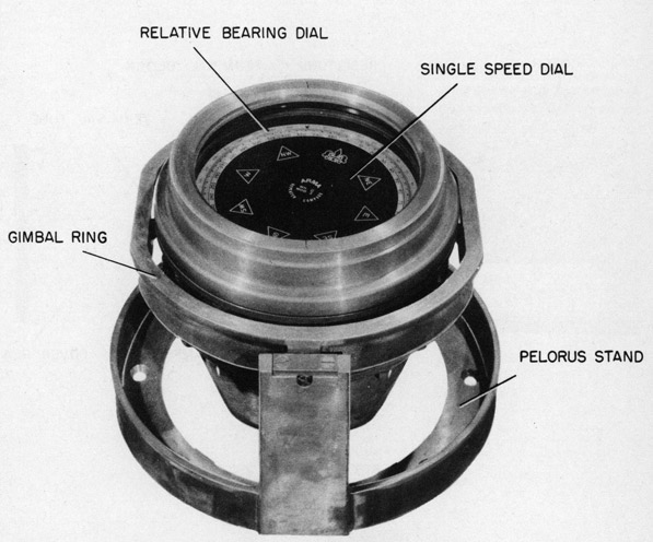
These receive and indicate the ship's heading. They may be mounted in bulkhead brackets or in gimbal rings for taking bearings.
6. Motor Generator Set
This unit converts the ship's supply to a three-phase, variable-frequency supply for driving the gyros.
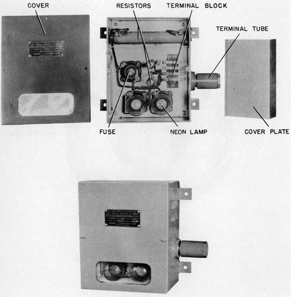
7. Alarm Flasher
Operation of the alarm flasher indicates failure of the master compass or ship's power supply.
8. Accessories and Tools
These are supplied for the adjustment or repair of the compass equipment.
16
MADE FROM
ARMA DWG. NO 57821
MASTER COMPASS
FIGURE 26
17
THE MASTER COMPASS
The master compass, shown in Figures 24 and 25, is the principal unit in the compass equipment. It consists of a mechanism or "sensitive element" which seeks the meridian, a support and housing for this element, and a means for indicating the ship's heading as determined by the sensitive element. The card at the top of the compass and a transmitter which controls the readings of all repeater compasses are not directly connected to the North-seeking element because that would interfere with the freedom of the element. Instead, a motor driven follow-up mechanism, electrically controlled by the position of the sensitive element through magnetic induction, follows the element whichever way it turns, carrying the transmitter brushes and card with it.
For convenience in describing it, the master compass may be divided into six major groups as follows:
1. Binnacle Stand and Gimbal Rings
As shown in Figure 26, the binnacle is a housing and support for the other compass units. Within its mid-section the binnacle supports, on ball bearings. fore and aft, an outer gimbal ring. Within this ring an inner ring is trunnioned on an athwartship axis.
2. Spider and Bowl
From the inner gimbal ring a large bowl is suspended by eighty uniformly spaced coil springs. One end of each spring is attached to the inner gimbal ring, and the other end is attached to a spring bracket which is fastened to the bowl. The purpose of this type of suspension is to hold the bowl central with respect to the gimbal rings, and provide proper cushioning for protection of the sensitive element. Motion of the bowl suspension is dampened by means of felt pads held against the bowl by sixteen flat springs attached to the inner gimbal ring. To the upper surface of the bowl is secured a spider, which, with the bowl, forms a frame for the compass mechanism.
3. Sensitive Element
This unit is the North-seeking part of the compass. Supported on a hollow sphere floating in a mercury tank, it occupies the enclosure formed by bowl and spider.
4. Mercury Flotation
The sensitive element of the compass floats in a spherical tank of mercury which is supported by the bottom of the bowl and rotated back and forth through a small angle by a mechanical oscillator.
5. Follow-up Mechanism
The follow-up mechanism consists of the follow-up coil, the follow-up motor which drives the follow-up coil, the compass cards, and the transmitter brushes. The coil is hung from ball bearings in the spider with its axis in the axis of rotation of the sensitive element. Carried on the sensitive element are two electromagnets which induce voltages in the follow-up coil. These voltages, suitably amplified, actuate the follow-up motor which, through gearing, drives the follow-up coil and maintains the position of the coil fixed relative to the sensitive element. In this way the card and repeaters are made to indicate the ship's heading as determined by the sensitive element.
6. Speed Correction Mechanism
The speed (course and latitude) correction is introduced by a mechanism between the follow-up coil and the transmitter brushes.
18
ARMA DWG. NO.57824
SENSITIVE ELEMENT
FIGURE 27
19
BINNACLE STAND AND GIMBAL RINGS
The binnacle stand, which supports and encloses the whole master compass, is made in two sections. See Figures 24 and 26. The upper section is in the shape of a truncated cone; the lower section resembles an inverted bell. Both the upper and lower sections of the binnacle stand may be split vertically for the purpose of passing through small hatchways. The small diameter of the lower section has a flanged ring which is bolted to the binnacle base.
Slots in the flanged ring around its clamping bolts permit the compass to be rotated through a small angle relative to the binnacle base which is rigidly fastened to the ship. This provision is made to facilitate exact alignment of the compass fore and aft.
The gimbal rings are mounted at the large end of the binnacle body. Inside the lower section, near its bottom, are fastened three terminal blocks for making connection with the control panel. Openings, covered by circular metal ventilator plates, are provided for access to the blocks, and for ventilation of the compass.
The binnacle top section is a cover attached to the lower section by latches. Its upper surface consists of a shatter-proof glass through which the compass card may be read. Near the port and starboard sides of the cover are two hinged doors for gaining access to the speed correction knob (Figure 34) and other parts. These doors are provided with hasps and padlocks.
To provide a relatively stable support for the compass, the frame consisting of bowl and spider is supported on gimbal rings within the binnacle stand. The outer ring is trunnioned fore and aft, in the binnacle. on ball bearings mounted in bushings. These bushings are made of phenolic insulating material to insulate the rings from the binnacle. Both the outer and the inner gimbal rings are so constructed that they can be separated into two sections, thereby allowing easy passage through small hatchways.
SPIDER AND BOWL
The compass frame, Figure 26, consists of a large bowl suspended from the inner gimbal ring by eighty soft coil springs, and a spider attached to the upper surface of the bowl. The spider and bowl are shown in Figures 94 and 106. The springs, which are uniformly spaced around the outer periphery of the bowl, hold the compass frame in the center of the space within the gimbal rings. This type of suspension was developed to provide protection for the sensitive element against shocks of high magnitude. Sixteen felt-tipped flat springs are fastened to the inner gimbal ring in order to damp the motion of the bowl. They are arranged so that the felts bear against the bowl with a slight pressure. The motion of the bowl across the felts results in a retarding effect which prevents prolonged bouncing of the suspended system following a violent disturbance.
The felt damps also act to suppress gimbal oscillations, for when the gimbals are tilted, the sidewise component of the bowl weight causes the bowl to move laterally in the plane of the tilt. The rubbing of the felts over the bowl removes energy from the system, and soon damps out any oscillations of the gimbals.
The enclosure formed by the bowl on the bottom is completed on top by the spider which is fitted with four removable transparent covers. The spider provides a space for the speed-course correction mechanism and supports the transmitter assembly, follow-up motor and follow-up coil. To the top of the spider is fastened the Follow-up Motor and Transmitter Support Casting which in turn carries the Driving Arm Support. These parts are shown assembled in Figures 25 and 39.
SENSITIVE ELEMENT
• General
The North-seeking portion of the master compass is the Sensitive Element shown in Figure 27. This unit through gyroscopic action and by virtue of the earth's rotation tends to keep its axis in the meridian. By means of the follow-up system and transmitter, the position of the element controls the reading of repeater compasses throughout the ship. Since the element must be extremely free to turn about any axis, it is supported by a steel ball which floats in mercury. Figure 33 shows the element in its proper relation to the other compass parts. In this view the spider has been removed so that the element may be seen.
20
21
The sensitive element consists of a frame on which are mounted two gyro units and an oil damping device. Each gyro unit is free to rotate about a vertical axis but the two units are coupled together by a linkage. On the element are two magnets for exciting the follow-up system, and an emergency azimuth scale which may be used in case the follow-up system should fail.
• Gyro Units
Two gyro units provide directive force for the sensitive element, that is, they turn it toward the meridian. One of these units, which are alike, is shown in Figures 28 and 29.
The casing of each unit is equipped externally with upper and lower spindles and ball bearings so that it is free to rotate about a vertical axis. These spindles (Figure 28) are furnished with the gyro unit, but the bearings are a part of the sensitive element frame. The lower spindle rests on a single steel ball which carries the gyro unit weight. Near the top of the casing and cover are circular plates which cover holes used in balancing the gyro rotor. Under these plates, around the sight glasses, and at other joints, neoprene gaskets are used to make the case air-tight.
The gyro wheel and its axle are machined in one piece from alloy steel. Each end of the axle is accurately fitted with ball bearings which are supported inside the gas-tight casing. The gyro wheel bearings are the finest obtainable, but the requirements are so exacting that each bearing is measured and selected for concentricity. No bearing is used which is eccentric by so much as one ten-thousandth of an inch. One side of the gyro wheel is machined out around the axle to take the induction motor windings. The squirrel cage is pressed into the gyro wheel. The primary, or stator, projects into the center of the rotor squirrel cage. Leads from the stator are carried thru the casing to terminals on the outside for connection to the supply line. Four axial tapped holes at 90° intervals around the rim of the wheel are each fitted with two threaded balancing plugs. At the factory these plugs are adjusted in position and weight to obtain static and dynamic (running) balance of the wheels. This is important because the wheels rotate up to 18,000 revolutions per minute and must be free from excessive vibration. Around the periphery of the wheel, a spiral groove is turned. This groove may be observed through a sight glass on the case to determine whether or not the wheel is rotating in the correct direction when it is started. The groove may also be used in connection with a stroboscopic device for accurate determination of the wheel speed.
The lubrication system consists of an oil sump at the bottom of the casing from which cotton wicks carry the oil up and around each of the axle ball bearings. The oil sump is provided with a drain plug and with a circular sight glass to show the oil level, the correct level being approximately at the mid-point of the glass. A high grade oil free from moisture and other volatile substances is used.
A vacuum is maintained within the case to eliminate windage losses, to reduce the heating of the rotor and to prevent gumming of oil in the bearings. A gauge on the unit shows the degree of vacuum and so serves to indicate possible leakage. The casing balance hole cover is fitted with an exhausting valve which is used in evacuating the case. On the North gyro unit, the positions of the vacuum gauge and sight glass are opposite to what they are on the South gyro. Therefore the units are not interchangeable until these parts have been interchanged.
• Gyro Coupling Linkage
When the two gyro units are in their normal positions on the sensitive element, the axes of the gyro wheels make 35° angles with the North-South axis of the element. Each gyro is pivoted on a vertical axis and the two are connected together by links in such a manner that they can turn thru equal and opposite angles only. Figure 27 shows the North gyro coupled by a link to a bell crank lever arm pivoted on the sensitive element frame. The South gyro is coupled by another link to the other end of the bell crank lever arm. On the side of the gyro units opposite the links, light coil springs hold the units centered in their normal position. See Figure 33. Neoprene cushioned stop screws on the sensitive element frame and a stop collar on the gyro coupling shaft limit the rotation of the gyro units.
The reason for having the gyros inclined and coupled by a linkage is to eliminate the intercardinal error by preventing the sensitive element from swinging in an East-West direction. When the frame tends to swing, the gyro units precess around their vertical axes in equal and opposite angles. As the ship rolls, the swinging tendency is first in one direction and then in the other
22
ARMA DWG. NO. 52399
EXPLODED VIEW OF
GYRO UNIT
FIGURE 29
23
causing the gyros to turn back and forth through a small angle. Since this does not turn the sensitive element as a whole, the compass reading is not affected.
• Oil Damping System
On the East side of the sensitive element frame, Figure 27, are two tanks partly filled with oil and connected at their bottoms by a pipe. Were it not for this damping system, the element would continually oscillate back and forth across the meridian instead of settling down in its correct position. Figure 30 shows the two tanks in a sectional view. They are aligned parallel to the meridian, and are totally enclosed. The tanks are connected by a pipe line at the bottom for oil, and by another at the top for air. They are filled to a depth of 1-1/4".
In order to obtain the proper damping percentage, it is necessary to restrict the flow of oil between the tanks. This is accomplished by means of an obstruction inserted in the pipe line.
To avoid the damping error, as explained on page 11, it is necessary to nullify the effect of
OIL DAMPING SYSTEM
FIGURE 30
the damping system during changes in course. To prevent flow of oil due to the accelerating forces present during a turn, a damping cut-cut valve is placed in the oil line connecting the two damping tanks. This valve operates whenever the change in ship's course is greater than 15° and is controlled automatically by a pair of contacts in the transmitter assembly, Figure 40. The valve consists of a steel ball, inside of the oil line, which can be drawn up vertically against a spherical seat by an external electromagnet when the oil flow is to be stopped. Thus the valve is operated without disturbing the equilibrium of the sensitive element in any way.
• Follow-up Magnets
Two A.C. magnets are carried on the frame of the sensitive element for exciting the follow-up system. These are located at opposite extremities of the East-West axis of the element in such a way that their fields are cut by the adjacent follow-up windings.
• Mercury Contact Parts
Four electrical connections are made with the sensitive element. One is made through the mercury bowl, and the other three through a contact pin, a bell-shaped spinning, and a wire ring dipping into three concentric mercury cups, insulated from each other, at the center of the float ball. See Figure 31. These contacts are suspended from a tubular rod which extends vertically downward from the center of the follow-up coil support. They therefore remain in the same relative position with respect to the sensitive element except for the very small angle of lag in the follow-up system. The center contact pin also acts as a lateral guide to hold the sensitive element to the central position
24
FLOTATION and CONTACT ASSEMBLY
FIGURE 31
25
in the flotation bowl. The support tube is held vertical by a spring which allows a slight lateral movement of the element for protection of the retaining pin. The damping cut-out magnet, follow-up magnets and transformer, and the gyro units on the sensitive element receive power through the above described contacts.
• Emergency Azimuth Scale, Levels and Weights
An emergency azimuth scale is carried on the top of the sensitive element. It may be read by removing the binnacle cover and sighting the scale across two parallel lines conveniently placed on one of the upper spider covers.
The sensitive element carries two spirit levels accurately aligned with respect to the gyro axes. The levels are placed at right angles to each other. The North-South level, mounted on the East side of the element, is graduated from 40 to 60 minutes, in one-minute divisions, because the reading of this level is of importance in telling when the element has settled on the meridian. The East-West level has a central position etched on the level tube. A few compasses have graduated levels.
Three adjustable weights are provided on the element for making the horizontal balances: a North-South level weight, an East-West level weight, and a latitude leveling device, shown on Figure 27. The first two weights are used to bring the element to a level position when settling on the meridian. The purpose of the latitude leveling device is to reduce the North-South tilt of the sensitive element, and thereby reduce the error caused by changes in the gyro wheel speed when the element is tilted. A weight, adjustable in a vertical direction, is provided for fine adjustment of the pendulous factor. There is also a weight on the gyro coupling lever to keep the element balanced for all positions of the gyro units.
NOTE: Make no adjustment of any nature, with the exception of the latitude leveling device, before thoroughly reading the section on adjustments, page 101. Instructions for adjusting the latitude leveling device are found on page 84, Item (9).
In addition to the adjustable weights, there are permanent weights mounted on various parts of the element and gyro cases. Between the sensitive element frame and its supporting member are washers, Figure 31, put in place at the factory to adjust the pendulous factor. Under no circumstances should these washers or the permanent weights be disturbed. The thickness of the pendulous factor washers, in inches, .is stamped on the upper surface of the sensitive element frame.
MERCURY FLOTATION
• Flotation
The directive force of any gyro compass is small when nearly on the meridian. It is therefore necessary to suspend it in as nearly a frictionless support as is possible. This is accomplished by supporting the sensitive element on a hollow steel sphere which floats in a concentric tank of mercury; see Figure 31. The element is constrained from drifting laterally by the center electrical contact pin which fits loosely into a guide at the center of the floating sphere. This pin, together with a pair of concentric contact rings, projects from a shaft which is carried at the center of rotation of the follow-up arms. Thus there is practically no relative rotation between the contact pin and rings and the sensitive element. The inner of the two contact rings is actually an inverted cup, and is designed to prevent vibration from causing the transfer of mercury from the outer collector cup to the inner one. The vertical position of the element is governed by the quantity of mercury in the tank. The sphere should clear the bottom of the tank by 3/16". For convenience in checking this position, a line has been placed on the contact support tube. This line is level with the topmost surface of the sensitive element when the flotation is correct.
Electrical connection to the contact pin and rings is made by wires which pass up through the contact support tube as shown in Figure 31 to brushes which bear on slip rings on the lower side of the spider casting.
The upper part of the mercury tank is shaped to conform to the upper part of the float ball by means of a collar, which forms a continuation of the spherical part of the tank. The collar is fitted with slots and a damping chamber to suppress splashing and wave motion of the mercury. The collar is fitted with four spring clips which hold it in place. When the sensitive element is lifted out for inspection, the collar is lifted with the element. When the element is lowered into the float tank the collar will rest on the rim of the mercury tank supported by the spring clips. The collar must be seated slowly to prevent spillage of mercury.
Figure 33 snows how the sensitive element and flotation assembly are supported in relation to the gimbal rings and other compass units.
26
• Oscillator Mechanism
To eliminate any possible static friction in the mercury which would slightly reduce the freedom of the sensitive element, the tank is suspended from leaf springs and caused to oscillate continuously through a small angle several times a second. The oscillator mechanism is located below the tank as shown in Figure 32. The mechanism consists of a split-phase induction motor driving an eccentric and connecting linkage.
The motor, which is the induction type having a laminated rotor and a four pole stator, occupies the circular space within the supporting sleeve for the tank. It is geared to a small eccentric carrying an eccentric sliding block. A guide member engages with this block and transmits the oscillating motion to a pair of spiders pinned to the lower part of the supporting sleeve. The complete mechanism below the motor windings is submerged in oil to insure quiet and dependable operation. One plug serves for filling and for overflow.
FOLLOW-UP MECHANISM
• General
The follow-up mechanism is that part of the master compass which drives the card dials and controls the repeater compass readings without reacting upon the sensitive element. This is accomplished by amplifying a small voltage which is induced in the follow-up coils by magnets on the sensitive element, and using the amplified voltage to control a motor geared to the card and follow-up coil. The motor operates to keep the follow-up coil and the card in their proper position relative to the sensitive element. The follow-up mechanism is part of the master compass. It is to be distinguished from the follow-up system which includes the mechanism and the follow-up panel.
The follow-up mechanism is made up of the following units:
1. Follow-up Coil
2. Follow-up Motor
3. Compass Card
4. Commutator Transmitter
5. Driving Mechanism, consisting of gearing and shafts which connect the motor, cards, and coil
6. Speed Correction Mechanism
7. Damping Cut-Out Contacts
• Follow-up Coil
The follow-up coil consists of a winding and a circular frame made of phenolic insulating material. See Figure 34. The coil is suspended from the spider by the follow-up coil support. The winding is connected through slip rings on the spider to the follow-up panel. Since the coil is fixed in relation to the sensitive element, it turns relative to the ship and spider.
• Follow-up Motor
The follow-up coil is driven by a two-pole direct current motor whose armature current is supplied by the follow-up panel. When the follow-up coil is displaced from its neutral position with respect to the sensitive element, current flows through the motor in a direction which causes it to drive the coil back to its correct position. The motor, which is mounted on the spider, Figure 34, also drives the transmitter brushes and card.
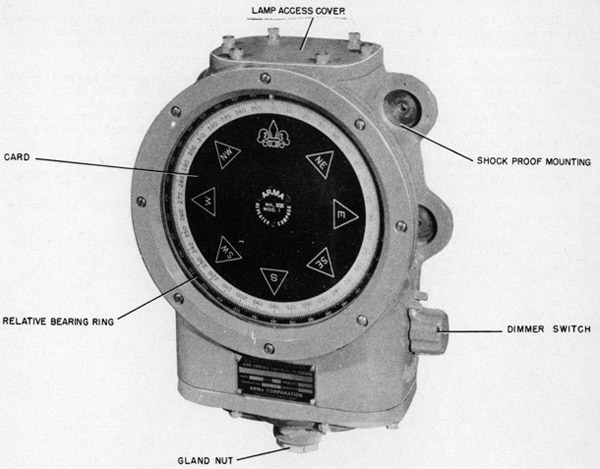
• Compass Card
The compass card on top of the spider assembly, Figure 34, is clearly visible just below the glass cover of the binnacle. Bearings can be read in tenths and hundredths of a degree. This is made possible by two concentric dials having a 36 to 1 displacement ratio. The entire circumference of the outer dial is divided into ten major divisions to indicate ten degrees of arc so that each major division corresponds to one degree. Each major division is subdivided into tenths, and each tenth is large enough to estimate hundredths. Actual bearings are read against the lubber line fixed on the head. The inner dial carries 36 divisions, each of which represents ten degrees of arc. When the ship makes a complete turn of 360°, the inner dial makes one revolution while the outer dial
27
OSCILLATOR ASSEMBLY
FIGURE 32
28
MASTER COMPASS DIALS
29
ARMA DWG. NO. 57820
MASTER COMPASS
SPIDER REMOVED SHOWING
SENSITIVE ELEMENT IN PLACE
FIGURE 33
30
ARMA DWG. NOS. 50341, 50560 and 52768
SPIDER ASSEMBLY
FIGURE 34
31
makes 36 revolutions, or one revolution for every 10° of arc. The speed ratio of the dials is therefore 36 to 1. See sketch on page 28.
• Commutator Transmitter
It is the purpose of the transmitter to convey the ship's heading to all repeater compasses. The commutator type transmitter is particularly suitable where a high degree of accuracy is required in operating a comparatively large number of repeaters. In the Arma Compass the transmitter is situated at the top of the spider assembly as shown in Figure 34. The principal units of the transmitter are a toroidal transformer, a commutator having 360 radial segments, two sets of transmitter brushes, and two sets of collector rings.
Figure 40 shows a section through the commutator and brush assembly. Near the inner end of the commutator segments rest three brushes, one of which is seen in the figure. The other two are spaced 120° from the first. These brushes, which turn with the 36-speed dial, pick up potentials from the segments energized by the transformer, and through the lower collector rings transmit the potentials to the repeater compasses. Near the outer ends of the segments rests a set of three brushes which, driven by a large gear, turn with the single - speed dial. Through the upper collector rings they transmit the single-speed dial bearing to the repeaters. In this way the positions of single and 36-speed dials are transmitted independently of each other to the repeater compasses.
• Driving Mechanism
The driving mechanism is a gear train through which the azimuth follow-up motor drives the follow-up coil, course dials, and transmitter brushes. See Figures 40 and 41.
Starting at the follow-up coil, and tracing the gearing back to the motor, the first part considered after the coil is its support, which is clamped to a stalk. By loosening the screws which clamp the support to the stalk, the follow-up coil may be adjusted relative to the gears and card. The stalk is supported on ball bearings in the spider frame. Pinned to its upper end is a gear A, which, with gears G, D, E, and fork F, are part of the speed correction mechanism. When there is no correction to be made, gear G, which supports idler pinion D, fork gear segment E, and fork F, turns as though directly connected to the stalk. A vertical pin, B, fastened to the hub of gear G is engaged with a slotted link pinned to the single-speed dial shaft. Therefore, the single-speed dial turns exactly with the follow-up coil when there is no speed correction. The use of the pin coupling arrangement simplifies the disassembly and reassembly of the compass head.
At the forward side of the large single-speed gear G, a pinion H drives a vertical shaft leading to the transmitter, where the shaft is geared to the single-speed brushes. On the same shaft is a large gear I which drives the 36-speed hollow shaft J, carrying the 36-speed transmitter brushes, and the 36-speed dial at its upper end. On the lower end of this shaft is a large gear K, which, through gears L, M, N, is connected to the follow-up motor.
When the follow-up motor turns it drives the 36-speed shaft, transmitter brushes, and card. Through gears, S, I, H, G, E, D, and A, it also drives the single-speed card and brushes, and the follow-up coil.
SPEED CORRECTION MECHANISM
In the chapter on THEORY, page 10, it was shown that when a ship is travelling on other than a true Easterly or Westerly course, the sensitive element does not settle on the true meridian. For this reason a correction is introduced into the system.
The automatic speed correction mechanism is provided with a synchro motor which receives an indication of ship's speed from the underwater log, and a follow-up motor applies this quantity to a lever-type multiplier. By means of a manual control, which is graduated in degrees of latitude, the secant of the latitude is introduced into the multiplier, and the resulting product is applied to an eccentric bearing in the correction mechanism. The speed corrector requires manual resetting only for changes in latitude; speed variations are taken care of automatically.
This mechanism is shown schematically in Figure 41. The synchro motor receives an indication of the ship's speed from the underwater log. The synchro input is linear over the entire range 0 to 25 knots, 14.4 degrees per knot. Mounted upon the shaft of, this synchro is a light brush which travels over the two segments of a follow-up head. This head is geared to a motor, and the segments are wired to the motor in such a manner that a displacement of the brush either way will start the motor driving the head in the same direction, so as to follow, exactly, the movements of the synchro motor.
32
The small torque of the synchro is thereby amplified sufficiently to operate the corrector mechanism. In order for the follow-up to synchronize in the correct direction when first turned on, it is necessary that the head be within one-half turn (about 12 knots) of the synchro motor position. The method of setting the head is described under OPERATION, on page 85.
By means of an accurate lead screw, this speed quantity is introduced into a slotted link, which transmits the motion to the eccentric bearing. The fulcrum point of this link is a pivot mounted on a slide capable of being moved at right angles to the direction of the eccentric travel. Movement of this pivot increases or decreases the effect of the speed input upon the eccentric bearing. This has the effect of multiplying the speed input by a varying quantity. The pivot is moved with another lead screw actuated by the latitude knob. This knob is graduated from 0 to 70 degrees in such a manner that the pivot location for any setting will multiply the speed input by the secant of the latitude. The resulting eccentric bearing movement is then proportional to the product of the ship's speed and the secant of the latitude. The position of the eccentric bearing should always satisfy the following equation:
Bearing Displacement = A Constant x Ship's Speed x Secant Latitude
A knob is provided for setting the speed input manually, when the automatic speed transmission is turned off. The manual speed correction introduced into the mechanism is shown on a counter. The setting of the synchro is read on a ring dial mounted over a pointer on the synchro shaft. These readings will match when the follow-up is functioning correctly.
Figure 35 shows the elements of the eccentric bearing mechanism in the position they occupy when the ship is headed North before any correction has been made. A gear A is pinned to the upper end of the follow-up coil support stalk. It meshes with idler pinion D which also meshes with gear E rigidly fastened to a fork F. The letters are the same as used in Figures 40 and 41. The sides of the fork rest on a large diameter ball bearing Q. When there is no correction this bearing is centered as shown in Figure 35. If the ship is travelling North, the sensitive element axis settles to the West of true North, and a correction is automatically introduced by the mechanism described previously. This correction causes rail R to move bearing Q Northward as shown in Figure 36. Fork F is rotated about its center P, and through idler pinion D turns gear A, so that the follow-up axis is turned through the correction angle, and its East-West axis is opposite the sensitive element magnets. The card reads the corrected North position, the sensitive element has settled in its new position, and the follow-up system is in equilibrium, because the coil axis is opposite the follow-up magnets.
33
If the ship changes its course to due West. the sliding rail R, and bearing Q, turning with the spider, occupy the positions shown in Figure 37. Being geared to the follow-up coil, the fork pivot remains in the West but the fork is rotated back to its original Position since the displacement of Q is now directly toward the fork axis P. The correction introduced by the mechanism has been reduced to zero which is as it should be because there is no speed error on a Westerly course. The action of the mechanism is such as to convert the correction for a Northerly course into the proper correction for any heading the ship may have.
Figure 39 shows the correction mechanism parts as seen when the upper section is removed from the spider. In Figure 40, which includes a section through the mechanism, it is seen that in operation the correction is made as an angular displacement between gears A and G. On account of this correction, the card and repeater compass indication will not agree with the emergency azimuth scale reading unless the speed correction is zero.
When the ship goes astern, the speed error is in the opposite sense to the error for forward motion. Since the mechanism is not built to apply negative corrections, the speed input should be set to zero when the ship travels astern for an appreciable period of time.
• Damping Cut-Out Contacts
In order to eliminate the damping error it is necessary to operate the damping cut-out valve (page 23) when the ship changes course. This is accomplished by a pair of silver contacts in the transmitter assembly. See Figure 40. Two contacts, electrically connected, are carried on a block which is clamped lightly around the middle collector ring on the single-speed brush assembly. The contact assembly is shown in Figure 40. A stationary contact pin between the other two limits their motion to a few degrees. As the ship changes course the brush assembly turns, carrying one of the moving contacts against the fixed contact. This operates the damping cut-out valve. Further rotation of the brush assembly causes the clamp springs to slip on the collector ring. When the turn is completed, normal yawing of the ship breaks the contact and damping is restored. Occasional operation of the valve as by excessive yaw does not disturb the compass.
FIGURE 38
34
SPEED CORRECTION MECHANISM
FIGURE 39
35
Page 35 oversize drawing.
Automatic Speed Correction and Driving Mechanism
Complete with Transmitter Commutator and Card Assembly
Figure 40
36
Page is blank.
37
38
Page is blank
39
DECK-MOUNTED TYPE
MK. I MOD. 2 ARMA DWG.50460
MOTOR GENERATORS
FIGURE 42
40
MOTOR GENERATOR
• Function
The motor generator set converts the ship's direct current power supply to a three-phase supply of variable frequency for driving the gyro wheels.
• Construction
Both deck-mounted and ceiling-mounted motor generators are supplied; see Figure 42. The ceiling-mounted type is the same as the deck-mounted, except that the drip-proof slots are reversed, and elbow fittings are added to the grease cups to make them accessible. The same parts are used in both types, the method of assembly being slightly different. A deck-mounted spare can be used to replace a defective overhead-mounted generator by changing it as follows:
1. Reverse resistor cover, in order to make drip-proof slots open downward.
2. Remove grease cups, and invert end bells for same reason. Be careful not to disturb brush setting on commutator end.
3. Remove elbow grease fittings from ceiling-mounted generator which is being replaced, and install them in the spare generator.
If a ceiling-mounted spare is used to replace a deck-mounted unit, the grease elbow fittings must, of course, be removed, and the grease cups screwed directly into the end bells.
The motor and generator are enclosed in one drip-proof housing, Figure 42. Their rotors are on one shaft which is supported at the frame ends on ball bearings, each bearing being lubricated by a grease cup. Removable plugs at both ends, fastened to the frame by a chain, permit speed readings to be taken without removing the entire end plate. The generator is driven by a compound-wound, direct current motor, rated at 120 volts, 3 amperes, and 3000 R.P.M. Speed control is obtained by means of an external rheostat, Figures 44 and 55, in the field circuit. The motor has been specially designed for good speed regulation so that the effect of variations of the supply voltage on the motor speed has been reduced to a minimum. A fixed resistor on the frame is adjusted by the manufacturer to compensate for electrical differences between generators.
The three-phase generator which drives the gyro wheels is rated at 67.5 volts, 2.0 amperes, 300 cycles at 3000 R.P.M. When the motor speed is reduced, the generator voltage and frequency are correspondingly reduced. Direct current required to excite the generator field is obtained through the control panel from the ship's supply.
41
ARMA DWG.NO. 57916
CONTROL PANEL
(UNIVERSAL PORTSMOUTH TYPE)
FRONT VIEW FIGURE 43
42
CONTROL PANEL
UNIVERSAL PORTSMOUTH TYPE
REAR VIEW
FIGURE 44
43
CONTROL PANEL
• General
Figure 43 shows the repeater, control and follow-up panels. The control panel, as its name implies, is used for controlling operation of the master compass, and for indicating conditions of operation such as current and voltage values. The panels are made of gray insulating material and are supported on a welded steel frame.
Power is carried to the panel from the ship's supply by a 115-volt direct current line, and a 115-volt, 60-cycle, single-phase A.C. line. A motor generator set powered from the direct current line provides a variable-frequency three-phase supply for driving the gyro wheels. Connections to motor generators, master compass, and other equipment are made through the control panel.
• Instruments
At the top of the control panel are two ammeters, two voltmeters, and a neon indicator lamp. The lamp serves as an indicator for the damping cut-out; it operates when the oil flow between the damping tanks has been cut off. The four instruments indicate: (1) the gyro drive current in each phase; (2) the current drawn by the repeater system; (3) the D.C. supply voltage; and (4) the gyro variable frequency supply voltage, and the 60-cycle, single-phase A.C. supply voltage.
• Switches
On the left side of the panel is an ammeter switch marked "Gyro Current" for connecting the instrument above it to measure the gyro motor current. Three positions marked "1", "2", "3" are provided for the three phases.
To the right of the gyro current switch is an alarm selector switch with five positions: "Normal", "Off", "Test 1 Gyro Supp.", "Test 2 A.C. Supp.", and "Test 3 F.U. Amp.". This switch is ordinarily left at "Normal". Should the alarm bell operate, indicating trouble in the line voltage or compass follow-up system, the exact location of the difficulty may be found by turning the switch to the various "Test" positions. The alarm will cease flashing when the trouble position is reached. If, at any time, it is desired to test the proper functioning of the alarm relays, the switch can be turned to successive "Test" positions. The alarm flasher should operate on all three "Test" settings.
In the center is a damping cut-out switch which has three positions: "On", "Auto", and "Off" When the switch is in the "On" position continuous damping is obtained. When on "Auto", the damping cut-out valve is open except when the damping cut-out contacts on the transmitter head close during a turn. This is the normal running position. In the "Off" position the switch closes the valve, cutting out the damping, The "Off" position is used when ordered by the Navigator during large speed changes to avoid the damping error. This is a rotary snap switch having a special feature in that to make the switch stay in the "Off" position it is necessary to press the handle firmly toward the panel. The parts of this and all other switches are illustrated in Figure 110.
The second switch from the right has three positions, respectively: "Off", "Azim. Only", and "Speed Corr. & Azim." When in the center position, the automatic speed corrector is disconnected, and the mechanism may be operated manually. The azimuth follow-up, however, will continue to function.
At the right hand end of the row of switches is a switch for connecting the A.C. voltmeter across the gyro three-phase line or the 60-cycle, single-phase line.
Below this row of switches is a second row of two switches. At the left hand side of this row is a motor generator switch controlling the motor power supply. Since there are two motor generators for each compass, two sets of "On" positions are provided in order that either motor generator may be used. The motor generators are designed to start directly across the line, hence no starting positions are necessary.
Opposite the motor generator control switch is a switch for turning on the A.C. and D.C. supply. The first position turns on the A.C. only, so that the follow-up panel tube filaments may be heated before the plate potential is applied to the grid control rectifier tubes by turning the switch to the second position "ON".
• Fuses
Below the two rows of switches are indicating fuses for the protection of the various circuits. Safeguarding of the operator against shock by accidental contact with the fuses has been accomplished by covering the fuses with a guard. An opening is provided in the guard for inspection of the fuses and a nameplate on the guard shows in which circuits the fuses are connected. A blown fuse is readily
44
CONTROL PANEL
identified by the lighting of a neon indicator, which shows through the opening in the guard. Fuse current capacities, indicated on the panel under each fuse, are as follows:
D.C. Supply for Motor Generators
20 amperes
Gyro. Supply
10 amperes
Transmitter High and Low Speed
4 amperes (time lag)
Transmitter A.C. Supply
10 amperes
A.C. Supply for Follow-up System
6 amperes
Speed Corrector
1 ampere
Follow-up Motor Armature
3 amperes
Follow-up Motor Field
1 ampere
• Time Lag Fuses
On the front of the control panel are six time-lag fuses of 4 ampere rating, one for each of the transmitter secondary leads.
They are designed to withstand the initial load created momentarily when the repeaters are first switched on. This surge of current is sometimes considerably higher than normal, until the repeaters are synchronized, and, although of very short duration, would blow out an ordinary fuse of the proper rating for the normal circuit load. The time-lag fuses will blow under the action of a prolonged overload large enough to damage the transmitter.
ARMA DWG. NO. 53742
CONTROL PANEL
HINGED DOORS OPEN
REAR VIEW
FIGURE 45
45
• Ballistic Adjustment Rheostat
As explained on page 11, it is necessary to have the gyro wheel speed proportional to the cosine of ship's latitude in order to avoid a temporary ballistic deflection error on change of speed or course. The correct gyro wheel speed is obtained by turning a graduated dial until it indicates the ship's latitude. This dial, which is marked "Latitude" and is located between the motor generator and the A.C. and D.C. supply switches (see Figure 43), is directly connected to a rheostat in the motor field circuit of the motor generator. Since the gyro wheel speed is determined by the frequency of the generator, the latitude dial is calibrated to give the correct wheel speed for each latitude setting.
The gyro wheel speed is held within close limits because of the good speed regulation of the motor generator; a 5% variation in the supply voltage resulting in only a 2-1/2% change in frequency and the gyro wheel speed.
The knob on the latitude dial has a special feature in that to change the setting of the dial it is necessary to press the knob toward the panel and to rotate it until the dial is engaged. This type of knob is used in order that the setting of the dial cannot be affected by accidental contact.
• Relays
On the rear of the control panel, Figure 44, on a hinged sub-panel are two low-voltage relays and a damping cut-out relay.
One of the two low-voltage relays is connected across the 60-cycle line; the other is across one phase of the gyro supply. Both relays in their released positions close a 115-volt 60-cycle alarm circuit which operates a flasher. These relays operate on the same principle. Each has a contact arm which is normally held in the open position as long as the voltage is above its minimum permissible value. When the voltage drops below this value, the windings of the relay no longer hold the arm open and the alarm circuit is completed.
The damping cut-out relay consists entirely of electrical circuits with no moving parts. It is connected in series with the damping cut-out transformer and lights a neon lamp on the front of the panel when the damping is inoperative. The damping cut-out relay is similar in appearance to the synchro overload relay which is shown in Figure 46.
• Other Parts
On the rear of the control panel and on the hinged sub-panels are also mounted two transformers, a rectifier, a reactor unit, and resistors which are included in the electrical circuits described on page 56 and pages following.
SYNCHRO OVERLOAD RELAY
FIGURE 46
46
REPEATER PANELS
• General
The two repeater panel sections are mounted directly above and on the same frame with the control panel. See Figure 43. On these panels are switches, fuses, and lamps for controlling and protecting the repeater compass circuits.
• Switches
The rotary repeater switches control the repeater compasses and other instruments requiring a course indication. All switches have four positions which are engraved on the rotary nameplate. There are two repeaters connected to each switch, and the four positions permit them to be turned on separately or together.
• Fuses
Above the repeater switches is a row of 3-ampere capacity fuses, divided into groups of two, each group being connected in one repeater field circuit. All fuses are fitted with neon indicators, which light when the fuse is blown. The fuses are covered by a guard to protect the operator from shock by accidental contact. There is an opening in the guard to permit inspection of the neon indicators, and a nameplate is fastened to the guard indicating the circuit name and symbol, the normal load, and the proper fuse size.
• Relays and Trouble Indicating Lamps
Repeater circuits are connected through overload relays, which light associated indicator lamps when the repeater current is excessive. This will occur, for example, when a repeater synchro motor is restrained from turning. The relay, shown in Figure 46, is mounted on the rear of the panel, and consists entirely of electrical circuits; it has no moving parts. When the repeater current exceeds a certain value, current passing through the relay lights a neon lamp. See page 68 for the circuit description of the overload relay.
47
FOLLOW-UP PANEL
• General
Below the control panel, Figure 43, is mounted the follow-up panel which carries electrical units required in the operation of the follow-up system. Front and rear views of this panel are shown in Figures 47 and 48. The tube box houses the two rectifier tubes which are mounted on a rubber cushioned tube shelf. This design gives protection to the tubes when shocks of high magnitude are encountered. Direct current for the amplifier tube is obtained from a rectifier in the amplifier unit. A voltage induced in the follow-up coil by magnets on the sensitive element is amplified by a type 6A6 tube, Figure 47. The amplifier is shown in Figures 48 and 56. The amplified voltage is applied to two grid control rectifier tubes. These tubes are so connected that the plate current of one runs the follow-up motor in one direction while the plate current of the other runs the follow-up motor in the opposite direction. When the follow-up coil is displaced from its normal position, current flows through one of these tubes and through the follow-up motor armature in such a direction as to turn the coil back to its correct position. When the coil is at rest some current flows in each tube. On the rear of the panel next to the amplifier unit, Figure 48, is the "anti-hunt" unit which prevents excessive oscillation, or hunting, of the follow-up mechanism.
Operation of the type 6A6 amplifier tube may be checked by the plate current milliammeter located on the front of the panel, above and to the left of the amplifier tube. Directly above the tube
ARMA DWG. NO. 53710
FOLLOW-UP PANEL MK. 7 MOD.4
FRONT VIEW
TUBE BOX COVER REMOVED
FIGURE 47
48
FOLLOW-UP PANEL
is a control for adjusting the sensitivity of the follow-up system. A low sensitivity results in a small lag in the follow-up during rapid course changes caused by yawing of the ship. If the sensitivity control is advanced too far, there is an unnecessary load on the system and the follow-up becomes responsive to small vibrations resulting in roughness of operation. Ordinarily a setting of the sensitivity control about three-fourths of the total setting is found satisfactory.
The operation of the grid control rectifier tubes is indicated by a meter between the two tubes. The purpose of the meter is to indicate, in case of tube failure, which tube should be conducting. Under operating conditions, yawing of the ship may cause the needle to swing from side to side.
To the right of the anti-hunt unit is a sensitive relay which releases when the follow-up coil does not properly follow the sensitive element. This relay in its released position operates the same alarm flasher as the low-voltage relays.
Due to the sensitive nature of this relay, alarm operation may be observed when the panel is subjected to shock, such as firing practice. The alarm switch may be turned to the "OFF" position during these conditions, or the operation of the alarm may be ignored, as the indication will cease when the shock stops.
Several types of repeater compasses are used for indicating the ship's heading which is determined by the master compass and conveyed electrically from the commutator transmitter to the repeaters. Figure 49 illustrates a repeater in a bulkhead mounting bracket which permits tilting the repeater up and down or turning it from side to side and clamping it in any position.
• Synchro Motor
In its simplest form the repeater consists of a compass card fixed to the end of the shaft of a synchro motor whose rotor turns in synchronism with the master compass transmitter brushes.
One type of synchro motor is used in all repeaters of the Mark 7 Mod. 4 Compass Equipment. It is shown, with all its parts, in Figure 133. The synchro motor, type 5F, has a two-pole laminated field structure, which turns within a stator having a three-phase winding. The rotor turns in ball bearings and is equipped with silver collector rings. Brushes having silver contacts make connection with the collector rings.
A damping device is mounted on the rotor shaft, so that it may turn with slight friction. Slow movements of the rotor turn the damp with it, while a quick movement causes slipping of the friction device, which reduces the tendency of the rotor to overshoot its resting position after a rapid change in heading.
• Single Dial Bearing Repeater Mark 3 Mod. 11
The Mark 3 Mod. 11 repeater, Figure 49, includes a single large dial turned by one synchro motor. This repeater is used at stations where one-degree dial divisions give sufficiently accurate readings. The dial of this repeater has an outer rim of a translucent material which is yellow on top and red underneath, with graduations and numbers filled black. At night, when the dial is illuminated from below by the two 130-volt lamps, the translucent rim appears red. A frictional damping device on the dial reduces undesirable oscillations. Around the bearing dial, the repeater has, fixed to its case, a ring dial graduated from 0° to 360° in one-degree divisions. This relative bearing dial is used in determining the bearing of an object relative to the ship.
The bezel ring of this repeater has a diameter of 9.697 inches, to permit the use of a Navy standard azimuth circle or bearing circle.
50
• Double Dial Concentric Steering Repeater Mark 6 Mod. 0
The Mark 6 Mod. 0 repeater has two concentric dials as shown in Figure 50. The inner dial, which resembles that on a single dial repeater, is driven through gearing by a synchro connected to the 1-speed transmission. The outer dial is driven from the 36-speed transmission through a 6 to 1 gear reduction. It makes six revolutions to one of the inner dial, and permits readings to 0.10 degree. So that the more rapid movement of the outer dial will not distract the eye from the inner 1-speed dial a mask is provided which covers all but 5 divisions of the outer dial.
The dials of this repeater are made of three-ply material, the middle ply being a red translucent substance. The markings are engraved through an outer opaque layer into the red material, and filled with translucent white. The engravings appear red when illuminated from below, but white in daylight. Four 130-volt lamps are provided for illumination.
Electrical connections to the repeaters are made through a rubber covered cable passing through a stuffing gland at the bottom of the repeater casing.
• Connection Boxes
With each repeater that is mounted in a bulkhead bracket, there is a connection box as shown in Figures 49 and 50. The connection box is patterned after the Bureau of Navigation Standard Connection Box. The connection box cover is fastened to the repeater cable, the wires of which are connected to plugs which fit into receptacles in the connection box. These receptacles are in turn connected to the ship's cables. In the switch cover is a rheostat for controlling the repeater lights and a 1-ampere fuse for protecting the light circuit. The two covers are fitted with gaskets to make the box watertight and both covers are fastened to the base by four bolts. The base is a part of the bulkhead bracket and the same box maybe used for two and four lamp repeaters.
• Single Dial Bulkhead Mounted Repeater Mark 0 Mod. 1
This repeater, shown in Figure 51, does not require a mounting bracket. It is designed to mount directly on the bulkhead. The four mounting lugs are provided with shock-proof inserts which effectively prevent shock from being transmitted to the repeater mechanism. Connections to the repeater are made within its own case, and the dimmer switch is an integral part of the unit, thus eliminating the need for an external dimmer switch and connection box. Contributing to the compactness of this repeater, is the bevel gear transmission from the synchro to the dial. This arrangement permits mounting the synchro with its axis at right angles to the dial. Around the single rotating dial, which is similar to those on the Mark 8 repeaters, the bulkhead repeater has a stationary relative bearing dial of opaque material with red markings.
52
• Double Dial Bearing Repeater Mark 2 Mod. 3
The double dial bearing repeater, Figure 52, is used where more accurate bearings are necessary than can be obtained from the single dial bearing repeater. In this repeater there are two concentric dials driven by synchros connected to the 1 and 36-speed brushes, instead of one dial driven by a synchro connected to the single speed brushes, as in the single dial repeater.
The outer moving dial is a ring of a translucent material which is yellow on the top surface and red on the bottom. The graduations are engraved and filled black. The dial is driven thru a 36 to 1 reduction gear from a synchro motor connected to the 36-speed transmitter brushes; hence it turns in synchronism with the single-speed compass dial. Transmission errors are reduced by this construction to 1/36 of their value in the single dial repeater. Inside the ring is another dial driven by a synchro connected to the single-speed brushes.
The inner dial has an outer rim of yellow and red translucent material on which the numbers are engraved and filled black. Markings designating the cardinal and intercardinal points are engraved on the black sheet metal inner portion of this dial and filled yellow.
Outside the outer moving dial, there is a relative bearing dial of the same translucent material This dial is used when taking bearings of objects relative to the ship.
The translucent portions of the dials are illuminated from behind by four 130-volt lamps, and appear red at night.
The repeater is housed in a bronze pressure-proof casing.
The Mark 1 Mod. 0 alarm flasher unit indicates a failure of the ship's power supply, by alternately flashing the two neon lights visible through the window in its cover. The unit consists of the before mentioned neon lights, a "twinkle" type flasher button, held in a socket by a plug type fuse, and four external resistors. The appearance of the units is shown in Figure 53 below. For circuit description, see page 70.


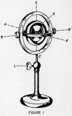 If a heavy wheel is mounted so that its shaft is free to turn in any direction, it is known as a free gyroscope. Usually the mount is constructed with three mutually perpendicular axes about which the wheel may turn. Thus in Figure 1 the wheel, G, is free to spin about axis A-A', to turn about horizontal axis B-B' and finally to turn about vertical axis C-C'. The gyro wheel is located so that its center of mass coincides with the intersection of these three axes.
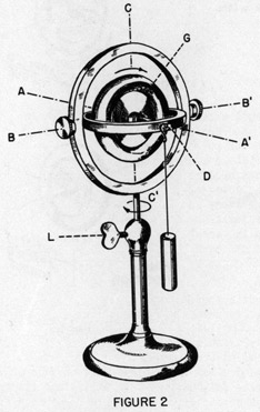 It should be noted that a pressure applied to the gyro wheel frame always results in reaction forces at the bearings. If, as in the cases illustrated by Figures 1 and 2, the applied force and bearing reaction are not in the same straight line, these forces forma couple which tends to rotate the gyro wheel axis. The free gyroscope does not, however, turn about the couple axis but rotates about another axis perpendicular to the couple axis. Thus, in Figure 2 a couple about axis B-B' results in a rotation or precession of the wheel and frame about C-C'.
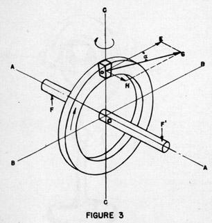 The couple F-F' exerts a force upon this small mass along DH and so accelerates it in this direction. During a short interval of time this acceleration will give the particle a component of velocity DH. The result of combining velocities DE and DH is a new velocity DG different in direction from DE. This is equivalent to a rotation through angle α about axis C-C Therefore the effect of a couple F-F acting about the B-B' axis is a slow rotation of the gyro wheel about the C-C' axis. This rotation is known as precession.
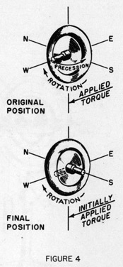 The axis of a freely mounted gyro will tend to turn or precess in such a direction that it becomes parallel to the axis of the applied torque, by the shortest path, and with, the rotation of the wheel in the same direction as the applied torque. See Figure 4.
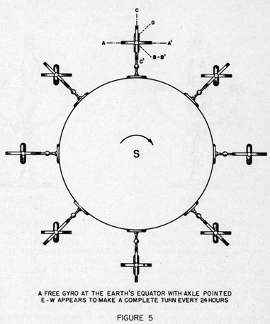 In the case just described it was assumed that vertical axis bearings C-C' were without friction. The extent to which friction is present in these bearings determines the ability of a gyro wheel to maintain its plane of rotation fixed in space against the friction of bearings B-B'. If, to take an extreme case, the supporting frame were locked about axis C-C' (L, Figure 1), the gyro wheel would immediately lose its resistance to the friction of bearings B-B' and so would partake of the earth's rotation just as if the wheel were not spinning. The importance of extreme freedom about axis C-C' is therefore apparent.
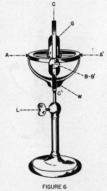 Assume again that the gyro wheel, this time with its pendulous mounting, is placed, wheel spinning, at the earth's equator with the axle horizontal and pointing East-West. This is illustrated in Figure 7. At this time both fundamental properties of the gyro wheel, rigidity of plane and precession, are brought into play. For, as the earth rotates, the axle becomes inclined to the horizontal as illustrated in Figure 8. This raises the weight W against the pull of gravity and consequently applies a force on the gyro about the North-South axis. This force causes precession about the vertical axis C-C' in the direction indicated, so that the gyro axle moves out of its East-West position as shown in Figure 9. As the axle precesses toward the meridian the earth's rotation keeps increasing the angle of tilt of the axle. Since the rate of precession is closely proportional to this inclination, the gyro turns about the vertical at an increasing rate until the axle is on the meridian, Figure 10. Here the inclination and rate of precession are a maximum. Note that it is the righting couple, applied to the inclined axle by the pendulous weight, which causes the compass to precess across the meridian. The kinetic energy of precession, being entirely negligible, plays no part here. After the gyro axle crosses the meridian, the higher end of the inclined axle is to the West of the meridian
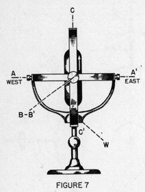
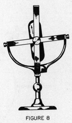
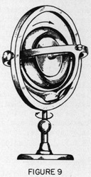
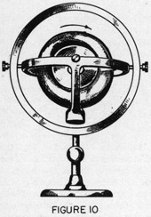
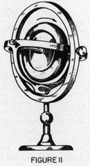
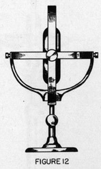
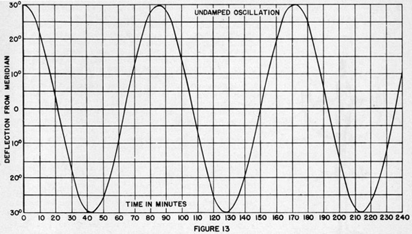
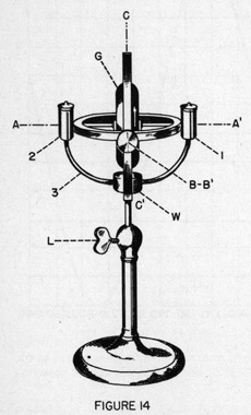 rate of flow is low because a high resistance is offered by the small pipe, 3. By the time the gyro axle has reached a North-South position a considerable quantity of oil has passed from tank 1 to tank 2, resulting in an unbalanced condition opposing the restoring force of weight W. The effect of weight W is therefore reduced as the gyro axle approaches the meridian and the rate of precession is materially reduced. For this reason and because the transfer of oil causes the gyro frame to be balanced before the axle becomes horizontal, precession beyond the meridian toward the West is considerably less than 90°. The oscillation has been partly suppressed or damped. An oscillation of this character is represented by Figure 15. The same action occurs on succeeding oscillations, the flow of liquid always being delayed behind the inclination causing it, so that the gyro wheel finally comes to rest with its axle horizontal and exactly on the meridian. By properly proportioning the gyro wheel pendulous factor and the oil vessels, the initial oscillation may be completely suppressed in two and one half cycles.
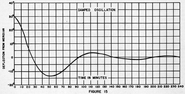
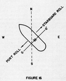 Consider a gyro-compass mounted in gimbals on a ship headed Northwest and rolling violently. It is assumed that the gimbal rings are free of friction and that there is no tilting of the gyro from this possible source. It is assumed further that the gyro axle has settled in its true North-South direction.
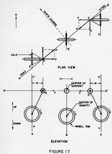 of the gyro. Rolling of the ship causes the center of support, 0, to move back and forth over a large arc, G-G', which is shown as a straight line because it is only this part of the motion which is of importance here. Positions A, A' show the gyro wheel at the extreme position of a roll to port. The center of support here has its maximum acceleration to the Northeast represented by the arrow OD. This force may be resolved into two components OE and OF. The North-South component OE, acting through the vertical distance between center of gravity and center of support, tends to tip the North end of the gyro down.
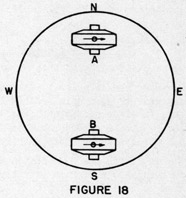 If in some way the compass could be prevented from swinging in the East-West direction, the intercardinal error would be eliminated, for in Figure 17 the distance H would be reduced to zero as when the ship heads East or West. In the Arma Compass two gyros are used so as to stabilize their frames in an East-West sense and at the same time provide directive force.
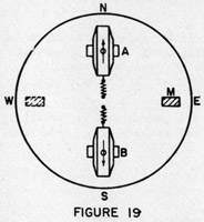 Assume that two gyros spinning in the same direction are mounted on a frame as shown in Figure 18. The directive force is twice that of a single gyro but the stabilization to tilting is zero. If the gyros are mounted on pivots and held by light springs in the position shown in Figure 19, the frame is stabilized to tilting up or down on the East or West side. A small mass M placed on the eastern edge of the frame causes the gyros to precess at equal rates in opposite directions on their pivots. The frame is stabilized and does not deviate when the mass is added because each gyro precesses about its own pivot. If the mass is left in place for a long time, the centering springs will limit the gyro unit's precession and the frame will lose its stabilization. However, for a torque applied first one way and then the other, which is the condition imposed by a rolling ship, the frame is effectively stabilized. The directive force of the arrangement pictured in Figure 19 is zero.
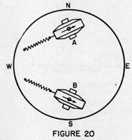 If the gyros with their centering springs are turned at an angle, Figure 20, they precess in opposite directions when a weight is added on the East side of the frame, and so stabilize the frame in this direction. If a weight is applied at the North side of the frame, both gyros precess in the same direction and carry the frame with them. In order to make sure that the frame follows the gyros exactly, when they precess in the same direction, and to prevent the frame turning at all when they rotate in opposite directions, the two gyros are connected by a link mechanism which ensures their turning relative to the frame in equal and opposite angles only. The construction is shown in Figure 21. This
construction prevents tilting of the gyro frame due to rolling of the ship and eliminates the intercardinal error. The gyro frame assembly will be referred to hereafter as the sensitive element.
If the gyros with their centering springs are turned at an angle, Figure 20, they precess in opposite directions when a weight is added on the East side of the frame, and so stabilize the frame in this direction. If a weight is applied at the North side of the frame, both gyros precess in the same direction and carry the frame with them. In order to make sure that the frame follows the gyros exactly, when they precess in the same direction, and to prevent the frame turning at all when they rotate in opposite directions, the two gyros are connected by a link mechanism which ensures their turning relative to the frame in equal and opposite angles only. The construction is shown in Figure 21. This
construction prevents tilting of the gyro frame due to rolling of the ship and eliminates the intercardinal error. The gyro frame assembly will be referred to hereafter as the sensitive element.
 In the Arma Mk. 7 Compass the gyro axles are inclined 35° from the North-South axis. The directive force and stabilizing effect of an inclined gyro may be found by resolving its angular momentum into North-South and East-West components. The table below shows the individual and total values where the effect of a single gyro is taken as unity.
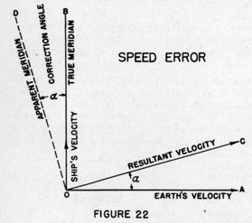
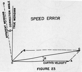
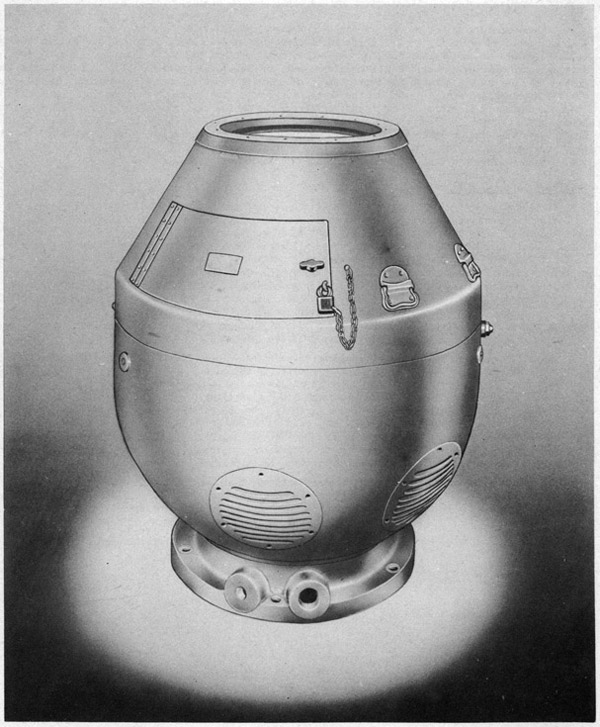
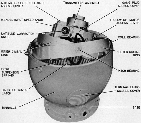
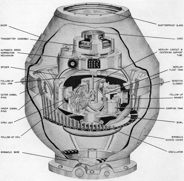
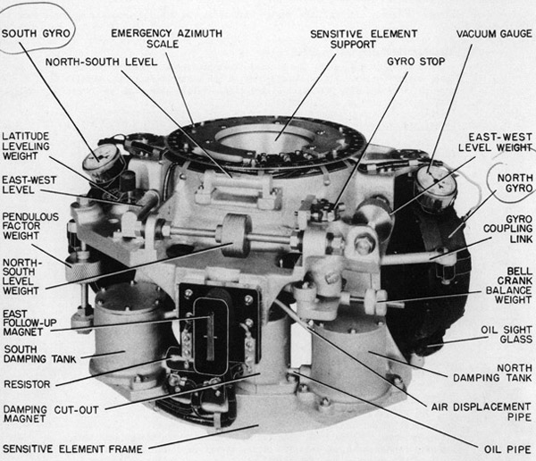
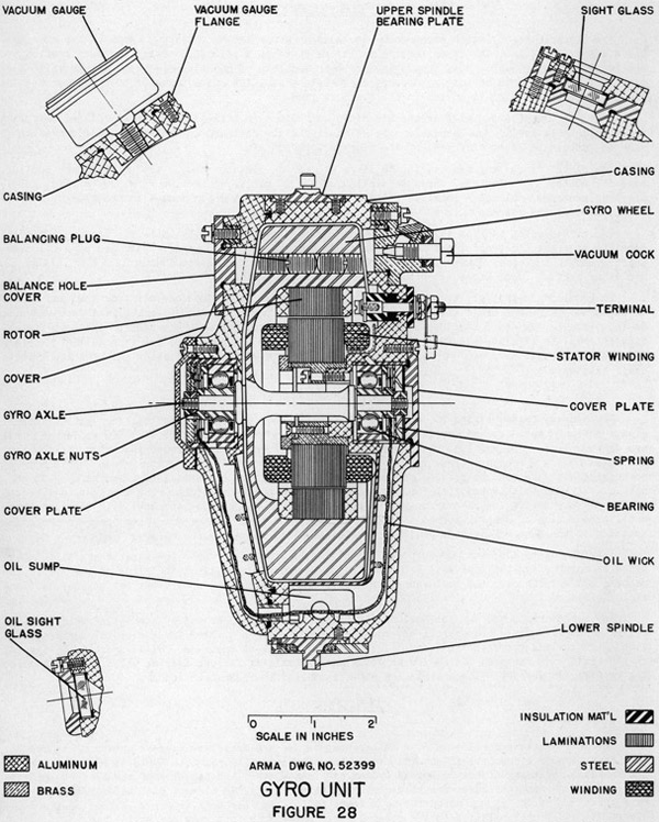
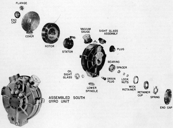
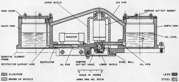
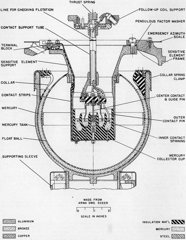
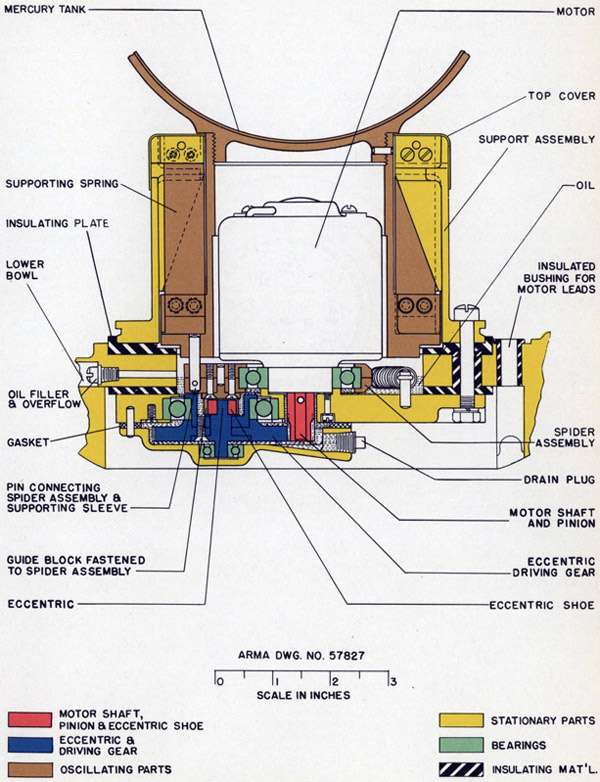
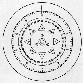
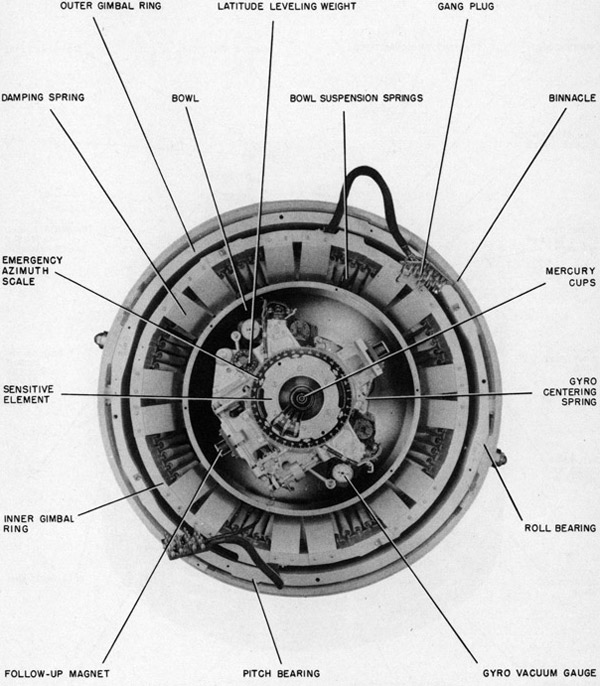
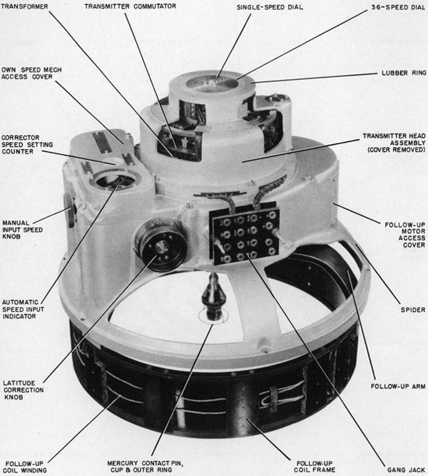
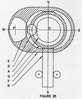 By means of an accurate lead screw, this speed quantity is introduced into a slotted link, which transmits the motion to the eccentric bearing. The fulcrum point of this link is a pivot mounted on a slide capable of being moved at right angles to the direction of the eccentric travel. Movement of this pivot increases or decreases the effect of the speed input upon the eccentric bearing. This has the effect of multiplying the speed input by a varying quantity. The pivot is moved with another lead screw actuated by the latitude knob. This knob is graduated from 0 to 70 degrees in such a manner that the pivot location for any setting will multiply the speed input by the secant of the latitude. The resulting eccentric bearing movement is then proportional to the product of the ship's speed and the secant of the latitude. The position of the eccentric bearing should always satisfy the following equation:
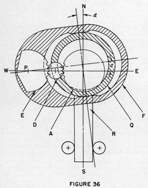 Figure 35 shows the elements of the eccentric bearing mechanism in the position they occupy when the ship is headed North before any correction has been made. A gear A is pinned to the upper end of the follow-up coil support stalk. It meshes with idler pinion D which also meshes with gear E rigidly fastened to a fork F. The letters are the same as used in Figures 40 and 41. The sides of the fork rest on a large diameter ball bearing Q. When there is no correction this bearing is centered as shown in Figure 35. If the ship is travelling North, the sensitive element axis settles to the West of true North, and a correction is automatically introduced by the mechanism described previously. This correction causes rail R to move bearing Q Northward as shown in Figure 36. Fork F is rotated about its center P, and through idler pinion D turns gear A, so that the follow-up axis is turned through the correction angle, and its East-West axis is opposite the sensitive element magnets. The card reads the corrected North position, the sensitive element has settled in its new position, and the follow-up system is in equilibrium, because the coil axis is opposite the follow-up magnets.
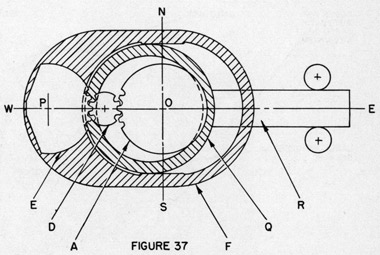 If the ship changes its course to due West. the sliding rail R, and bearing Q, turning with the spider, occupy the positions shown in Figure 37. Being geared to the follow-up coil, the fork pivot remains in the West but the fork is rotated back to its original Position since the displacement of Q is now directly toward the fork axis P. The correction introduced by the mechanism has been reduced to zero which is as it should be because there is no speed error on a Westerly course. The action of the mechanism is such as to convert the correction for a Northerly course into the proper correction for any heading the ship may have.
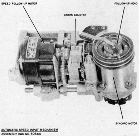
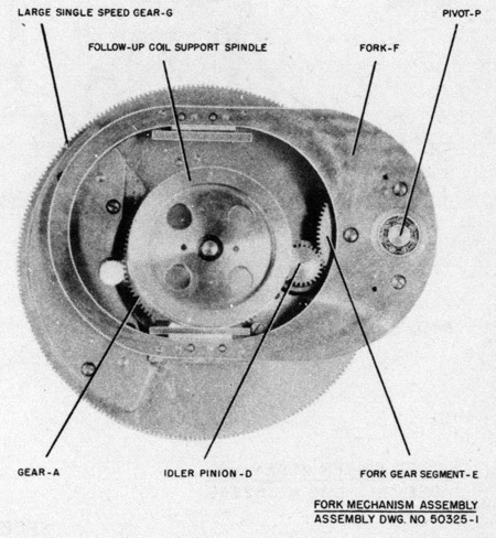
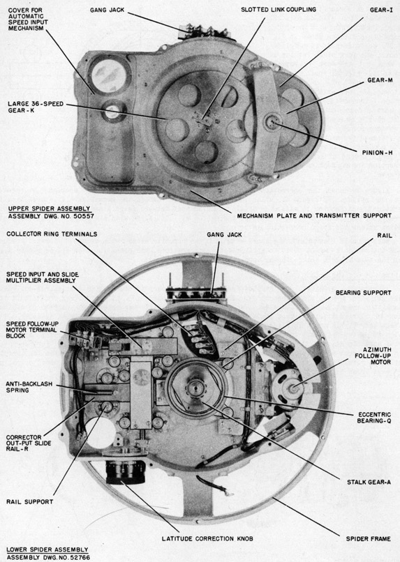
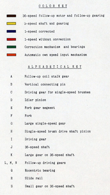
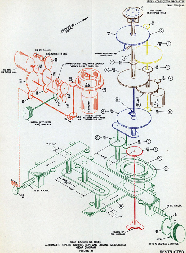
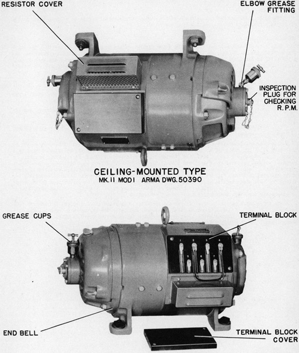
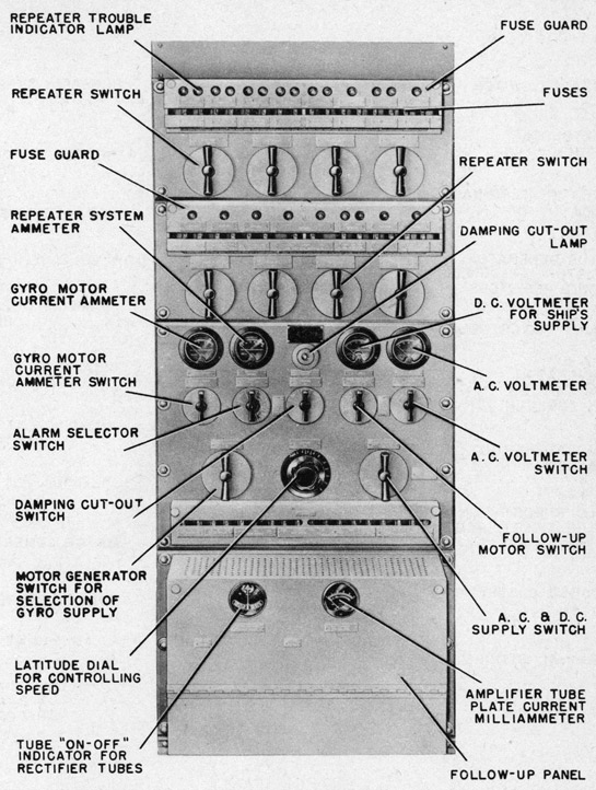
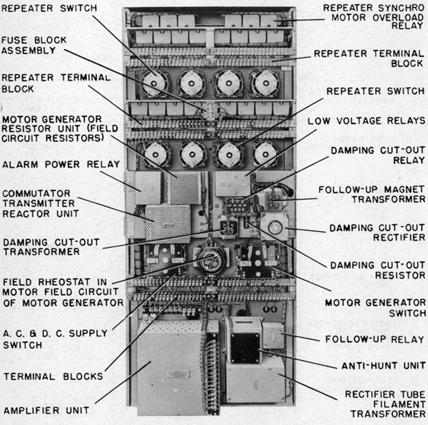
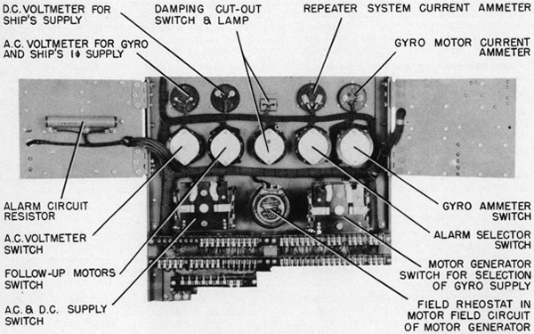
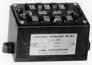
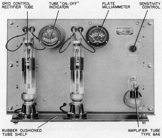
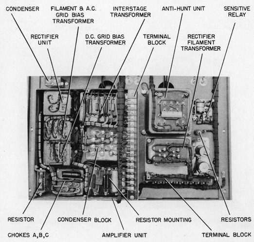
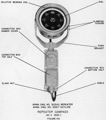 In its simplest form the repeater consists of a compass card fixed to the end of the shaft of a synchro motor whose rotor turns in synchronism with the master compass transmitter brushes.
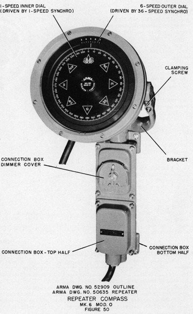 The Mark 6 Mod. 0 repeater has two concentric dials as shown in Figure 50. The inner dial, which resembles that on a single dial repeater, is driven through gearing by a synchro connected to the 1-speed transmission. The outer dial is driven from the 36-speed transmission through a 6 to 1 gear reduction. It makes six revolutions to one of the inner dial, and permits readings to 0.10 degree. So that the more rapid movement of the outer dial will not distract the eye from the inner 1-speed dial a mask is provided which covers all but 5 divisions of the outer dial.