There follows a table which is intended to be of help in finding the source of various troubles which may be encountered. It is important to remember that WHEN TROUBLE IS ENCOUNTERED THE FIRST THING TO DO IS TO DISCOVER THE SOURCE OF THAT TROUBLE. Consult the table which follows. Check to make sure trouble exists. Go over the possible causes carefully and make the simplest checks first. When the simpler checks have been made and the trouble is not found, check other possible causes. Read Page 101, on "Adjustments and Balances" before disassembling any parts or making any adjustment.
• Loss of Vacuum
A gyro unit may lose vacuum for several reasons. The trouble may be due to a leak, in which case it will continue to get worse, or it may be caused by volatiles within the casing. These volatiles reduce the vacuum more when the case is hot than when it is cold. For this reason the vacuum may continue to drop because the lowered vacuum results in overheating which further reduces the vacuum. Any trouble which results in overheating is likely to result in a reduction of vacuum even though the case is tight and has been properly evacuated.
If the vacuum drops and the unit overheats in service, check the gyro supply voltage. If this is normal, it will be necessary to reduce the speed of the wheels by setting the latitude dial to 50 degrees. Usually this must be done if the vacuum gauges reading drops below 29 inches. Under the reduced speed the vacuum will usually improve. If, however, it continues to drop and the compass must be kept in service, open the air valves in both gyro casings and set the latitude dial to 55 degrees.
The Ballistic Deflection will not have the correct value when the wheels are running below normal speed. This will result in a temporary error on a turn or change of North-South speed component. The error is small and damps out about an hour after the turn or speed change is completed.
TROUBLE
POSSIBLE CAUSE
REMEDY
Loss of vacuum
Leaking gasket.
Defective bearing.
Defective stator.
Defective rotor.
Volatiles in oil.
Gyro net properly evacuated.
Replace gasket.
Replace bearing.
Replace stator.
Replace rotor.
Replace with gyro oil.
Re-evacuate as instructed on page 118.
Excessive current in gyro circuit
Loss of vacuum.
Defective stator.
Defective rotor.
One gyro lead open.
Short in gyro circuit.
See "Loss of vacuum" above.
Replace stator.
Replace rotor.
Make circuit complete.
Clear short circuit.
Noisy or hot gyro unit
Excessive gyro current.
Loss of vacuum.
Defective bearing.
See "Excessive current in gyro circuit".
See "Loss of vacuum".
Replace bearing.
Excessive vibration of gyro unit
Defective bearing.
Gyro wheel out of balance.
Replace bearing.
Replace gyro unit. Send wheel to repair ship or station for rebalancing.
Element refuses to settle
Element not level.
Irregular gyro wheel speed.
Bring N-S bubble on scale. See page 102.
Check wiring. Fix loose connections. Check gyro current in each phase. Check gyro speed.
96
TROUBLE
POSSIBLE CAUSE
REMEDY
Element refuses to settle (Continued)
Obstruction to flow of damping oil.
Make sure damping cut-out switch is "On" if ship is at anchor or on "Automatic" if it is in motion. Check damping. See page 103.
Error in settling point
Follow-up coil support displaced.
Reset coil support. See page 107.
Improper flotation.
Check flotation. See page 102.
Bent contact pins.
Remove spider and straighten pins.
Oscillator not working.
Check wiring and connections. Repair defect.
Spider and bowl not level.
Remove obstruction which prevents bowl from standing approximately level.
Speed correction improperly set or mechanism out of adjustment.
If error occurs when ship is on a straight course but not when ship is at anchor, check speed correction mechanism adjustment. See page 92.
Variable error in compass
Improper mercury flotation.
Check flotation. See page 89.
Element not horizontal when running and settled.
Look for foreign objects on sensitive element. Bring bubble on North-South level on scale. See page 102. Check position of latitude leveling weight. See page 84.
Gyro coupling linkage not free to move.
Check freedom of gyros to turn about vertical when wheels are not running.
Error on turn.
See "Error on turn" below.
Error on turn
Failure of damping cut-out.
Make sure damping cut-out switch is in "Automatic" position. Check continuity of circuit.
Latitude improperly set on latitude dial.
Set dial to correspond to ship's latitude.
Bent contact pins.
Remove spider and straighten pins. See page 112.
Loose connection.
Inspect all connections for tightness.
Insufficient mercury in collector rings.
Add mercury until depth in outer cup is 3/4", middle 1/2", and center guide bearing half way to the top.
Oscillator mechanism not operating.
Check continuity of circuit. Replace defective bearings.
Shifting weight.
Check locknuts on all weights for tightness.
Wrong pendulous factor.
Look for foreign object on element. Check undamped period. See page 102.
Speed correction mechanism out of adjustment.
Check adjustment. See page 92.
97
TROUBLE
POSSIBLE CAUSE
REMEDY
Dead space in follow-up
Sensitivity control improperly adjusted.
Make new adjustment. See page 108.
Follow-up mechanism turns hard.
Check by turning 36-speed dial by hand when follow-up motor switch is turned to "Off".
Defective tube.
Replace tube.
Follow-up motion erratic
Loose connection or poor contact.
Check connections of follow-up coil circuit. Check contact between slip rings and brushes and in terminal block plugs.
Alarm flashes
Low A.C. supply voltage.
Raise supply voltage.
Low gyro supply voltage.
See "Low gyro supply voltage".
Follow-up not following.
Check follow-up circuit.
Low gyro supply voltage
Low D.C. voltage.
Check D.C. voltage.
Short in generator circuit.
Remove short circuit.
Defective generator.
Switch to spare motor generator set and repair defect.
Generator not up to speed.
Check motor field circuit. Switch to spare motor generator.
Generator field circuit defective.
Repair defect.
The following tabulation will aid in locating troubles in the automatic speed corrector.
TROUBLE
POSSIBLE CAUSE
REMEDY
Follow-up hunts
Wrong dead space.
Check brush adjustment.
Excessive sparking at follow-up head
Defective resistor or condenser in circuit.
Replace resistor or condenser.
Follow-up does not operate
Burned follow-up head contacts.
Clean and check for excessive sparking.
Defective 1-mfd. condenser.
Replace condenser.
Defective follow-up motor.
Replace motor.
Follow-up motor clutch slipping.
Clean clutch, and check its torque.
Speed receiver synchro does not operate
Underwater log transmitter not functioning.
Check speed input to panel. Check gearing for jamming.
Defective synchro.
Replace synchro.
98
• Follow-up Troubles
The following tables are included as an aid in locating follow-up troubles. The material given here is not a detailed analysis of all possible follow-up troubles, but rather a condensed outline of tests for the most probable sources of trouble encountered in operation. If it is desired to work on the follow-up while the compass is still in operation, remove the fuses on the control panel marked "Follow-up System" and use the emergency azimuth scale for obtaining headings.
When servicing the follow-up make all the simple checks first. Look for broken or burned out tubes and loose connections. Look for foreign objects which might short out parts of the circuits. After these checks have been made, if trouble still exists, an attempt should be made to locate the defective circuit. The two meters on the front panel will help to locate the faulty section.
In using the follow-up meters to find the circuit in which trouble exists, read the tube "On-Off" indicator first (instrument on left, Figure 47). If the needle is to the left, for example, tube No. 1 should be operative. If it is not, there is something wrong with the tube or its circuit, such as a defective follow-up motor armature or follow-up motor switch in "Off" position. If the "On-Off" indicator shows no deflection but the amplifier plate current meter (instrument on right, Figure 47) shows abnormally low current indicating that a large signal is present in the amplifier tube, then the trouble lies in the interstage coupling. The plate current should return to normal (1.5 to 2.5 milliamperes) when there is no signal input.
Having determined the approximate location of the trouble, check the voltage drops across the various units in the circuit with the values shown in Figure 72. These values, the average of several tests made on different follow-up panels, were obtained while the master compasses were functioning properly, and were measured with a Weston type 301 meter having an internal resistance of 1000 ohms per volt. The units being tested should check within ± 10%. If any large differences are found, remove the fuses, as outlined above, and check the D.C. resistance of the circuit in question with the values given in the following table. These units should also check within ± 10%.
TABLE OF ELECTRICAL VALUES OF FOLLOW-UP PARTS
(Symbols correspond to those on Figures 61 and 72).
C4
Condenser, 0.015 mfd., 200 volts
C5
Condenser, 0.015 mfd., 200 volts
C6
Condenser, 0.1 mfd., 200 volts
C7
Condenser, 0.1 mfd., 200 volts
C8
Condenser, 0.5 mfd., 200 volts
C9
Condenser, 0.5 mfd., 200 volts
C10
Condenser, 0.015 mfd., 200 volts
C11
Condenser, 0.165 mfd., 200 volts
C12
Condenser, 4 mfd., 200 volts
C13
Condenser, 4 mfd., 200 volts
C14
Condenser, 4 mfd., 200 volts
C15
Condenser, 4 mfd., 200 volts
C16
Condenser, 4 mfd., 200 volts
C17
Condenser, 4 mfd., 200 volts
C18
Condenser, 8 mfd., 200 volts
C19
Condenser, 4 mfd., 115 volts
E1
Rectifier, copper oxide
E2
Rectifier, copper oxide
E3
Rectifier, copper oxide
L1
Choke coil, 3 hen., 70 ohms
L2
Choke coil, 3 hen., 70 ohms
L3
Choke coil, 3 hen., 70 ohms
P1
Potentiometer, 125,000 ohms
R9
Resistor, 1, 200 ohms, 25 watts
R10
Resistor, 20 ohms, 120 watts, (2) 10 ohms in series
R11
Resistor, 100,000 ohms, 1 watt
R12
Resistor, 60,000 ohms, 1 watt
R13
Resistor, 60,000 ohms, 1 watt
R14
Resistor, 60,000 ohms, 1 watt
R15
Resistor, 60,000 ohms, 1 watt
R16
Resistor, 60,000 ohms, 1 watt
R17
Resistor, 60,000 ohms, 1 watt
R18
Resistor, 4,000 ohms, 1 watt
R19
Resistor, 4,000 ohms, 1 watt
R20
Resistor, 15,000 ohms, 1 watt
R21
Resistor, 15,000 ohms, 1 watt
R22
Resistor, 185 ohms, 25 watts
R23
Resistor, 100,000 ohms, 1 watt
R24
Resistor, 500 ohms, 2 watts, (2) 1000 ohms in parallel
R25
Resistor, 100,000 ohms, 1 watt
R26
Resistor, 500,000 ohms, 1 watt
R27
Resistor, 100,000 ohms, 1 watt
T1
Transformer, input
T2
Transformer, interstage
T3
Transformer, amplifier filament
T4
Transformer, A.C. grid bias
T5
Transformer, rectifier filament
T6
Transformer, D.C. grid bias
T7
Transformer, anti-hunt unit
T8
Transformer, amplifier plate supply
V1
Amplifier tube, type 6A6
V2
Rectifier tube, type C6A
V3
Rectifier tube, type C6A
99
ADJUSTMENT AND REPAIR D.C. RESISTANCE OF FOLLOW-UP CIRCUITS
Circuit
Terminals
Correct Effect (Ohms)
Incorrect Effect
Probable Cause of Incorrect Effect
Input
S1 and S2 on amplifier unit block
19
Over 100 ohms
Open winding on transformer T1.
Grid
3 on tube V1 and 4 on choke coil unit
over 500,000
Open
Open winding on transformer T1 or open resistors R26, 27.
Low
Shorted condenser C10 or resistor R26.
D.C. Supply
1 and 4 on choke coil unit
1, 300
Open
Open choke L1.
1, 800 ohms
(1) resistor open on R24.
D.C. Supply
5 and 8 on choke coil unit
over 100,000
Open
Open resistor R25 or chokes L1, L2.
2 and 4 on choke coil unit
over 250,000
Open
Open choke L1, resistor R23, potentiometer P1.
Plate
2 on interstage transformer and 5 on choke coil unit
7, 150
Open
Open winding on transformer T2, plate current meter, alarm relay, or choke L3.
Rectifier Tube #1 Grid
1 on D.C. grid bias transformer and G1 on terminal block
100,000
Open
Open resistors R12, 20 anti-hunt winding, or winding on transformers T2, 4.
Rectifier Tube #2 Grid
2 on D.C. grid bias transformer and G2 on terminal block
100,000
Open
Open resistors R13, 21, anti-hunt winding, or winding on transformers T2, 4.
Rectifier* of Tube #1
1 and 7 on D.C. grid bias transformer
3,000 to 4, 500
5,000 ohms
Open resistor R20.
High
Open resistor R19.
Short
Shorted condenser C9.
Rectifier* of Tube #2
2 and 8 on D.C. grid bias transformer
3,000 to 4, 500
5,000 ohms
Open resistor R21.
High
Open resistor R18.
Short
Shorted condenser C8.
Anti-Hunt
AH23, AH24 on amplifier unit terminal block
3, 190
60,000 ohms
Open winding in anti-hunt.
Short
Shorted condenser C6.
Anti-Hunt
AH21, AH22 on amplifier unit terminal block
3, 190
60,000 ohms
Open winding in anti-hunt.
Short
Shorted condenser C7.
Anti-Hunt
25 and 26 on anti-hunt unit
6, 160
100,000 ohms
Open winding in anti-hunt.
4, 800 ohms
Shorted condenser in anti-hunt.
Anti-Hunt
35 and 36 on anti-hunt unit (follow-up motor switch off)
20
40 ohms
(1) resistor open on R10.
Follow-up Motor Field
Across follow-up motor field at motor (switch off)
2,000
Open
Open field coil.
Follow-up Motor Armature
Across follow-up motor brushes at motor (switch off)
4.5
Open
Defective brushes.
* In circuits in which there is a rectifier, changing the polarity of the test leads changes the resistance of the rectifier. Generally, a rectifier will continue to function properly even though its resistance varies greatly. Hence, look for some other defective part before replacing a rectifier.
All adjustments and balances are carefully checked at the factory before the compass equipment is shipped. If the equipment is properly handled and operated, further adjustment will very rarely be necessary until parts are replaced.
• In Case of Trouble
As long as the compass is operating satisfactorily, do not disassemble the parts or move any weights. When an irregularity of operation is noted, look for the cause before attempting an adjustment. Consult the table of "Troubles and Remedies", page S5, to find possible causes. Check the control panel instruments to make sure the supply voltage and frequency are normal, and that the gyro current is about 1.7 to 2.6 amperes in each phase. Check gyro voltage and D.C. voltage. See page 86 for correct values.
Go over the possible causes of trouble listed in the table, making the simplest checks first. In the great majority of cases the trouble is caused by some simple defect.
Unless a weight has worked loose or a part has been replaced, an adjustment of the sensitive element balance is very rarely necessary. Even when a part has been replaced a rebalance in many cases is not necessary. If, however, it appears that an adjustment must be made, proceed as follows:
(1) Check voltages of A.C. supply, D.C. supply, gyro supply, and gyro current. Normal values are given under OPERATION, page 86.
(2) Check vacuum readings of both gyro units. Vacuum should be about 29 inches.
(3) Check setting of latitude dial, and motor generator speed.
(4) Look to see if mercury tank oscillator is working.
(5) Go over control panel, follow-up panel and master compass, looking for loose connections, shorts, or other wiring defects.
(6) Determine whether or not follow-up system is operating by comparing card reading with emergency azimuth scale reading. The card and emergency azimuth scale read the same only when the speed corrector is set at zero. Turn follow-up motor switch off, turn 36-speed dial by hand to put error in card reading, then turn follow-up motor switch back on. Motor should bring card back immediately to its correct position. Move 36-speed card back and forth to check "dead space" which should be practically zero.
(7) Feel the gyro units to detect abnormal heating or vibration. Make sure both wheels are running.
(8) Go over adjustable weights and locknuts on sensitive element to see if any have worked loose, but do not move the weights.
(9) Go over entire sensitive element very carefully looking for screws, nuts, mercury, or other foreign material which might be resting on frame or in some unseen place, as, for example, under the damping tanks or around the damping cut-out magnet.
(10) Check position of bubble in North-South level. This bubble should be on scale after compass has settled. If it is not, proceed according to instructions on page 102.
(11) Check damping cut-out circuit to make sure valve operates when contacts close.
(12) Shut down compass. After gyro wheels have stopped turning, check freedom of gyro units about the vertical. If there is evidence of sticking or excessive friction, remove element, disconnect coupling links, check freedom of gyro case rotation and of link motion. Make certain that the gyro coupling stop screws are correctly adjusted. Normally the gyro axles are inclined 35° from the North-South axis. At the extreme outward position (using the gyro centering spring stud as a reference point) the axles are inclined 20° and at the extreme inward position the axles are inclined 42°.
(13) Check freedom of element to tilt and rotate. It should, as nearly as can be determined, be perfectly free to rotate. After a slight push it should continue to rotate for many minutes. Resistance to motion indicates bent contact pins or improper flotation.
102
(14) Lay a straight-edge across top surface of element to see if it is level with a reference line on the contact pin support tube. Add or remove mercury to obtain this condition.
(15) If the trouble is an error on turning, or an occasional open gyro circuit as the ship rolls, remove the spider assembly (see page 112) and inspect for bent contact pins and insufficient or dirty mercury in contact cups. The mercury in the outer cup should be 3/4 inch deep, the middle cup 1/2 inch deep, and the center guide bearing half way to the top. Be sure the mercury is clean. Before filling the cups, wipe them out with a damp cloth and allow them co dry.
(15) Remove damping tank covers and examine fluid. If dirty, flush out tanks and refill with clean oil. See page 93.
• Sensitive Element Level Adjustments
After all the items above have been carefully checked the level bubbles may be brought on scale. Be sure that the compass has been running at least four hours and has settled. Bring East-West bubble to center of scale by shifting the weight which is on a rod parallel to East-West bubble tube axis. This adjustment is not critical. If the bubble is not off center more than 1/8 inch, no adjustment need be made.
After East-West bubble is centered, or approximately so, as its position is not critical, allow compass to settle again and bring North-South bubble on scale by turning the North-South level adjusting weight. One-half turn of the weight will advance the bubble fifteen divisions when it is fully on scale.
• Pendulous Factor Adjustment
Always check the pendulous factor before making this adjustment. No adjustment should be necessary unless the weights nave worked loose or parts have been replaced. Look for other trouble first. Check all the 16 items above. Rarely is a pendulous factor adjustment necessary. If the factor is wrong there will be a temporary error on turns or upon sudden change of ship's speed. When the ship is anchored, pendulous factor does not affect the settling point.
The pendulous factor is a function of the distance between the center of gravity and the center of support of the sensitive element. It determines the undamped period of the element. This period should be the same for all latitudes when the latitude dial is correctly set. The undamped period is measured as follows when the ship is not in motion:
(1) Set the latitude dial on the control panel very accurately to the correct ship's latitude. Check the motor generator speed. See pages 85 and 106.
(2) Determine the settling point of the compass.
(3) Turn the damping cut-out switch to "Off".
(4) Precess the element 30 degrees to the East of the meridian by pressing down lightly on the South side of the element. Bring the North-South bubble to several divisions South of the settled position by pushing on the bubble tube in the direction the bubble should go. This is done so that the element will start to precess away from the meridian, reach a peak shortly, and then go back toward the meridian.
(5) Allow the element to oscillate across the meridian several times, recording the exact time when the element crosses its settling point. The North-South bubble will cross its settling position when the oscillation amplitude reaches a maximum. The oscillation should not diminish at each swing by more than about two degrees. A greater reduction of amplitude indicates excessive friction at the contact guide pin, in the mercury, or leakage of the damping fluid past the cut-out valve.
If the ship's heading is changing, as it may when the ship is anchored but not moored to dock, the oscillations cannot be determined from the card reading. The period, however, may be taken as the time required for the bubble to cross any position on the scale, come back, and cross the same position in the same direction; or relative bearings of a terrestrial object may be taken from an alidade.
From the readings recorded during the undamped oscillation, determine the time required for a complete oscillation from a peak on one side of the meridian back to the next peak on the same side. Check by determining the time elapsing from the first crossing of the meridian (settling point) until the next crossing in the same direction. This time is the undamped period and should be 85.7 minutes ±2 minutes at any latitude providing the latitude dial is set correctly.
103
If the period is too long, it may be reduced by lowering the pendulous factor weight. If the period is too short, it maybe corrected by raising the weight. Turning the weight five turns changes the period one minute. Make no changes unless the motor generator speed has been checked.
• Damping Percentage Adjustment
The percentage of damping is a function of the rate of flow of oil between the two damping tanks. If the flow of oil is reduced, the damping percentage will be too low. Regulation of the oil flow is adjusted at the factory. This is done by changing the length of a round rod fitted snugly into the oil line. A flat along one side of the rod permits the oil to flow. No change should be made in this adjustment. Insufficient damping is due to dirt in the fluid or use of the wrong fluid.
To determine whether or not the damping percentage is correct, proceed as follows when the ship is not in motion:
(1) Proceed as outlined in steps (1) to (4) of "Pendulous Factor Adjustment".
(2) When the element reaches the peak as explained in step (4) of "Pendulous Factor Adjustment", turn the damping switch to "On".
(3) Allowing the element to precess back and forth across the meridian, record the amplitude of the original displacement and the following two peaks.
(4) The first swing past the meridian should carry the card about fifty percent of its original displacement from the meridian, that is about 15 degrees. The second oscillation should be reduced by about 80%, that is to approximately 3 degrees. The damping percentage is the average of these two percentages and should be between 55% and 80%. Unless the damping is outside of these limits, no attention is necessary.
If the damping percentage is below the lower limit, drain out the damping oil, flush out the tanks, valve, and pipe thoroughly, and fill to a depth of 1-1/4" in each tank with clean oil. See page 93. Check the damping percentage to make sure the proper value has been restored.
If the damping percentage of the compass is too high, friction to movement of the sensitive element is indicated. Check flotation and contact pins.
• Bell Crank Adjustment
Each gyro is coupled to a bell crank by a link. When the gyro units precess through equal and opposite angles, as occurs when the ship rolls, the links move and the bell crank turns. In order to preserve the balance of the sensitive element under this condition, weights are placed on the bell crank at the factory. Unless extensive replacement of parts is made on the element, this adjustment will not require changing. Gyro units are carefully balanced about the vertical and horizontal axes so that changing these units does not necessitate a readjustment of the bell crank weights.
If extensive repairs have been made on the element, or if the weights have been removed and it is desired to check the balance, proceed as follows:
(1) Shut down the compass and let the gyro wheels stop rotating.
(2) Turn the damping switch to the "Off" position and level the element by placing several small weights about the element.
(3) Remove the gyro centering springs. Be sure the element is floating properly.
(4) Turn the gyro units so that the coupling links move away from each other to their extreme position.
(5) Let the element come to rest. Note position of East-West and North-South bubbles.
(6) Turn gyro units to other extreme position and let the element come to rest.
(7) Read bubble positions.
If the adjustment is correct, the North-South level bubble will not move more than 5 divisions nor the East-West level bubble more than 1/4 inch. If, instep (4), the bubble in the East-West level moves toward the West, the knurled bell crank lever weight is too far out on the thread of the rod. Movement of the North-South bubble is controlled by a permanent weight under one end of the lever.
104
• Gyro Unit Balance
Each gyro unit is balanced at the factory about the vertical axis and also about the horizontal axis. Weights are fixed to the case to obtain these balances and to make the weight of each gyro unit the same as that of every other. This insures interchangeability of the units. These permanent weights should never be removed, or changed in any way.
• Gyro Wheel Balance
It sometimes happens that a gyro wheel requires rebalancing. This work should be attempted only where the necessary facilities are available and by one experienced in gyro wheel balancing.
When it is found that there is excessive vibration in a gyro wheel, the trouble is quite likely due to a defective bearing. The bearings should be replaced one at a time in accordance with the procedure outlined on page 117. After the bearings have been replaced and it is found that the wheel still will not run smoothly, the wheel may be rebalanced.
First the wheel must be put in a static balance, that is, it must be balanced while not running. This is absolutely essential, because no amount of adjusting will bring about a running, or dynamic, balance if the wheel is not in static balance.
Remove the balance hole cover and exhausting valve from the gyro case. Attach a suitable fitting in place of the upper spindle and suspend the unit from a firm support by means of heavy rubber bands of material similar to that used for gaskets between sections of repeater casings. Remove the centering spring stud and place a heavy bent wire in the stud hole to use as a handle by means of which the gyro case may be jiggled, so that it vibrates through a small angle about the gyro wheel bearings. Take off both bearing cover plates. Remove the spring from the case side and retainers from both sides. Shift the wheel axially to the center of its end play to free it from end thrust.
Place one of the balance holes in the wheel opposite the hole in the case and jiggle the case as explained above. If the wheel turns, rotate it through 180 degrees and repeat the operation. If it turns in the opposite direction this time, there is an unbalance. Remove one of the threaded balancing plugs from the heavy side of the wheel, take two or three strokes on the end of it with a file and replace. Try the balance again.
Repeat this operation until the wheel will stay perfectly still in any position in which it is placed when the case is vibrated about the wheel axis. A perfect static balance is essential to good running performance. Always keep the ends of the plugs rounded when filing them down, so that they will bear together on their axis of rotation when they are screwed together.
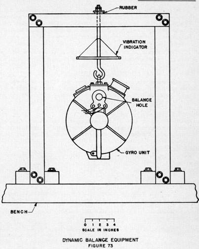
• Dynamic Balance
Dynamic balance is obtained by moving the balancing plugs axially in their threaded holes. After static balance has been obtained, suspend the gyro unit by means of a strong and securely fastened fitting from a firm support. Hang the unit as shown in Figure 73 by means of a stout rod so that it cannot come loose. The rod should extend up through a hole in its supporting member and be fitted with a metal washer and nuts at the top. Let the washer rest on several thicknesses of rubber. Do not hang the unit from a spring or rubber bands.
NOTE: The gyro unit must be suspended for this test in such a manner that there is no possibility of its dropping through failure of a supporting member. Should the unit fall with the wheel turning at high speed, a very serious accident would almost certainly follow.
It is desirable to have some means for indicating vibration amplitude during the balance test runs. This means consists of a 1/4" diameter by 6" long rod suspended by threads as shown in Figure 73. Electric connection to the gyro unit must be made from a motor generator set through an ammeter for measuring the current in each phase. Adjust the motor generator speed control rheostat so that when the generator is started with the gyro connected, the gyro current will be 1 ampere. If the generator is run fast so that a heavier starting current is drawn, the frequent starting of the gyro during the adjustment will cause it to overheat.
105
The gyro wheels have two critical periods, the first about 2,200 R.P.M. and the second about 4,800 R.P.M. All balancing should be done at the first peak. In the method of gyro wheel balancing about to be described, it is necessary to have a pencil which will make a mark on polished metal surfaces, such as #795 Blaisdell.
To balance the wheel, turn on the motor generator and let the wheel slowly increase in speed. As the wheel speed increases, the vibration will also increase. Let the wheel pass through the first critical speed, noting, by the chatter of the rod and by feeling the wheel, the worst amplitude of vibration. Stop the wheel by means of two pieces of bakelite pressed against it through the balance holes in the casing and cover. Be sure to hold the bakelite pieces so that they will Press against the smooth side of the wheel and will not come in the Path of the threaded balancing plug holes. Do not stop the wheel by means of the motor generator, as this causes overheating when frequently repeated.
Start the wheel again and when, as closely as can be judged, the wheel is at the speed of the worst vibration as previously determined, make a mark on the side of the wheel with the pencil referred to above. The wheel should be touched very lightly through the balance hole in the casing side. Stop the wheel with the bakelite pieces and examine the mark made by the pencil. The length of the line is an indication of the unbalance of the wheel; a short line indicating a large unbalance and a long arc indicating a small unbalance. If the line is a short one directly above or very near one of the balance plug holes, move both plugs in that hole a short distance toward the side of the wheel on which the mark appears, remove the mark on the wheel, and repeat the procedure until the pencil traces a complete circle on the side of the wheel.
If the first marking leaves a short line between the two balance holes, move the plugs in both these balance holes toward the side of the wheel on which the mark appears. If the mark is nearer one hole, the plugs in that hole should be moved further than the plugs in the other. After moving the plugs, remove the mark on the wheel and repeat the procedure until the pencil leaves a complete circle on the side of the wheel.
Instead of moving a set of balance plugs in the hole nearest the mark, the same effect is obtained if the plugs in the hole diametrically opposite the mark are moved away from the side of the wheel on which the mark appears. This should be done when the plugs in the hole near the mark are near the side of the wheel.
The wheel is balanced when the pencil traces a circle and should run smoothly through both critical speeds. Continued vibration at higher speed, when the vibration at critical speed is not excessive, indicates a faulty bearing, or possibly a faulty stator or rotor.
106
After the wheel has been balanced it should be evacuated and mounted as shown in Figure 76. If no replacements have been made on the gyro unit, it is not necessary to run a full heat run. Attach thermometers as close to both bearings as possible and adjust the heater voltage or the door so that both thermometers read about 75° or 80° Centigrade. Run the wheel at 18,000 R.P.M. for 20 minutes and tighten up on all gaskets. Run for 20 minutes more and tighten the gaskets again. The wheel is now ready for service.
If parts have been replaced before the wheel was balanced, the gyro unit should be subjected to a heat run in accordance with instructions on page 119.
• Electrical Zero of Commutator Transmitter
Both the single and 36-speed brushes are colored blue, red, and green in a clockwise direction. Three commutator segments, spaced 120° apart, are also colored blue, red, and green. The transmitter is on electrical zero when each brush rests on a segment of its own color. If the contact points of the single-speed blue brush rest in the center of the blue segment, then the red and the green brushes should be displaced from the segments of corresponding color by exactly 1/3 of the width of one segment and one insulating spacer away from the blue brush. The 36-speed brushes are adjusted in a similar manner except that the red and green brushes are displaced toward the blue brush. The outer brushes may be turned by loosening the three screws which clamp the single-speed brush assembly to the driving gear. The inner brushes may be adjusted by loosening the two hub clamp screws.
• Card Adjustment
When the brushes are on electrical zero the compass dials are set on zero. Remove the inner dial and loosen the screws which clamp the 36-speed dial to its hub. The dial may now be turned to its correct position. Replace the single-speed dial and adjust it before tightening its three clamping screws.
• Synchro Brush Dead Space
The synchro brush must have the correct lost motion between the follow-up head segments. This lost motion will be referred to as "dead space". If the dead space is too small, hunting may develop in the follow-up system; if it is too large, the lost motion introduces an appreciable error in the speed corrector. The correct dead space is 0.20 knots. It is measured as follows:
Set the synchro at any convenient speed, and permit the follow-up head to synchronize itself. By carefully moving the "Manual Input, Speed" knob, determine, by reference to the "Corrector Setting, Knots" counter, the amount of follow-up head movement possible between contact points. When the point of contact is reached, the follow-up motor will tend to move the head. The dead space should be between 0.18 and 0.22 knots. If this is incorrect, proceed as follows:
(1) Remove the cover over the corrector mechanism by taking out the four screws.
(2) Remove the two small screws holding the pointer to the synchro shaft. Turn the pointer to one side to expose the brush. It is not necessary to remove the contact spring carrying current to the brush.
(3) The end of the brush is rounded. By bending the conical brush spring to move the brush tip in or out, the dead space may be varied. This spring is delicate. Be careful not to bend it sideways as this could change the electrical zero setting.
• Electrical Zero Setting on Synchro Motor
Unless the brush is correctly positioned upon the synchro shaft, the speed corrector mechanism will be out of step with the underwater log transmitter. The underwater log transmitter reads zero knots when its synchro generator is on electrical zero.
The procedure for checking and readjusting the electrical zero on the synchro motor is as follows:
(1) Turn off the speed corrector input at the control panel. If desired, the azimuth follow-up can be left on.
(2) Set the "Corrector Setting, Knots" counter to exactly zero by means of the "Manual Input, Speed" knob.
107
(3) Remove the cover over the corrector mechanism.
(4) Remove the sheet metal cover over the gang plug on the port side of the compass head.
(5) Connect one side of a source of 115 volt, 60-cycle, single-phase power to terminals 1Y0 and 1Y2; the other side to terminals 1YY0, 1Y1 and 1Y3. The synchro motor will then assume the position of electrical zero. The synchro brush should be approximately in the center of the 0.2 knot dead space near the aft end of the compass.
Warning: Co not leave the power on for more than a few seconds at a time, or the synchro windings will overheat.
If the electrical zero is incorrect, continue as follows:
(6) If the error is less than about 5 degrees, it may be corrected by loosening, slightly, the three clamps holding down the synchro, and rotating the body of the synchro. However, if the error is larger, this should not be done, as the amount of slack in the synchro wiring is limited. For an error greater than 5 degrees, the following procedure should be used:
(7) Remove the bakelite block holding the collector ring brushes. The wires may be left connected, provided the brush assembly is wrapped in a rag to prevent it from touching anything when laid down.
(8) Take out the two screws holding the bakelite hub of the synchro brush to the aluminum hub, and lift off the brush and pointer assembly.
(9) By means of the special socket wrench and puller furnished with the spare parts, remove the nut, and pull the aluminum hub off the tapered synchro shaft. Unless the special puller is used, there is danger of damaging the synchro bearings or shaft.
(10) Energize the synchro, as explained in Step (5), so that it assumes the position of electrical zero. Now, fasten the aluminum hub on the tapered shaft, so that the tapped holes in the hub are as nearly at right angles, as can be judged by eye, with the imaginary line joining the two dead spaces on the follow-up head. Be sure the counter reads exactly 0 knots. The hub can be positioned, by this method, to within 2 or 3 degrees.
(11) Reassemble the brush and pointer assembly, with the brush facing aft, and put back the slip ring brush block. By loosening the synchro motor clamps, as in Step (6), rotate the synchro for exact position. Do not loosen the clamps enough to permit unmeshing the follow-up head gear.
• Gimbal System
With the sensitive element and spider completely assembled and in place, the gimbals are balanced so that the compass dials are level with respect to both fore and aft, and the athwartship axes. This is accomplished by adding a weight or weights to the inner gimbal ring. These weights are permanently attached and should not require changing at any time.
• Spring Damps
The 16 spring damps should all have about the same tension so as to keep the bowl centered in respect to the gimbal rings. A pressure of 18 to 20 ounces, measured at a point 1/8" above the sawcuts should hold the felts clear of the bowl. If no scale is available, remove the damps and check to see that the mounting ends of the new damps are bent at a 45-degree angle.
• Follow-up Coil
If there is a constant error in the settling point of the compass and the binnacle has been properly aligned, then the follow-up coil is displaced relative to the other parts of the follow-up mechanism. To correct this, loosen the three screws which clamp the follow-up coil to the stalk, turn the coil slightly, and reclamp. Repeat this operation until the settling point is correct.
• Ballistic Adjustment
The latitude dial on the control panel is calibrated to give a motor generator speed proportional to the cosine of latitude. To find the correct motor generator speed, apply the following formula:
M. G. Speed = 3000 (Cosine latitude setting).
108
The motor generator speed may be measured by removing a plug from a bearing cap at one end of the housing and applying a tachometer. Take the average of several readings. A table of motor generator speeds for several latitude settings is given on page 86.
Since the percentage of slip in the gyro motor is nearly constant, the gyro wheel speed is proportional to the cosine of latitude. The gyro wheel speed may be found by multiplying the motor generator speed by the number of pairs of poles in the generator and subtracting 3/5 of 1% from the result for slip. This generator has 6 pairs of poles. The gyro wheel speed is given by the formula:
Gyro Speed = (M.G. Speed) 6 - Slip
When it is desired to measure the gyro wheel speed more accurately, this maybe done by connecting a neon lamp. of the kind used on repeater panels, across one phase of the gyro supply. Hold the lamp close to the gyro sight glass. It will be observed that the spiral line appears to move across the wheel face. Each time the line passes, the wheel has slipped one revolution behind the synchronous speed. The exact value of slip will depend upon the degree of vacuum, the latitude setting, and other factors, but is usually between 1/2 of 1% and 1%.
• Follow-up System
On the follow-up panel is a sensitivity control which fixes the gain of the amplifier. The setting of this dial is not critical. If the sensitivity is too low, the torque produced by the follow-up motor for a given displacement of the dials will be low, or there may even be a small "dead space" within which the follow-up will not operate the dials. A high setting of the sensitivity control places an unnecessary load on the system. Ordinarily the adjustment is placed about half way between the upper and lower limits. When the 36-speed dial is displaced by hand, in either direction, the follow-up motor should return it to the same position with no appreciable dead space.
A milliammeter indicates the plate current of the 6A6 tube. Normally this current is about 1.5 to 2.5 milliamperes for a 115-volt, 1-phase supply.
If the follow-up system fails, look for shorts or loose connections. Check the follow-up circuit for voltage and resistance values. See pages 98 and 99 for normal values. The voltages were measured with the follow-up system synchronized, the card and the coil following the element at all times. 0heck the follow-up motor field and armature for possible burn-outs. An extra motor is included in the spare parts box.
• Follow-up Relay
When the follow-up coil is displaced from its normal position, the 6A6 tube is overloaded, causing the plate current to drop. The relay should be adjusted to operate when the current falls approximately 0.7 milliamperes below the normal value. This adjustment may be made by changing the spring tension. The contact points should be adjusted so that while the contact is open, there is a small space between the armature and magnet core to prevent sticking due to residual magnetism. When this contact is closed, the armature should be sufficiently close to the magnet to break the contact when the current returns to normal.
• Low-Voltage Relays
The low-voltage relays may be adjusted in the same manner as the follow-up relay. These relays should be set to operate when the voltage drops to about 80% of the full load voltage for the supply relay, and below 15 volts for the gyro supply relay.
• Repeater Cards
To check a repeater, put the commutator transmitter exactly on electrical zero. If the repeater is properly wired, the armature will take up a position such that a line on the shaft is opposite another line on the casing. The card should then read zero. To correct an error in the zero reading, loosen the nut which holds the card to the shaft and turn the card to zero. A special wrench for this purpose is included among the spare parts. The double dial bearing repeater is adjusted by loosening the screws which clamp the dial, and turning the latter to remove the error.
109
• Commutator Slip Ring Brush Adjustment
On the main commutator molding are three bronze slip rings with "L" shaped bronze brushes running on them. The pressure on each brush arm should be between 3 and 4 ounces. Adjustment may be made by bending the brush spring.
Three brushes, having equalized silver shoes, run on vertical bronze slip rings. Adjustment to a pressure of between 3 and 4 ounces may be made by bending the arms.
The single and 36-speed bronze brushes running on the commutator transmitter bars should have a pressure of between 6 and 7 ounces.
Keep commutator bars and slip rings clean and smooth. Clean with a rag moistened with alcohol. Apply the thinnest possible layer of Gulf Precision Grease No. 1 to the bars and slip rings. If it is necessary to smooth the commutator bars and slip rings, use a clean #6 file, never emery cloth. Clean parts thoroughly, being careful not to spill cleaning fluid on bearings or painted surfaces.
• Follow-up Coil Slip Ring Brush Adjustment
These five brushes each have four silver-tipped claws running on silver rings. Each brush has two arms, with two silver tips per arm. Each arm should have a pressure of between 1 and 1-1/2 ounces, measured at the silver tips. This pressure is extremely important. Too heavy a setting causes rapid wear on the silver slip rings; too light a pressure causes faulty contact.
• Damping Cut-out Contact Adjustment
The damping cut-out contacts should be set for approximately 15 degrees movement. Check as follows:
(1) Set damping cut-out switch on panel to "Auto" position.
(2) Set the follow-up motor switch to "Off".
(3) Move the high speed dial until the damping cut-out pilot lamp just goes on. Note the course reading.
(4) Move the dial in the opposite direction, and note the point at which the lamp again lights. The difference in readings should be within 0.5 degree of 15 degrees.
If the error is greater than 0.5 degree, proceed as follows:
(5) Remove spun aluminum cover over transmitter.
(6) Bend damping cut-out contact springs until 15 degrees movement is obtained.
110
This page is blank.
111
PARTS REPLACEMENT
• General
When working on parts where there is a possibility of coming into contact with the sensitive element, it is advisable to stop the gyro wheels. Under no condition should parts be replaced on the sensitive element until the gyro wheels have been stopped. If instructions are followed, it will be found that in rare cases only will any adjustment of the sensitive element be necessary after repairs are completed.
Before disassembling any part of the compass, have boxes or other appropriate containers at hand so that the parts may be put in them as they are removed from the compass.
Make sure that the trouble has been properly located before proceeding with the work. See page 95 on "Troubles and Remedies", and page 101 on adjustments. Read the section on DESCRIPTION to become familiar with the construction of an assembly before attempting to dismantle it.
• Follow-up Motor Armature
(1) Remove azimuth follow-up motor; see page 113.
(2) Remove gear from motor shaft after driving out pin.
(3) To prevent injury to brushes, remove them until new armature is in place.
(4) Remove motor end bracket and pull out armature.
• Follow-up Motor Field Coils
(1) Remove armature as instructed above.
(2) Remove lugs from field coils.
(3) Take field coils off pole pieces and replace with new coils.
• Follow-up Coil
(1) Remove spider and support it firmly, leaving the coil free.
(2) Disconnect follow-up coil leads from slip ring brushes, loosen ground connection, and take off cable clips holding the leads to follow-up arms.
(3) Remove coil from arms.
(4) Remove the wide bakelite strips which form the inner surface of the coil frame.
(5) Take out the winding and put the new one in the same position the old one occupied.
(6) If coil leads are reversed, the compass card will show an error of 180 degrees.
• Follow-up Magnet
(1) Disconnect lugs and remove defective magnet. Replace with magnet from spare parts box. Position the magnet on the sensitive element frame so that the core is equally distant from the vertical center of the two gyro units.
• Disassembly of Transmitter
(1) Remove the sheet metal cover which is held in place by two screws. This gives access to the brush and collector ring assembly and to the damping cut-out contacts.
(2) The dials may be removed by taking out the clamping screws. For adjustment of the dials see page 106.
(3) If it is desired to remove the brush assemblies, take out the eight fillister head screws which hold the transmitter head to the support plate and also the four flat head screws which hold the transmitter frame to the base plate.
(4) Unfasten the upper collector ring brushes, remove the lubber line, and unfasten the stationary damping cut-out pins. Disconnect, at the terminal block, the wires which pass through the wire blocks on the starboard side of the transmitter.
112
(5) The transmitter frame may now be lifted up, leaving the brush assembly exposed.
(6) Force out the pin which holds the single-speed dial hub to the shaft. Now lift off the single-speed dial hub, the 36-speed dial hub, the single-speed brush assembly with driving gear, and finally the 36-speed brush assembly (after loosening the adjustment wedges).
(7) Note the order and position of parts removed so that reassembly can be properly made. Figure 40 will help to show the order of parts.
(8) Do not lift the transformer assembly, for if this is done, the gears on the lower end of the 36-speed Shaft may not mesh properly when the transformer assembly is lowered again.
(9) If it is necessary to remove the transformer and commutator assembly, first take off the transmitter support plate as described below.
• To Remove the Spider Assembly
(1) Separate the two gang-plug and jack terminal blocks and remove the six screws which hold the spider to the bowl. Two men can now grasp the spider and lift it from the bowl. Be sure to lift high so as to clear the contact pin and follow-up coil. Do not take hold of or press against the follow-up coil arms.
• To Replace the Spider Assembly
(1) The spider assembly is put in place with the speed correction knob aft. If no hoist is available, have two men grasp the spider, being careful not to lift or press against the follow-up arms. Lift high so that follow-up coil and contact pin will clear binnacle. Place directly over bowl and lower slowly, keeping spider and bowl horizontal. The sensitive element should have perfect freedom to turn or tilt. If any resistance is observed, remove the spider, examine contact pin, bending it back into position if necessary, and replace spider as instructed above. Be sure to keep bowl and spider horizontal, as otherwise contact pin will not come down in proper place. When properly installed, secure the spider with screws furnished for the purpose.
• Speed Receiver Synchro Motor Replacement
Should it be necessary to replace the speed receiver synchro motor, the following should be done after turning off the speed follow-up:
(1) Take off the upper spider window under the latitude knob, and remove the five wires connected to the bottom of the synchro motor.
(2) Remove the cover over the speed corrector mechanism.
(3) Take off the slip ring brush assembly and the three clamps holding down the synchro motor. The synchro with its follow-up head can now be lifted out.
(4) Remount the follow-up head and brush assembly on the replacement synchro.
(5) By means of the "Manual Input, Speed" knob, sot the counter at exactly 12-1/2 knots.
(6) A soldered joint will be found on the external slip rings of the follow-up head, near one of the two dead spaces. When inserting the replacement synchro, the follow-up head gear should be meshed, to the nearest tooth, so that the centerline of the two dead spaces is as nearly parallel to the fore and aft centerline of the compass as possible, with the soldered point near the aft side. Otherwise, the ring dial mounted over the synchro pointer will not read correctly.
(7) Replace the synchro leads, and set the electrical zero as explained elsewhere in this section.
• Speed Follow-up Motor Replacement
(1) Remove the cover over the speed corrector mechanism, and unscrew the three terminals of the motor cable. Take out the two mounting screws and remove the motor.
(2) Before replacing the motor, see that the slip clutch is set for a torque of between 5 and 7 ounce-inches. The clutch torque is adjusted by bending the spring. Caution: Do not oil the slip clutch.
113
• Azimuth Follow-up Motor Replacement
The azimuth motor is readily replaced as follows:
(1) Remove the access cover on the forward side of the head.
(2) Unfasten the four motor wires at the terminal block, and remove the screws holding the motor to its bracket. The motor may now be removed.
(3) Several shims will be found under the motor feet. These should be replaced in the same order when mounting the new motor. If the new motor seems noisy, try different combinations of shims. This will vary the backlash in the gear mesh.
(4) When replacing the cover, make sure that the fish paper spacer is not left off, or the wire terminals may ground on the metal cover.
• Disassembly of Compass Head
For access to the speed corrector multiplier, the compass head must be split into upper and lower portions. Refer to Figures 34, 38, and 39. Proceed as follows:
(1) Remove the two studs holding the starboard gang jack to the spider casting.
(2) Disconnect wires C1 and C2 from their jacks. These are the two wires that enter the casting through a hole near the bottom of the jack block.
(3) Take out the azimuth follow-up motor. See detailed instructions elsewhere in this section.
(4) Remove the six screws holding together the upper and lower portions. Note: Do not confuse these screws with the ones which secure the cylindrical transmitter housing in place.
(5) The upper and lower parts should now be carefully separated.
(6) Take out the taper pin holding the collar on the follow-up coil hub, and remove the collar.
(7) Lift upward on the large bronze gear. Unhook the backlash spring, after the gear mesh is broken. If it is desired to remove the speed input mechanism plate, continue thus:
(8) Detach five synchro wires, three follow-up head brush wires, and three follow-up motor wires.
(9) Remove the "Manual Input, Speed" knob.
(10) The four screws holding the knob assembly adapter are now exposed. Remove the screws and pull out the adapter.
(11) Remove screws holding mechanism plate to casting. The entire speed follow-up mechanism can then be lifted out.
The multiplier is now completely exposed. When reassembling the mechanism, it is necessary to preserve all the zero settings. It is essential that the following procedure be strictly adhered to:
(12) Centralize the eccentric bearing, approximately, by turning the speed screws. Be sure the anti-backlash spring is hooked to the aft end of the eccentric slide.
(13) Clamp a dial indicator to the follow-up coil shaft end in such a manner that the plunger bears against the outer race of the large bearing. The bearing is now adjusted, by means of the speed screw, until rotation of the follow-up coil shaft produces no indicator movement. This will be found easiest to do when the latitude knob is set at 70, as the speed screw then produces the maximum effect on the eccentric bearing movement. With a pencil, mark coinciding lines on the speed screw worm wheel hub and the speed screw bearing, so that the zero position will not be lost.
(14) The above test establishes the concentricity of the large bearing with the follow-up coil axis. Before removing the indicator, check the bearing itself for concentricity, by rotating the outer race under the indicator plunger. If the indicator reading varies more than 0.0005", replace the bearing.
(15) Now, with the eccentric bearing still in the zero position, place the indicator against the forward side of the outer race. Slowly move the latitude knob from one extreme to the other. The indicator reading should not vary more than 0.001". If more than 0.001" variation is noted, check the multiplier bearings for wear.
114
(16). Set the speed follow-up mechanism for 0 knots (counter reading) and carefully lower the mechanism into place, meshing the worm wheel on the speed screw so that the zero position is maintained as closely as possible. Put back the "Manual Input, Speed" knob assembly.
(17) Replace the large bronze gear carrying the corrector fork. Before the fork gearing is meshed, hook on the fork spring. A special tool is furnished in the spare parts box which aids in meshing these gears. This tool consists of a pinion fitted with a "T" handle. After the spring is hooked on, insert the "T" handle pinion through the hole in the large gear, until it engages the gear on the follow-up coil shaft. Now, wind up the gear until the flat sides are parallel to the fork centerline; then, push downward, and complete the mesh. Replace the collar and taper pin.
(18) With the speed input set at 0 knots, rotate the follow-up coil until the fork pivot bearing is exactly forward. Tie the follow-up coil arms, in order to keep the mechanism in this position. This corresponds to a 270 degree course.
(19) Before replacing the upper part of the head, the dials and transmitters must also be set at 270 degrees. First, turn the outer dial to the zero position which brings the blue 1-speed brush over the blue commutator bar. The brushes are visible when the spun aluminum cover is removed from around the transmitter. Now, rotate the 36-speed dial clockwise for exactly 9 turns, when it will again read zero. Turn the 1-speed dial to 270, and hold the dials at this setting with gummed tape.
(20) The upper section is now very carefully lowered into place. To aid in correctly meshing the pinion on the upper portion with the large bronze gear on the lower portion, a line has been scratched on the fork end exactly on the centerline of the fork. This line may be viewed through the azimuth motor access opening, and it should fall exactly on the centerline of the pinion shaft in the upper section, when the dials read 270 degrees. It will be found easy to mesh these gears if the follow-up coil arcs are moved slightly as the upper portion of the spider is lowered into place. This will also help when engaging the coupling on the 1-speed dial shaft.
(21) If the parts are correctly assembled, movement of the speed and latitude knobs on a 270 degree or 90 degree course should produce no follow-up coil movement. Check by means of an indicator on the follow-up arm.
(22) Replace the azimuth motor and gang jack.
• To Remove Follow-up Coil Support and Stalk and Contact Tube
(1) The follow-up coil support may be removed from the stalk by loosening the clamping screws all the way. Hold the coil support arms to prevent the coil assembly from dropping. See Figure 40.
(2) To remove the contact tube from the coil support, first remove the contact tube wires from the brush block, then loosen the four screws which fasten the tube retaining ring to the coil support, and remove the tube, drawing the wires through the grommet in the coil support.
(3) To remove the stalk, first remove fork mechanism as described in the previous section. This will expose the taper pin which goes through the stalk gear hub and the stalk. Drive out this pin, remove gear and key, and push the stalk out of lower part of spider.
• Disassembly of Oscillator Mechanism
(1) Drain oil by removing plug in side of oil retainer. See Figures 32 and 74.
(2) Remove cylindrical sheet metal cover around Float Pot Support and disconnect motor leads.
(3) Unscrew the three underflush nuts on the bottom of the mounting plate and remove the entire oscillator mechanism. Do not loosen the other two nuts as these hold the mercury tank support in place.
(4) Loosen both spider springs. Remove the six screws which hold the oil retainer to the mounting plate.
(5) Remove the four flat head screws which hold the eccentric stud and the large spur gear to the bearing adapter. After taking out the gear and the stud remove the four screws which hold the bearing retainer to the mounting plate. Removal of the bearing retainer exposes three screws which hold the motor casing to the mounting plate. Remove these screws and lift the motor out of its bearing.
115
EXPLODED VIEW OF
OSCILLATOR MECHANISM
FIGURE 74
116
(6) The oscillator spider bearing may be removed from the spider by removing the two screws through the spider guide and the two screws in the bearing retainer.
(7) When assembled at the factory, parts fitted together were marked with a short line scratched in the metal. When re-assembling the oscillator see that these lines are matched, as the oscillator functions best when fitted in this manner.
• Compass Lights
The two lamps which illuminate the compass binnacle are on the under side of the spider. They are 130 volt, 6 watt, candelabra base Mazda lamps. They are readily reached by removing the spider covers.
• To Remove Sensitive Element
(1) Remove spider assembly in the manner described on page 112. Cover the mercury collector cups to keep out dirt.
(2) Remove the entire sensitive element by grasping opposite sides of the frame. Lift the element straight up so as not to strike the float ball against the mercury tank, and carefully place the element on a bench. The mercury collar is lifted with the element.
• Float Ball Replacement
(1) Remove the element as outlined above and suspend it so that the float ball may be removed.
(2) The float ball is screwed on to the sensitive element support casting by a right hand thread. See Figure 31. To remove the ball, one man should hold the element while another man grasps the ball and loosens it by a series of quick jerks. In some cases it may be found necessary to wrap the ball with friction tape.
(3) The method of replacing the ball is evident. If the ball is dirty or rough, it may be polished with crocus cloth. Do not use emery.
(4) When replacing the sensitive element, it is essential that the ball, collar, tank and mercury be perfectly clean. Slowly lower the element into place, making sure that the collar seats squarely into place.
• To Remove a gyro Unit From the Sensitive Element
Do Not Attempt While Wheels Are Moving.
(1) Remove sensitive element and place on bench or suspend element in such a manner that it cannot tilt when one gyro is removed.
(2) Remove the coupling link and centering spring from the gyro case. Be careful not to bend the link. Disconnect the three phase conductors from the gyro case.
(3) Remove upper gyro bearing assembly from frame of sensitive element and lift out the gyro unit. If the new gyro is not put in immediately, cover the ball bearing to keep out dust.
(4) Leave the spindles on the case as these are furnished with the gyro unit.
(5) Put new gyro in place and replace upper bearing assembly to element frame. The gyro must be extremely free to rotate about the vertical. If any resistance or tendency to stick is observed, the stem bearings must be cleaned or replaced.
(6) Replace coupling link and centering spring. Displace gyro units from the central position and set them free. They should make several oscillations of diminishing amplitude.
117
• To Remove a Gyro Wheel Bearing - See Figure 29, page 22.
(1) Remove the gyro unit in the manner outlined.
(2) Keep gyro in vertical position and open vacuum valve. Drain oil from case by removing drain plug.
(3) Lay case in a horizontal position on a bench and remove bearing cover plate.
(4) Remove spring if bearing is on case side, or locknut if bearing is on cover side.
(5) Remove bearing outer race retainer and retainer washer.
(6) Push wick into canal so that it will not interfere with removal of bearing.
(7) Remove the two gyro axle nuts by means of the special wrench provided. Slide the bearing spacer off the axle.
(8) By means of the bearing extractor, pull out the bearing.
• To Replace a Gyro Wheel Bearing
Caution: Every possible care should be taken in handling gyro wheel bearings to make sure dirt does not enter the bearing. A small particle of dirt will render the bearing unfit for use in a very short time. Bearings may be cleaned by washing them in benzine and allowing to dry.
(1) Take bearing from spare parts box.
(2) Do not wash or oil unless dirty. Bearing should be ready for service. If it is necessary to wash the bearing, be sure to oil it with a few drops of gyro oil.
(3) Remove the balance hole cover, or, if the bearing is on the case side, remove the exhausting valve above the bearing.
(4) Turn the wheel until hole #1 appears. Put a rod in hole to prevent wheel from turning.
(5) Place bearing over shaft end so that the groove on the inner race is on the outside and so that the mark on the inner race points to the #1 hole. Push bearing on to shaft with extractor, tapping gently on the bearing if necessary. Do not use force as the bearing will slide into place easily if handled carefully. Check to make sure inner race is in correct position as shown by marks.
(6) Hold the spacer in the tool provided and slip it over the shaft. Put on one of the axle nuts and, holding the spacer firmly so that it cannot turn, tighten the nut with the special wrench. Put on the other nut and screw it firmly into place.
(7) Pick wick out of canal and place in position with wick retainer. The small hook should be at the top.
(8) Replace bearing outer race retainer making sure large recess fits over wick properly and does not choke it. The small recess will fit over the hook on the wick retainer.
(9) Replace spring if bearing is on case side and, using a new gasket, replace bearing cover plate.
(10) Replace balance hole cover using a new gasket, and evacuate the casing as described on page 118.
• Gyro Unit Bearings
(1) Remove gyro unit as described on page 116.
(2) Upper and lower bearings are now exposed and may be removed for replacement or cleaning.
(3) A steel ball supports the weight of the gyro unit. Lift out ball.
(4) In replacing bearings, cleanliness is essential. Wash bearing with benzine and let dry. Apply a thin film of Gulf Precision Grease No. 1. Check bearings for freedom of action.
(5) When the gyro unit is in place it must be perfectly free to rotate about the vertical. Test as described on page 116.
118
• To Use a North Gyro in a South Position
If it should be necessary to install a spare North gyro unit in a South position, or vice versa, this may be done, but should be avoided if the proper unit can be obtained.
(1) Lay spare unit on bench, open vacuum valve, and interchange sight glass and vacuum gauge, using new gaskets under flanges.
(2) Interchange coupling link pin with centering spring Pin.
(3) Evacuate casing. See below.
(4) Remove unit to be replaced.
(5) Install unit in sensitive element. See page 116.
Each gyro is accurately balanced about the vertical and horizontal axes before leaving the factory. To provide for interchanging the sight glass with the vacuum gauge, the sight glass assembly has been made the same weight as the vacuum gauge and flange.
Each gyro unit is also adjusted to the same weight so that it should not be necessary to adjust the element balance.
• To Evacuate the Gyro Casing
(1) If the unit to be evacuated has been in service for some time, it is best to drain the old oil and replace with gyro oil from the spare parts box.
(2) Connect the vacuum pump furnished in the spare parts box to the gyro unit exhausting valve and exhaust the case as completely as possible. The vacuum gauge should indicate 29 inches or greater.
Whenever possible the evacuated casing should undergo a heat run as described below before being placed in service. This will help to prevent loss of vacuum through the presence of absorbed gases or volatile materials. In an emergency, the unit may be placed in service without subjecting it to a heat run.
ARMA DWG NO 8178-203
VACUUM PUMP
FIGURE 75
119
• Gyro Unit Heat Run
After a gyro unit has been evacuated, it is desirable to run it at high speed and temperature for several hours in order to drive out moisture and also absorbed and occluded gases. This is best done by enclosing the unit in a wooden box having a close fitting door and a window through which the vacuum gauge may be observed. A heater in the bottom of the box dissipating about 400 watts will maintain the desired temperature. Mercury thermometers maybe inserted through small holes in the top of the box and joined to the case and cover by asbestos cement or other suitable material. See Figure 76. A motor generator set will, of course, be required for running the wheel.
• The Heat Run is Made as Follows:
(1) Place the evacuated unit in the box and attach a thermometer to each side as near the bearing as possible.
(2) Turn on the heater and bring the gyro wheel speed up to 18,000 R.P.M. See page 108, for measurement of wheel speed.
(3) Keep the temperature of the unit at 100° Centigrade. This may be adjusted by varying the heater voltage or by leaving the door open a little. A difference in reading of the two thermometers of more than five degrees indicates bearing trouble. If this should occur, remove the cover plate from the hotter bearing and make sure it is getting oil.
(4) After an hour or so the vacuum will probably drop an inch or two. The pump should then be connected and the case re-evacuated. This may be done while the wheel is running. Be sure to start pumping before vacuum valve is opened. Continue to evacuate the case from time to time until the pressure does not drop below 29 inches in twenty-four hours of running. Tighten up on the screws which hold the cover plates and flanges because the gaskets yield somewhat under the heat run.
(5) The proper oil level is approximately half way up the oil sight glass but this may vary a good deal. If the level is not correct after the heat run is well along, stop the wheel by reversing two of the leads. Observe the level. If the oil level is below 1/8 or above 3/4 of the way up the sight glass, add or drain gyro oil as required. Stopping the wheel by reversing the leads causes undesirable overheating and therefore should not be a common practice.
(6) If the rate of loss of vacuum does not decrease as the run progresses, stop the gyro by reversing two of the motor leads and replace any gaskets which have been changed during disassembly of the unit. Evacuate case and re-run at 18,000 R.P.M. for several hours, tightening up on screws until gasket has settled.
(7) When the wheel is stopped by reversing the motor leads, the motor windings rise to a high temperature. This usually results in a falling of the vacuum. If the gauge indication does not go below 28 inches and rises at least to 29 inches when the unit cools to room temperature, the unit is satisfactory and may be placed in service if it has passed the heat run.
In reading the vacuum gauge it is advisable to tap it lightly with a pencil. The exact reading will depend upon the barometric pressure. The values given above should be taken as approximations unless the gauge is checked and the readings corrected for atmospheric pressure changes.
• Follow-up Amplifier Unit
When trouble is encountered in the amplifier unit, Figure 56, it may be removed as a unit and replaced while being repaired. To replace the amplifier unit, disconnect all wires at the terminal block, remove tube and sensitivity control dial, and loosen the screws which fasten the amplifier box to the follow-up panel. The box may now be replaced.
120
SAFETY PRECAUTIONS
1. Compartment Pressure Test - Equalize pressure in all repeater compasses and gyro casings. See page 91.
2. When removing or handling the compass head (spider assembly) care must be observed to avoid straining the follow-up coil support and gearing. Never lift the spider by means of the follow-up coil arms. Except in emergency, the spider assembly should always be supported by blocks under the rim of the casting rather than by resting it on the follow-up coil support.
3. Never try to move the follow-up mechanism by pushing on the follow-up coil arms. The follow-up mechanism may be moved by turning the 36-speed dial with the thumbs. See Item 2, page 92.
4. When removing or replacing the compass head be careful not to damage the centering pin on contact prongs. See page 112.
5. Care should be observed when turning the sensitive element by hand, if the follow-up system is energized. Since the follow-up coil support follows every movement of the sensitive element, the operator's arm may be caught between the follow-up coil support and the spider frame.
6. Do not attempt any work on the sensitive element until the wheels have stopped turning. A serious accident may result. See page 111.
7. Care must be taken when connecting or disconnecting the wires from the gyro terminals. The nut under the cable lug should not be disturbed when the outer nut is turned. Failure to observe this precaution may break the seal and allow air to enter the case. No trouble will be experienced if the terminal lug is held in position while the outer nut is either loosened or tightened.
B. When testing the gyro unit for dynamic balance, it is imperative that the unit be suspended in such a manner that there is no possibility of it dropping through failure of a supporting member. Should the unit fall with the wheel turning at high speed, a serious accident would almost certainly follow. See page 104.
9. Do not stop the gyro wheels by means of reversing the motor generator leads. This causes undesirable overheating. See page 105.
10. Always close exhausting valve on gyro before stopping pump. If this precaution is not observed, oil from vacuum pump may be drawn into gyro casing.
11. When checking the electrical zero of a synchro motor, do not leave the power on for more than a few seconds at a time, or the synchro windings will overheat. See page 107.
12. Do not get cleaning fluids on any painted surfaces of the instrument.
13. Be very critical in making the slip-ring brush adjustments. Too heavy a setting causes unnecessary wear on the slip rings, and too light a pressure causes faulty contact. See page 109.
14. When disassembling the compass, take every precaution to protect the parts from collecting dust, grit, lint or other particles of matter. This may prevent further trouble. See pages 116, 117.
15. Do not turn the power supply switch to the "0n" position until the amplifier tubes have had a chance to warm up. See page 43.
Parts List
Parts lists are on separate pages:
Master Compass, Alarm Flasher, and Motor Generator

 The gyro wheels have two critical periods, the first about 2,200 R.P.M. and the second about 4,800 R.P.M. All balancing should be done at the first peak. In the method of gyro wheel balancing about to be described, it is necessary to have a pencil which will make a mark on polished metal surfaces, such as #795 Blaisdell.
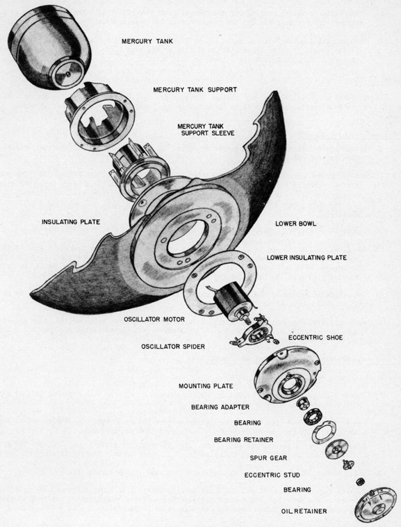
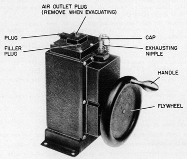
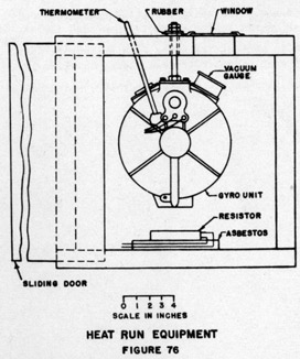 (7) When the wheel is stopped by reversing the motor leads, the motor windings rise to a high temperature. This usually results in a falling of the vacuum. If the gauge indication does not go below 28 inches and rises at least to 29 inches when the unit cools to room temperature, the unit is satisfactory and may be placed in service if it has passed the heat run.