36-1. Foreword.Shoring is the process of placing props against the side of a structure, or beneath or above anything, to prevent sinking or sagging.
During and after battle, ships may have occasion to support ruptured decks, to strengthen weakened bulkheads, to build up temporary bulkheads against the sea, to support hatches and doors, and to provide props for equipment that has broken loose. This is done largely by shoring.
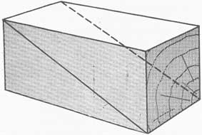
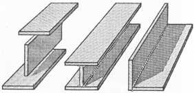
A shore is a portable beam. A wedge is a block, triangular on the sides and rectangular on the butt end. A shole is a flat plate which may be placed under the end of a shore to distribute weight or pressure. A strongback is a bar or beam, often shorter than a shore, and used to distribute pressure or to serve as an anchor for a patch over a hole. Any of the foregoing items can be made of metal or of wood.
In addition to shores, wedges, sholes, and strong-backs, the following tools, materials and equipment are often used in connection with shoring:
36-2. Wooden shores. The best woods available for shores are Douglas fir and yellow pine. Hemlock and spruce may be used but they are weaker, and hence less satisfactory. The wood should be straight-grained
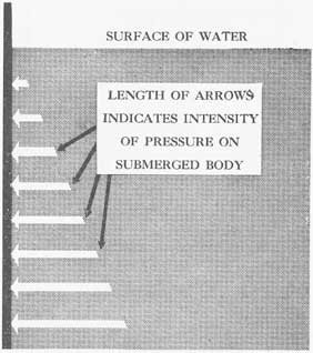
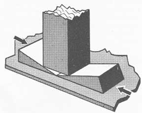
Figure 36-2. Diagram to illustrate increase in pressure with increase in depth.
and relatively free from knots and cracks. Green timbers have less strength than cured timbers. If it is necessary to use weaker woods, or those containing defects, more or heavier shores will be required to carry the same load. Hardwood shores are much stronger, but they are difficult to cut or to nail, and would not be very satisfactory for Naval work even if they were available. If possible, have shores treated with a fire-resisting chemical. The process takes about two weeks in a Navy yard. A fire-resisting paint may be applied to untreated shores, but never ordinary paint.
The length of a shore in use should never be over thirty times its minimum thickness. Thus, a 4-inch x 4-inch shore can be ten feet long, a 6-inch x 6-inch shore fifteen feet long, and a 4-inch x 6-inch shore ten feet long. If the proportion of length to thickness is greater than thirty to one, the shore will buckle
and may break. The shorter the shore in relation to its thickness, the greater the weight it will support. It would be safer, therefore, to keep well within limits and use a shore only twenty-four times as long as its minimum thickness.
However, it may be advisable to leave some shores in commercial lengths (16-18 feet), for they probably will have to be cut to fit anyway. Cutting shores in advance to fit various compartments is bad practice. Structural distortion will change the original dimensions of the compartments and may render the pre-cut shores useless.
Figure 36-3.
Figure 36-4.
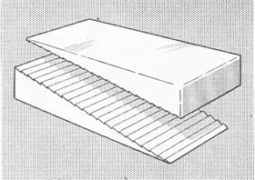
36-3. Wedges. Wedges should be made of soft wood, preferably Douglas fir or yellow pine. They should be cut with a coarse saw, and left rough and unpainted. An unpainted wedge will absorb water and grip better. While hardwood wedges have been used in commercial work and to some extent in Naval damage-control work, they have a bad tendency to become loose and must be watched carefully. A few hardwood wedges may be kept on hand, for they have good resistance to crushing.
284
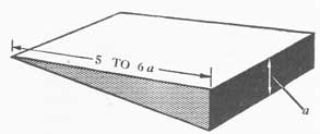
Wedges should be approximately as wide as the shores with which they are to he used. They may be made with various angles at the leading edge, but blunt wedges do not hold well; sharp wedges are preferable. A good wedge has a length of about six times its thickness. Thus, a wedge for use with 4-inch x 4-inch shores might be 4 inches wide, 2 inches thick and 12 inches long.
Figure 36-5.
36-4. Wooden sholes and strongbacks. Sholes may be made of yellow pine or Douglas fir planks, one inch or more in thickness and from eight to twelve inches wide. Wider sholes can be made by nailing cleats across two or more widths of planking. Even single planks may have to be cleated at the ends to prevent splitting. It is neither necessary nor desirable to make up sholes in advance, because prefabricated sholes might not fit where it is desired to use them.
A strongback may be all or part of an ordinary shore. Therefore, scraps of shores obtained when cutting the original shores or when holding drills in shoring may be retained for use as strongbacks and short shores. Shorter scraps may be cut up for wedges. Heavy planks are often used as strongbacks.
36-5. Metal shoring materials.Metal shoring materials have not proved to be satisfactory for making immediate repairs. The collapsible or telescopic shore consists of two sections of heavy duty iron pipe, one sliding closely within the other. Holes are drilled every three or four inches along the outer pipe, and possibly four holes along the inner pipe. Pins are provided, so that the length of the shore can be adjusted, and the sections can be held in place by several pins. A hinged shoe is often fitted to each end of the combined shore so that it can be fitted readily to any angle of inclination. Such shores are not very rigid, and the drilled holes weaken them; therefore,
they are not recommended. Single lengths of pipe are stronger, and they can be given resistance to kinking and collapsing by filling them with concrete.
Steel wedges may be more valuable for prying things apart than for actual shoring. However, they may be used in conjunction with wooden wedges to take some of the wear and pressure off the latter. They can also be welded in place when making semi-permanent repairs.
Figure 36-6.
Steel plate sholes are better than wooden sholes under the ends of iron pipe temporary stanchions, for pipe will cut through a wooden shole.
Steel bars, angle irons, and pipe can be used for strongbacks. Note must be taken of their tendency to spring back and forth under variable loads. These materials can also be used for making semi-permanent repairs when more time is available, provided that the necessary tools are at hand.
285
36-6. Obtaining and storing shoring materials. BuShips allowance lists designate the quantities and sizes of shoring materials that may be carried on ships of various types. Shores in excess of the allowance constitute an unnecessary fire and splinter hazard, even though chemically treated. Damage-control shores should be plainly marked, and their use for purposes
Figure 36-7.
Figure 36-8.
Figure 36-9.
other than repairing damage never should be permitted.
When in port it is advisable to obtain scrap lumber for conducting shoring drills. Such material, however, should be removed from the ship before leaving port.
When stowing shores, spread them well over the ship in accessible compartments on the deck next above the waterline and in boiler rooms and engine rooms. The pockets between frames and girders are good places to stow shores. Secure them with lines or metal clips so that they cannot break loose hut so that they can be removed easily when required. Wooden wedges should be made up into compact blocks secured with wooden battens nailed on the sides. Plugs may be kept in canvas bags securely tied to a beam or a stanchion.
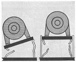
Figure 36-10. A simple and strong shoring structure.
Figure 36-11. A simple but weak shoring structure. Not recommended.
286
36-7. Rigging gear. Various kinds of rigging gear such as chainfalls, wire hawsers, blocks and tackle, and manila line will be found useful during shoring operations, especially for purposes of clearing away wreckage and restoring equipment to its original position. To a limited extent this gear may be used to hold equipment in position, but all lines have a tendency to stretch under stress and they are not rigid, so they cannot be relied upon to do the work of shores. Rigging of this nature has no compressive strength. When hooking up such gear, make sure that the fixed end is secured to a strong undamaged structure, or more damage may be created with consequent injury to personnel.
Figure 36-12. Shoring to avoid machinery obstructions.
Figure 36-13. Triangular shoring; a much stronger structure than that shown in figure 36-11.
36-8. Miscellaneous items. The allowance list will include a large number of miscellaneous items to be carried in repair lockers such as nails, sheet rubber, sheet packing, binding wire, bolts and nuts, etc. Small
items may be stowed in canvas bags to reduce their menace as splinter hazards. The bags should be stenciled to indicate their contents. All of these materials must be protected against rusting or rotting.
Ordinarily 8-penny, 12-penny, and 20-penny nails will prove to be adequate. Ships having wooden decks should carry some 60-penny nails cut to half length for securing plate patches to decks. On small vessels, ten pounds each of the smaller nails mentioned above will be sufficient for each repair locker. On larger vessels, divide one keg of each size between the repair parties.
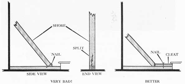
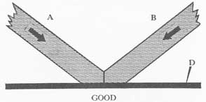
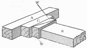
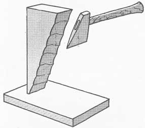
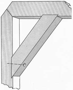
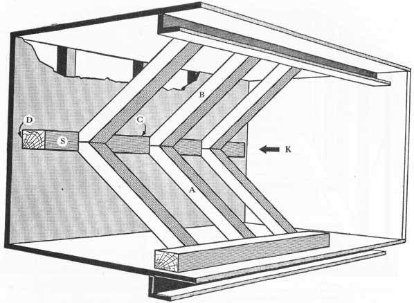
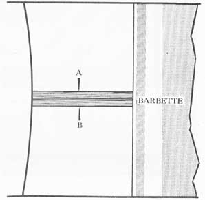
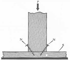
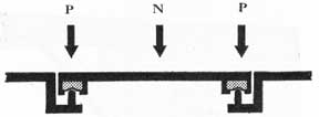
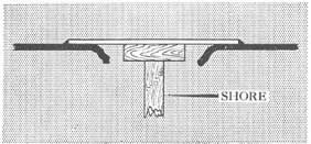
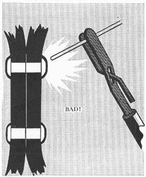
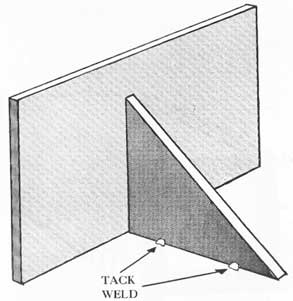
Nails are used to secure battens and cleats on shoring structures to reduce the possibilities of jumping and slipping. They also are used to hold members of a shoring structure in place temporarily, before making final adjustments. Generally, there is a tendency to use nails where they do little good; they actually may do harm by splitting shores or wedges (see fig. 36-1).
A few assorted bolts, nuts and washers may be carried in repair lockers. Blank flanges and flanged couplings should have bolts, nuts and washers secured in the flange holes so that they will be ready for immediate use.
Figure 36-14. Bracing to prevent bowing of shores.
PRESSURES ON FLOODED BULKHEADS
36-9. Water pressures on bulkheads. The pressure on a bulkhead or deck of a flooded compartment depends upon various factors including the following:
1. The depth of flooding.
2. The flooded area.
3. Whether there is any additional pressure caused by the ship's motion.
4. Whether or not the compartment is open to the sea.
Unless a watertight bulkhead has been weakened by corrosion or by an explosion, it may be expected to
287
withstand any static pressure that is likely to be put on it as a result of flooding.
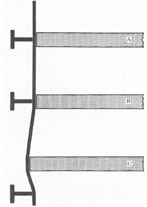
The water pressure at any point on a submerged bulkhead is the weight of the column of water over it. The pressure is therefore directly proportional to the height of the water column (see fig. 36-2), and for that reason watertight bulkheads on Naval vessels are built progressively stronger as they approach the ship's bottom.
Figure 36-15. Strength members locked in place by auxiliary shores.
Figure 36-16. Improvised measuring batten.
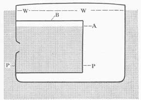
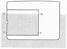
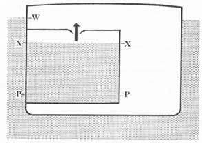
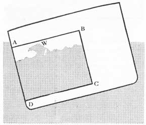
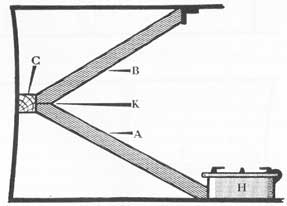
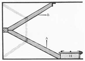
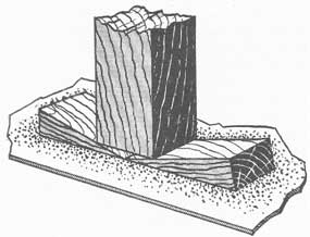
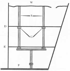
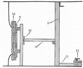
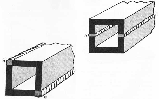
The depth of water in a compartment open to the sea and completely flooded is measured from the ocean surface not from the overhead. Thus, in figure 36-3, the pressure on point P is the weight of the column W-P. Even if the lower compartment is not entirely flooded but contains a layer of entrapped air at the top, the air will be compressed until it assumes the same pressure as the water column. The upward pressure against point B (fig. 36-3) is W-A, where A is the water level in the compartment. The same rule applies when the ocean level is below the level of the
overhead. In figure 36-4, the pressure on joint P is W-P.
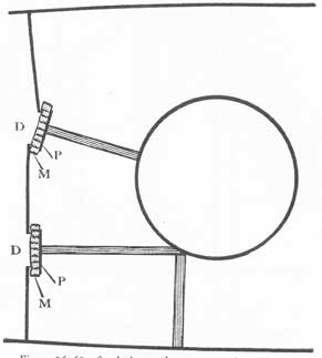
There is one case in which the above rule does not apply. Assume that the outside water level is at W, and the inside level at X as shown in figure 36-5. Water is coming into the compartment through a relatively slow leak, and the compartment is open enough at the top so that air can escape faster than water comes in. In this case, the pressure inside the compartment at P is X-P. This type of flooding is often encountered in spaces surrounding compartments that have borne the brunt of an explosion and have been opened wide to the sea.
Sea water weighs approximately 64 pounds per cubic foot. Therefore, the pressure over one square inch at a depth of one foot is.444 pounds. At nine feet it is 3.996 pounds per square inch. At 20 feet it is 8.88 pounds per square inch. The pressure at any point is equal in all directions, whether downward toward a deck or horizontally toward a bulkhead. The formulas for calculating the total pressure on a bulkhead are of little use in action. However, a bulkhead 20 feet wide and flooded to a depth of five feet would have a total load of 16,000 pounds on it. A bulkhead eight feet high and 20 feet wide, and flooded to a depth of 15 feet over the deck would have a total load of 112,640 pounds on it. These figures give some idea of the force that must be contained.
Figure 36-17. Diagram to illustrate a method of cutting shores.
288
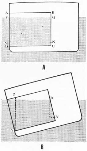
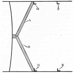
If the vessel remained entirely motionless in all three planes, the pressure at any given point would remain constant and the problem of shoring would be relatively simple. A light shoring structure might suffice; in fact, shoring might be altogether unnecessary. Consider, for example, a compartment A B C D, partially flooded (fig. 36-6). With the ship on even keel and trim, the pressure on point X is Y-X, and on N it is M-N. If the ship lists or rolls to port as indicated, the pressure on X will rise to Z-X, and that on N will decrease to R-N.
Figure 36-18.
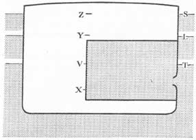
Or take the case of a compartment that is entirely flooded as shown in figure 36-7, with the ocean surface at L. The pressure on point X is Y-X. If the ocean surface rises to S and then drops to T because of high waves or plunging, the pressure head on point X will rise to Z-X and then drop to V-X.
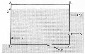
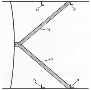
An example of similar effects is shown in the case of compartment A B C D (fig. 36-8) ruptured at N and P. If the compartment is partially full and the ship stationary, the pressure on point X is Z-X. However, if the ship moves ahead in direction M, ruptures N and P will scoop up water, even raising the level in the compartment above that of the ocean outside. Rupture P shows plate torn out and downward to form a dangerous scoop. The water will tend to back up against bulkhead A D, raising the level of Z and increasing pressure Z-X.
If a ship rolled or pitched slowly, or had no free surface, the effect of rolling and pitching would be simple variations of pressure as shown in figure 36-6. However, if the water has a chance to run rapidly, as shown in figure 36-9, it will have the same effect as a wave, and will pound heavily on A-D, momentarily increasing the pressure.
A variation from conditions shown in figure 36-8 occurs when a ship has its bow blown off. Then an athwartship bulkhead has to serve as a temporary bow. This bulkhead will receive varying pressures caused by wind and sea and by plunging effects.
It is not expected or desired that calculations of bulkhead pressures be made after a ship is hit. However, the foregoing remarks exemplify several important points:
Figure 36-19.
Figure 36-20.
Figure 36-21.
1. Intact bulkheads usually require no shoring.
2. The total load on a bulkhead of a flooded compartment is tremendous.
3. The pressure is greatest along the deck and least along the overhead.
4. The pressure depends upon the height of water over a given spot.
5. The pressure depends upon how the ship is rolling and pitching.
6. The pressure may depend upon how much headway the ship is making.
Since 3,4, and 5 are variable it is obvious that the pressure and stress will be variable. When undertaking any shoring operation, allow for the maximum stress which will be ample provision for safety. A
289
damaged bulkhead exposed to dynamic sea pressure always requires shoring.
A bulkhead and its supporting frames make up a sort of spring. It is obvious, therefore, that a bulkhead will bulge and pant as the pressure varies, and it will weave as the ship itself changes shape while working in a seaway. Hence, the pressure on shoring will increase and decrease, and the bulkhead will tend to "walk away" from the shores. Therefore, no shoring job can be considered completed until all of the slack has been taken up, and when the job is done a man must he left to watch it and to tighten up the wedges as they start to work loose. It should be borne
Figure 36-22. This type of notching is not good practice where heavy pressure is expected.
Figure 36-23.
in mind that shoring is intended to support; it is not intended to push warped bulkheads back to their original positions or shapes. Excessive shoring pressures may cause a bulkhead to collapse or rupture, especially at boundaries.
SHORING
36-10. When and where to shore. There is no
strict rule for determining whether or not to shore a deck or a bulkhead. Mere depth of water and consequent pressure is no criterion. A lower bulkhead will have more pressure upon it, but it will also have more
Figure 36-24. Beveling to produce a strong shoring job.
strength built into it. Also, a bulkhead may be weakened by corrosion, or the force of an explosion may loosen rivets, crack beams, shear plates, part seams, and otherwise weaken the structure. The only rules to follow are those dictated by good judgment after inspecting the damaged area. Deep bulges in plating, badly bowed frames and stanchions, loose rivets, cracks in seams, and panting of bulkheads are indications that shoring is needed.
There is a tendency to shore decks and bulkheads when it is not necessary. Just because water has replaced oil in a fuel-oil tank is no reason to suppose that the tank bulkheads need shoring. However, if there is visible evidence of weakening, always shore. The need for shoring patches and loose machinery is too obvious to require discussion. However, weakened supports under guns and machinery units may not be so obvious; they should be inspected carefully and properly shored to insure that further operation will not cause them to break loose.
When a compartment is flooded, the deck and all bulkheads around it are subject to pressure, and possibly even the overhead. Therefore, all containing structure may have to be shored, with priority given to the weakest bulkhead subject to the greatest
290
pressure. Bear in mind that the deck of a flooded upper compartment may have to be shored from beneath.
A plan should be prepared before action for shoring each major bulkhead, having due consideration to such impediments as boilers, pumps, pipe lines, lockers, stores, and sheathing. Know where the nearest supply of shores is located, and how to get them to the desired point with the least interruption of watertight integrity. Insofar as possible, stow stores away from sides and bulkheads to allow ready access for shoring and patching.
Figure 36-25. Example of an unsatisfactory shoring arrangement.
36-11. The strength of shores. The load which a shore can safely support depends upon several factors, as follows:
1. The material of which the shore is made-the stronger the material, the greater the load it will support.
2. The length between supports-the greater the length, the less the load that can be supported.
3. The minimum thickness of the shore-the greater the minimum thickness, the greater the load that can be supported.
4. The direction in which the pressure is applied in relation to the axis or grain of the shore.
Items 1 and 3 are determined by the allowance list; items 2 and 4 are determined by the shoring plan and by the obstacles that impede shoring attempts. Item 3 may require some explanation. While cross-section area has some bearing upon the strength of a shore, minimum thickness is far more important.
Thus, a 2-inch x 4-inch shore is much stronger than a 1-inch x 8-inch plank of the same length.
Thicker shores are sometimes made by nailing two timbers together; e.g., two 2-inch x 4-inch timbers to get a 4-inch x 4-inch shore. This composite shore is not as strong as an integral 4-inch x 4-inch piece of lumber.
When considering the strength of shores, we are concerned with the shore in two states only:
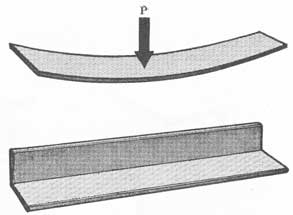
1. When it is in direct compression; that is, when the pressure is acting parallel to its axis. A column supporting the roof over a porch is an example of a shore in direct compression.
2. When it is subject to pressure acting perpendicular to its axis. A plank used as a foot bridge over a creek is an example of this.
Figure 36-26. The foot of this shore will crush under pressure and cannot be wedged.
Shores will support far more weight in direct compression than they will in cross-axial direction. It makes no difference whether the shores are placed horizontally or vertically; it does make a great difference how the pressure is applied in relation to their axes. Therefore, in designing a shoring structure; have as few shores as possible under cross-axial stress, and as many as possible under direct compression.
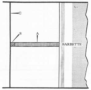
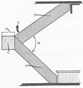
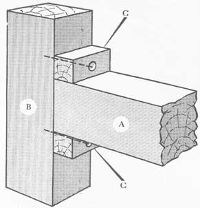
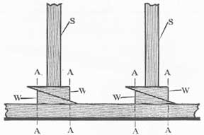
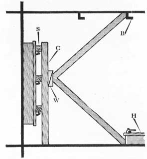
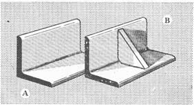
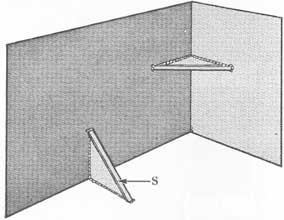
36-12. Basic shoring structures. The simplest and strongest shoring structure is illustrated in figure 36-10, where shore A, in direct compression, is anchored against the barbette and holds strongback S against bulkhead C.
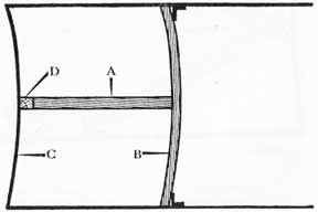
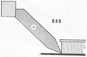
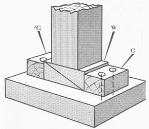
In figure 36-11 shore A is in direct compression, holding strongback D against bulkhead C. In this position, shore A will have its greatest resistance to breaking. Unfortunately, shore B is in its weakest position, as it is under cross-axial pressure. The whole structure is no stronger than its weakest member, and therefore this method is unsatisfactory.
291
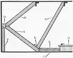
The foregoing method, however, is sometimes used temporarily to get support on a weak bulkhead as rapidly as possible, or under conditions where only moderate pressure is required to hold a patch in place over a shell hole. If, because of interferences F shown in figure 36-12, it becomes necessary to erect a shoring structure along such lines, additional strength may be afforded by installing such as members as Y and Z. Horizontal shores generally have to be supported by cleats or auxiliary shores K. Note that shore B is braced against a unit of machinery by means of T.
Figure 36-27. Sketch to show taper of a properly cut wedge.
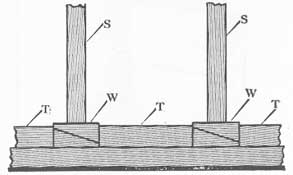
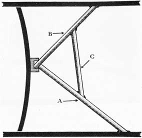
The usual method of installing shores is by a triangulation system such as that indicated in figure 36-13. Shores A and B are in direct compression, and their net effect is a resistance in direction K. If shore A alone is used, it will merely be leaning against C and will have no value whatever. Therefore, 13 must be installed. This method produces a much stronger job than the one illustrated in figure 36-11.
If it becomes necessary to employ relatively long shores because of a lack of strong supports close to the weakened bulkheads, and each shore is required to support an unusually heavy pressure, the timbers may have a tendency to bow. This tendency can be resisted and greater strength given to the shores if additional supporting shores are installed along the dotted lines shown in figure 36-14. Similar supports must also be installed to prevent lateral bowing. Instead of taking up on wedges until such a dangerous condition obtains, it is far better to install several shores similar to A and B.
If a shore in direct compression begins to bow, look out. It may snap in two at any moment. Do not expect a shore to support a weight beyond its safe working load. It is better to use too many shores than not enough.
The strength members of a shoring job, A B CD in figure 36-15, may have to be locked in place with auxiliary shores E and F to keep them from jumping out as the ship works. Nails may be used to secure members together. Note cleats K holding E in place.
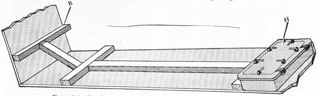
36-13. Measuring, cutting, and trimming shores. When measuring the length to which a shore must be cut (that is, the distance from a bulkhead to a nearby girder) a folding rule, a zig-zag rule, a steel tape, or a wooden batten may be used. Cotton line is very unsatisfactory because it is too elastic and therefore will give incorrect dimensions. The folding rule is too short for most work.
Figure 36-28. Wedges should be protected by a block of wood when being driven.
An efficient measuring batten can be made by securing two eight foot pieces of 11/2 inch x 11/2 inch lumber together with sliding clamps, as indicated in figure 36-16. Each clamp is secured to one leg only, so that the batten can be extended to a length of about fourteen feet. A locking device such as a screw would be desirable to hold the pieces in place once a measurement has been taken. However, a nail driven in lightly will do as well. When the batten has been extended to the necessary length to measure the gap, lock it. Then lay the batten along a shore, and mark and cut the timber to the proper length. This is more accurate and reliable than measuring in feet and inches, because men make many mistakes in measuring even when not under stress.
In general, shores should be cut 3/4 inch to 1 inch shorter than the gap they are to fill. The space thus provided allows room for wedges to enter. Remember that a shore should never be longer than thirty times its minimum thickness.
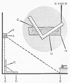
A carpenter's square may be used to measure the length of a shore to fit A-B (see fig. 36-17). Measure A-E and B-E in feet, and lay off those dimensions in inches on the square (C-E and D-E). Then C-D in inches is the length of A-B in feet. By laying the square along the shore as indicated, you can cut the required butt angle as B-Q-M. Note that allowance must be made for trimming the butt end.
Shores may be cut with an ordinary hand saw. All men in repair parties should be taught to use a saw.
292
properly (that is, not to press the blade down), or the saw will bind, thus delaying the job. This is especially true if the timber is wet. Some large ships which carry 6-inch x 6-inch or even 8-inch x 8-inch
Figure 36-29. Wedges should be driven from both sides simultaneously.
Figure 36-30. Use sand under wedges when the deck is slippery.
Figure 36-31. Filler piece C is used to partially take up space between A and B.
shores have lumberjacks' crosscut saws about five feet long. These saws will save a great deal of time in
cutting heavy timbers. Chisels, axes and hatchets are also used in cutting and trimming shores. All cutting tools should be kept sharp and free from rust.
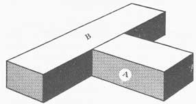
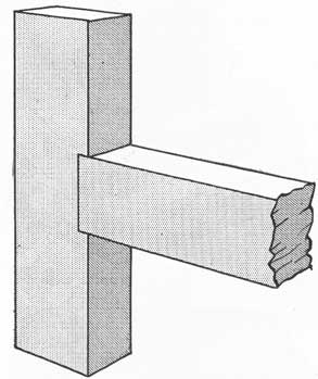
Trimming is the process of shaping the ends or sides of shoring timbers so that they will fit into the shoring structure. There are certain rules which must be observed in trimming or the shore will split or chip and thus become useless. For example, if shore A in figure 36-18 is to fit against a plane surface of shore B and is to take the load in direct compression, the end of A should be cut square and perpendicular to the axis of A. This will spread the pressure over the greatest possible area.
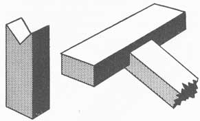
A sharp point should never be left on the end of a shore when the point will be required to take any pressure (fig. 36-19A). If it is, the point will chip and curl, thus permitting the shore to move and to work loose. The shore should be trimmed as in figure 36-19B, in order to present a substantial flat area at each surface of pressure.
Figure 36-32. Batten used to hold a filler piece in position.
Figure 36-33. Wedges should look like this when driven home.
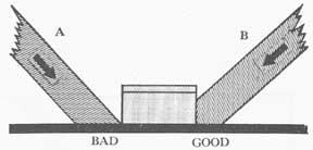
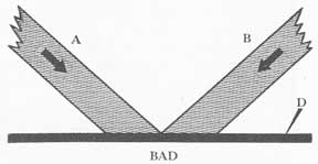
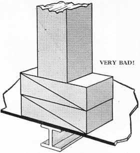
Figures 36-20 and 36-21 indicate two shores, A and B, pressing down on deck D. The method shown in 36-20 is very bad; that shown in figure 36-21 is good.
293
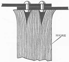
Shores are sometimes notched to fit against other shores (fig. 36-22). If there is any working of the shoring structure, the notched shore is very likely to split; hence this method should never be used when any great pressure is expected.
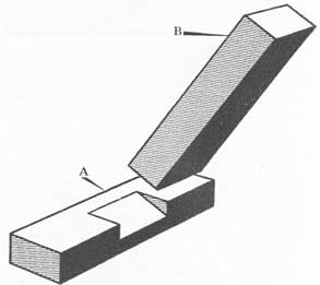
A safer and more satisfactory method is to cut a socket in the horizontal shore (see A of fig. 36-23) into which the butt of the inclined shore B will fit. The cutting can be done with a hand saw and a chisel, or with a hatchet.
It may be necessary to shape both ends of a shore to avoid weakening any part of the assembly. In figure 36-24 shores A and B have been shaped not only to
Figure 36-34. One method of cutting a wedge.
Figure 36-35. Cleats C are used to prevent A from sliding along B.
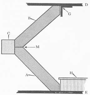
present flat surfaces to girder G and hatch H but also against decks D and E. They are also shaped at their other ends to present flat surfaces to each other and to strongback C at point M. This method makes for a strong shoring job. The flat surfaces are necessary where wedges are to be driven.
Figure 36-36. Cleats C are used to prevent wedges from backing out.
Figure 36-37. Notching to hold a brace in position.
The arrangement shown in figure 36-25 is unsatisfactory because if shore B is not perpendicular to A,
294
B will have a strong tendency to slip out. In this case angle θ is less than ninety degrees, and the shore will slip in direction T unless a block D is nailed on top of C. In the case illustrated, it would be far better to use a wide timber as a strongback, embodying D and C as one piece, because the pressure of B will
Figure 36-38. Notching to hold members in place.
Figure 36-39. Do not use more than one pair of wedges under one end of a shore.
tend to pry a nailed D away from C. A 2-inch x 10-inch plank could be used in place of C and D.
When trimming shores, take care to get the angles approximately correct, or you will have a weak structure, such as that shown in figure 36-26. The sharp nose at the base will crumple, which will shorten A and permit it to work loose.
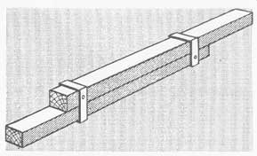
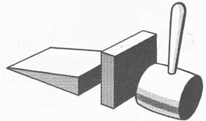
36-14. Wedges and cleats. A wedge should be cut with a coarse saw, and left rough and unpainted. An example is shown in figure 36-27. When driving a wedge, put a block of wood between the butt of the wedge and your maul, as shown in figure 36-28, to keep the wedge from splitting.
When using wedges to support a shore, either horizontally or vertically, always use two wedges driven simultaneously and evenly from both sides (see figure 36-29). This is to prevent tilting the shore. If there is not room enough to swing a second maul, the same effect is obtainable by holding a maul against the butt of one wedge and driving on the other.
If the deck is slippery, as when covered with fuel oil, throw sand under the wedges to reduce slipping (see fig. 36-30).
Figure 36-40. Strongbacks to distribute pressure over a bulkhead.
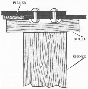
If wedges W (fig. 36-31) are not enough to take up all the space between shores A and B, use block C as a filler piece, provided that the joint is laid on and supported by a deck. It is bad practice to use
295
Figure 36-41. Use of several shores to distribute pressure along a strongback.
Figure 36-42. Use of extension members to carry pressure from shoring to point of support.
such filler pieces in vertical shoring, for the unsupported joint may collapse when the ship works. A batten (see P in fig. 36-32) nailed to each side will serve to support the structure.
Wedges are made by sawing a rectangular block as indicated in figure 36-33. When setting up wedges before driving, place them hypotenuse to hypotenuse; that is, so that they will look like the pair in figure 36-33 when driven home.
Makeshift wedges can readily be made by cutting a short piece of shore with a hatchet. Cut downward on to a block of wood as shown in figure 36-34.
A horizontal shoring member A may be supported temporarily by cleats C nailed to vertical shore B, as shown in figure 36-3 5. There is a danger that the cleats will split when nailed. Cleats C (see fig. 36-36) may also be nailed behind the butts of wedges W, to keep them from slipping.
296
Figure 36-43. Shoring structure to distribute pressure over the area being supported, and the area furnishing the support. Only part of the shoring structure on B is shown.
Members of a shoring structure may be tied together and supported by cutting shallow notches (1/4 inch plus) in one member, and fitting the other member into the socket. This weakens the cut member slightly, but it prevents slipping (see figs. 36-37 and 36-38). Nails may also be used for this purpose, with or without the notches, provided there is no great pressure on the nails. Remember, however, that nails may split shores.
It is very bad practice to use more than one pair of wedges behind one end of a shore as has been done in figure 36-39. The joint may collapse.
FUNDAMENTAL RULES FOR APPLYING SHORING
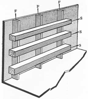
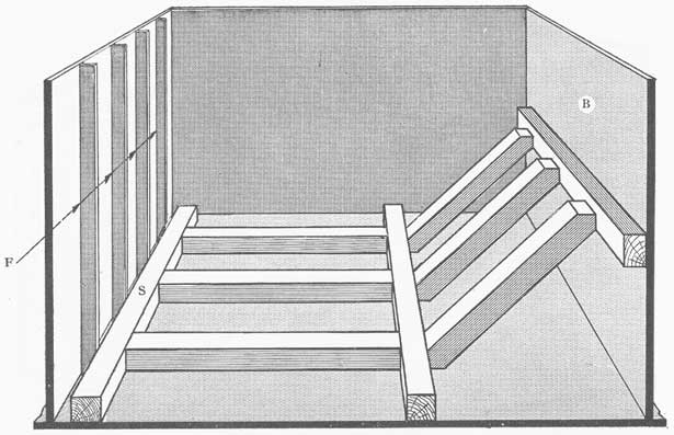
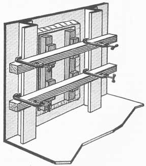
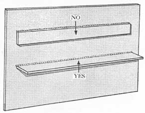
36-15. Shoring principles.The pressure on a bulkhead (or deck) must be taken up over a wide area, and not all at one or two points. Figure 36-40 shows a bulkhead in a small compartment. Pressure on the back of the bulkhead is absorbed by three parallel horizontal strongbacks, S, extending across all three stiffeners, F. If shores were installed directly upon and perpendicular to the bulkhead, without strongbacks interposed, pressure would be so concentrated at local
points that the bulkhead would be warped badly, thereby creating a dangerous condition. It is best to have a strongback covering the point of maximum bulge.
Each horizontal strongback must be backed up by a number of shores exerting a pressure perpendicular to the bulkhead as shown in figure 36-41: Notice that the resultant of supporting forces is in direction K. If only shores A and B were used, there would be insufficient pressure to support the bulkhead. Strong-back S would exert maximum pressure at point C, and practically none at D. This is because the bulkhead is bowed and because the strongback tends to curl outward from the point of pressure.
The butt ends of shores must be secured against undamaged strength members of the ship's structure. Hatches, stanchions, machinery foundations, frames, girders, armored decks and special clips may be used as anchorages. It may even be necessary to build a rather complicated structure to reach from a bulkhead to a safe support. Figure 36-42 indicates part of such a structure between strongback B and hatch H.
297
The pressure on a shoring structure may have to be spread over several supports, in order not to overstrain any one of them. In figure 36-43, a compound shoring structure props a bulkhead at B. The pressure is
Figure 36-44. Sketch to show effect of concentrated pressure on unsupported plating. Place shores at A and B-not at C.
absorbed by spreading it over several frames F on another bulkhead by means of strongback S. Note that when F is on a bulkhead rather than the shell of a ship, it is called a bulkhead stiffener.
When butting shores against bulkhead or decks, always place them opposite deck beams, frames or stiffeners, as at A and B (fig. 36-44), and never at unstrengthened points, as at C. Failure to observe this rule will result in warped bulkheads or decks, and possibly in ruptures. Sholes or strongbacks may be used to widen pressure areas.
If the pressure on a deck or bulkhead is so great that the next deck or bulkhead (used as an anchorage) cannot safely absorb all the pressure, it will be necessary to carry the shoring along to the next deck or bulkhead, or even farther. For example, weight W in figure 36-45 is 150 units. Each shore and each lower deck can support 100 units. By using two shores
at S, ample shoring strength is provided. However, as deck D can absorb only 100 units, it is necessary to carry the shoring down to deck E, adjusting wedges to divide the load, with a factor of safety at all points.
Figure 36-45. Shoring structure to distribute pressure among several decks. The header at F is used to straddle machinery.
Figure 36-46. Backing up a shoring job to provide added safety.
In figure 36-45 part of the load has been carried down to deck F.
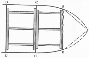
If it has been found necessary to shore to one bulkhead and there is any danger that the latter will carry away, the shoring must be carried to the next inboard bulkhead as soon as possible. Figure 36-46 represents a ship with its bow blown off. Bulkhead B-B becomes in effect the new bow, which must be shored. Because there will be extraordinary and varying pressure on B-B, it is desirable to shore C-C as a safety measure.
It is possible that a shoring structure will exert to
298
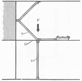
much pressure at one point, in which case it will be necessary to provide auxiliary support to prevent local failure. In figure 36-47, shore S is exerting a heavy pressure, P, on deck D. Shore T is installed as a
Figure 36-47. Downward pressure on the deck at D necessitates installation of shore T.
Figure 36-48. Shores A and B exert no pressure at right angles to their length.
safety measure. Note the use of sholes to spread pressure. This type of reinforcing may have to be done from above, as well as from below.
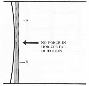
Shores must form a considerable angle with the bulkhead they are supporting. In figure 36-48 the two vertical shores are parallel to the bulkhead and exert
no pressure on it. In figure 36-49, the shores are perpendicular to the bulkhead and exert maximum pressure on it. The larger the angle (up to 90°), the greater the effectiveness. Therefore, it is better to anchor shores at P and R as in figure 36-51 than at M and N as in figure 36-50.
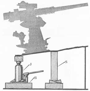
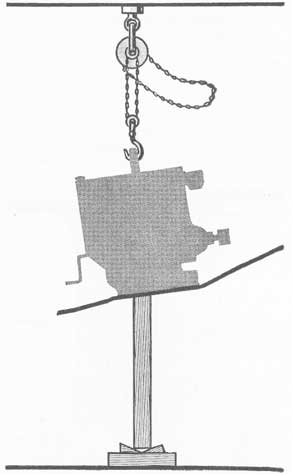
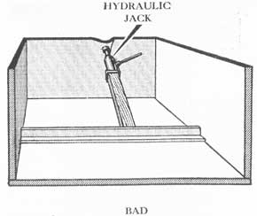
A screw jack (or a hydraulic jack), J in figure36-52, may be used to push heavy weights back to their original positions. Carry shoring S along with the jack, so that if the jack is suddenly knocked out
Figure 36-49. Shores A and B exert maximum pressure when placed at right angles to the weakened bulkhead.
Figure 36-50. If the slope of the shores is steep they exert more pressure to spread the decks than to support the bulkhead.
299
of place the weight will not crash. A wide block B may be placed under the base of the jack as it moves up. Chainfalls, or blocks and tackle, may be used to
Figure 36-51. Carrying shores well back makes them more effective in holding the bulkhead.
Figure 36-52. Jack and shoring being used to lift the gun back in position.
pull heavy weights back into position, as shown in figure 36-53. Follow along with shoring from beneath, as indicated, because the hoisting gear may break. The chainfall must be secured to a stout padeye, beam, or strongback.
Wooden or steel strongbacks may be laid over bomb holes or open hatches in order to secure the hook of
a chainfall or other hoisting tackle. If one timber is not strong enough, use several tied together. The ends
Figure 36-53. Use of chainfall and shoring to lift a heavy weight back in position.
Figure 36-54. It is bad practice to attempt reduction of a bulge in a bulkhead as shown here.
300
of the strongback must protrude well over the edges of the opening. If the weight is loose and free to move check its motion with steadying lines.
Damaged bulkheads often take a permanent set, which is somewhat independent of the bulge or panting caused by water pressure. Do not yield to the temptation to remove this permanent set by using jacks as shown in figure 36-54, or even by shoring. You will only crack the plate or loosen the boundaries.
36-16. Miscellaneous suggestions. Figure 36-55 shows what will happen if you anchor the end of a shore against a joint with rivet heads protruding. The shore will split. Interpose a shole, with pockets
Figure 36-55. Butt of a shore split by pressure against rivet heads.
Figure 36-56. Proper arrangement to prevent splitting the end of a shore against sharp projections.
chiseled out for the rivet heads as shown in figure 36-56.
Figure 36-57 illustrates an acceptable use of nails to lock shoring members together. The shore is
Figure 36-57. Use of nails to prevent side-slipping of a shore.
Figure 36-58. Trim wedges along lines A-A.
Figure 36-59. Install blocks T to prevent wedges from backing out.
pressing downward on strongback S. There will be very little lateral stress on the nails.
Figures 36-58 and 36-59 illustrate a method of locking wedges. After the wedges W have been driven
301
home, as shown in figure 36-58, cut them off along the lines A-A. Then cut blocks of two-by-four, T, to fit the gaps, and tap them in snugly as shown in figure 36-59.
Shoring frequently is used to hold patches in place over holes or cracks. In figure 36-60 three hammocks H are held in place by mess table T, strongbacks S, a cross-piece C, and by shores A and B. Note how C extends to the deck for vertical support.
Figure 36-60. Shoring a patch in place.
Figure 36-61. A mattress and mess table patch shored against a large hole.
In figure 36-61 two crew mattresses, M, are nailed to a mess table, T, and are held in place by a simple shoring structure. If any great pressure is expected
Figure 36-62. Steel plate and mattress patches shored against doorways.
Figure 36-63A. Shoring a hatch down; plan view.
on the patch B may have to be much larger in cross section than A. is. Note how the protruding edges of the hole dig into the mattress. Note also the means used to secure support. Patches of this type may be used to replace a defective hatch or door.
Figure 36-62 is a plan view of shoring used on a cruiser that has its bow blown off at frame 20. Doors D were blown completely away. Innerspring mattresses, M, backed by ten-pound (1/4-inch) steel plate, P, were laid over the holes and were held in place by
302
Figure 36-63B. Shoring a hatch down; end view of figure 36-63A.
Figure 36-64. Shoring a damaged door against its frame.
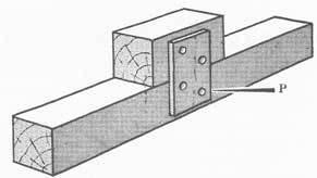
shores anchored against a barbette. Note the support provided for shoring on the port door. Angle clips were used to hold the starboard shoring. This job kept water from flooding aft on the main deck. Doors and hatches present similar problems in shoring. The basic rule is to put as many points of pressure on the closure as it has dogs.
Doors and hatches may be complicated by scuttles and quick-acting handwheels R (fig. 36-63A), in
Figure 36-65. Pressure points in shoring a flush hatch.
Figure 36-66.
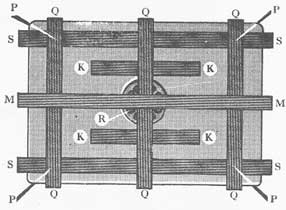
which case it is necessary to build up a framework of shores to clear the wheel. In figures 36-63A and 36-63B two strongbacks, S are laid lengthwise of the hatch near the knife edges and extending about two inches beyond the ends of the hatch. Cross-pieces Q are laid over the strongbacks. Filler blocks K, shown cut away, are placed under the cross-pieces to keep the hatch from buckling. One or more strongbacks, M, are laid across the cross-pieces, and shore A and wedges W are used to hold the structure against beam B.
If heavy pressure is expected under the hatch, it would be well to lay down two top strongbacks and to erect several vertical shores similar to those indicated
303
Figure 36-67. Diagram of a shoring job that was used on a battleship.
by the dotted lines (fig. 36-63B), pressing on points P.
Figure 36-64 indicates a door with ordinary dogs. Note how advantage has been taken of the dogs to obtain vertical support for strongbacks S, and of the deck to obtain support for cross-piece C. If a hatch or door is badly warped or bent it may be more satisfactory to erect a false closure; that is, a large patch.
Flush hatches should be shored with the pressure over the gaskets, as at P in figure 36-65, and not in the middle, as at N.
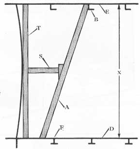
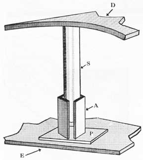
Figure 36-66 illustrates a form of shoring often used in long compartments having no stout anchorage available on the deck. Vertical shore A is cut considerably longer than dimension X, and when one end of A is secured to deck beam B, pressure transmitted through shore S forces A tight against deck D, the latter serving as an anchorage. This method of shoring has several defects: (1) shore A is under cross-axial stress, its weakest position; (2) if decks D and E are heaving, shore A will tend to jump and slip and may even crack; and the lower end of A may have to rest on a weak part of deck D and not over deck beam F. To overcome these defects, shoring must be done in depth; that is, a series of supporting shores must be installed to take some of the strain off A.
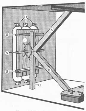
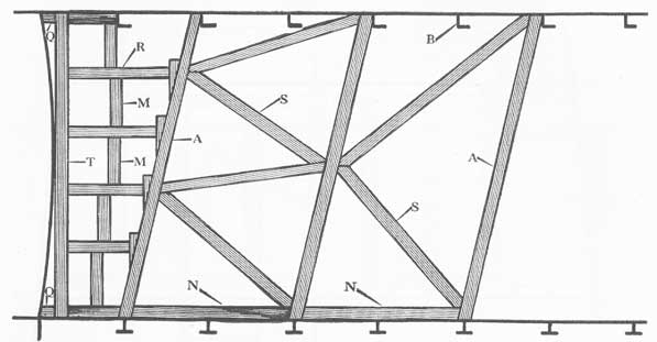
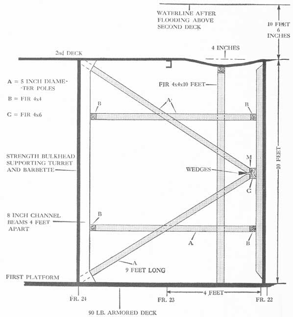
Figure 36-67 shows how slanting timbers A may be used to support shores S, which in turn hold vertical strongback T against a weakened bulkhead. Wedges are used where their need is indicated, although the members can often be cut accurately enough to
eliminate considerable wedging. Thus, shores R can be cut a bit long and they will serve as their own wedges as they are driven home. Remember to take up the slack as the bulkhead pants, to prevent cracking of seams. Equalize the strain on all members. Note the horizontal members N used to divide the load at the bases, blocks Q used to support the boundaries, and
Figure 36-68. Use of strongbacks and C-clamps to wedge a patch in position.
304
Figure 36-69. Plan view of shoring; heavy cruiser with bow blown off at frame 20.
spacers M used for auxiliary support. This method was employed in a magazine on a battleship.
Figure 36-68 illustrate a compact shoring job used to hold a patch over a hole or crack in the ship's hull plating. In one case, when a welded port insert cracked so badly as to admit a considerable amount of water, a sheet of rubber packing backed by boards was held in place by horizontal shores and wedges. A pillow or a mattress may be used instead of the sheet rubber packing, depending upon circumstances.
Adjustable screw clamps will be found valuable in making temporary repairs in action.
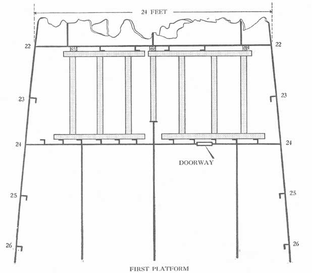
The job shown in figures 36-69 and 36-70 proved to be highly successful, for the ship subsequently was able to steam a considerable distance to an advanced
base. It would have been advisable to shore the bulkhead at frame 24 as a safety measure in case the forward bulkhead gave away. The wedging shown in figure 36-70 is definitely bad, because the wedges tend to force the shores out of place. The wedges should have been driven from top and bottom in the slot marked M.
Figure 36-71 illustrates a shoring job done on a cruiser when storms distorted the forecastle deck D. Stanchions K were badly bent and weakened. Note the use of strongbacks M and N to spread the load. Shores S were in axial compression, their strongest position. Main deck E was given additional support. Battens B (nailed) were used to tie the members together. This job involved many of the principles previously described.
305
Figure 36-70. Profile view of shoring, heavy cruiser with bow blown off at frame 20.
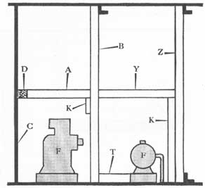
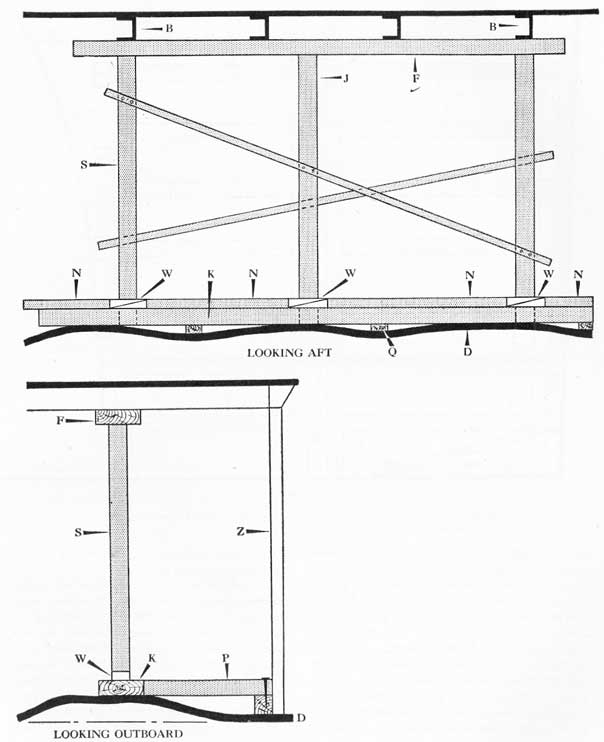
Figure 36-72 shows a job done on a major vessel when an explosion warped and weakened deck D. A strongback, K, was laid on the deck, and another, F, was laid across deck beams B. Pressure was absorbed by shores S and wedges W. The wedges were locked in place with blocks N. Note how strongback K was prevented from slipping sideways by means of P. On a corrugated bulkhead or deck it may be necessary to
use blocks or shims, Q, to secure a good distribution of pressures. Z is a frame or a bulkhead stiffener.
The use of F across beams B was advisable, not only to provide an upper support for J, but also to keep the upper ends of the other shores from slipping. Nails and battens were also used.
Figures 36-73A and 36-73B illustrate a shoring job done on a cruiser when heavy storms ruptured shell
306
Figure 36-71. Shoring to support a distorted forecastle deck on a cruiser.
307
Figure 36-72. Shoring to hold down a weakened deck over a flooded compartment.
308
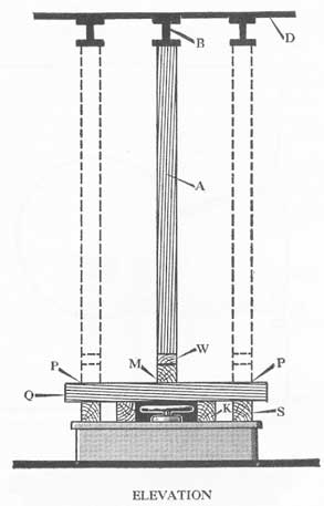
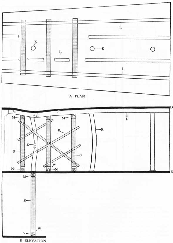
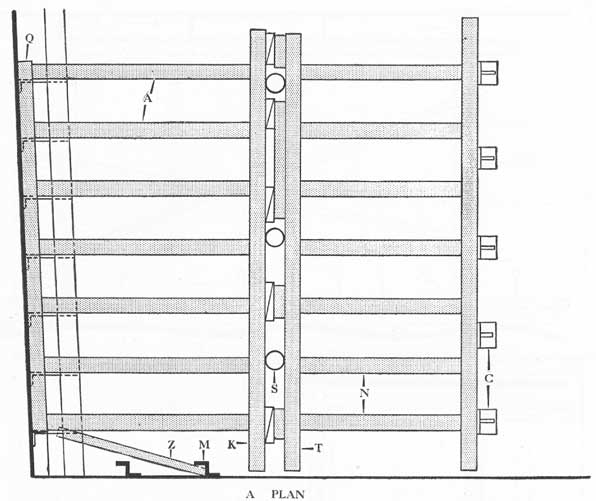
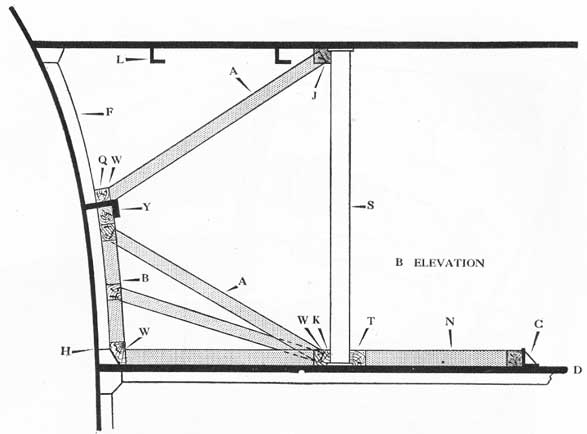
Figure 36-73A. Plan view of shoring to support ruptured frames in the bow of a cruiser.
plating adjacent to frame 12 and sheared off seven consecutive frames along a line indicated by H. A riveted seam also began to open. Sea water entered and gradually rose to a height of thirty inches over deck D. Strongbacks J and K were placed along a row of stanchions, S, for support. J was held in place temporarily with adjustable clamps. Horizontal strongbacks, such as Q, were placed along the damaged hull plating, and shores A were erected to hold them in place. Wedging points are indicated by W. The butt ends of shores A fitted into sockets chamfered into the strongbacks. No notches were cut in the ends of any of the shores. The stanchions and the whole structure were reinforced by strongback T, shores N and angle clips C. The latter were welded to deck D. Note blocks B used to provide vertical support for bulkhead strongbacks, and how longitudinal frame
Y was utilized to give support. Bulkhead stiffener M was also used to anchor brace Z.
The operation was impeded by stores and floating gear which had to be cleared away. Three submersible electric pumps were used. When the shell plating was securely held, all cracks were calked with rags and oakum, after which the compartment was pumped dry. Upon completion of this operation the ship operated for three weeks before receiving any additional repairs. This job is an excellent example of good shoring practice. While it may appear to involve a great deal of careful wood fitting and joining, none of the work is beyond the capacity of the average high school student who has had a year's course in manual training. The job was completed in three hours.
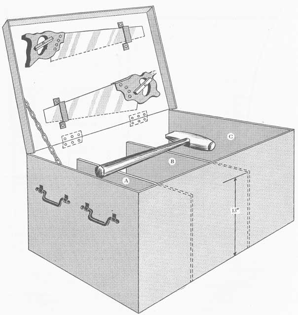
36-17. A shoring chest. The chest shown in figure 36-74 is divided into three compartments, as follows:
309
Figure 36-73B. Elevation of shoring job shown in figure 36-73A.
1. Compartment A contains wedges.
2. Compartment C contains 2-inch x 4-inch and 4-inch x 4-inch wooden blocks about 12 inches long.
3. Compartment B contains:
2 claw hammers.
1 hatchet.
8 adjustable clamps (6 in. and 8 in.).
1 sledge (10 lbs.).
5 pounds of oakum.
1 sounding rod.
1 zig-zag rule.
1 steel tape (75 ft.).
1 spike maul.
15 pounds of nails (30 penny).
10 pounds of nails (20 penny).
1 battery lantern.
If there is room, include a five-pound bag of sand. Note the carpenter's crosscut saws secured to the lid. Preferably, the weight of the loaded chest should be limited to what two men can carry under the handicaps imposed by access and damage.
It is suggested that one such chest be stowed at each below-deck repair station. Two to four men should be detailed to carry the chest to the vicinity of damage. Having the chest available eliminates loss of time in sending men back for gear that has been forgotten.
THE USE OF STEEL SHAPES IN SHORING OPERATIONS
36-18. Advantages and disadvantages of using steel shapes. Steel has several advantages for use in shoring operations:
1. It is fireproof.
2. It is much stronger than wood.
3. It saves room, because a less complicated shoring structure is required.
4. Welded members will not slide or jump out.
5. Repairs can be semi-permanent in nature, thus often permitting a ship to continue in operation whereas dependence upon wooden shores would not make this possible.
6. Many types of repairs that cannot be made with wooden shores can be made with welded steel.
310
Figure 36-74. A shoring chest for transporting tools, wedges, and blocks to the scene of the damage. It is made of 16-gauge sheet metal; dimensions are designed to suit the smallest opening through which the chest must be passed to reach the damaged area.
The disadvantage of steel is that it generally requires the use of special tools operated by air, electricity, or gunpowder. The danger of using any spark-or flame-producing equipment in making repairs cannot be stressed too strongly, especially in the case of aircraft carriers where explosive gases may be present.
Personnel of vessels having only one welding
machine should not look forward to making many action repairs involving welding, because the first shell hit may knock out the necessary apparatus. Vessels having welding equipment should train several men in cutting and welding. Advantage must be taken of opportunities to have men trained in the welding schools now operating at Navy yards, at the Destroyer Base in
311
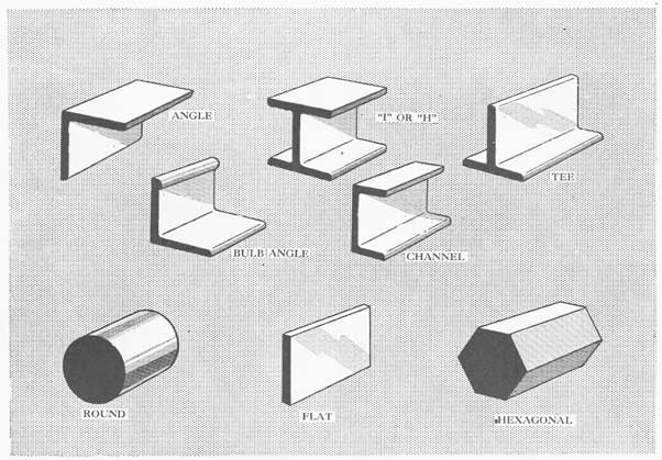
Figure 36-75. Some of the shapes commonly carried aboard ship.
Figure 36-76.
San Diego, and at various other places. A poor welder can create more damage than he can correct. Classes should be held in the use of velocity-power tools, stressing absolute adherence to the manufacturer's instructions in order to avoid breaking the tools and injuring personnel.
36-19. Shoring with steel shapes. In general, the rules for installing wooden shores apply also in the case of steel shores. The principles are the same; only the methods of implementing them differ.
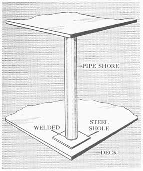
Figure 36-77. Pipe used as a vertical shore.
312
Figure 36-78. Steel wedges.
Figure 36-79. Angle clips; B with bracket.
Figure 36-80. Steel plate welded over a hole in the deck.
Figure 36-81. Stiffener welded on to reinforce plate.
Figure 36-82. Angle iron has high resistance to spring or bending.
Figure 36-83. Shapes made by welding flat bar stock together.
Figure 36-84. Welding flat bar stock on the back of a plate patch.
The shapes generally used in shoring and repair operations are flat plate, bar stock, pipe, various types of angle irons, wedges, and sliding (telescopic) shores. The thickness of steel plate is measured by its weight per square foot; that is, five pound plate is 1/8-inch thick and ten pound plate is 1/4-inch thick. Some of the more common steel shapes are illustrated in figure 36-75.
313
Metal shapes may be cut with hacksaws, pneumatic chisels, electric welding tools and oxyacetylene torches. The last-named process is the most rapid. Any spark-or flame-producing cutter may cause the explosion of combustible gases. Aircraft-carrier personnel must be especially vigilant with respect to this point. Any of the above-mentioned gear can be used in clearing away wreckage.
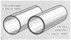
Pipe is either ordinary (light walled) or heavy duty
Figure 36-85. Strengthening the edges of a bulkhead by welding in plate.
(thick walled), as shown in figure 36-76. Steel pipe shores (see fig. 36-77) are much stronger than wooden shores. Another important feature is that they can be welded in place, which eliminates a great deal of extra bracing. However, they require careful cutting and fitting, and much more time is involved in the
Figure 36-87. System of shoring involving steel pipe welded in place.
Figure 36-86. Angle irons and channel irons welded together form rigid shores.
314
complete operation than would be the case if wood were used.
Steel wedges, as shown in figure 36-78, may be used to force a shore against a bulkhead, after which
Figure 36-88. Side plates welded in place to restore foundation.
Figure 36-89. Repair of a pulled out stanchion. Angle irons A are welded to the stanchion and the deck.
the wedges may be welded in place. Steel wedges are sometimes milled out lightly to form locking teeth, as indicated. An angle clip is a short piece of angle iron such as A in figure 36-79. It can be made much stronger by welding in bracket B. Angle clips are used to anchor the ends of shores. They can be
welded to decks or bulkheads at strong points, or they can be secured by means of a velocity-power tool. Make up some of these angle clips in advance, and stow them in repair lockers.
Flat plate may be welded over a bomb or shell hole as shown in figure 36-80. It may be necessary to shore
Figure 36-90. Do not try to weld leaky riveted seams.
Figure 36-91. Tack weld used to hold shoring members temporarily.
315
up the center of the patch temporarily, as shown. Later, stiffeners can be welded in place, and a strong-back welded across below if necessary.
Large steel plates intended to patch decks or bulkheads subject to pressure may need to be reinforced with strips of angle iron welded on the back. The latter are known as "stiffeners" (see fig. 36-81).
Flat bar stock has little resistance to spring or bending when the pressure is applied across the narrow dimension, as at P in figure 36-82. Angle iron has high resistance to spring or bending. Angle iron may be made by welding flat bar stock together as shown in figure 36-83. This, however, is a slow process.
When welding flat bar stock on the back of a plate patch, do it as shown in the lower portion of figure 36-84.
The edges of a bulkhead can be strengthened by welding in triangular pieces of steel plate as indicated in figure 36-85. To install the brace in a hurry, weld in a rectangular piece of plate and then cut off the upper triangle. Further strength can be given by welding a flat strip along the edge of the bracket, as at S in figure 36-85, to act as a face plate. Two angle irons or channel irons may be welded together as at A and B in figure 36-86 to form a rigid shore. A single angle iron tends to open up when subjected to direct compression or a bending force.
With welding and sufficient time available steel pipe shores can be secured to a deck or bulkhead where it is most convenient, having due regard for the strength under the anchorage. This may eliminate a great deal of intricate temporary shoring.
Shores A and B in figure 36-87 can be tied together with a rigid bar C welded in place. Note the use of channel iron as a strongback. It is equally necessary to weld a transverse brace to prevent side slipping and bending in the direction at right angles to the page.
Weakened or ruptured machinery foundations may be repaired by welding on side plates or angle irons after the unit has been pulled or jacked back to its original position as shown in figure 36-88. To do this, it may be necessary to unbolt or to cut the machine from its foundation. Use temporary wooden shores to support the unit while the operation is in progress.
Figure 36-89 shows how angle iron A can be used to restore a stanchion, S, that has been pulled out of deck E when deck D is blown upward. The angle irons are welded to both the stanchion and the deck. P is a patch over a hole. Never try to weld a leaky riveted
seam as shown in figure 36-90. The intense heat will only cause the leak to spread.
Steel shoring members may be held in place temporarily by tack welding as shown in figure 36-91. When ready to move the structure it is possible to cut the small welds with a pneumatic chisel, and later make strong welds.
To hold the face plate of a bulkhead stiffener up to its work, and to prevent its "laying-over" when it is on the bowed side of a bulged bulkhead, weld in small trapezoidal tripping brackets between the face plate and the bulkhead at three-foot intervals.
INSTRUCTION AND TRAINING IN SHORING
36-20. Shoring instructions. A large number of men, whether they are in repair parties or not, should be trained in the details of shoring operations. There has been a tendency to teach only the result; that is, men are given models of compartments and miniature shores, and are taught how shores have been applied to bulkheads under ideal conditions. But the details of the actual preparations and application are too often omitted. It is useless to teach the fine points of pressure vectors unless the man doing the job can use his tools to measure, cut, and trim shores, and to secure the shores in place.
Instruction might well begin with the use of hand tools: saws, hammers, hatchets, mauls, etc. For example, take a small piece of spare shoring timber and let men cut off short lengths. Many men will press down on the saw blade and cause it to bind. If such binding delays the job one-half minute at each cut, a complicated shoring job may be delayed thirty minutes or more, possibly with disastrous results.
Next, rig up a shore between a deck and a beam, and have the men practice driving wedges. Let them see why they must drive two wedges simultaneously from opposite sides to keep the shore from tilting, and why they must use a block buffer to avoid splitting the wedges. Illustrate the use of sand or sandpaper to reduce slipping on an oily deck. Teach men how to use battens, squares, rulers, and tapes in measuring the lengths of shores required for various jobs, and how to measure the angles to which the timbers must be trimmed in order to get a stout structure.
When men have mastered these simple details, demonstrate the principles of spreading pressure, how timbers are strong in direct compression and weak across the grain, why strong anchorages are necessary, and similar points. Blackboard talks and models may be
316
used for this instruction. Point out parts of the ship that can be used in shoring operations.
Then, by means of models, the instructor can begin to teach shoring structures. Begin with simple cases, and do not change the types of jobs faster than men can grasp them.
After a group has mastered about four types of structures, drive the lessons home with actual shoring drills. Shore a hatch, a door, or a bulkhead. The instructor should discuss the steps as he goes along. Ask questions to learn whether the men know why they are doing certain things. Point out complications, such as interferences from bunks and pipe lines, and difficulties in finding strong supports. For example, require the engineers to shore a bulkhead in a
machinery filled compartment. Have as many men as possible observing the work, and when the job is done bring other men into the compartment to observe and to discuss the result. At this point models can be used extensively. The man will now be able to visualize them better, and if the mockups (models) are stowed in accessible places, the men can work out interesting problems in their spare time.
Some ships go so far as to designate types of shoring structures by numbers or names, so that if the damage control officer sends word to a repair party to erect a shoring structure of type George, the men will know what to do. This system has merit but it must be borne in mind that variations in damage call for wide differences in actual shoring structures, even though the principles involved remain the same.