37-1. Foreword. With the aid of wood or steel cofferdams, concrete can often be used to advantage in stopping leaks to establish flooding boundaries, such as those involving ruptured bulkheads, damaged hatches, warped doors, leaky bounding bars, deck ruptures around pipe lines, shell or bomb holes in decks or hull plating, and leaky deck or bulkhead seams. To a limited extent, concrete may also be used to restore strength in damaged machinery supports.
The fundamental requirements for successful use of concrete include:
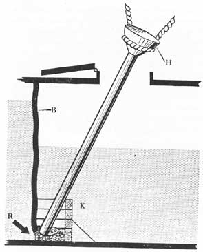
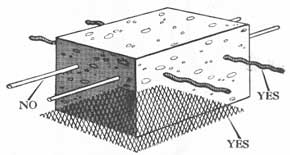
Figure 37-1. Bulkhead B is ruptured at R. A form (K) is built around the damaged area. Concrete poured into hopper H flows down and fills the form. It may be necessary to put wedges or pillows into rupture R to keep the concrete from working out through the hole or to restrict the flow of water which would wash out cement. Keep the end of the tube well down in the laid concrete, as if the rupture was small, and was being filled with tooth paste from a tube.
1. Suitable materials.
2. Accurate measurement of materials.
3. Thorough mixing.
4. A workable mix.
5. Proper application.
6. Prompt placing after mixing.
37-2. Materials needed. The materials which should be available on board ship for use in making concrete are coarse sand, high early strength Portland cement, calcium chloride, aggregate (gravel) and fresh water.
The gravel should not exceed one inch in maximum diameter, and about 30 per cent of its content should be small pebbles. It should be as rough as possible, crushed rock being an excellent aggregate. In an emergency, small pieces of hard coral or broken fire brick may be used. Aggregate serves as a reinforcing material, the larger pieces tending to hold the mass together even after cracking has occurred.
Although leaks have been stopped on Naval vessels with a mixture of cement and sand alone, aggregate must be incorporated if economy is a factor. Moreover, space and weight to carry cement are limited. In addition, aggregate tends to prevent leaking of the mix through cracks in the form or through fragment holes at the time that the mix is put in place.
The sand should be coarse, clear and sharp, and should be free from vegetable matter and oil. It should be a true sand-not powdered coral. It should be washed in fresh water before being stowed away.
Fresh water at or above 70° F. should be used. It should be clean and free from oil and vegetable matter. In an emergency, salt water may, be substituted. The amount of water should be just enough to make a sticky plastic mass that will hang together but can still be poured through a large tube. Too much water reduces the strength and watertightness of concrete, with the result that it is likely to wash away. About 5 1/2 gallons of water for each 100 pounds of cement will make a satisfactory concrete.
318
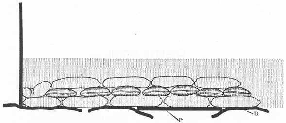
Figure 37-2. Sketch illustrating the use of bagged concrete to stop leaks in ruptured deck D. Note the use of steel plate P to support the bags, and how the bags are laid criss-cross.
The basic materials should be mixed in approximately the following proportions (by volume):
1 part
High early strength Portland cement.
1 1/2 parts
Sand.
2 parts
Aggregate.
Various authorities recommend different formulas, with slightly higher proportions of sand and aggregate. If more bulk is required less cement may be used. Four cubic feet of the separate materials will make about three cubic feet of concrete when mixed, although the concrete will tend to swell when deposited under water.
The materials may be mixed in gun tubs, in a wooden box, or on the deck of a washroom. In the latter case, cover drains to keep from fouling them. The best procedure is to lay the sand first, and to pour the cement over it. The two are mixed dry by turning them over with a shovel or a garden hoe until the mass has a uniform color. The aggregate is then added and the mixture again turned over.
Calcium chloride generates heat upon contact with water, and thereby facilitates the setting of concrete (under water). Use two pounds of calcium chloride for each 51/2 gallons of water, dissolving the calcium chloride in the water before the latter is poured into the dry ingredients. The use of calcium chloride is desirable but not mandatory. It tends to impart high early strength characteristics. However, it is more desirable to have a rather stiff mixture made with water above 70° F.
37-3. Application of concrete. Concrete should be deposited promptly after it is mixed. For a large job
it may be advisable to have two mixing boxes, staggering the batches so as to have a steady flow of fresh concrete.
In depositing concrete above water it usually is necessary to build a form to retain the concrete while it is setting. Frames, bulkheads and other parts of the ship's structure may be used as part of the form. Place the concrete in the form with a shovel or a bucket. Do not drop or throw the material in loosely, for this will tend to entrap air pockets. Press or tamp the concrete tightly into the form. If the concrete settles rapidly without air pockets it is a sign that it contains too much water. If time and conditions permit, it is advisable to scrape and clean metal surfaces against which concrete is to be deposited.
Concrete can best be deposited under water by use of a chute made of watertight pipe or waterproofed canvas. It may also be made of 1/2-inch lumber. The chute or tube should be large enough to permit free flow of the concrete. An inside diameter of four to six inches should suffice. The upper end, however, may be made much larger, to serve as a sort of hopper. The tube is used to avoid dropping the concrete loosely through the water and thereby wasting much of it. The lower end of the tube should be right down in the mass of deposited concrete. If possible, keep the tube full of concrete to exclude water, and lay the mixture like toothpaste flowing from a tube.
At best, it is difficult to use concrete for underwater leak stopping. The heavier materials will sink to the bottom, hut the finer particles tend to wash away-especially the cement. Therefore, every effort must be
319
made to prevent the flow of water through or across the mixture while it is being poured and after it is in place. As a preliminary measure, try to stop or restrict the flow of water through cracks or holes that are to be patched. Mattresses, pillows, oakum, wedges, plugs and similar materials may be used for this purpose.
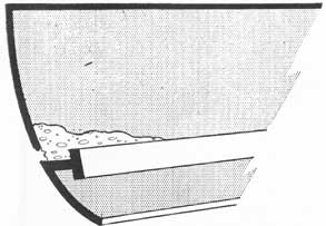
Figure 37-3. Advantage may sometimes be taken of the ship's stringers or framing to support concrete while it is setting.
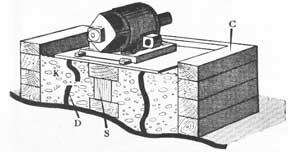
Figure 37-4. Diagram to illustrate bow concrete may be used to make a support for a machinery unit. C, form; S, shores; K, concrete; D, damaged support.
After the leaks have been restricted as much as possible, erect a form around the damaged area as shown in figure 37-1. Steel plates or lumber (preferably tongue and groove) may be used. The form itself should be tight and it should fit snugly against decks and bulkheads to reduce the washing effect of water. The form is necessarily left open at the top for deposition of the concrete.
Put the chute well down into the form, with the lower end practically buried in concrete. Fill the chute to a height above the water level, and move the chute along the bottom, gradually depositing concrete as you go. Continue to shovel concrete into the tube. Do not let the concrete pile up at any one point and then try to relocate it with a shovel or a hoe.
Often it has been found advisable to install a
temporary drain pipe running from a point near the leaky seam or hole to a point outside the form. The pipe carries away water while the concrete is setting, after which the pipe can be plugged.
Concrete may also be deposited under water by utilizing bags of about one cubic foot capacity (see fig. 37-2). The bags may be made of a coarse cloth such as burlap-the common gunny sack. After filling a bag about two-thirds full, tie it securely. The bags of concrete are laid in a criss-cross manner, so that the whole structure is interlocked. Cement leaking through the pores in the sacking will bind the bags together.
Bagged concrete can be used to great advantage in stopping deck ruptures in flooded compartments. It may be necessary to provide some support in the form of angle irons, steel plate, or timbers to keep the bags from falling through before the concrete sets. Concrete, however, will set faster and better in bags than in a form.
Figure 37-5. Smooth wire is practically useless for reinforcing concrete. Notched or jagged rods, or expanded metal should be used to give mechanical holding power in case the concrete fractures.
37-4. Setting time. The average initial setting time of most high early strength Portland cement under water at a temperature of 50° F. and in depths up to 15 feet, is between 30 and 45 minutes. However, the concrete will not have any appreciable strength until it has set for at least a day, maximum strength being attained when it is about four weeks old.
As previously noted, sea water may be used in mixing concrete when fresh water is not available. It speeds the initial set. In this connection it is important to remember that if a smaller amount of water is used the time of setting will be reduced. This practice, however, results in a stiffer mix which is more difficult to handle
37-5. Reinforcing concrete. Dry concrete has a had tendency to crack and fracture under stress, especially if the mixture does not contain enough cement.
320
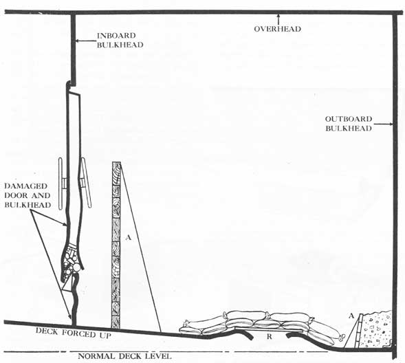
Figure 37-6. Leaks and ruptures in damaged door and bulkhead plugged with wood wedges and rags to stop flow prior to pumping. Two cofferdams (A) are being used to hold back water remaining in the compartment. The space between one cofferdam and the outboard bulkhead has been filled with concrete. To check flow of water prior to pumping, bags of concrete were laid over deck rupture R.
Unsupported, it may break away from the place where laid. It is therefore desirable to bury jagged metal rods or heavy wire mesh in the concrete as it is poured (see fig. 37-5). These reinforcing materials will hold the blocks of dry concrete together mechanically no matter where the fractures occur. Smooth rods
or wires are useless for this purpose. In addition, it is advisable to weld bolts, hooks or nails to the hull structure, and to have them protruding into the poured concrete in order to provide a positive mechanical bond between the ship and the patch. Ship's frames may also be utilized for this purpose.
321
CHAPTER XXXVIII
THE ENGINEER DEPARTMENT AND DAMAGE CONTROL
38-1. Foreword. The engineer department is an essential and integral part of the damage-control organization. The general functions of the engineer department in the control of damage are set forth in FTP-170B. They are as follows:
1. To operate and maintain the machinery and power facilities necessary to insure the maximum mobility and maneuverability of the ship.
2. To establish and maintain an uninterrupted supply of electrical power and compressed air to the offensive weapons and their auxiliaries.
3. By means of drainage pumps and connected piping, to pump out flooded compartments as directed by the damage control officer.
4. By transfer within the ship of fuel oil and fresh water, as directed by the damage control officer, to maintain the ship in stable condition.
5. To repair damage with a minimum of interference to 1 and 2 above.
38-2. Main responsibilities of engineer officer in battle. The main responsibilities of the engineer officer in battle may be outlined as follows:
1. To meet all the speed demands of the Commanding Officer.
2. To route live steam in the main and auxiliary steam lines to the main engines and all of their auxiliaries, and the auxiliary exhaust.
3. To route feed water and condensate in all systems.
4. To provide an adequate supply of fuel oil to all boilers (or main and auxiliary engines, in the case of Diesel-driven vessels) through the fuel-oil transfer and service systems.
5. To provide electrical power for the ship, especially for ship control and the gunnery department, through main- and emergency-power systems, with alternate supply feeders and the casualty power system.
6. To see that proper action is taken in the case of any minor casualties, such as hot bearings, low vacuum, and other derangements which
may prevent the engineering plant from meeting all speed demands.
7. To provide an adequate supply of compressed air for the gas-ejection system.
8. To supervise the engineering casualty control organization and make decisions relative to this vital phase of engineering in case of battle damage to any part of the plant.
9. To cooperate with the damage control officer:
a. In maintaining the stability of the ship by shifting fuel oil, pumping ballast, and flooding tanks.
b. By maintaining adequate pressure in the fire-main systems.
c. In the operation of a considerable portion of the drainage systems.
10. As a line head of department in the chain of command, to succeed to the command of the ship in case his seniors become casualties.
11. In accordance with recent alterations removing the ship-control apparatus from central station and making the main engine control station a ship-control station, the engineer officer must be prepared to take over steering control in case the other ship-control stations are disabled.
12. If the damage control officer and his principal assistant become casualties, the engineer officer must be prepared to take over control of damage. The necessity for this has already been amply demonstrated in the case of at least one of our heavy cruisers, where after a serious battle casualty had occurred the engineer officer took over control of damage and performed outstanding work in helping to save the ship.
38-3. Publications recommended for study. In order to perform his damage-control duties efficiently, the engineer officer must be thoroughly familiar with the following publications in addition to U. S. Navy Regulations and the Bureau of Ships Manual. Many of them contain mandatory directives relative to engineering damage control:
322
1. Ship's Damage Control Book.
2. Ship's Engineering Casualty Control Book.
3. FTP-170B.
4. USF-10A.
5. Type Commander's letters on damage control.
6. Bureau of Ships letters relative to damage control, engineering casualty control, etc.
7. Bureau of Ships bulletins of information.
A careful study of the action and war damage reports is also recommended, for they contain many valuable lessons in engineering damage control.
38-4. Factors in engineering damage control. Engineering Damage Control can be considered logically in two sections, as follows:
1. Limitation of damage.
2. Repair of damage.
LIMITATION OF DAMAGE
38-5. Relationship of design to damage control. Prevention of damage to engineering installations is largely a function of shipdesign and construction. The general arrangement of the machinery and electric plants, including piping and wiring systems, must provide for their location underneath and behind armor and the torpedo protection in large vessels. In small vessels where armor and torpedo protection are impracticable of installation, the design provides maximum dispersal of the engineering plant in as many watertight compartments as possible, with duplicate units and provision for split-plant operation wherever this may be done.
38-6. Personnel and organization. Matters pertaining to organization, training and education of personnel for damage control are discussed in other Chapters. As far as the engineer department is concerned, every officer and man of the organization should be so well trained and educated in the principles of damage control that, if the complement of the engineer's force is 456 officers and men, the engineer's repair party numbers 456 officers and men.
Since preventive damage control consists largely of correct utilization of the damage-control features built into the ship, the training of personnel must place emphasis on proper operation of the systems and equipment furnished, and their upkeep and maintenance.
The subject of fire fighting is dealt with in Chapter XXXII. All officers and men of the engineer force should be thoroughly familiar with the use of firefighting apparatus in the engineering spaces. In addition, it is desirable that all attend the fire-fighting
school. The engineer officer should cooperate with the damage control officer to see that all hands are trained in the proper method of extinguishing electrical fires.
Electrical equipment and wiring are to be found in nearly every compartment on the ship, and electrician's mates cannot always be present wherever an electrical fire starts. Too often valuable electrical apparatus has been ruined beyond economical repair by ignorant or careless fire fighting. All hands must be impressed with the simple fact that the only proper way to extinguish a purely electrical fire is through the use of carbon dioxide. Abundant past experience has indicated the necessity for this.
38-7. Split-plant operation.Limitation of damage is accomplished in the engineer department chiefly by proper segregation of the plant in split-plant operation. Split-plant operation may be defined as the subdivision of the entire machinery and electrical plant of the engineer department into two or more independent plants (depending on layout and design) by closing the proper valves and switches.
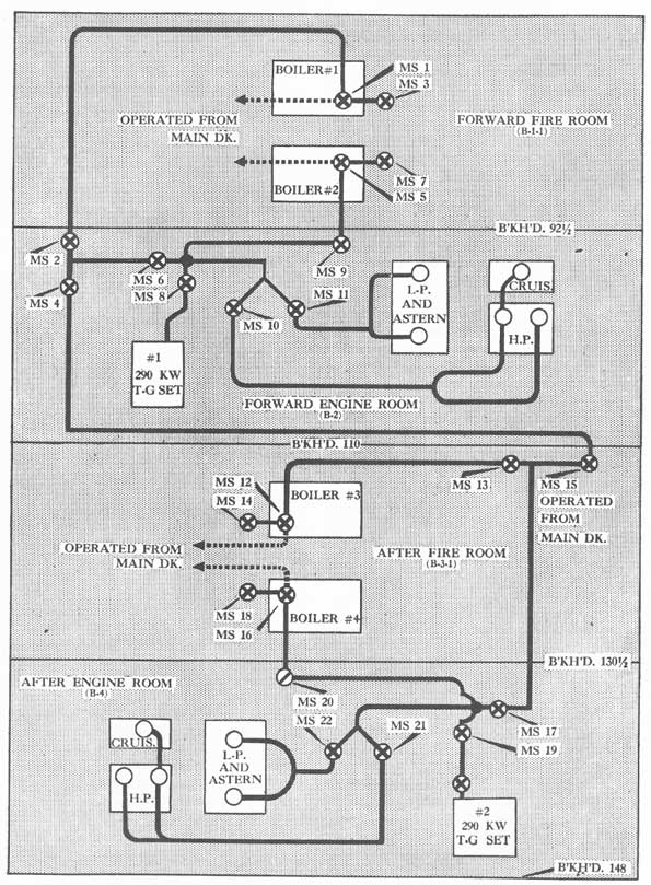
Taking a relatively new DD as an example and referring to figure 38-1, boilers 1 and 2 in the forward fireroom are supplying main steam to the starboard turbines, located in the forward engine room, and power to the starboard shaft. Boilers 3 and 4, located in the after fireroom, are supplying main steam to the port turbines, located in the after engine room, and power to the port shaft. The two main plants are isolated by closing two main stop valves in the forward engine room cross-over line, one located on the port side forward in the forward engine room, and the other on the starboard side near the forward bulkhead of the after fireroom. The by-pass valve is open around the forward engine room cross-over valve, and the drains are open in the cross-over line to the after fire-room, since 600 p.s.i. steam lines cannot be warmed up rapidly without danger of rupture from water hammer. The cross-over line is thus warmed and ready, in case the plant must be "unsplit." The forward engine room is the control engine room and the engineer officer's battle station. All the other essential systems are split, so that the plants are independent, for example:
1. Auxiliary steam. Steam to the auxiliaries in the forward fireroom and engine room is supplied by boilers 1 and 2, and to the auxiliaries in the after fireroom and engine room by boilers 3 and 4. Cut-out valves are closed isolating the two plants.
323
Figure 38-1. Main steam piping of a Fletcher class destroyer.
324
2. Auxiliary exhaust. Exhaust from the forward auxiliaries is utilized in the forward engine room in the main distilling plant, turbine gland seal and de-aerating feed tank; excess goes to the turbines and the main condenser. Cut-out valves are closed so that the exhaust from the after auxiliaries is similarly disposed of in the after engine room. The latest DD's have an auxiliary distilling plant in the after engine room.
3. Main feed and condensate. Cut-out valves are closed so that the two plants are isolated. Condensate from the forward main condenser goes to the forward de-aerating and feed tank in the forward engine room, then via two main feed pumps, located in the forward engine room, to boilers 1 and 2. Make-up feed is taken from two tanks, one on each side of the forward fire-room. Emergency feed is taken by a reciprocating feed pump located in the forward fireroom via a direct cold suction line from the two reserve feed tanks, one on each side of the fireroom, and discharged directly to boilers 1 and 2. This pump should be kept warmed up and turning over slowly in split-plant operation. A duplicate of this installation is located in the after engine room and fireroom.
4. H.P. and L.P. drains. The steam drain mains are isolated forward and aft by cut-out valves.
5. Fuel-oil system. Two fuel-oil service pumps in the forward fireroom take direct suction from service tanks located on the centerline forward of the forward fireroom with the cofferdam (A4VF or A5VF) in between, and discharge through a fuel-oil heater to the manifolds located on the fronts of boilers 1 and 2. This installation is duplicated in the after fireroom for boilers 3 and 4, and the after service tanks are located on the centerline just abaft the after engine room. Cut-out valves are closed in the fuel-oil transfer system, and the manifold, suction and sluice valves to the fuel-oil storage tanks are kept closed. No transfer of fuel oiI should be attempted in action unless directed by the damage control officer to correct list or trim.
6. Distilling plants. Latest DD's have a main distilling plant (12,000 G.P.D.) located in the forward engine room and an auxiliary distilling plant (4,000 G.P.D.) located in the after engine room. These plants are isolated from each other in split-plant operation, and are available for distillation of boiler feed in an emergency.
Unless reserve feed becomes dangerously low they should be kept secured in action, due to danger of priming and salting up. The reserve feed supply should be kept up in wartime cruising so that these plants can be kept secured in action.
In the newest destroyers, one 400 K.W. A.C. turbogenerator with a 50 K.W. D.C. exciter (also supplying D.C. power to searchlights, etc.) on the same shaft, is located in each engine room. Electric power is distributed from main distribution switchboards, one in each engine room. The A.C. and D.C. generators, although capable of parallel operation if desired, are not paralleled in split-plant operation. In general, the distribution of power is as follows: Units located above and forward of the forward engine room receive their power through "normal" feeders from the forward distribution board, and have "alternate" feeders from the after distribution board. Similarly, units aft receive "normal" power from the after distribution board, with "alternate" feeders from the forward distribution board. Main power cables are well distributed in runs on both sides of the ship, in oil-tight trunks where they pass through oil tanks, and the main lire-control wiring is led through a vertical wiring trunk centrally located 'all the way up to the main-battery director. Suitable connections are provided with "bus-tie" switches, so that the main distribution boards can be tied together for parallel operation, or one generator can supply both boards by closing the "bus-tie" switches. If the "bus-tie" switches are opened at either or both boards, each board is independent for split-plant operation. Normal practice in DD's is to close the "bus-tie" switch at the after board, and open the "bus-tie" switch at the forward board for split-plant operation. Since the forward engine room is the control engine room, the operator at the forward distribution board has control over splitting or unsplitting the electric plant. In addition to the main generators, one 100 K.W. emergency Diesel-driven generator is located in a separate compartment forward and another aft of the engineering spaces. Each Diesel generator has its own switchboard located in the same compartment, with suitable cable connections and "bus-tie" switches for tying the two Diesel switchboards together so that either emergency generator can energize both emergency boards (but they cannot be paralleled) , or separating them for split-plant operation. Also, either Diesel switchboard can supply the main distribution boards through suitable cable connections and "bus-tie" switches. Normally, in split-plant operation, all the "bus-ties" are open at
325
both Diesel boards, so that the forward Diesel can supply forward emergency power and the after Diesel after emergency power. The Diesel-driven generators are supplied with automatic electric starting (from storage battery supply) , and are designed to start automatically through a voltage relay when the main A.C. voltage falls to a certain specified value lower than the normal 450 volts, and to be up to speed and take over the emergency load in less than 10 seconds. Most emergency Diesel-driven generators will pass this test satisfactorily; however, it is recommended that automatic starting not be relied upon in action in cold weather, when the Diesels are slow in starting. When action is imminent in cold weather it is recommended that the Diesels be started and warmed up and preferably kept running during action, so that no delay will be encountered in obtaining emergency power. Also, when not in action, when entering or leaving port, or navigating in restricted waters, it will be found desirable to start the after Diesel generator and keep it running so that a reliable immediate supply of emergency steering power is available. In wartime cruising, a regular routine of starting and testing emergency Diesel generators should be established, and a thorough check made to insure that the starting batteries are kept properly charged. The necessity for these precautions is abundantly borne out by operating experience. The experienced practical engineer officer must always "have an ace up his sleeve" where automatic devices are concerned.
The vital services on the DD's have three sources of power, i.e., normal, alternate and emergency. Normal and alternate supplies come from the main generators, and emergency from the Diesel-driven generators. Transfer of power is accomplished by means of automatic or manual-type transfer switches located near the units involved throughout the ship. The vital services so supplied are:
1. All 5"/38 cal. and 40 mm. gun mounts.
2. Steering gear.
3. Radio control and emergency radio.
4. I.C. and F.C. switchboard.
5. Battle lighting.
6. Electrically driven fire pumps.
Note that electric auxiliaries in the engineer department are not vital, and are not supplied with emergency power. No direct current is available from either Diesel generator. A casualty power system, consisting of certain permanent and portable runs of cable is supplied for use in the event of damage to main power cables.
The destroyer has been used as the example of split-plant operation in the foregoing paragraphs because the DD installation is relatively simple. In the case of larger ships which have multiplex engineering plants and intricate watertight compartmentation split-plant operation is not so simple. The electric plants especially are more complicated, large ships having as many as four independent plants. In some of the later ships, Diesel-driven generators supply up to 40 per cent of the normal power supply and no emergency Diesels are installed. The same general principles apply, however, therefore no attempt will be made to give a detailed example here.
38-8. The Engineering Casualty Control Book. FTP-170B requires the engineer department of each ship to prepare an Engineering Casualty Control Book. Its purpose is to establish methods of operating the engineering plant under all conditions. In other words, this book should represent standard engineer department doctrine for operational casualties, battle casualties, and all conditions that have to be met in running the engineering plant.
The detailed instructions for preparing the Engineering Casualty Control Book are contained in FTP170B, Chapter 9. In general, this book must contain the following information:
1. Diagrams of all piping and wiring systems.
2. Instructions for setting valves and fittings of the main propelling machinery and auxiliaries under the several material conditions.
3. Instructions dealing with the division, segregation, and readiness of main and auxiliary sources of electrical light and power, the distribution thereof, and the setting of distribution controls (switches, etc.) under the several conditions of readiness.
4. Instructions regarding the securing and isolation of auxiliary machinery units which are not required to be in service under certain conditions of readiness.
5. Instructions concerning the stowage of fuel oil, indicating the full bunker condition, the order in which tanks shall be emptied, the order in which tanks shall be refilled and instructions for ballasting by filling specified tanks with sea water to compensate for oil consumed.
6. Instructions similar to the above but concerned with fresh-water systems.
7. A list of casualties that may occur in battle, with detailed instructions for dealing with them.
The several conditions of engineering readiness
326
referred to in No. 2 above may be described in general as follows:
1. All boilers and machinery ready for full power.
2. Sufficient boiler power for flank speed, based on Fleet speed as standard. Unnecessary boilers on one-hour notice. Aircraft carriers and screens as required for flight operations.
3. Same as 2, except that idle boilers are on six-hour notice. CV's and screen ships same as 2.
4. Boiler power for station keeping at Fleet speed; other boilers on six-hour notice.
The Engineering Casualty Control Book is supplementary in some particulars to the ship's Damage Control Book, which is used as a primary source of damage-control information and instructions by the engineer department as well as the other departments. Certain instructions and bills with diagrams are required to be in both the Damage Control Book and the Engineering Casualty Control Book. They are as follows:
1. Fuel-oil system-service, transfer and overflow.
2. Casualty power system with data and details on auxiliary sources of power, connections, and methods of distributing power.
3. Fire and flushing systems.
4. Drainage systems.
5. Compressed-air systems.
6. Magazine sprinkling systems.
7. Counterflooding bill,
8. Miscellaneous damage-control gear bill.
In addition to the bills, diagrams, and instructions above, the following systems shall be covered with instructions and diagrams:
1. Main steam line.
2. Auxiliary steam line.
3. Auxiliary exhaust line.
4. Main and auxiliary feed and condensate systems.
5. Electric plant generation, control, and supply of power to gun batteries, auxiliaries, radio, lighting, searchlights, and visual signalling equipment.
The Bureau of Ships has prepared the engineering casualty control plates and diagrams for some ships, and when this is the case duplicate plates are found in the ship's Damage Control Book. Ships which do not have diagrams furnished by the Bureau of Ships are required to prepare their own. The following diagrams, or engineering casualty control plates, are. furnished by the Bureau of Ships for new destroyers:
1. Plate EC I
-Main and auxiliary steam.
2. Plate EC II
-Auxiliary exhaust steam.
3. Plate EC III
-Main and auxiliary feed.
4. Plate EC IV
-Fuel-oil service.
5. Plate EC 101
-Bus-ties and steering gear; electrical wiring diagram.
6. Plate EC 102
-Casualty power supply system.
7. Plate EC 103
-Main battery supply system; electrical.
8. Plate EC 104
-Electrical wiring diagrams; lighting of 5-inch mounts, handling rooms and magazines, I.C. and plotting room, battle dressing stations, and Diesel generator rooms.
9. Plate EC 105
-Electrical wiring diagrams; lighting of engine rooms and firerooms, combat information center, radio central, coding room, chart house, transmitter rooms, and medical storeroom.
The above plates are isometric plans, showing the piping and wiring diagrams by decks, and the connections between decks. Larger vessels will require more E.C. Plates than DD's, particularly of the electrical systems, but the example given above indicates the important systems for the benefit of ships which have to prepare their own. It is recommended that ships preparing their own diagrams make them of the functional type, i.e., main battery power and antiaircraft battery power on separate diagrams, rather than all battle power on one plan. In dealing with electrical systems diagrams become unduly complicated and of little value in emergencies if too many systems are superimposed upon a single plan. The engineer officer may prepare as many diagrams as he desires, in addition to those furnished by the Bureau of Ships.
It is recommended that large plates of the important piping and wiring systems be posted at the engineering casualty control station and important operating stations. In this connection, many vessels have made up plates of Bakelite, masonite, lamicoid or other suitable materials, with pins, pegs, or other devices indicating the closing and opening of valves and switches. Personnel at these stations can thus see at a glance the up-to-the-minute status of any important system.
38-9. Example of Engineering Casualty Control Book-large ship. An Engineering Casualty Control
327
Book of a large vessel will serve as an example of the material content of a well-written casualty control book, and may be described as follows:
Part A-Organization for engineering casualty control.
This part contains a brief description of the general organization of the engineering department for casualty control, with a description of the plan for relieving the watch, and going to general quarters from a war cruising condition. This plan is not mandatory, but is comprehensive and well organized; therefore, it is quoted below for information and guidance. It can be adapted to small vessels as well as large ones:
"To eliminate confusion and to expedite the manning of battle stations at general quarters, the engineering section on watch shall remain on watch and be augmented from the relief sections to provide the necessary additional personnel to man stations not manned in cruising condition. The remaining men of the relief sections are assigned to Repair V, engineering reserve, and gunnery department battle stations. The cruising watch is based on a full three-section watch with sufficient stations manned to supply full power continuously. This system requires that each man have three distinct battle stations, the particular station manned being dependent on the watch section on watch at the time general quarters sounds. If general quarters or condition I-Easy lasts for an extended period, personnel will be shifted to relieve those men on the hottest stations and those stations requiring the greatest degree of alertness. In general, this shift will be made as follows:
1. For fireroom and engine room and generator crews, the general quarters crews comprise about one and one-half steaming sections, the remaining one and one half sections manning Repair V and other relatively cool or inactive stations. This permits a natural watch and watch to be set up for firerooms and engine rooms, the off time being spent at an easier station. These two groups will alternate with each other. It should be noted that this will normally result in the first relief section being split in two to augment the on watch and the second relief sections respectively.
2. For other divisions and stations where the ratio of additional personnel is much higher and conditions less onerous, the relief of men on alert watches will be accomplished by an organized shift of personnel to the stations they would have had if general quarters had been initiated during the new watch.
3. The shifts referred to above will be made at such time as best fits the tactical situation, and will fit the meal schedule if meals are not served on station. These reliefs will be made only on orders from main control.
4. The shift will be made in an orderly manner and reserve personnel from Repair V will be utilized to avoid leaving vital stations unmanned during the shift."
Part B-Engineering battle (and Repair V station) bill.
Detailed bill by stations, showing men by number and rate, and detailing general quarters and war cruising stations.
Part C-Repair V organization and remote valve control bill.
This contains the organization of Repair V, and the detailed list of valves, assignment to groups of personnel, etc., for remote-controlled valves in the engineer department.
Part D-Engineering casualty control conditions (plant isolation).
Detailed instructions for split-plant operation for engineering conditions corresponding to conditions of readiness for action I, I-E, II, and III.
Part E-Communications bill and voice procedure.
Description of telephone systems used by the engineer department in battle, how they are manned, and vocabulary and instructions for talkers.
Part F-De-energization of circuits in vicinity of gasoline system in case of damage.
Detailed instructions for pulling circuits, investigation of damage, etc., in the vicinity of gasoline tanks and adjacent spaces.
Part G-Fuel-oil bill, sequence of emptying fuel-oil tanks, and water ballasting.
Detailed instructions for operating the fuel-oil transfer, filling and water ballasting systems.
Part H-Operational instructions and data.
Detailed routine operating instructions and data concerning the engineering plant.
Part I-Sample casualties and corrective measures.
Includes both operational and battle casualties.
Part J-Excerpts from Damage Control Book-valve bills.
For valves operated by engineer department.
Part K-System Diagrams.
Those recommended in previous paragraphs and prescribed by FTP-170B.
For engineer officers of destroyers, destroyer escorts
328
and frigates, excellent Type Organization Books and Engineering Casualty Control Books are available, and are obtainable from the Fleet Operational Training Commands or Type Commanders. These are of great aid (particularly in the case of a new construction) in preparing the organization of the engineer department and the Engineering Casualty Control Book. The Type Casualty Control Books are outlines designed to serve as guides, and the details should be filled in by engineer officers for individual ships as prescribed by FTP-170B and described in the preceding paragraphs. Chips of other types (new construction) are advised to obtain organization books and casualty control books for guidance from vessels of their types already in commission.
38-10. Readiness of auxiliary machinery. All auxiliary machinery likely to be required in battle, or used to overcome the effects of damage must be ready for immediate use. Steam-driven machinery, such as drainage pumps and fuel-oil transfer pumps should be kept warmed up and drained, and periodically operated to insure readiness. Mention has been made in a previous paragraph of the necessity for testing emergency Diesel-driven generators. Similarly, other Diesel-driven equipment, such as emergency fire pumps, -divorced" generators, etc., should be tested periodically. Electrical units should be energized up to the starting panel. Instructions dealing with these items should be in the Engineering Casualty Control Book.
38-11. Isolation of open funnel drains. A recent action report emphasizes the necessity for proper isolation of open funnel drain systems. The principal flooding came from the open funnel drains. The pump drains in the after engine room of this installation were collected in a funnel drain tank which emptied through connecting piping into a collecting tank in the after fireroom. There was no bulkhead cut-out valve that could be operated from the fireroom. The foregoing account shows the importance of providing and utilizing properly the means for splitting and securing this system, as well as the more vital systems. The Engineering Casualty Control Book should contain the necessary instructions and precautions.
38-12. Securing unnecessary machinery and piping systems. Some machinery and equipment are unnecessary in battle, and should be secured to prevent leakage, flooding, or short circuits in the event of damage. (Refer to FTP-170B, Art. 9-13). Interruption of the services should be close to the sources of power or service in order to isolate the maximum lengths of
the lines. The Engineering Casualty Control Book should contain instructions covering the securing of the following items unless existing conditions require their use:
1. Steam and exhaust lines to galley, heating system, showers, washrooms, laundry, pantries, fuel-oil heating coils, lubricating oil settling tanks, soot blowers, sea chests, and evaporators. In this connection, consideration should be given to the securing of the exposed piping and drains to the whistle and siren in battle. A type, task force and Commanding Officer's policy should be ascertained by engineer officers of individual vessels. As an example of the desirability of securing this piping in action, some personnel on one ship were severely burned and scalded by steam escaping from a ruptured whistle line in the superstructure following a shell hit.
2. Air supply to workshops and compartment air-testing connections.
3. Electrical circuits to boat-handling equipment, trash burners, laundry, galley, bakery, battery-charging panels, and anchor windlass.
4. Tanks and lines supplying fuel to galleys, workshops and trash burners should be drained and the valves secured.
5. Close valves and isolate as much of the freshwater system as possible, especially to baths not required for decontamination stations, and to workshops, pantries, galleys, laundry, barber shop, and scuttlebutts located in spaces which are isolated in battle.
38-13. Split-plant operation in port. FTP-170B prescribes material condition zebra (or able) and split-plant operation for entering and leaving port, and material condition yoke (or baker) and normal split-plant operation in port. This will be ordered by the O.T.C. according to the circumstances. When in a port or base Within bombing range of the enemy, unless the engineering plant is completely or partially disabled for repairs of the most urgent nature, split-plant operation for auxiliary steaming is necessary to minimize damage in case of hits or near misses, and to facilitate getting underway in case of emergency. For example, in the case of a new destroyer having two duplicate plants, one boiler in each fireroom should be kept steaming, and both main generators should be in operation, with the auxiliary steam lines, feed and fuel-oil systems, drains, etc., and the electric power distribution system properly set for split-plant operation as if
329
the ship were underway. Similarly, in the case of large vessels, more than one auxiliary plant and boilers from more than one bank should be in use, with the plants segregated properly. A proper material condition (yoke or baker) should also be maintained.
38-14. Dispersal of personnel. The organization for berthing and messing of engineering personnel should provide for dispersal forward and aft in the living spaces so that all key ratings will not be wiped out by a hit in one compartment or vicinity. -The 2,200-ton destroyers are admirably designed and arranged for such dispersal of key officers as well as enlisted personnel.
38-15. Training. The subject of training is dealt with in other Chapters; therefore, only a few suggestions will be made here:
1. Training of personnel in handling routine operation of the plant, splitting and recombining the various systems, and dealing with operational casualties is equal in importance to training in handling battle casualties, especially since most personnel are relatively inexperienced due to the rapid expansion of the service. One of our new destroyers recently was dead in the water in a combat area for forty-five minutes due to confusion in splitting and recombining the plant. A
number of cases of boiler superheaters being burned up and turbine and gear bearings being wiped have occurred in new construction, largely due to lack of operating experience and ignorance on the part of engineering personnel. Training in operational casualties serves the cause of damage control well, since derangements of the nature described above disable machinery almost as effectively as enemy shell and bomb hits.
2. Personnel of engineering battle stations and repair parties must be trained to investigate damage thoroughly before recombining split systems. They must be trained to limit the spread of damage to undamaged compartments and machinery. Indoctrination should be thorough in such fundamentals as pulling electrical circuits to damaged areas and in vicinity of gasoline systems, establishing boundaries around fires and flooded areas, testing fuel and feed tanks for salt water contamination due to damage, etc.
3. During long periods of wartime cruising and operations in combat areas, instruction should take place on station so that men off watch will get their needed rest. Casualty drills are suggested for the duration of routine dawn and dusk general quarters, and other instruction should take place on station for the men on watch.
330
CHAPTER XXXIX
REPAIR OF ENGINEERING DAMAGE
39-1. Foreword. Engineering battle casualties normally are handled by the men stationed in engineering spaces and by the engineer repair party (Repair V on large vessels). Only under exceptional circumstances should it be necessary to seek assistance from other repair parties. The engineer officer should promptly report to the damage control officer all damage, steps taken to limit it, and repairs effected. Good communications must be maintained continuously between the engineer officer and damage control officer, to keep the damage-control organization functioning at maximum efficiency.
39-2. Reports on damage. Reports of damage must be made to the Captain, and he should be kept accurately informed of the situation in the engineering department at all times. Too many insignificant details should not be reported, however, for they tend to cause confusion and may eventually lead the Captain to believe that the engineering plant is in far worse condition than it really is.
39-3. Battle stations: engineer department. The split-plant principle of dispersing key officer personnel should be applied in assigning battle stations of engineer officers. To some extent, this policy is limited by Navy regulations and type organizations. The engineer officer himself is required by Navy regulations to be at the main engine control station. The assistant engineer officer in large vessels normally is stationed in an engine room other than the control engine room. or in charge of Repair V on the engineer's damage-control deck (usually third deck in large vessels). In an electric-drive vessel (where the main control room is the only station equipped for complete control of the plant) policy on some ships has been to station the assistant engineer officer in the main control room with the engineer officer. This is not in line with proper dispersal principles, and is not recommended. A better station for the assistant engineer officer in the case of these vessels would be in charge of Repair V at the Repair V headquarters on the third deck. At this
station, he would be in a position to supervise the rigging of the casualty control cable for the main alternating current propulsion system, and take over emergency control of the engineering plant in case main control is disabled. Consideration should be given to the advantages accruing if the assistant engineer officer is free to move in order that he can readily gain access to any engineering space, since the engineer officer must remain at the main engine control station. If the assistant engineer officer is in charge of Repair V, the M-division officer could well be stationed in the secondary control engine room with the A-division officer in charge of a subdivision of Repair V. If the assistant engineer officer is stationed in the secondary control engine room, the A-division officer may be in charge of Repair V, and the M-division officer in charge of a main engine repair group of Repair V. The B-division officer should be in charge of fuel and water transfer, or a boiler repair group of Repair V. The E-division officer should be stationed at the control main distribution board.
In new destroyers the engineer officer is stationed in the control (forward) engine room, and if there is only one assistant engineer officer, he is in charge of Repair II (main deck amidships). If there is a second assistant engineer officer, he is stationed in the after engine room. A recent action report from a new destroyer illustrates the value of having the assistant engineer officer stationed outside of the engineering spaces. This destroyer sustained a shell hit in the forward engine room which disabled that space and killed all personnel, including the engineer officer. The assistant engineer officer stationed at Repair II was available for taking damage-control action and assuming control of the engineering plant.
39-4. Engineering force and repair parties. In both large and small vessels the engineer department supplies key personnel for all repair parties, and particularly oil kings and electrician's mates. Repair V on large vessels and the engineer repair party on small vessels must be equipped for the following tasks:
331
1. Repair or shoring of structural damage.
2. Repair of boilers, machinery and piping.
3. Electrical repairs of machinery, equipment, and cables, including the running of casualty power leads and jumpers.
4. Fire fighting, and setting and opening closures for material condition zebra (able).
5. To act as reliefs for wounded or fatigued personnel on watch.
Personnel of repair parties not actively engaged in repair or damage-control work in action should wear splinter helmets and lie on the deck, clear of hatches and passageways. Recent action reports have emphasized that electrician's mates engaged in electrical repairs should wear rubber gloves, and stand on rubber mats or wear rubber boots to prevent electrical shock and burns. Despite the fact that emergency lighting and relay-operated hand lanterns are provided on most ships, all hands in the engineer's force should be provided with flashlights. The minimum requirements should be that all personnel actually on watch during war cruising wear life belts and carry flashlights. Repair parties and oil kings should be equipped with watertight and oiltight flashlights if these are obtainable. All personnel should wear clothing buttoned up for anti-flash protection.
39-5. Danger of operating boilers and machinery when listing. When hull damage has occurred (even though the engineering plant has suffered no appreciable damage) it may become impossible to operate boilers and machinery if the vessel takes a heavy list. The engineer officer should study his own installation and blueprints to determine at what maximum list boiler tubes will uncover, circulating water sea chests will cease to be submerged, etc. There are cases on record wherein vessels operated at lists of 15° to 20°.
39-6. Damage to boilers in action. A shell or torpedo hit in a boiler room usually wrecks boilers, pumps and piping so badly that shipboard repair facilities are of no avail. Near misses and other non-contact explosions may cause brickwork to loosen and fall, and possibly tube failures. Flooding does little damage to boilers (if given prompt attention after unwatering) other than that they must be cleaned and that furnace brickwork may have to be replaced. Personnel are sometimes alarmed when a near miss tosses a cloud of spray down the stack, resulting in a noise sounding like a tube failure. No cases of boilers exploding due to rapid flooding are on record, and there is no necessity for lifting safety valves when abandoning ship;
the noise will interfere with the orders being given on deck.
39-7. Damage to machinery and piping. Steam-driven machinery is not damaged by flooding unless it is of long duration. It should be possible to operate geared turbine installations with water up to the main bearing pedestals if the lubrication system is not contaminated. Direct shell and torpedo hits in engine rooms may wreck turbine installations completely, and at best throw the turbines and gears out of line, break foundations, bend shafts, and severely damage auxiliary machinery. Near misses and hits in other parts of the ship also may disturb foundations and cause misalignment. Piping may be ruptured by explosion, shock or fragment penetration; steam and other service piping may become contaminated by salt water from flooding. Emergency repair of 600 p.s.i. main and auxiliary steam piping usually is not feasible because this piping is of thick-walled special alloy steel; damaged sections generally have to be segregated by intact valves or blanked off. Engine-room emergency repairs necessarily will be limited to realigning damaged machinery by chocking and wedging foundations, renewing broken parts, uncoupling damaged turbines so that intact ones can be used, and patching low-pressure piping. When operating bent line and propeller shafting, care must be taken that it does not wreck bulkhead stuffing boxes and gouge out the opening in the bulkhead where it passes through a flooded compartment, thus extending flooding. The tactical situation should govern the Commanding Officer's decision to continue in operation machinery that has already been damaged.
39-8. Trailing and locking propeller shafts. Where turbines connected to a shaft are undamaged, but damage has made lubrication of the bearings impossible or no vacuum can be put on the condensing system, it is necessary to lock the shaft to protect the turbines. Trailing the shaft without forced lubrication will ruin the main bearings, and the turbines may burn up due to friction and windage if there is no vacuum on them. Idle shafts may be locked with the jacking gear if it is sturdy enough. New destroyers can make about 20 knots on one screw if the idle shaft is locked with the jacking gear. Propeller drag on a locked shaft reduces the speed and increases the horsepower that must be developed by undamaged engines to make a given speed. Therefore, if it is possible, propellers should be removed from locked shafts. Some of our vessels which have suffered battle damage or serious
332
operational derangements have had to resort to emergency methods for locking shafts and removing propellers.
39-9. Fuel-oil systems in action. When in action cut-out and sluice valves must be closed in the fuel-oil system and no transfer of oil undertaken unless ordered by the damage control officer for stability reasons. The oil level in the service tanks must not be permitted to become dangerously low. Prompt investigation should be made as soon as a hit is received to ascertain if any tanks are holed or contaminated with salt water from sprung rivets and seams. All tanks must be carefully tested by the tank drain system for the presence of water before being used.
In the case of large ships, a stability control officer is stationed in the damage-control headquarters during action. He issues the orders for transfer of fuel oil and other liquids to correct list and trim after damage has occurred, under the direction of the damage control officer. An oil king (the principal oil king or an assistant) who is thoroughly familiar with the fuel-oil system should be assigned as an assistant and advisor to the stability control officer to facilitate the transfer of fuel oil and Diesel oil. Close liaison must exist with the engineer department in the control of liquid loading.
39-10. Feed and condensate systems. Main condenser tubes may become leaky due to shock and reserve feed tanks may be flooded and contaminated by salt water from hull damage. The distilling plants should not be operated in action to distill feed water, because priming due to shock may result in salting up. Extreme vigilance must be exercised after damage to prevent complete salting up of the entire feed and condensate systems. In case of extreme emergency, and only as a last resort, boilers can be steamed at a low firing rate using salt water for feed. The density of the water in the boiler will gradually increase, and as time goes on, serious priming and damage will occur. Prolonged operation of boilers on salt water may be successful, however, if plenty of boiler compound is used and frequent blow-down is effected.
39-11. Damage to electrical machinery and apparatus. Electrical apparatus, motors, etc., generally are damaged by fire resulting from short circuits in severed cables, on flooded switchboards, etc. Generators may be thrown out of line and foundations cracked. Electric equipment that has been subjected to flooding for a short time may be salvaged by promptly washing it with fresh water and by baking, drying and cleaning
rust off metal parts. The use of tectyl (thin film, polar type, rust-preventive compound) is recommended for removing salt and rust from flooded equipment. It has proved to be invaluable in the salvage of machinery and equipment located in flooded compartments.
To reduce the damage to electric equipment and the probability of electrical fires, prompt action should be taken at the control main distribution switchboard to pull circuits immediately and remove power from damaged areas, especially in the vicinity of gasoline stowage.
Latest instructions provide that circuit breakers at distribution boards shall not be locked to prevent interruption of power to important equipment. Instead, if breakers open due to shock or other causes, they shall immediately be closed again by men stationed at the board for that purpose. If they again open short circuits and damage have occurred in the circuits and the breakers shall be left open until the trouble is investigated and repaired. Locking the breakers inevitably will result in serious damage to the switchboard and other circuits. Breakers at the local power panels near electrical units may be locked if desired, however, providing discretion is exercised.
39-12. Casualty power supply systems. In repairing damage to electrical circuits it may be necessary to run portable cables through flooded or around damaged areas. For this purpose casualty power supply systems are now provided in most vessels for ship's power circuits, and in electric-drive vessels for the main A.C. propulsion system as well as D.C. power circuits. Frequent drills should be held in hooking up casualty power cable. They should be as realistic as possible and electrical equipment should be operated by casualty power when practicable.
As an example of a typical casualty power system, the installation of a 2,100 ton DD will be described briefly. Power from both main switchboards and the emergency Diesel switchboard is led vertically from riser terminals through permanent riser cables to the main deck and radio central in the forward superstructure. By means of portable cables conveniently stowed in racks, power is distributed forward from the main deck risers to 40 mm. gun-mount panels and submersible pump outlets, and aft to 40 mm. gun-mount panels and the steering gear. Portable cables are plugged into riser terminals and bulkhead terminals. Installations in larger vessels are similar, but more elaborate.
333
On D.C. circuits casualty power bulkhead terminals are in pairs, one marked red for positive leads and the other green for negative leads. Do not make the mistake of connecting the two main cables to one terminal even though it does have two binding posts, because they are both either positive or negative, and the result will be a short circuit. The upper binding posts are for passing current from one compartment to another; the lower terminals for operating lights and tools within the compartment.
On A.C. circuits, there is only one terminal per bulkhead. Each terminal has sets of slots marked A, B and C to allow for 3-phase current. Take care to connect the phases properly or casualties will result. The face of the connector should be divided into three sectors: A-sector red, B-sector white, and C-sector black.
Jumper cables should be marked as follows: D.C. positive leads with red bands, negative with green; A.C. cables (the three individual conductors) with red, white and black bands for phases A, B and C. Thus the cables are marked to correspond with the terminals, which facilitate hooking up properly and speedily.
39-13. Smoke in firerooms and engine rooms. If there are fires near the intakes for the forced draft and ventilation blowers supplying firerooms and engine rooms smoke will be drawn into these spaces. Unless equipment is provided for operating personnel they eventually will be forced to abandon the spaces. In ships having air-encased boilers, no smoke will be drawn into the firerooms by forced draft blowers, but it will enter through the ventilation system. Ordinary gas masks will help, but are not sufficient. Air-line masks, supplied by compressed air are recommended. Rescue breathing apparatus, if available in sufficient quantities, can also be used.
39-14. Fires. In some cases, heat from fires above the engineering spaces in adjacent compartments, particularly if the ventilation supply is knocked out by structural or electrical damage, will make the firerooms or machinery spaces untenable for personnel. In such cases, efforts should be made to restore the main ventilation or provide portable blowers, and to cool off adjacent bulkheads and decks with fire hoses, etc.
Fires are likely to start wherever a hit occurs or where there are electrical short circuits. The
equipment furnished for fighting fires in engineering spaces is excellent on most vessels, and personnel in the space (unless all are killed or wounded) and the engineer repair party should have no trouble in bringing fires under control. In damaged spaces, ruptured steam lines will assist in smothering a fire. In extreme cases when a fire gets out of control, the space should be abandoned, closed up tightly, and the remote-control valves of the steam smothering system opened. As previously mentioned, all hands in the engineer's force should be trained as expert fire fighters.
39-15. Securing and salvage parties. While the ship is still afloat every effort must be made to save it. Nevertheless, the situation may require the Commanding Officer to order abandonment except for a small securing and salvage detail, to prevent probable unnecessary loss of life. In such case, the organization of the ship should provide for the detail and equipment of a party, normally under the direction of the engineer officer, for securing and salvage in the engineering spaces, and under the damage control officer or one of his assistants for the remainder of the ship. The engineer department should be secured and preparations made for receiving outside assistance such as electric power, submersible pumps, towing, etc. Type instructions are available for the securing detail of destroyers.
39-16. Summary. In conclusion, the following points are emphasized:
1. The engineer department is a vital and integral part of the ship's damage-control organization.
2. Engineering damage control can be divided into: (1) limitation, and (2) repair of damage.
3. Limitation consists chiefly of proper utilization of the engineering damage-control features built into the ship, and the proper isolation of plant units and systems in split-plant operation. The Engineering Casualty Control Book should contain standard and special- instructions required for an effective engineering damage-control organization.
4. The repair organization, equipment, and training of the engineer department must provide for prompt and efficient emergency repairs.
5. The most important mission of the engineer department is to maintain the mobility and maneuverability of the ship at all costs.
334
APPENDIX A
CHECK INCLINING EXPERIMENT
A-1. Purpose of the experiment. A check inclining experiment may be performed for the purpose of obtaining approximate stability data when conditions preclude the use of normal calculation methods. It may be undertaken at a haven or a repair base when the shape of the hull has changed materially (as, for example, when a portion of the bow has been lost), or when loads of indeterminate values are added to the ship.
The experiment should not be elaborate. It can be performed by ship's company under the supervision of a Naval constructor or other competent officer experienced in interpreting results obtained.
A-2. Mechanics of the experiment. The actual mechanics of running this inclining experiment are as follows:
1. A large weight (about 1/2 per cent of the displacement) is moved transversely across the deck to produce a list. The heeling moment caused by moving the weight is calculated. Both the weight of the weight, and the distance it is moved, must be carefully determined.
2. The angle of rotation (change of list) produced by the weight movement is measured by means of a pendulum and a horizontal batten.
3. With the data obtained under 1 and 2 above, the metacentric height (GM) of the vessel is calculated from the formula:
GM = wd / (W tan θ)
Where: w = inclining weight (long tons). d distance weight (w) is moved athwartship.
W = displacement of ship (including w) (long tons).
θ = angle of list produced by moving the inclining weight.
A-3. Equipment Required. The minimum equipment required for performing a check inclining experiment is listed below. It may be possible to substitute other material which will work as well as that indicated.
1. Inclining weight or weights.
2. Steel tape (50 feet or 100 feet).
3. Plumb bob (any metal object weighing from 5 to 10 pounds will suffice).
4. Twenty-five feet of thin wire or cord.
5. Crew's wash bucket.
6. Lubricating oil (2 gallons).
7. Measuring board or batten.
8. 12-inch ruler or draftsman's scale.
A-4. Inclining weight. The inclining weight should consist of a number of weights sufficiently small for easy handling. The concentration of load on the deck will be less when the weights are divided and placed at a number of fore-and-aft locations.
The following items are suggested for use as weights:
1. Pig iron or pig lead crated.
2. Iron or lead billets.
3. Shaft sections.
4. Depth charges or projectiles.
5. Bags of sand.
Weights can be moved by crane (if available), on pipe rollers, or by hand. The weight of the items to be used for the inclining weight should be accurately determined before the start of the experiment.
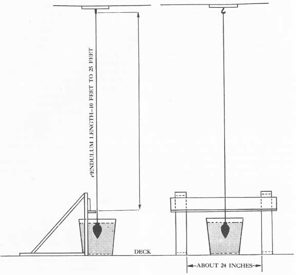
A-5. Pendulum. The pendulum used for measuring the angle of heel consists of a plumb bob suspended by a light flexible wire. Any weight heavy enough to keep the wire or string taut may be used for a plumb bob. The pendulum should not be less than 10 feet long. In the case of large ships, the pendulum should be from 20 to 25 feet long.
To obtain sufficient length, the pendulum probably will have to pass down through a scuttle or hatch. The tangent of the angle of rotation (change of list) -tangent θ-is obtained by measuring the distance the pendulum wire moves along a horizontal batten board and dividing this distance by the length of the pendulum. To dampen secondary oscillations of the pendulum the plumb bob is immersed in a bucket of heavy
335
Figure A-1. Assembly of pendulum described in Article A-5.
lubricating oil. For greater accuracy it is suggested that two or possibly three pendulums be set up at various locations in the ship. See figure A-1 for assembly of a pendulum.
A-6. Preparatory measures. Before conducting the experiment, certain measures should be taken to prepare the ship for the inclining.
Before inclining the ship should have little or no list. If the purpose of the check inclining experiment is to determine the stability characteristics of the ship for future operations, the ship and its loading should be brought as near to the prospective condition of operation as possible. This will require that tanks be filled to approximate the operating condition. If free surface is to exist in the ship's tanks during
operation, it should be present when the ship is inclined. Stores and ammunition that will be aboard during the future operation should be brought aboard and stowed in proper location. Liquids in the machinery plant should approximate operating levels.
An approximate calculation of the existing GM should be made. If negative GM is suspected, ballast should be added to correct this condition before the inclining. Remember that there is to be an inclining weight on the deck during the experiment, and that there may be considerable free surface in the ship's tanks.
There should be a minimum number of crew and officers aboard during the inclining. Only those actually needed for the experiment should remain.
336
Although all of the crew must be aboard in actual operation, the movement of the men on the ship during the inclining will produce greater errors than that introduced by their absence.
The inclining weight or weights should be brought aboard while the ship is still alongside the pier. Have the pendulum or pendulums set up beforehand, and their lengths measured.
A means of communication should be established between the location of the inclining weights, the pendulum, and the officer-in-charge of the experiment. He will locate himself on the bridge unless a clear view of all mooring lines is obtainable from the deck where the inclining weights are located. In that case the officer-in-charge should be stationed at the weights. Ship service phones, sound-powered phones or messengers will serve as means of communications.
A-7. Mooring conditions. If possible, the ship should be inclined in calm water, with little or no wind blowing. However, when such conditions do not prevail, try to locate the ship so as to take the wind bow on or dead astern. If this is not possible, then attempt to have the ship on the lee side of a pier so that it will not be driven into the pier by the wind. If on the lee side, the wind will push the ship away from the pier and there will not be danger that the ship will bump the pier during the inclining. With all conditions of wind mooring lines should be reduced to a minimum and singled up.
A-8. Shore leads. Shore power leads, steam lines, and water hose should be secured and removed from ship. If necessary, however, they may be retained, provided that there is sufficient slack in them. These lines should never be taut. The power lead may have to be retained to supply power to winches for moving weights.
A-9. Conduct of the experiment. With the ship ready for inclining, inclining weights aboard and in position, (i.e., on centerline if possible), pendulum set up, lines singled up and extra crew put ashore, the actual experiment may begin.
The gangway is removed and lines are eased until the ship is 5 to 10 feet away from the pier. Keep as many lines slack as possible; those that are unavoidably taut should be taut during all readings.
After the vessel has been moved away from the pier, read drafts forward and aft, both port and starboard. Use a whaleboat or a punt for reading drafts. Reading from the pier will give inaccurate data, especially if the ship has even a slight list. When there are two
sets of draft figures at the bow or stern, the Arabic numbers (0, 1, 2, 3, and so on) are navigational marks; the Roman numerals (X, XI, XII) are the displacement marks; the latter should be used. When there is only one set of draft marks they will be Arabic and are used as both navigational and displacement marks.
The initial position of the weights should be marked on the deck with chalk or crayon. With the inclining weights in position the location of the pendulum is marked on the batten board as zero. (There may be slight oscillations of the pendulum; the average position should be marked.) Try to locate this zero position at least twice to obtain an average position.
When the pendulum recorder signifies that he has marked his zero position, the condition of the lines should be noted and all future readings by the pendulum recorder should be made when the lines are in the same condition of tautness.
After preparations indicated above have been made, the inclining weights are moved athwartship to starboard (or port). When the weights are moved outboard as far as possible and secured from further movement, the distance moved in feet is measured, recorded, and reported to the calculator.
As the weights are being moved, the pendulum recorder will have to move the bucket of lubricating oil so that the pendulum will not touch the sides. After the weights have been secured, all personnel move back to the centerline and on word from the officer-in-charge of experiment, the pendulum recorder marks the new location of the pendulum wire on the batten board. Then after two or three minutes the pendulum is read again to check the previous marking. An appreciable difference between these two readings indicates a change in conditions, the cause of which must be ascertained and eliminated. The distance in inches between this average mark and the zero mark is measured and reported to the calculator.
The inclining weights are moved to the other side of the ship and the measurement of weight movement and pendulum deflection are recorded. All distances are measured from the initial position.
A-10. Calculations. The experiment is now concluded except for the calculations. After the drafts are read and reported, the calculator must determine the displacement of the vessel from the ship's curves of form. (Where a portion of the ship is missing, the displacement must be estimated by the best means at hand.) Then as each weight movement and pendulum
337
deflection is reported, the value of GM is calculated as follows:
GM = wd / (W tan θ)
Where: wd = moment of the inclining weight (foot tons).
tan θ = a/l
W = displacement of ship (in tons). a = distance pendulum moved along batten board (inches). l = length of the pendulum (inches).
The various values of GM thus determined should then be averaged. If the individual GM values differ materially, the weight should be moved out to either side again and another set of readings made as a check. Unless close agreement is obtained, the results cannot be considered reliable.
A-11. Evaluation and use of results. The GM thus obtained is for the ship with the inclining weights on board and with most of the crew ashore. For most ships the inclining weights will be approximately equal to the weight of personnel and located at about the same height above the keel. Therefore the GM obtained from the check inclining experiment can be used directly for future operations.
If The Inclining Experiment Booklet contains a curve of static stability for the ship at approximately the same displacement as when inclined; this curve may be corrected for the new position of G.
A-12. Summary. A chronological summary or check list of the various steps taken in preparing for and executing the experiment is as follows:
Preparatory measures:
1. Bring ship as near to prospective condition of operation as possible.
2. Before inclining ship should have little or no list.
3. Assure positive GM before inclining by approximate calculation (ballast if necessary).
4. Assign personnel for the experiment.
5. Set up pendulums and measure their length.
6. Place inclining weights on board.
7. Put ashore personnel not required for the inclining experiment.
8. Cast off steam and water hose and shore power cables.
9. Single up mooring lines.
10. Remove the gangway and ease up lines.
Execution of the experiment:
1. Read drafts.
2. Mark the location of inclining weights on the deck.
3. All personnel on board take positions on centerline of vessel.
4. Mark zero location of the pendulum.
5. Move inclining weights athwartship to starboard. Secure weights after moving.
6. Measure distance moved from the initial position. Report to the calculator.
7. Personnel return to positions on centerline of the ship.
8. Measure deflection of the pendulum. Report to the calculator.
9. Move inclining weights to the other side. Repeat as in 5, 6, 7 and 8.
10. Calculate GM, and correct new stability curve.
338
APPENDIX B
SYMBOLS
a
Any designated area in square feet.
A
Axis of cross-curves.
A.P.
After perpendicular.
B
Center of buoyancy.
b
Breadth of compartment or tank in feet.
BM
Transverse metacentric radius in feet.
BM'
Longitudinal metacentric radius in feet.
C.F.
Center of flotation.
C.G.
Center of gravity.
D
Draft in feet.
d
Distance a weight is moved off-center in feet.
F
Any force in tons.
F.P.
Forward perpendicular.
F.W.
Fresh water.
G
Ship's center of gravity.
Gv
Ship's virtual center of gravity.
g
Center of gravity of a weight, or geometric center of an area or volume.
GM
Transverse metacentric height in feet.
GM'
Longitudinal metacentric height in feet.
GZ
Righting arm in feet.
h
Height above base line of the center of gravity of a weight in feet.
I
Transverse moment of inertia of waterplane in feet4.
I'
Longitudinal moment of inertia of water-plane about transverse axis through center of flotation in feet4.
i
Transverse moment of inertia of an area about its own center in feet4.
K
Bottom of keel at midship section; i.e. base line for all vertical measurements.
KB
Vertical distance from K to center of buoyancy in feet.
KG
Vertical distance from K to ship's center of gravity in feet.
KM
Vertical distance from K to transverse meta-center in feet.
KM'
Vertical distance from K to longitudinal metacenter in feet.
L
length of ship (unless otherwise specified, it is length between perpendiculars) in feet.
l
Length of tank or compartment in feet.
M
Transverse metacenter.
M'
Longitudinal metacenter.
M.P.
Mid-perpendicular, or midship section.
MTI
Moment to change trim one inch, in foot tons.
p
Virtual center of gravity of a body of loose water.
s
Surface permeability factor.
T.P.I.
Tons per inch immersion.
t
Distance weight moved longitudinally in feet.
V
Volume of displacement in cubic feet.
v
Volume of a part of a ship in cubic feet.
W
Weight (or displacement) of a ship in tons.
w
Small weight on board ship in tons.
W.L.
Waterline.
wl
Surface of water in tank or compartment.
z
Vertical distance a weight is moved in feet.
θ(theta)
Transverse inclination of ship (angle of heel) in degrees.
339
INDEX
(Note: Items indexed by Article; e.g., 10-2 refers to Chapter X, Article 2.)
Able, 22-8.
Access openings, notes on, 30-22; via cofferdams, 34-19. Aggregate, 37-2.
Air tests, 30-8.
Alcohol, 31-4.
Algebra, 2-2.
Allowance lists, 35-1.
Alterations, and insuring watertight integrity, 30-4.
Analysis; basis for, 18-1.
Announcing system; (4MC) general (1MC), 28-6. Armor; protection, 1-5.
As-inclined condition, 9-3.
Attack; missile, 1-4; types of, 1-3; underwater explosion, 1-6.
Axis, 4-5.
Baker, 22-8.
Baskets; strainer, 35-3.
Battle; bill, 23-1; damage, 34-1; dressing stations, 23-2; engineer department stations, 39-3; engineer responsibilities, 38-2; equipment, 25-4; lockers, 25-4; telephone circuits, 28-2, 28-3,28-4.
"B" strakes, 16-6.
Beaching; possibility of, 17-11.
Beam theory, 16-2.
Bilge strakes, 16-6.
Blast suppression, 15-14.
Boat boxes and raft kits, 25-4.
Boilers, damage to in action, 39-6. Booklet of Inclining Experiment Data, 9-1, 9-6; items from, 9-7,10-7,11-1,13-9.
Box patch, 34-14.
Brazing, 34-33.
Breaking up, 1-2.
Bulkheads; holding, 15-3, 8-10; water pressure on, 36-9.
Buoyancy, 3-1; center of, 3-6; curve of, 10-6; loss of reserve, 13-4; reserve, 3-4; reserve after damage, 17-6;vertical center of, 11-7.
Cables; electric, 30-4,34-27; long, 34-31.
Calcium chloride, 37-2.
Canvas; apron, 35-3; belt, 35-3; fire retardant treated, 31-3. Capsizing, 1-8.
Carbon-dioxide systems, 32-9.
Casualties; of fire damage, 33-3; latent, 33-4; secondary, 33-5.
Calking, 34-23.
Causes of loss, 1-2.
Centerline compartment; effect of free communication on, 8-15.
Center of buoyancy, 3-6.
Center of gravity, 2-7.
Centrifugal pump, 29-4; gasoline driven, 32-11.
Chain of control, 23-4.
Check-off lists, 27-2.
Chemical warfare, 25-15.
Chest; shoring, 36-16.
Clamps; beam, 35-3.
Classification; of ships, 1-1.
Clips, 36-19.
Closure; material conditions of, 22-8,30-4.
Cofferdams, 34-18; access via, 34-19.
Collecting stations, 25-4.
Collision, 1-7; mats, 34-13.
Combustibles carried; limiting of, 31-4; storage and protection of, 31-5.
Communications, 25-5; bills, 28-10; dangers of over-centralization, 28-11; other means, 28-6; primary, 28-5; telephone, 28-2,28-3,28-4.
Compartment; check-off lists, 22-12; sub-division, 1-8. Compressed-air system, 29-23.
Computation of metacentric radius, 3-12.
Concrete; applications of materials, 37-3; materials needed, 37-2; setting time, 37-4; use of in repairing hull damage, 37-1.
Conductors, 34-27,34-29.
Contact explosions; under bottom, 15-8; side, 15-6. Corpsmen, 25-9.
Corrective measures after underwater damage, 19-7; counter-flooding, 18-7; effectiveness of, 17-4; negative GM,19-11; positive GM, 19-9; types of, 18-2.
Corrosion, 30-3.
Cosine, 2-3.
Counterflooding, 18-7.
Couple, 2-6,3-7.
Couplings, 34-24; and special clamping devices, 34-25. Cross-curves of stability, 4-5; corrections, 6-4; uses of, 4-6. Cruising radius reduction, 21-4.
Curves, cross-curves of stability, 4-5, 6-4; displacement, 3-3, 3-6, 11-1, 11-4; form, 11-1, 11-14; others, 11-13; righting moment, 4-7; static stability, 4-3; tons per inch immersion, 11-5; transverse metacentric height, 3-13.
Damage; advancing flooding boundaries, 34-4; battle, 34-1; boilers in action, 39-6; casualties, 33-3; control book, 21-3; control stations, officer-in-charge of, 21-11; extent, determination of, 19-2; holes in hull, 34-5; investigation of, 33-1, 33-4, 33-6, 34-3; limitation of, 38-5;
340
machinery and piping, 37-7; reports on, 39-2; resistance to, 1-1; structural, 33-6; survey of, 33-2.
Damage control; bills, 22-11, 23-5, 28-10; conditions of readiness for action and, 22-7; drills, 26-17; education for, 22-4; fundamental elements of, 22-2; information sources on, 22-6; library, 22-14; literature, 26-9; lumber, 31-2; maintenance program, 23-12; material and equipment, 22-14; organization, necessity for, 22-3, 23-1; purposes of, 22-1; pumping, 29-18; ships, large, 23-2; ships, small, 23-3; ship design and, 38-5; training, 22-5,23-11,34-32.
Deck; covering, 31-2, 31-3; drains, 29-7; stringers, 16-6. Density, 2-4.
Diagonal, 3-6; for KB and KM curves, 11-6; weight shift, 6-6.
Diesel-driven fire pumps, 29-4.
Displacement, 3-3,4-4,7-2; change for trim by stern, 10-4, 11-2; curves, 3-3, 3-6, 11-1, 11-4; limiting of, 21-4; minimum, 21-4.
Docking plan, 11-3.
Draft, change of on flooding effect diagram, 10-14; diagram, 11-3, 11-15, 11-16, 11-17; displacement, 7-2; marks, 11-2; reading, 11-3; weight movement, effects on, 10-10.
Drag, 10-15.
Drainage systems; gravity, 29-7; main, 29-10; mechanical, 29-8; secondary, 29-11; separate, 29-12.
Drains, deck, 29-7; open funnel, isolation of, 38-11. Drills, 26-17; repair party, 27-3.
Dynamic stability, 4-9.
Education; activities, examples of, 26-13; presentation, methods of, 26-8; subjects, general, 26-6; starting program, 26-12; topics suggested, 26-7; visual aids, use of, 26-10.
Eductors, portable, 29-15.
Emergency sound-powered telephones, 28-4.
Engineer department; damage control and, 38-1; dispersal of personnel, 38-14; personnel and organization, 38-6; publications for study, 38-3; split-plant operation, 38-7; in port, 38-13; training, 38-15.
Engineering; bills, 23-5, book, 29-5, 38-8, 38-9; department, battle stations for, 39-3; damage, 39-1; force and repair parties, 24-4, 39-4; plates and diagrams, 38-8.
Equipment; adequate, 21-9; fire-fighting, 32-4; operation of, 30-21; protective, 32-13.
Exponents, 2-2.
Files and records, 31-4.
Fire, 39-14: bills, 32-18; control, 23-1; hazards, 31-1,31-2; hose and nozzle, 32-7; marshal, 31-6; retardant material, 31-7,32-16; severe, 1-2; spreading of, 33-7.
Fire-protection officer, 31-6.
Fire fighting, 19-4; difficulties of, 32-19; group action in, 32-17; organization for, 32-14, 32-15; parties, 24-4, 32-15.
Fire main; elements of, 29-4; fouling of, 32-4; weekly inspection of, 32-5.
First-aid posts, 23-2; equipment for, 25-4.
Fittings; classification of, 22-9; examples of, 22-10; with watertight integrity, 30-4.
Flanges; blank, 34-26.
Flexibility; of hull piping systems, 29-2.
Flooding, 1-2; additional factors in, 13-9; boundaries, determination and establishment of, 18-3; control of, 29-16; draft, changes of, 10-14; effect diagram, 9-8; how it takes place, 13-5; loss by, 1-8; partial, 13-7; ship girder and, 16-22; solid, 13-6.
Flotation; center of, 10-3; adding weight at, 10-11, 11-11.
Fog and sprinkler heads, 32-5.
Force, 2-5; at rest, 3-5; outboard, 3-7.
Fragment and flash suppression, 15-14,15-25.
Framing; bottom, 16-16; transverse, 16-7.
Freeboard, 3-4, 4-4; reduction of, 21-4.
Free communication; constriction of, 13-9; effect of, 8-12; evaluation of, 8-14; visualization of, 8-13.
Free surface; breadth of, 8-8; bulkheads and, 8-9; effect on stability, 8-2; evaluation of effect, 8-4; location of, 8-7; pocketing and, 8-10; ship's tanks and, 13-9; suppression of, 18-4; variables of, 8-10; visualization of, 8-3.
Fresh water; for concrete, 39-2; system, 29-20.
Fuel oil; hull piping system, 29-1; sequence table, 9-8; transfer, 29-19.
Furniture, upholstered, 31-2.
Garboard strakes, 16-6.
Gas; incandescent, 15-4.
Gas masks, 32-13.
Gasketed covers, 30-4.
Gasoline, 31-4.
Gear; for hull piping systems, 29-2; miscellaneous, 36-8; rigging, 36-7; topside, 31-4.
Generators; foam, 32-8.
General quarters, 22-7; medical department stations, 25-3. General Information Book, 29-3.
General stability diagram; data needed for, 12-4; description of, 12-2; purpose of, 12-1; results, dependability of, 12-5; uses of, 12-3.
Girder, 16-6.
Glass; cloth of, 31-3; fiber and block insulating material, 31-3.
GM; calculation of, 17-5; impaired and unimpaired, 14-4; on stability curve, 4-10,7-3.
Gravity; center of, 2-4, 2-7; finding of in ships in design stage, 5-2.
Handy billy pump, 29-15,32-10.
Heel; angle of, 4-2,7-4.
High-explosive magazines; protection of, 15-25.
Hogging stresses, 16-5.
Holding bulkhead, 15-13.
Holes in hull; above waterline, 34-6; flooding effect of, 34-7; temporary repairs, 34-9; types, 34-8; under waterline, 34-5; wooden plugs and, 34-10.
Hookbolts, 34-14.
Hull; allowance list, 22-14, 30-20; board, 30-11; flooding effects of holes in, 34-7; holes in under waterline, 34-5; holes in above waterline, 34-6; piping systems, 29-1; repair book, 29-3.
Hull piping systems; compressed air, 29-33; construction of, 29-2; condenser-circulating, 29-8; damage-control, features of, 29-2; drainage, 29-7, 29-8, 29-10; fire main, 29-3; fresh water, 29-20; fuel-oil transfer, 29-1; gasoline, 29-21; importance of, 30-12; salt water, 29-1; sea-flooding, 29-17; secondary drainage, 29-11;
341
sprinkling and flushing, 29-6; ventilation, 29-22.
Hydrostatic pressures, 16-13.
Keel; flat, 16-6.
Kerosene, 31-4.
KG; alternative formula for, 7-7.
Knife edges and bearing surfaces, 30-4.
Ladder; portable, 35-3.
Leaks; armored hatches, 34-17; cracks, 34-16; rivets and, 34-17; torn seams and, 34-17; vacuum, 34-27.
Lever arm, 3-7.
Liquid; density of in relation to free surfaces, 8-5; level in wing tanks, 15-25; loading procedure, 21-3; optimum distribution of, 15-15.
Lighting detail, 24-4.
List; causes and effects of, 14-6; correcting of, 14-8, 17-10; danger of operating machinery with, 39-5; feel of, 14-4, 14-5; minimum, 21-7; minimizing of, 15-25; nature of, 14-2; suppression of, 15-14; variations in angle of, 14-3.
Literature, 26-9.
Local strength, 16-12.
Loading; conditions of, 9-2, 9-6; dynamic, 16-17; light
condition, 9-5; standard condition, 9-4.
Longitudinal; inclinations, 10-1; stability, 1-8,10-6. Loose water, 8-1, 18-5.
Loss, by fire, 1-10; by flooding, 1-8; by immobilization, 1-11; by magazine explosion, 1-12; by structural failure, 1-9.
Lubricating oils and greases, 31-4.
Luggage; combustible, 31-2.
Machinery and piping, damage to, 39-7; readiness of auxiliary, 38-10; securing of unnecessary, 38-12.
Magazine; explosions, 1-2; sprinkling system, 29-17. Maintenance; of fire-resistant condition, 31-6; importance of, 15-18; of medical department equipment and supplies, 25-11; planned program of, 30-13; program for repair equipment, 30-20.
Mathematics, basic principles of, 2-1.
Medical department; corpsmen, 25-9; chemical warfare and, 25-15; decentralization of, 25-2; disposition of dead and wounded, 25-14,25-13;
emergencies other than action, 25-6; equipment and material, 25-4; first aid, 25-12; general quarters stations, 25-3; maintenance of equipment, 25-11; stretcher bearers, 25-8; training methods, 25-10.
Metacenter, 3-8; transverse, 11-8.
Metacentric height, 3-9; computation of radius, 3-12; curve of transverse height above keel, 3-13; influence of, 3-10; negative, 14-15; radius, 3-8, 11-9; relationships of, 3-11.
Metal shapes, 36-19.
Minimum liquids, 21-3.
Missile attack, 1-4.
Mobility and maneuverability, 17-10.
Mockups, use in training, 34-33.
Moments, 2-6; of inertia, 2-9, 4-4; trimming, 10-8; to change trim, 10-7,11-10.
Movement; general effect of weight, 6-2.
Negative metacentric height, 14-5.
Non-contact explosions; at the side, 15-7; under the bottom, 15-9.
Non-essential combustibles; elimination of, 31-2.
Non-inflammable items; replacement with, 31-3.
Off-center weight, 14-2.
Officer-in-charge, damage-control station, 21-11.
Oil and water leaks; detection of, 30-6. Operation, test, and inspection, 30-15.
Organization and training, 21-10.
Over-centralization; dangers of, 28-11.
Paint; fire retardant, 31-3,31-4.
Painting, 16-18.
Paper and office supplies, 31-4.
Partial flooding, 13-7; in free communication with the sea, 13-8.
Parties; fire, 24-4, 32-15; repair, 23-2, 39-4; securing and salvage, 39-15.
Patches; improvised, 34-13; Jubilee pipe, 34-23; other types, 34-23; prefabricated plate, 34-12; soft, 34-22; special, 34-14; welded, 34-15.
Patrol, 24-4.
Pendulum, A-5.
Permeability; beneficial effects of, 8-10; surface, 13-9; volume, 13-9.
Personnel; damage-control station, 23-7; engineering department, 38-11; repair party, 24-3; to be trained, 26-5. Pipe; lines, blanking, 34-26; sections, renewing of, 34-24; shores and, 36-19; unions 34-24.
Piping; fire main system, 29-4.
Plating; in compression, 16-8.
Plugs; pillows, mattresses, etc., as such, 34-11, 34-13; wooden, use of, 34-10, 34-23.
Plunging, 1-8.
Pocketing, 8-10,13-9.
Portable submersible pumps; characteristics of, 29-13; operation and maintenance of, 29-14.
Portland cement, 37-2.
Pouches; hospital corps, 25-4.
Power; sources of in DD's, 38-7.
Preparatory measures; importance of, 21-1.
Pressure; hydrostatic, 16-13; due to flooding, 16-14; pulse, 15-4.
Tactical situation, 17-10.
Tangent, 2-3.
Telephone talkers; battle circuits, 28-2; message form and procedure, 28-9; rules for, 28-8.
Telescopic shore, 36-5.
Tests and inspections, 30-5; check tests, 30-19.
Tons per inch immersion curve, 11-5.
Tools, improvised, 35-3; markings, 35-2; storage for small 35-4; storage for large, 35-5.
Topside weight; addition of, 13-2.
Torpedo; depth, 15-17; at mid-depth, effect of, 15-22; shallow and deep, effect of, 15-23.
Torpedo-protection systems; classes of ships designed with, 15-11; design features of, 15-13; functions of, 15-14; purpose of, 15-12; situation after damage, 19-6.
343
Towing vessel, 17-11.
Training and education; damage repairs, 34-32; engineering personnel, 38-14; organizing for, 23-11.
Training activities, 26-1; methods, 26-16; objectives, 26-15; personnel to be trained, 26-5; realism, methods of introducing, 26-14; the repair party, 27-1; training of instructors, 26-4.
Transverse metacenter, 11-8.
Transverse stability, 1-8; effect of trim, 10-17; free communication effect on, 8-12.
Trigonometry, 2-3.
Trim, 10-2; calculations of change of, 10-9; change of, 10-5; effect on transverse stability, 10-17; excessive, 10-16, 13-9; operation, 10-15; optimum, 12-6; suppression of, 15-14, 17-10.
Tours and demonstrations, 26-11.
Trimming moment, 10-8.
Underwater explosions; types of, 15-2; at bow and stern of small ships, 16-21; contact at side, 15-6; contact under the bottom, 15-8; damage to large ships, 16-19; effects of, 15-5; nature of, 15-4; non-contact at side, 15-7; progress in research on, 15-3; small ships and, 16-20. Underwater hit near ends; effects of, 15-24.
Underwater protection, 1-6.
Universal wrench, 35-3.
Upper decks and superstructure, 16-11.