29-1. Foreword. In addition to the engineering plant, certain piping systems are installed to provide services that are essential both when cruising and in battle. The operation and maintenance of these hull piping systems are under cognizance of the damage control officer and first lieutenant, with the exceptions noted in footnotes 1 and 2 below. The systems are as follows:
1. Salt-water.
Pumping.
a. Fire main.
b. Sprinkling.
c. Flushing.
Drainage.
a. Main drainage.
b. Secondary drainage.
c. Sanitary drainage.
d. Gravity drainage.
Flooding and ballasting.
a. Sea flooding.
b. Damage-control ballasting.
c. 1Fuel-oil ballasting.
2. 1Fuel-oil.
a. Filling.
b. Stripping.
c. Transfer.
3. Miscellaneous.
a. 2Gasoline.
b. Fresh water.
c. Ventilation and mechanical cooling.
d. 1Compressed air.
e. Portable pumps.
29-2. Damage-control features of hull piping systems. Because the services of these systems are essential, they have been constructed and installed to:
Withstand damage to the highest practicable degree by virtue of construction and the location and arrangement of important features. This involves protection by armor and other structure, and adequate dispersion.
2. Minimize loss of services after damage has been sustained because of carefully marked out design, including valving.
3. Permit prompt re-establishment of the maximum possible service, after damage, because damaged and inoperative portions may be isolated or cut out of the system, thus restoring the functions of the undamaged portions.
4. Provide means for operating important valves, pumps and other structures both locally, and remotely from areas which are less susceptible to damage or are likely to be most accessible after damage.
It is necessary that damage-control personnel be well acquainted with all features which have been incorporated for the above purposes if they are to utilize them to advantage in emergencies.
The designed and installed features which offer resistance to, and control of damage may be classified as follows:
Protection. Systems are installed to provide certain inherent resistance to damage. In all ships the run of main piping is located so that shell, bomb, or torpedo damage will produce the minimum effect. In armored ships these runs usually are inboard of vertical armor and below horizontal armor, taking full advantage of protection thus afforded.
In addition to location, construction details of the systems are carefully studied. Recognizing the widespread and devastating effect of blast accompanying the explosion of bombs, torpedoes and projectiles, and the concomitant waves of destructive vibration, all piping, fittings, controls, pumps, etc., are constructed and installed to resist shock. Brittle materials, such as cast iron are not used, and such modern innovations as welded piping and silver-soldered joints are employed to increase damage resistance. Unfortunately,
1 The engineer officer has cognizance over portions of these systems. 2 The air officer also has cognizance over operation of the gasoline system.
208
some of these new features enhance repair difficulties; a fact which must be anticipated by damage-control personnel.
Since all piping systems provide possible avenues for progressive flooding after damage, piping systems are arranged to minimize this hazard. Every effort is made to restrict the piping penetrations of main subdivision bulkheads below the tightness level. Generally, mains of systems such as ventilation, fresh water, flooding, etc., which are not essential because their destruction would not directly cause loss of the ship, are run fore-and-aft just below the lowest weather deck. In all cases, vertical runs of risers for these systems do not pierce the main subdivision bulkheads below this tightness level.
Sectionalization. Vital hull systems are arranged so that they can be segregated into smaller operating units by means of valves. Thus, in the event of damage, the surviving units can provide continuous service to unaffected portions of the ship. A sectionalized system requires more than one prime source of service (pumps, pressure tanks, blowers, etc.), so that service is available to each portion thereof. The prime sources are distributed throughout the ship so that no single damage is likely to render more than one of them inoperative.
Flexibility. A system is flexible if its component parts may be operated in several different combinations. Such flexibility facilitates resumption of service after damage. Some of the features involved are as follows: First, parallel runs of main piping are provided on opposite sides of the ship or at different levels where this is possible, with pumps or prime sources of service centrally located and serving both mains through valved cross-connections. This arrangement provides means for continued service through a main when the side opposite is damaged. Sufficient cross-connections are installed to permit sectionalized operation in loops. Second, the pumps, or sources of service, are powered by different prime movers where possible; e.g., steam, electric, or Diesel drive. This provision tends to guarantee continued service if one source of power fails. Third, provision of additional valves strategically located in each section permits close isolation of damage so that the intact portion of the section may still be used to serve the area affected, and repairs are correspondingly facilitated.
Control. Since vital piping mains are run below the armor deck or below other structure for protection, key valves frequently are in locations difficult to reach. Local operation of such valves from compartments not
manned at general quarters would require opening of watertight doors and hatches, thus violating watertight integrity under battle conditions. Furthermore, the amount of time needed to reach a valve is likely to be of critical importance. Therefore, remote-operating gear is provided in many cases to permit operation of key valves in unmanned compartments by personnel in stations normally manned or readily accessible. The four types of remote-operating gear include: (1) mechanical (manual), (2) hydraulic, (3) electrical, and (4) pneumatic. Regardless of type, however, such gear must be shock-resistant, rugged, and generally dependable, especially after damage.
Mechanical remote-operating gear originally was represented by arrangements of reach-rods connected by universal joints and bevel gears, and made watertight at deck and bulkhead penetrations by means of stuffing boxes. This type of gear (especially when the linkage is long) has sometimes proven unreliable, particularly after damage. Relatively small distortion of components or faulty maintenance results in "frozen gear," which fails to function when urgently needed. Thus, where practicable, new ships are fitted with flexible cable type mechanical remote-operating gear which has been very reliable and satisfactory in service. The torque which such a device can transmit is limited, however, and its remote operation may be comparatively slow. In addition to manual operation, some valves are equipped with hydraulic remote-operating arrangements, powered by hand gear pumps or lever operated oil pumps at control stations. Each pump usually serves several valves in a designated area via a selective hydraulic valve arrangement at the operating station. Experience to date indicates that such installations are rugged and dependable in action, although the oil piping involved is susceptible to damage.
Magazine sprinkling system valves of large ships are operated by electric, hydraulic or pneumatic remote control, in addition to local manual arrangements. The electric system is of the push-button type, controlling small motors or solenoids at the valves. The pneumatic system consists of a small hand air pump delivering air pressure to open a small pilot valve, which in turn allows fire-main pressure to operate the sprinkler valve. Pneumatic-control systems also have been installed on drainage and fire-main valves of some ships, but such a system operates in one direction only (i.e., to open or to dose); the opposite operation must he manual.
All remote-operating gear must be tested regularly and frequently to assure readiness when it is needed
209
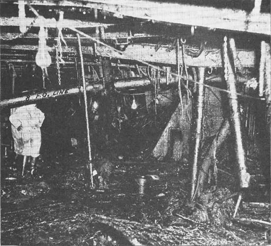
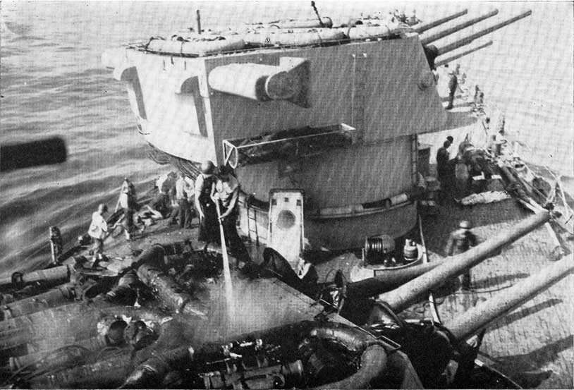
Figure 29-A. A photograph of actual damage involving ruptured piping.
critically. Defects disclosed by tests must be eliminated without delay.
FIRE-MAIN SYSTEM
29-3. Know the fire-main system. A complete knowledge of the fire-main system is requisite to readiness for damage control. This is equally true in the case of damage-control personnel, engineering personnel and members of the gunnery department directly concerned with magazines and handling rooms which are sprinkled from the fire main.
It is necessary, therefore, that all information and data concerning the fire main, in the form of blueprints, diagrams, damage-control plates, descriptions, and records of repairs and alterations be readily available to the damage control officer and all other personnel
concerned. Most of the information in question will be found in the following sources:
1. General Information Book.
2. Damage Control Book.
3. Hull Repair Book (or similar repair or test record).
There can be no substitute, however, for the knowledge gained by actual study of the fire-main system on board ship. Following the piping from one end of the ship to the other, deck by deck and compartment by compartment, is the most practical method of studying this system. Supplemented by a conscientious study of the prints, diagrams, and similar related data, this experience will give any officer or enlisted man a good knowledge of the fire main. Any discrepancies between the actual system and the written descriptions
210
will be discovered at once and corrected. The penalty for an incomplete knowledge of the fire main and its operation may be the loss of a ship and many lives in battle.
Ordinarily, the fire main supplies water pressure for several other cruising and battle systems. Among them are the flushing system, magazine sprinkling system, fuel-oil tank ballast system, eductors, gasoline drainage system, salt water displacement systems, and cooling systems for various machinery units such as oil coolers. The capacity of a fire-fighting system is designed to simultaneously fight a number of fires, yet reserve sufficient water to sprinkle spaces containing hazardous material and to supply certain vital services. Careful consideration of valve settings is essential in order not to "starve risers" supplying fire hoses when emergencies require diversion of some of the system's capacity for sprinkling magazines or pumping flooded spaces. The possibility of such simultaneous demands must be foreseen, and preparations made to meet the situation.
29-4. Elements of a fire-main system. The elements of a fire-main system include pumps, piping, valves, and other controls. Fire pumps aboard ship are classified according to use as (1) fire pumps, (2) fire and bilge (drainage) pumps, (3) fire and flushing pumps, and (4) fire, flushing and drainage pumps.
Any pump installed for use as a fire pump must be designed to deliver an adequate volume of water at a pressure sufficient to operate fog nozzles efficiently at the upper deck levels. On the largest ships fire pumps are designed to operate at 150 pounds per square inch pressure; on destroyers the corresponding figure is 100 pounds per square inch pressure.
Different types of pumps are installed in fire mains. They may be classified as follows:
1. Steam driven reciprocating fire and bilge pumps.
2. Centrifugal pumps, driven by:
a. Steam turbines.
b. Electric motors.
c. A combination of turbines and electric motors.
d. Diesel engines.
The steam-driven reciprocating pump is very reliable, and usually is located in a boiler room or machinery space in close proximity to a source of steam. Its capacity is relatively small, however, running from 100 to 400 gallons per minute. This is a standard fire pump for small ships up to the size of the later destroyers. As the size of the ship increases this type of pump is supplemented, and, in the latest large ships its customary fire-main services are entirely provided
for by centrifugal pumps. Centrifugal pumps may be driven by either steam turbines or electric motors. On the later battleships some of the fire pumps have an electric motor directly connected to one end and a steam turbine directly connected to the other. Hence the pump can be driven either electrically or by steam.
On later large ships certain electric motor driven pumps are located close to or in the same spaces as emergency Diesel generators. This gives the pump an alternate source of power close at hand. Thus increasing its reliability.
Since the outbreak of the war, Diesel-driven fire pumps have been installed on many ships. They are reliable and dependable fire pumps that prove particularly useful when the main sources of power are unavailable. One very good design has a motor whaleboat type Diesel engine directly connected to a centrifugal pump, and can deliver approximately 1,000 gallons per minute at a pressure of 125 pounds per square inch.
Fire-main piping in general use today is made of copper nickel alloy. Some ships have wrought-iron or galvanized steel piping. Galvanized pipe must be watched carefully for corrosion. Coating its interior surface with a plastic compound similar to the antifouling paint used on the ship's bottom, has been effected at certain of the Navy yards.
Fire-main piping may be installed as either a single-line system or a loop system. The single-line system consists of one line of piping running fore-and-aft through the machinery spaces, generally extending for some distance forward-and-aft of these spaces. Water is pumped into this main from pumps that usually are located in the machinery spaces. Pipes (risers) extend from the main to the upper levels. From these risers, pipes lead to the fire plugs. Connections to flushing and sprinkling systems and to various cooling systems (mostly in the machinery spaces) also come off these risers. Single-line fire-main systems are found on smaller ships including some of the older light cruisers. The inside diameter of the fire main on destroyers is approximately four inches, and on light cruisers five inches.
On larger and more modern ships, particularly cruisers, carriers and battleships, the fire main forms a loop. This system consists of two fore-and-aft runs of pipe separated by the width of the ship throughout their length, and joined together at their ends to form a loop. These fore-and-aft runs are also connected at intervals (usually once in each main transverse subdivision of the ship) by piping generally designated
211
as cross-connections. The plane of the loop may be either horizontal, vertical, or in some cases at an angle. When the plane is horizontal, it is usually below armored protection. When the plane is vertical or at an angle, the lower horizontal lead is located so as to be somewhat protected from projectile, bomb or splinter effects, while the upper lead is run so as to be fairly safe from underwater damage. Combinations of loops have been employed to advantage; for example, a small carrier had a horizontal loop below the hangar deck which served risers to the hangar sprinkling, and a single main fore-and-aft below the third deck, connected by vertical risers into the horizontal cross-connections of the upper loop. This arrangement resembled an inverted basket in form. Generally speaking, many combinations are possible, the "best" necessarily being in terms of the specific ship.
The fore-and-aft extent of a loop is usually governed by the extent of armor protection. Beyond this protection single-line extensions run to the ends of the ship. On larger ships pipe forming the loop may be as large as nine inches in diameter, with cross-connections and end extensions somewhat smaller.
Practically all fixed fire pumps are located in compartments below the waterline, and take suction from the sea through a sea chest (with a strainer), a stop valve, and suitable suction piping. This suction piping may come to the pump directly, or lead into a manifold from which the fire pump takes its suction. Other suction piping to the manifold may lead from the drainage main, bilge wells, etc. Some fire pumps also may be used as drainage pumps.
Fire-main systems are designed so that damage to one section need not necessarily rob the entire system of water pressure. To accomplish this, cut-out valves are located at principal watertight bulkheads, and in other strategic places. Cut-out valves located in the fire main proper, and its cross-connections, are known as main cut-out valves. Some are capable of remote operation. Riser cut-out valves are located in the individual risers. Individual cut-out valves also are installed at take-offs to the flushing, sprinkling, and other systems.
Cut-out valves usually are gate valves, but may be the free-flow type of plug valve. Other valve designs occasionally are encountered, particularly in association with magazine sprinkling systems. As noted elsewhere, valves may be operated from distant locations through remote-control operating gear. Such arrangements are provided for the most important inaccessible cut-out valves. Installations have even been made on
certain carriers whereby the opening of an important valve in the fire-main system will automatically start an additional fire pump on that section of the main.
Gauges in strategic locations permit prompt recognition of fire-main damage which results in ruptures and leaks of large magnitude and consequent drop in pressure. Pump tenders must be trained to watch for such indications of damage.
In practically all ships, the fire-main piping is so arranged in compartments that sections of piping and valves may be dismantled by the ship's force for repairs, using regular shipboard tools. If a section of piping is ruptured, cut-out valves on either side of the break may be closed and the ruptured section removed by unbolting the appropriate flanges. Temporary service may be restored by connecting a length of fire hose between the open flanges. Damage control hose-flange adapters are provided in repair stations so that such temporary connections or, jumpers may be rigged. These hose-flange adapters can be bolted (or clamped with C-clamps) into place easily and quickly. The damaged section of piping should, of course, be repaired and put back into place as soon as possible. This subject is treated more extensively in Chapter XXXIV.
29-5. Fire-main sectionalization. During battle the fire main must be segregated into a number of separate and independent fire-main systems. Each of these sections must have its own source of water and be capable of being operated as an individual system without detriment to the ship's battle efficiency. Then if damage destroys one or more sections of the fire-main system, other sections will still be able to furnish fire-main pressure in areas adjacent to the damage.
Most ship's fire-main systems are so designed that sectionalization may be accomplished by the proper classification of the main and cross-connection cut-out valves, and by the use of appropriate pumps when sectionalization is put into effect. The operating procedures for accomplishing this result should be incorporated in the damage-control fire-main operating bill (fire main, sprinkling and flushing systems bill) and in the Engineering Casualty Control Book.
General instructions concerning the preparation of fire main, sprinkling, and flushing systems bills are given in FTP-170B. These instructions should be studied carefully. Remember particularly that cut-out valves in risers supplying fire plugs, fire-fighting equipment, water curtains and hangar sprinklers, and magazine sprinkling systems should be classified W. Also note that fire-main cut-out valves within segregated
212
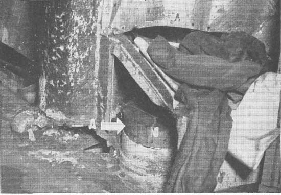
Figure 29-B. Ventilation systems are a potential avenue for progressive flooding. Observe the plug driven in this vent duct (A).
sections must be classified W. This is necessary in order to permit the formation of multiple independent systems.
Every effort must be made by the damage control officer, in collaboration with the engineer officer, to obtain that sectionalization of his ship's system which will result in the minimum loss of available fire-fighting water when damage occurs. Proper classification of fire-main cut-out valves plays an important part in establishing this condition.
Material condition x-ray:
When at anchor in a protected harbor sufficiently distant from combat areas and where surprise attacks may be considered improbable, the fire main normally is operated as a single system. In this situation, material condition x-ray usually is set and all valves classified Y, Z and W may be left open. Pressure is maintained on the fire main by the minimum number of most conveniently located pumps. All valves classified X, however, should remain closed. While material condition x-ray applies only to three-condition ships, the X classification is necessary for some valves of the fire-main system on two-condition ships.
Material condition yoke:
Certain ships realize their maximum fire-main sectionalization in material condition yoke or baker. In this case material conditions zebra or able may be set more quickly insofar as the fire main is concerned, since only a limited number of cut-out valves need be closed to attain battle condition. Other ships, however, achieve only a partial sectionalization of their fire-main system in material condition yoke or baker because of (1) pump locations, (2) available electric power, (3) a desire to have standby pumps available for emergencies, and (4) other reasons peculiar to the ship's fire-main characteristics. In sectionalization for war cruising on both two- and three-condition ships, from two to four separately operating fire-main segregations usually may be attained. Smaller ships and certain of the larger non-combatant ships operate on the two-division basis (either forward and after segregation, or port and starboard segregation). Other ships are known to operate their fire mains in war cruising condition with three or four separate and independent units. War cruising fire-main sectionalization is attained by proper classification of fire-main and cross-connection cut-out valves.
213
Material condition zebra:
As previously stated, many ships have their fire-main system segregated into its maximum number of sections during material conditions yoke or baker, and merely continue these segregations when setting conditions able or zebra. This is particularly true in the case of smaller ships, and certain of the larger non-combatant ships.
There are, however, other larger ships which go from a two- or a three-section war cruising fire-main segregation into as many as eight separate and independent fire-main units. Within reasonable limits, the more complete the sectionalization of any fire-main system, the greater will be its reliability and effectiveness after damage occurs. It is recommended, therefore, that careful study be made of the fire-main system on each ship to determine the maximum number of separate and independent systems which will be practicable during battle. Greater degrees of segregation for material conditions zebra or able than exists in material conditions yoke or baker may sometimes be attained by classifying as Z certain additional fire-main and cross-connection cut-out valves.
A further point concerning segregation of the fire-main system should be made. Damage to one independent fire-main section may be isolated so that fire-main pressure can be restored to the undamaged parts of that section. This may be done by valve operation, or in some cases by rigging jumpers. Drills requiring varied manipulation of a well segregated fire-main system in response to simulated casualties are of great value in training personnel for damage control, and also are useful for checking the effectiveness of the maintenance program.
War experience has demonstrated that a ship can be lost because of fire, through failure to realize the advantages of a sectionalized fire-main system, and due to lack of proper training for operation under damaged conditions. The fire main, flushing and sprinkling bill (one of the damage-control operating bills) must provide for the most effective practicable segregation, both in the war cruising and in the battle condition.
29-6. Sprinkling systems. Magazines, handling rooms, and ready service ammunition spaces are fitted with perforated sprinkling piping arranged to drench the bulkheads and overheads, thus reducing high temperatures due to nearby fires. This sprinkling action will also prevent the outbreak of fires in magazines when adjoining spaces are burning.
Each isolated magazine, or group of magazines in
close proximity, is supplied from the fire main through a sprinkler main with a control valve. The operation of the sprinkling control valves is exercised locally at the valves, and in many cases, remotely from conveniently located control stations.
Some spaces in which inflammables are stowed, such as aircraft wing stowages in aircraft carriers, are fitted with fixed-fog nozzle systems. Some of these systems are controlled by automatic rate of rise sprinkling devices and others by remote electrical controls. Still others are fitted with connections outside of the compartment which must be effected by running hose to nearby fire plugs.
Hangar spaces on aircraft carriers are fitted for sprinkling, and are subdivided into bays by water curtains. These sprinkling groups are controlled by electrically operated valves. Modified arrangements of these systems are fitted in hangars on cruisers.
29-7. Flushing systems. Flushing water to heads. sick bays, and similar spaces is supplied at a pressure of about 30 to 40 pounds per square inch from the fire main via branches with reducing valves, or orifices with relief valves. This arrangement replaces the complete flushing loop found on older ships.
DRAINAGE SYSTEM
29-8. Drainage for damage control. Various means are provided for removing unnecessary water from within a ship's hull. Systems of piping and pumping facilities are installed for this purpose and referred to as drainage systems.
Needless to say, these features are most important for the control of damage. However, the drainage capacities which have been provided are by no means adequate for removing water under all conditions of damage that may occur. For example, a round hole about one inch in diameter open to the sea at a depth below the waterline of 10 feet, will admit approximately 38 gallons of water per minute. If this hole happens to be two inches in diameter, about 152 gallons per minute will be admitted, and if the hole is 14 inches in diameter about 7,430 gallons per minute will flow in.
On the other hand, efficient operation of the drainage system, together with the employment of various devices by shrewd damage-control personnel to restrict flooding openings, can keep spaces operating which would otherwise have to be abandoned because of progressive flooding through small leaks such as cracks in bulkheads.
Drainage arrangements vary greatly from ship to
214
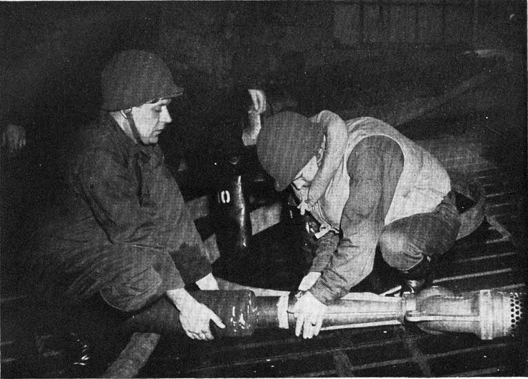
Figure 29-C. Rigging a portable eductor.
215
ship and it is not practicable to discuss all types here. General features common to most ships will be touched upon, and special features found in some ships will be noted. If damage-control and engineering personnel become thoroughly acquainted with the regular methods of drainage, improvising in emergencies will be less difficult.
Fundamentally, a drainage system consists of the following items:
1. Suction piping (drainage main).
2. Branches from the main leading into spaces to be drained, normally near the lowest point in each space.
3. Pumps (or eductors, or both) to take suction from the drainage main.
4. Discharge piping from the pumps (or eductors, or both), leading overboard.
5. Necessary valves, manifolds and strainers.
The great majority of damage incidents involve flooding. Control of this flooding is paramount. The inflow of water must be restricted or stopped entirely.
No matter how small a leak may be, the water it allows to enter must be removed or it may eventually flood not only one, but many compartments. It is noteworthy that an efficiently organized and operated bucket brigade should be able to control a leak well above 15 gallons per minute. This possibility should be kept in mind, and adequate provision made for handling flooding in this way. All ship's personnel should be made to understand, in advance, just what may be expected of them when bucket brigades are called into action. Drills may be held, in expelling water by this method, when circumstances permit.
The foregoing statements indicate the basic importance of the drainage systems. Obviously, they must receive careful attention and care. A group of alert men well informed concerning the drainage facilities of a ship and able to use them efficiently can keep the ship afloat and fighting even when severe damage is incurred.
29-9. Main drainage. The most important drainage system on a ship is the main drainage. This system is justly more important because of the quantity of water handled and the type of spaces drained. On most ships, this system runs through the main engineering spaces and, on armored ships particularly, extends generally throughout the protected portions, forward-and-aft of the machinery spaces.
Main-drain piping usually is about 6-inch galvanized steel pipe. The branches, or suction take-offs to the various bilge wells, tanks or other compartments
are of smaller sizes down to and including 2 1/2-inch pipe. Hose valves also are installed in the main, so that standard suction hose can be connected to them.
Types of valves represented in the main-drainage system include the following:
1. Stop or cut-out valves (usually for segregation or isolation of the mains).
2. Stop-check and stop-lift check valves (for more important suction branches).
3. Check valves (miscellaneous suctions).
On smaller ships the main cut-out valves can be remotely operated, usually by reach-rods. On larger ships the main cut-out valves, together with many of the important stock-check valves and stop-lift check valves may be operated from distant control stations. A careful study should be made of valve operation in the drainage systems. All damage-control personnel should know all there is to know about these valves, how they may be operated, and how they may be kept in good operating condition.
The valves in drainage piping are classified in accordance with the instructions contained in FTP-170B. In general, bulkhead stop cut-out valves at transverse watertight bulkheads should be classified X, and all other valves in the system should have the same classification unless special operations make other classifications necessary. To preserve maximum watertight integrity, valves in drainage piping should be open only when essential for a specific operation.
Types of pumps installed to take suction from the main-drainage systems are as follows:
1. Steam-driven reciprocating (usually fire and bilge) pumps.
2. Turbine or motor-driven centrifugal pumps.
3. Jet pumps (eductors).
The main drain on a small ship may have only one small-capacity fire and bilge pump installed. A new destroyer has four 200 gallon per minute fire and bilge pumps, one in each boiler room and each engine room. The newest large ships have all three types of pumps installed. The latest battleships have nine centrifugal pumps operating through eductors at 1,200 gallons per minute each, and five steam-driven reciprocating bilge pumps at 225 gallons per minute each, all installed to take suction from the main drainage piping. This is a total capacity of close to 12,000 gallons per minute.
On many ships an auxiliary means of drainage for some machinery spaces may be employed in emergency. This may be accomplished by use of the main condenser circulating pumps, which are large-capacity pumps, usually centrifugal, whose normal function is to
216
circulate water from the sea through the main condenser in the engine or machinery rooms and discharge it overboard again. Each pump has a secondary bilge suction from the engine room in which it is located. No other space can be drained by these pumps unless, by accident or design, it should drain into the machinery space or engine room in which the pump is installed. On a new destroyer, such a pump may have a capacity of 6,600 gallons per minute. On the largest battleship, its capacity is 21,000 gallons per minute. Note that main condenser circulating pumps can be used only as indicated above, and must discharge overboard through the main condenser that each pump serves.
On many later ships, main-drainage systems may be used to drain "floodable" voids used in counterflooding, after such voids have been flooded, and to empty fuel-oil tanks which have been ballasted with sea water.
29-10. Secondary drainage.Secondary drainage systems serve to drain spaces forward-and-aft of the limits reached by the main-drainage system. The pumps used in these systems, as well as the piping, usually are smaller than corresponding units of the main-drainage system. Secondary drainage piping may be a continuation of the main-drainage system, but in many instances secondary systems are not connected in any way to the main systems. Destroyers have two secondary drainage systems, one forward and one aft of the main engineering spaces. They consist of permanently installed submersible pumps (centrifugal), suction piping, manifolds, valves, etc. The pumps discharge overboard below the waterline and are often located in crew's berthing spaces.
On larger ships, electric-driven centrifugal drainage pumps are installed outside of the engineering spaces. Many of these act both in connection with the drainage system and as fire pumps. When in use for drainage purposes, they may be so arranged that they take suction from the sea and discharge through a jet pump or eductor which is installed to take a suction from the secondary drainage piping. On the latest battleships such pumps may discharge 750 gallons per minute at 150 pounds pressure through an eductor which,
when so supplied, will discharge 1,200 gallons, per minute from the drainage main. The latest battleships have one small secondary drainage pump (350 gallons per minute) and system, located well forward in the ship, and not connected to the main-drainage system.
29-11. Sanitary drainage systems. Small independent drainage systems serving limited spaces, to provide for local conditions are generally designated as
sanitary systems, and are not of major importance to damage-control. Their locations and functions, however, should be known and clearly understood. Their use in emergencies may be beneficial but their inherent danger to watertight integrity should not be forgotten. Included in this category are the following:
1. Small hand-pump systems for draining ice machine and refrigeration spaces on smaller ships.
2. Drainage tanks, with pumps installed for the disposal of drainage from washrooms, heads and laundries on the later battleships.
Jet pumps (eductors) have been installed for some of these independent drainage systems from certain compartments close to or below the waterlines on recent ships of the CL class and larger. They are operated by pressure from the fire main. A potential disadvantage of these installations is their tendency to operate in reverse if the water pressure supplied to them falls too low or if the discharge valve is improperly operated.
29-12. Gravity drainage. The simplest means of draining water is by gravity. Gravity drainage piping is installed most extensively in compartments above the waterline. On larger ships some compartments near to or below the waterline may be drained to spaces lower in the ship from which the water can be pumped overboard by other systems. These lower spaces may be bilges and bilge wells, shaft alleys, sumps, sump or drain tanks, or sanitary drain tanks.
Where gravity drains pierce the side of the ships, scupper core valves (plug cocks) or gagged scupper valves are installed. These are closed when action is imminent, so that if piping is broken inboard of them, flooding of compartments will not result. Gravity drainage from compartments usually is accomplished through deck drains, some fitted with valves capable of closure; these require frequent attention to keen them in operating condition.
Gravity drains should not be confused with feed drains from machinery; these too drain water by gravity, hut in the latter case the water is condensed steam; potential boiler feed water. As such, it is most desirable that it be retained, so it is carried to tanks lower in the ship. Since the piping involved pierces decks and bulkheads it is a potential hazard to watertight integrity. There are too many cases of machinery spaces flooding unnecessarily through open drain piping.
Great flooding danger also exists due to the presence of gravity drain piping. This piping usually pierces the ship's side and sometimes passes through
217
watertight decks and bulkheads. As a damaged ship lists to one side or settles more deeply, water will flow back through drainage piping unless some positive closure stops it. There are instances wherein compartments far distant from damaged areas were flooded by water flowing through damaged drain piping.
Spaces which ordinarily are dry have not been provided with deck drains or connections to fixed drainage systems because such arrangements would increase the ship's vulnerability to progressive flooding, or for sanitary reasons. These spaces require the use of portable equipment when drainage is necessary.
FLOODING AND BALLASTING
29-13. Why flood and ballast? While flooding from the sea generally is hazardous, there are circumstances under which controllable flooding of certain compartments is essential. There are specific voids in torpedo-protection groups which must be filled with water after damage has occurred and some fuel-oil tanks that must be flooded after the oil is removed, both for reasons of stability and protection. In addition, there are other spaces which must be filled with ballast water to correct list or trim and for various reasons peculiar to specific ships. In determining schemes and systems to accomplish these ends, the piping has been carefully planned and the valving arranged to limit hazards due to faulty operation. The potential danger is present, however, and operating personnel should study all features carefully and use them wisely.
29-14. Sea flooding. On the older ships, magazines w ere fitted for quick flooding from the sea by means of remote-controlled flood valves in the shell in the event of nearby fires. This provision was eliminated on newer construction in favor of efficient sprinkling, principally to reduce the many hazardous connections at the shell piercings which distorted and fractured because of adjacent damage.
On the more modern ships sea flooding is only used for certain voids in torpedo-defense systems where very rapid flooding is required, and where piping leads from flooding systems are impracticable. Where installed, these flooding arrangements are such that shell penetrations are reduced to a minimum by grouping several compartments on the same remote-controlled, sea valve. In this case individual spaces are controlled by proper arrangement of piping and valves so that flooding can be accomplished in one or more specific locations.
29-15. Damage-control ballasting. On the large
ships, the flooding or ballasting of compartments or tanks for purposes of damage control is accomplished in some cases through fore-and-aft ballast mains with manifolds and branches to each compartment. These large central mains are run below protection and served by large capacity (in some cases 10,000 gallons per minute) ballast pumps. The arrangements are such that the tanks may be filled and drained by use of the same system.
Such an arrangement obviates the need for sea-flooding valves in counterfloodable voids, with accompanying holes in the shell. However, the disadvantages of having vulnerable piping and the dependence upon power are present. This is counterbalanced to a considerable degree by the provision of adequate segregation, and alternate sources of power. In fact, if all power is lost, the damage-control pumps can be by-passed, and counterflooding from the sea via the damage-control piping system will be practicable, although it will proceed at a slower rate.
On other ships, where the torpedo protection is not so well-developed, this type of ballasting is accomplished from the fire main through manifolds to drainage piping. The ballasted spaces on these ships are unwatered by the main-drainage systems.
29-16. Fuel-oil ballasting. On most ships the fuel-oil tanks must be ballasted with sea water after the fuel oil has been used. This is done because of the protection afforded by the liquid layer, and also for reasons pertaining to draft and stability. Normally, this ballasting is from the fire main through manifolds to the fuel-oil tank tail piping or tank drainage piping. The ballasted tanks are in turn unwatered by the same tail piping, utilizing the main-drainage system for pumping. In this arrangement interlocked features preclude the contamination of fuel oil by sea water.
29-17. Fuel oil filling, stripping and transfer. The fuel-oil system in general includes a loop serving all fuel-oil tanks, and permitting transfer of fuel between tanks, to service fuel-oil tanks, and thence to fuel-oil service pumps. These pumps discharge fuel oil to the fuel-oil heaters, and thence to the burners in the boilers. Included in the system are topside fuel-oil filling connections which lead down to the loop for fueling ship. Cut-out valves are installed in strategic locations, as well as cross-connections at the forward and after ends and to the transfer pumps.
The fuel-oil system also includes means for stripping the fuel-oil tanks before transferring oil. This is usually accomplished by the tank drainage system.
218
Specifically it consists of pumping arrangements which take suction from any fuel-oil tank to draw off all water and oil contaminated with water so that, when transferring begins, only clean oil is discharged to the service tanks. When drawn off, the contaminated oil is discharged to settling tanks for future disposal.
In smaller ships the system is simpler and less extensive, but the basic principles of its design are the same. Although it may appear to be essentially an engineering system, the damage control officer is intimately concerned in its layout and operation, because it is used for the transfer of liquid for correction of list and trim, or the improvement of stability or reserve buoyancy after damage. Moreover, the system constitutes a possible avenue for progressive flooding.
29-18. Gasoline systems. All ships which either carry or tend aircraft must also carry gasoline. Even when stowed and handled carefully, gasoline probably is the most hazardous of all shipboard materials, and has been a contributing factor in the loss of various ships. Gasoline systems are designed to minimize the inherent fire and explosion hazard, and operating procedures are prescribed in detail by the Bureau of Ships with this end in view. In order to realize full advantage of the safety features incorporated, operating personnel must be familiar with the system installed and must adhere to the procedure laid down.
The majority of gasoline systems are of the saltwater displacement type, wherein salt water enters the tanks as gasoline is withdrawn. Thus the tanks are kept full of liquid and dangerous pockets of gasoline vapor are eliminated. The salt water enters the bottom of the tanks via branches from the fire main, through reducing valves, and the gasoline is forced up through the fueling mains. Delivery to fueling stations at catapults in hangars, or on flight decks, is accomplished by increasing the discharge pressure with electrical or water turbine-driven pumps.
The gasoline tank compartment is fitted with a fixed carbon-dioxide system, which can be discharged instantly to flood the entire space when danger threatens. In the case of aircraft carriers an atmosphere of inert gas-either scrubbed stack gases or exhaust gas from a small internal combustion engine-is kept under pressure in the voids which surround the tanks. In addition, late designs include a "saddle-tank" arrangement, wherein each gasoline tank is divided and arranged so that the outer portion becomes filled with water as the gasoline is used and a protective layer of water surrounds the remaining gasoline,
Recent operating instructions for aircraft carriers call for filling the fueling mains and piping with inert gas or carbon dioxide under a pressure of about seven pounds per square inch after running back all gasoline in the piping to the stowage tanks after fueling. Valves are kept closed and the pressure is checked periodically. A pressure drop indicates a leak, which should be repaired before the piping is used again either for fueling planes or filling the gasoline tanks.
FRESH-WATER SYSTEMS
28-19. Fresh-water system. Potable water usually is stored in special tanks low in the ship. From these tanks it is delivered to necessary outlets such as scuttlebutts, wash bowls, galley sinks via the fresh-water system. Formerly, ships were provided with gravity tanks high in the ship, to which fresh water was pumped from the low storage tanks. Delivery of fresh water through the fresh-water piping to necessary outlets was then effected by gravity. Present practice replaces gravity tanks with a pressure tank or continuously operating, centrifugal, constant-pressure pumps, which maintain pressure in the system. Such pumps usually are located near the fresh-water tanks, and frequently in engineering spaces.
The fresh-water system is of interest from the damage-control point of view in that it affords a source of possible progressive flooding if damaged. Cut-out valves are installed to permit segregation.
VENTILATION
29-20. Ventilation and mechanical cooling systems. Compartments arc ventilated through piping systems which are designated as supply or exhaust depending upon whether they force air into spaces served or remove it therefrom. In general, systems are mechanical; that is, they are fitted with a fan driven by an electric motor, although there are some systems which depend upon natural draft. Most supply systems serving spaces requiring heat in cold weather are fitted with finned coil steam heaters.
From the damage-control point of view, ventilation systems are large pipes which can be a serious menace to watertight integrity. Accordingly, instead of using large loops which would pierce many main transverse watertight bulkheads, a number of individual systems have been provided, each serving vertical groups of compartments within main watertight subdivisions. Where complete vertical subdivision cannot he maintained, closing devices have been installed in horizontal piping. In the treatment of vertical watertight
219
compartments within main transverse bulkheads, a level as high in the ship as may be practical is established, below which individual watertight compartments are not interconnected. This is accomplished by extending individual watertight ducts from the established level directly to the compartment ventilated, and fitting closing devices where they are required.
Vital spaces such as plotting rooms, combat information center, steering engine rooms and hospital spaces on the larger combatant vessels have been fitted with mechanical cooling units which cool and recirculate air and remove moisture. The primary purpose of mechanical cooling is to permit isolation of these vital spaces during general quarters. A relatively small amount of replenishment air is provided, thereby obviating the necessity for cumbersome carbon-dioxide removal and oxygen replenishment apparatus.
In order to minimize the number of holes in bulkheads and decks and enhance resistance to damage, ventilation is not installed in spaces infrequently entered such as storerooms and voids; these spaces, however, should be aired out with portable blowers periodically and in accordance with established procedures before entry.
At general quarters, certain ventilation systems are shut down and their closing devices secured. Those systems serving, main machinery spaces and certain other manned spaces containing heat-producing equipment, are continued in service to provide habitable condition. Periodically, the manned compartments within main transverse subdivision of the ship for which the ventilation systems are secured at general quarters, are "blown out" by opening the ventilation systems concerned. Only one transverse subdivision is blown out at a time so that there is no general diminution of watertight integrity.
COMPRESSED-AIR SYSTEM
29-21. Compressed-air system. The damage control officer and first lieutenant has cognizance over the piping of the high-pressure air system, medium-pressure air system, and the low-pressure, or ships service air system outside of engineering spaces. Pressures of the systems in question are as follows:
1. High-pressure air: 3,000 pounds per square inch.
2. Medium-pressure air: up to 200 pounds per square inch.
3. Low-pressure air: up to 100 pounds per square inch.
Smaller ships have one high-pressure air compressor; larger ships have two. These compressors charge two
or more banks of air bottles in the forward and after portions of the ship. A loop high-pressure main is run below the waterline in the larger ships, supplying the following activities:
1. Turrets for counterrecoil cylinders.
2. Five inch mounts-for recoil cylinders.
3. Diesel generator starting tanks.
4. Smoke-screen generators (via 150 pound reducing valve).
In ships fitted with torpedo tubes, stations for charging torpedo air flasks are supplied from the high-pressure main.
Medium-pressure air is supplied to guns for gas ejecting. The main is fitted as a loop in larger ships, and run below the waterline. Compressors increase in number as the size of the ship increases; a typical light cruiser has three turbine-driven compressors. To augment their delivery, air can be bled from the high-pressure system through reducing valves. In case there is a break in the main, the pressure-reducing valves close automatically.
Low-pressure air is used for miscellaneous services, such as compartment testing, and power for pneumatic tools and paint sprayers.
PORTABLE PUMPS
29-22. The use of portable pumps. Last but not least, portable pumps play a most important part in the control of damage. When damage has occurred and fixed drainage means are inoperative, and drainage of spaces not fitted with fixed systems is necessary, portable pumps are essential. In addition, certain portable devices are useful in supplementing firefighting equipment. All effective uses are too numerous to mention and such portable equipment in the hands of well trained damage-control personnel may mean the life of a ship.
The booklet entitled Uses and Applications of Portable Emergency Pumping Equipment (Nayships 250689), published by the Damage-Control Section of the Bureau of Ships, deals with most points concerning portable equipment and should be carefully studied.
All portable equipment should be inspected, tested, and operated at frequent intervals. Drills in rigging various combinations to accomplish unusual tasks provide the best source of operating information.
SUBMERSIBLE PUMPS
29-23. Submersible pumps. In addition to the uses described in the booklet mentioned above, submersible pumps may be operated out of water. This is done by
220
fitting a 2 1/2-inch suction hose between the foot valve and the pump. Priming is requiring for such rigs but this can be effected by lowering the entire assembly into water until it is full or by filling from an adjacent fire plug.
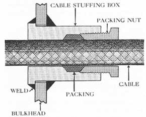
The "weak spot" of these pumps is at the point where the electric lead or cable passes through the watertight casing to the motor. The packing gland provided at this point should be carefully checked, together with the rest of the electric lead and connections. No one should ever be allowed to lift or handle the pump by its electric cable lead.
Each pump should be provided with a suitable length of 1/4-inch wire rope for lowering. If this is not readily available, a 50-foot length of 15-thread manila line, with a suitable length of 1/8-inch seizing wire
wound in the lay to provide strength if the manila burns or is cut through is recommended. The manila line is necessary to facilitate handling under adverse conditions when water and oil are present in varying quantities.
It usually is necessary to use more than one submersible pump to control flooding. For each pump in actual use it is wise to have another rigged and ready to drop into place. Electricians and other repair personnel should be kept at the scene, available for quick repair work when pumps fail. Portable electric cables capable of carrying the load of five pumps, and fitted with a five-receptacle jack plug, should be available for running more than one pump at a time. (See BuShips Bulletin of Information No. 13, page 30.)
221
CHAPTER XXX
MATERIAL UPKEEP AND DAMAGE CONTROL
30-1. Foreword. Control of damage is largely dependent upon measures taken preceding action to reduce and to localize the effect of hits. These measures include maintenance of:
1. Ship's watertight integrity.
2. Hull and engineering systems in their most efficient operating condition.
3. Damage control equipment in its most efficient operating condition.
In addition, a full allowance of essential damage-control materials must be kept on hand, in first class condition, and available upon short notice.
PRESERVING WATERTIGHT INTEGRITY
30-2. Subdivision. Every Naval vessel is subdivided by decks and bulkheads both above and below the waterline into as many watertight compartments as are compatible with the ship's mission. In general, the more minute this subdivision, the greater the ship's resistance to sinking after damage. A modern battleship has well over 600 watertight compartments. The condition of this subdivision, the watertight integrity, is of the greatest importance. It is determined in the beginning by the skill and thoroughness of the builders. They strive to make the boundaries of the subdivision strong and watertight in accordance with specified requirements.
This initial strength and watertightness may be reduced or destroyed through negligence, storm damage, collision or stranding, and, finally, by enemy action. It is a primary responsibility of the damage control officer to see that the ship's watertight integrity is not impaired through negligence, and that any damage to it, whatever the cause, is repaired as completely and as quickly as possible.
Bureau of Ships Manual, Chapter 29, Section II defines various standards of tightness and specifies the periodic tests and inspections necessary to attain these standards. In addition to watertightness there also are standards known as oil, air, and fume tightness. An oiltight boundary is watertight; the others are not.
30-3. Loss of watertightness: Loss of watertightness may result from:
1. Corrosion.
2. Loosening of boundaries or joints.
3. Defective closures or fittings.
4. Lack of care in making alterations.
Specific defects in watertight integrity may be caused by:
1. Holes in, or improper fit of structural members.
2. Defective fittings passing through boundaries (stuffing boxes and other bulkhead or deck fittings).
3. Defective piping, tubing, ventilation ducts, etc., passing from one compartment to another.
4. Defective condition of watertight closures involving doors, hatches, scuttles, manholes, ventilation covers, valves, sounding tubes, etc.
Corrosion, or rusting, is oxidation of metal caused by the combined action of air and moisture upon it. It is accelerated by the presence of salt in the moisture, and has a tendency to be increased where one metal is placed in contact with a dissimilar one. Corrosion weakens structures, boundaries, joints, piping and ventilation ducts. It hampers and causes defects in the operation of fittings. Because it reduces structural strength and destroys watertight integrity it must be guarded against.
Loosening of boundaries and joints can result from (1) the working of the ship in heavy weather, (2) shock of gunfire, (3) wracking of the ship by violent, high-speed maneuvering, and (4) vibrations set up by operating machinery. All of these tend to cause relative motion between adjacent structural members at riveted or welded joints. This may result in the loosening of caulked riveted joints or the cracking of welded joints. The former is the more likely, is harder to detect, and is more difficult to correct. Repairs to either riveted or welded structure must be made as soon as defects are discovered.
A riveted joint is not inherently watertight or oil-tight. This is because the surfaces or edges held together are not machined or ground. Such connections are made tight by means of calking. In calking, a thin fin of metal is sprung from the base plate or
222
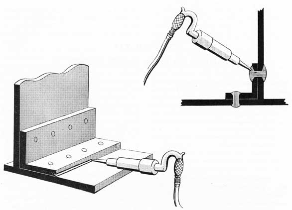
Figure 30-1. Diagram to illustrate calking of a bounding bar and a rivet.
structure by use of a chisel, usually pneumatically driven and called a calking tool. The accompanying illustration (fig. 30-0 indicates the general method of using calking to produce tightness.
30-4. Insuring watertight integrity. Closures and fittings which pierce watertight bulkheads and decks are all potential sources of leakage of the most serious nature. The points of weakness inherent in each of them must be carefully considered. Closures may be classified as follows:
1. Openings for access:
a. Watertight doors and hatches.
b. Quick-acting watertight doors and scuttles.
c. Watertight manholes, bolted plates, and covers.
2. Fittings permitting passage of essential ship's systems:
a. Ventilation ducts, closures, and valves.
b. Electric cable conduit and stuffing tubes.
c. Piping, tubing, valves, drains, sounding tubes, etc.
d. Solid rotating shafts.
Access closures may lack tightness because of faulty
gaskets. The gaskets are installed in doors, hatches, scuttles, and dogged manhole covers to provide a tight fit. However, exposure to oil, grease, heat, or coatings of paint will cause them to deteriorate. They should be inspected frequently; especially the gaskets located in machinery spaces.
Gaskets used with bolted manhole covers and similar bolted plates are of a different type, and should be made up in accordance with directions found in Appendix 9 of the General Specifications. These gaskets should be renewed if found in poor condition when a cover is removed. This is important because, once bolted down such a closure appears to be tight, whereas it actually may be a channel through which flooding will progress. It is necessary, then, that the gasket be of the proper material and in good condition when the cover is replaced, and that the bolts be set up tightly and evenly all around. Loosely secured covers have been blown off by explosions; tightly bolted ones have remained securely in place.
Knife edges and bearing surfaces may be distorted by the impact of heavy objects, as when ammunition or similar material is carelessly handled when passing
223
through doors and hatches. Ship's personnel must be trained to avoid handling heavy weights in such a way that this can occur. Damaged knife edges and bearing surfaces should be repaired immediately whenever possible. Navy yard or tender repairs may be necessary in cases of serious damage. Rust and paint must be kept from knife edges and bearing surfaces. The use of emery cloth on knife edges must never be permitted.
A common point of leakage is where dog spindles pass through door frames. There is a stuffing box for each dog spindle. These have packing inserted to prevent leakage, but this may deteriorate, loosen, and even come out. Frequent inspections should insure that these packings are in good condition and that the packing gland is properly tightened in the stuffing box. Dogs should be repacked when necessary for packing hardens with age. Dogs must also be adjusted occasionally to accommodate wearing down of the wedges against which they bear. In addition, wedges may have to be built up or replaced when badly worn.
Figure 30-2. Stuffing box (tube) used in passing electric cable through a watertight boundary.
For a door or hatch to be watertight when dogged the knife edge or bearing surface must be well centered on the gasket and must bear evenly and firmly all around. To accomplish this the door or hatch must be located correctly on its hinges in relation to the frame. Neither door (hatch) nor frame should be warped. Knife edges must be straight and even, retainer strips firmly screwed in place, and the dogs adjusted to provide equal pressure on all wedges when set up. Incorrect fit may permit the frame or knife edges to come into contact with metallic parts of the closure (retainer strips, etc.) and allow the door to be closed in a non-watertight condition.
Gasketed covers provided for the ends of ventilation ducts are subject to the same ills as access closures. Other types of ventilation closures and valves installed in the ducts are subject to lack of tightness caused by improper seating, dirt in ducts, corrosion, failure of operating gear, etc. Frequent inspection, operation, lubrication and routine upkeep are needed to counteract the effects of dirt and salt air on these fittings which are of many different types.
Electric cables pierce many watertight boundaries. Watertightness is insured by passing each cable through a packed stuffing tube as shown in figure 30-2.
A heavy concentration of cables frequently pierces a small area of a deck or bulkhead, forming a "nest" of cables and stuffing tubes. The cables and tubes nearest the center of the "nest" are very hard to reach and can be repacked only with great difficulty. This packing is most important for without it the cable provides an easy path for progressive flooding. Stopping such leaks after damage, when flooding already is in progress, is a most difficult and time-consuming job. (See BuShips Bulletin of Information No. 9, page 51 for information about electric cable packing tube-nut wrenches for reaching inaccessible stuffing tubes. See also Bulletin No. 6, page 30.)
Where piping pierces bulkheads and decks, possibility of leakage always exists. Such piping ranges in size from small copper tubing to large drainage mains. Various means are used to make penetration points watertight. Welding may be faulty due to piping coming through compartments in locations difficult of access. Here welders sometimes do not complete their welds, or else do rot make them sufficiently strong. Subsequent vibration, or working of the ship, acts to increase the defect. Also, where flanged connections exist, deterioration of the joints will permit leakage. Valves on piping terminating within a compartment (sounding tubes, deck drains, air piping, etc.) will leak if they are not in good condition. They must seat properly and tightly. If normally open, it must be possible to close them easily and tightly.
Solid rotating shafts range from small remote-control operating shafting to the large propeller shafting which drives the ship. In practically all cases these shafts pass through packing boxes (stuffing tubes) to provide watertightness of the boundaries they pierce. It is not a simple matter to maintain this watertightness, because rotary motion may wear or dislocate the packing. If the packing is too tightly compressed operation is difficult; if too loose, leakage will occur.
224
Alterations authorized by competent authority are for the purpose of improving the ship's fighting efficiency. Many of these alterations require additional piercing of existing watertight bulkheads. New electric cable and wiring, new piping and tubing, new ventilation ducts, etc., are required. Conversely, much old piping, wiring, etc., must be removed, and this necessitates the blanking of holes left in boundaries.
In such cases, each new fitting should be checked by the ship's force to he sure that it is properly installed and watertight. The blanking of holes following removal of obsolete wiring, piping, fittings, etc., should be followed up assiduously. Experience has proved that these precautions are necessary, regardless of whether the activity accomplishing the alteration is a Navy yard, tender, base, or own ship's force. It is particularly desirable that there be full intra-ship, interdepartmental cooperation, to insure that all possible points of weakness following alterations or repairs are carefully checked. (See BuShips Manual, Chapter 29, for directions concerning preservation of watertight integrity by yard forces upon completion of alterations or repairs. Follow these closely.)
One other source of potential impairment exists. It has to do with the tendency of ship's personnel to make unauthorized alterations. If unchecked, this tendency can lead to very serious results. It must be clearly understood by all hands, officers and crew, that nothing may be attached to or run through decks and bulkheads in any manner whatsoever without the express permission of the damage control officer. As stated in the Bureau of Ships Manual: "Holes or openings for any purposes whatsoever, except those shown or indicated by the plans and specifications, shall not be cut in any watertight bulkhead or deck without the approval of the Bureau." (Chapt. 11, Art. 11-26.) It is the responsibility of the damage control officer to see to it that this regulation is observed.
30-5. Tests and inspections. To insure that the ship's watertight integrity is rigidly maintained, a thorough system of inspections and tests is prescribed by U. S. Navy Regulations and the BuShips Manual (Chapt. 6). In the course of these tests, defects should be discovered and must be corrected immediately. There are three types of inspections, as follows:
1. Periodic tests and inspections to determine the complete status of the ship's watertight integrity. (See BuShips Manual, Art. 29-54 to Art. 29-62 re periodic watertight integrity tests and inspections).
2. Routine (weekly) compartment inspection by
ships' officers. These normally are submitted by division officers (Hull Reports; U.S. Navy Regulations, Art. 1360; BuShips Manual, Chapt. 6).
3. Semi-annual inspection of the ship by the hull board (U. S. Navy Regulations, Art. 1359; BuShips Manual, Chapt. 6).
There are three means of determining the condition of watertight boundaries and compartments when making periodic, watertight integrity tests and inspections. These are as follows:
1. Observation of oil and water leaks from tanks into adjoining spaces.
2. Visual examination.
3. Air tests.
30-6. Detecting oil and water leaks. Bulkheads and decks separating oil and water tanks must be inspected for leaks at least once every six months. Such leaks frequently are evident at rivet heads, poorly calked plate laps or stiffeners, and poorly calked bounding angles. Visible leaks should be calked or welded by the ship's force, when possible. Otherwise, a record should be maintained in the current ship's maintenance project for repairs by yard or tender when availability can be obtained.
30-7. Visual examinations. Some of the compartments listed in the periodic test schedule call for periodic visual examination. Or, if the ship has no such schedule, important watertight boundaries will be so listed by the Commanding Officer. This inspection is made by completely closing and darkening the compartment on one side of the boundary in question, stationing an observer therein, and intensely lighting the other side.
Compartments listed for this type of examination normally are incapable of being tested by air pressure, because of the presence of permanent openings to the topside; for example, engine rooms and firerooms. It is obvious, however, that they are extremely important parts of the ship's watertight subdivision, and deserve the most careful and scrupulous scrutiny. Visual examination (rather than air test) does not mean that the boundaries are unimportant. When inspection is visual it is highly desirable that different inspectors make successive periodic examinations, so that no defects will be overlooked repeatedly.
30-8. Air tests. When compartments cannot be filled with oil or water, the only practicable means of establishing the degree of watertightness is the air test. In this test the compartment is completely closed, and air pressure is built up. The loss in pressure. Or
225
"drop" over a specified period (normally ten minutes) indicates the degree of tightness.
Air pressure does not truly simulate the varying hydrostatic pressure placed upon a compartment's bulkheads when it is flooded, nor does it represent the flooded condition of water pressure, since the air test places the same pressure on the overhead and the deck. However, the air test remains the most satisfactory method of detecting leaks in watertight compartments on ships in commission.
For most Naval vessels a schedule of watertight integrity tests and inspections is issued by the Bureau of Ships, listing compartments subject to test or inspection, and specifying which type of test or inspection applies to each. Ships not provided with such a schedule are required to make inspections of important watertight boundaries in accordance with practices prescribed in this discussion and in the BuShips Manual, Chapters 6 and 29.
The watertight integrity tests and inspections schedule contains a list of compartments to be air tested, and indicates in each case the test pressure to be used and the permissible drop in pressure over a specified period of time. Every compartment designated for air testing in the periodic test schedule should be tested once every eighteen months. Compartments normally are divided into six groups. Each group is tested during a three-month period. Thus, each compartment is subjected to its air test within the 18-month cycle required by regulations.
Each compartment designated for air test is provided with an air-test fitting for connecting the air-test hose. Provision for this connection may also be made via sounding tube or air escape if the compartment involved is a tank.
The ship's allowance includes portable air-testing sets. Each consists of a base on which is mounted a reducing valve (reducing from 15 pounds pressure to a discharge pressure of 1 to 5 pounds), an intake valve, a relief valve and a mercury gauge, the latter being either attached to the set or provided separately. Mercury gauges are provided in place of spring (Bourdon) gauges because they are more reliable and more sensitive.
The specific steps in air testing a compartment to determine its tightness are as follows:
1. A visual examination is conducted. Visible leaks are repaired.
2. All regular closures are secured. If the bulkheads are pierced by any rotating shafts or other
moving parts, the packing devices provided are set up in order to hold the air-test pressure. They should be slackened following the air test.
3. The portable air-test outfit is hooked up to the nearest ship's air-test station and to the compartment's air-test fitting. The test pressure specified in the periodic air-test schedule is built up. The mercury gauge provided with the set is watched closely to see that the pressure is properly applied.
4. The intake valve on the portable set is closed, and the pressure in the compartment allowed to "settle" for 15 minutes. The intake valve is again opened until the specified air pressure is built up, and is then closed. The supply hose is disconnected, and after the specified time (normally 10 minutes) , the pressure drop is recorded.
5. Leaks of any size will be indicated by the hissing or whistling of escaping air, and should be marked and noted down for corrective action. If the allowable drop is exceeded after such leaks are repaired, the boundaries of the compartment, joints, fittings, and closures must be gone over with a soap solution. Bubbles are formed by escaping air, and indicate leaks. These leaks should be repaired as soon as they are discovered.
6. When conducting an air test station a man inside the compartment with a lighted candle. As he goes over places where leaks may exist, the effect of air upon the candle flame will reveal their presence. Further, a smoke smudge left by the candle will mark the spot.
When a compartment's air test is completed, comparisons should be made with the last air test of that compartment. Any loss in pressure during the 10-minute period noted, in excess of the allowable drop, indicates a deterioration of watertight integrity. If repairs are inadequate, the compartment test should be listed as "unsatisfactory." Reasons for this condition should be recorded and permanent repairs requested at the next Navy yard or tender availability. Every effort should be made by the ship's force at the time of the air test, however, to make the compartment "satisfactory."
A few precautions must be observed in connection with compartment air testing. Among them are the following:
1. In no case should the air-test pressure be exceeded. (Serious damage to structure and
226
boundaries of the compartment will result if this warning is disregarded.)
2. Be sure the cap is replaced on the air-test fitting when test is completed.
3. "Doctoring" a compartment for the purpose of passing the test is a definite hazard to the ship's future safety.
The rush to complete work on a ship toward the end of a period of availability at a Navy yard sometimes leads to the abandonment of air-test procedures. The ship's force should be alerted to the fact that survival after damage depends upon the ability of internal boundaries to hold back the sea.
In summarizing, the following instructions and suggestions regarding air testing are considered important:
1. When testing compartments the instructions found in the watertight integrity schedule must be followed.
2. Guard against using excess pressures.
3. Make certain that temporary closures are removed from overflows, air escapes, and air vents in magazines and fuel-oil tanks when an air test is completed. If these escapes are left closed the boundaries are sure to be ruptured when the fuel-oil tank or magazine is filled or flooded.
4. Electrical push buttons with leather diaphragm covers for actuating alarms or remote-controlled valves for sprinkling, flooding or counterflooding are installed in compartments on some ships. When pressure is applied to a compartment where these buttons are installed it will cause the diaphragm to be pressed in and contact will be made, initiating the function which the push button controls.
5. Detail competent personnel for conducting air tests and also for witnessing air tests made at Navy yards.
6. Check reducing and relief valves frequently on air-testing equipment.
7. Do not use spring gauges for recording pressure drop.
8. Insist that repair yards conduct an air test on all compartments where watertight integrity may have been impaired when making alterations.
9. Compartments which test "unsatisfactory" are a serious hazard and should be brought up to a passable standard immediately.
10. Repairs to compartments which are beyond the capacity of the ship's force should be noted in the current ship's maintenance project file and
obtained during the next Navy yard or tender overhaul.
11. On large ships it may be found advantageous to have a special watertight integrity repair gang working in coordination with each air-test gang, to insure that serious defects will be remedied promptly (and without fail) , and that minor defects, which in the aggregate are important, will not be overlooked.
30-9. Do not postpone repairs. Postponement of repairs until the next Navy yard or tender overhaul may find the vessel damaged first. Therefore, the maintenance of watertight integrity becomes a ship's force job of urgent importance.
All personnel charged with ship's maintenance are responsible not only for the condition of the ship at the time of a specified material inspection, but also for the performance of watertight boundaries at the time the ship is damaged. Attention of all hands can be secured by indoctrination of the ship's company in the need for proper upkeep. The job is inherently a continuous one, with results invisible until the ship is damaged.
30-10. Routine inspection by ship's officers. All compartments, with the exception of certain tanks and voids, are inspected weekly by an officer. The most convenient grouping for this inspection usually is according to division cognizance, and the inspecting officer submits his report on the material condition of the compartments inspected (as to cleanliness, state of preservation, condition of fittings, drains, etc.) to the Commanding Officer via the damage control officer and first lieutenant. The importance of these hull reports, submitted weekly, must not be underestimated. Conscientious inspections by division officers and their subordinates can bring to light visible defects in watertight integrity which might otherwise go unnoticed until the next air test. Submission of reports on watertight integrity defects should be encouraged and even solicited. Prompt acknowledgement and action upon such reports will develop an increased determination on the part of all hands to keep their ship in the best possible condition.
30-11. The hull board. Once every six months, a hull board appointed by the Commanding Officer of every Naval vessel inspects the ship and submits a report on the ship's material condition with particular regard to the deterioration of inner bottoms, fireroom bulkheads, corrosion of the hull between wind and water, and the underwater portion of the hull,
227
including valves, propellers, and rudder. In addition, the condition of the following items is the subject of inspection and report:
1. All parts of the topside.
2. All parts of the inner hull.
3. All accessible tanks and double bottoms.
4. Pumps pertaining to hull systems (fire, drain. age, etc.), including the results of operating tests.
5. Hull auxiliaries, such as anchor gear and steering gear, winches, etc.
6. Masts and rigging.
In concluding the study of watertight integrity, it must be emphasized that only by constant effort can this condition be maintained and maximum resistance to damage be realized. A loose ship is a leaky one, susceptible to serious progressive flooding from the type of damage that would be of relatively minor importance on a tight ship. The penalty for laxity in inspecting and correcting defects may well be a ship unnecessarily lost.
MAINTENANCE OF HULL
AND ENGINEERING SYSTEMS
30-12. Importance of hull systems. Preparing a ship to control damage successfully requires that vital systems be maintained in their best operating condition. Reliance will be placed on them; they must be dependable. They will not meet the desired standard if they are not kept in good operating condition by a well planned and alertly supervised program of preventive maintenance.
It is true that battle damage may destroy parts of any system, particularly in areas where that system is most needed. Sectionalization of individual systems can overcome this to a very marked degree. But if any one system cannot be depended upon to operate properly in an emergency the enemy has been given a definite advantage.
Hull systems have been discussed in Chapter XXIX. For present purposes we may note that each of them has the following functional divisions:
1.. A source of power (pumps, compressors, generators, blowers, etc.).
2. Means of transmission (piping, wiring, tubing, vent ducts, etc.).
3. Means of control (valves, closures, switches, regulators, etc.).
30-13. Planned maintenance programs. A planned maintenance program must neglect none of the foregoing divisions, or any part of any system no matter
how small. A little steel pin dropped out of position or sheared off can jam a rudder. A resulting collision might do more damage to two fine ships than a torpedo hit would. A similar accident could prevent closing a valve to isolate a damaged section of the fire main. Planned maintenance will reduce the probability of such accidents.
The fundamentals of a planned maintenance program are as follows:
1 Fixing individual responsibility for each system and for sections or functional divisions of each system.
2. Regular and frequent operation, testing, inspection and upkeep of all parts of each system.
3. Periodic reports of such operation, tests, inspections and upkeep, from individuals held responsible to cognizant heads of departments.
4. Immediate repair, renewal or replacement of parts which are found defective.
5. Reliable and adequate supply of spare parts and materials required for upkeep and repair.
6. Periodic "check" tests and inspections by supervisory personnel.
30-14. Fixing responsibility. The fixing of responsibility for any system and for its various components is the primary step in insuring that it will be properly maintained. This is not as simple as it sounds. On board most ships there frequently is an apparent overlapping of responsibility between engineering and hull departments. The gunnery department, too, is involved where the various systems come into or are attached to its installations. Chapter 5 of the BuShips Manual, entitled "Cognizance," should be studied and used as a guide in this matter.
At this point it is desirable to re-emphasize the extreme importance of the very closest liaison between the hull and engineering departments aboard any ship. Only in this manner can effective maintenance of hull and engineering systems be obtained. Indeed, the entire program for protecting the ship to the maximum possible extent from the effects of damage is mainly dependent upon such liaison.
When departmental (and divisional) responsibilities have been clearly defined, suitable individuals must be made responsible for the maintenance of each system or appropriate division of that system. In most cases such delegation of responsibility will follow naturally from the individual's shipboard assignment. Thus, responsibility for maintaining electric motors, wiring, and controls of any system would rest with the electrical officer. He, in turn, normally delegates and
228
divides this responsibility among his subordinates.
The damage control officer will do well to see that responsibility for proper maintenance of all systems or parts of systems for which he is responsible is suitably divided among and specifically delegated to those of his subordinates who are most capable and conscientious. He will also find it necessary to keep himself fully informed concerning the methods used (and results obtained) by other departments in keeping those systems in proper operating condition which do not come under his cognizance, but which are, nevertheless, essential for control of damage.
Quoting from Article 1360 U. S. Navy Regulations: "The (damage control officer and) first lieutenant, navigating officer and engineer officer shall inspect weeklyall mechanical devices for the management and safety of the vessel, for which each is specially responsible, and shall make to the Commanding Officer, after each inspection, separate written reports on the condition of the parts of the ship and of the mechanical devices thus inspected.-
30-15. Operation, test and inspection. The next step is to determine the required frequency of operation, test, and inspection for the functional divisions of each system together with its detailed parts. From such determinations detailed schedules will be made.
In determining how often to operate, test or inspect a system or portion thereof, the BuShips Manual should be consulted. In general, weekly operation and test schedules will be found satisfactory. For some parts of certain systems experience will demonstrate that monthly schedules will be sufficient. In, a very few instances a test operation or inspection once each quarter may suffice. Most inspection programs should be on a weekly basis. Only when such a frequency is shown to be unnecessary, and therefore wasteful of manpower, should the time interval between inspections be increased.
Such periodic operations, tests, and inspections, when conscientiously carried out, will bring into hold relief any inherent defects in a system. When these have been corrected, systems will operate more smoothly and require less maintenance. In addition, this type of maintenance program will show up many impending casualties which can be eliminated before they occur, merely through replacement of weak parts, lubrication of others, and strengthening of still others.
30-16. Require regular reports. Any planned maintenance program, such as that briefly outlined here, will not work well without suitable reports. The responsible directing officers must be able to ascertain
quickly and accurately the condition of their systems at any time, Further, the subordinates directly concerned must have a means of checking the proper operation of the program (and the equipment) by frequent recourse to such reports. Reports, however, can be ineffective if (1) it takes too much time to prepare them, (2) if they are too voluminous, or (3) they do not cover the essential points.
For these reasons, check-off list types of reports are recommended. On such forms the essential parts of a system are listed. Opposite each part is a column for initials and date to be inserted by responsible personnel when the operation, test or inspection is made. Another blank column is provided for recording action taken, defects noted, or other pertinent remarks. Such reports turned in periodically, in accordance with the proper time interval, can be quickly checked and conveniently filed. Each report should be signed by the responsible subordinate.
Time spent in planning and working up suitable report forms for a maintenance program will pay valuable dividends. A conscientious and prompt submission of such reports will create a justified feeling of confidence that the various systems will operate satisfactorily when needed. It will make a current knowledge of the condition and capabilities of each system readily available, not only to the cognizant department head, but also to those of his subordinates most concerned.
This type of maintenance program correlates very well with educational and training programs for "primary" damage-control personnel.
30-17. Upkeep and repair. The routine schedules previously mentioned must, of course, include lubrication and cleaning of the parts of the system, so that they may continue to operate satisfactorily until the next inspection, test, etc. But the maintenance program must provide for prompt correction of any defects discovered. This can be arranged by having the following actions taken:
1. Minor defects repaired on the spot by the test or inspection groups.
2. Less easily repaired defects reported immediately to proper supervisory personnel, who will have repairs made as soon as possible by the proper repair gang or individual.
3. Defects requiring major repair efforts but still within the capacity of the ship's force brought to the attention of the cognizant department head who will determine or obtain a suitable priority for the work.
229
If beyond the capacity of the ship's force, repair will be requested from a tender or Navy yard at the first available opportunity. Suitable entry is made in the current ship's maintenance project file whenever repairs are made or requested.
No effort must be spared, nor ingenious method overlooked, to effect emergency or partial repairs by the ship's force, even though eventual correct repair must come from a tender or yard. Systems must be kept in good operating condition if this is at all possible.
30-18. Adequate supply of spare parts and materials. Foresight plays an important part in a sound maintenance program. Time and manpower will not be wasted in simple repair and renewal work when an adequate supply of essential spare parts and repair materials is kept on hand. This includes normal upkeep materials such as lubricants, packings, etc.
It is not possible to have 100% of spares for everything on the ship. Nor is this desirable from a weight standpoint. Allowance lists are drawn up with this in mind. Intelligent thought must be given to the types and amounts of expendable materials to be carried. In deciding this, past experience (particularly that of subordinates trained in repair work), the advice and assistance of the supply officer, and other pertinent information from reliable sources should be utilized to the fullest extent.
An infallible system for obtaining replacements of materials and spares used in upkeep and repair work would be most desirable. However, liaison with supply personnel can result in establishing a system whereby requisitions are submitted immediately when the supply of materials drops to a certain point, or when spare parts are drawn from the storeroom. No detailed plan is offered here, but some system must be developed which will insure that materials and spares used are promptly replaced. It is also important that maintenance personnel know the current "on hand" status of necessary materials and spares, and where they are kept. For this, too, responsibility should be centered in one individual within each department.
30-19. Check tests and inspections. Frequent unscheduled tests and inspections by department heads and their key assistants will serve to check how efficiently the maintenance program is operating. Regularly scheduled maintenance operations will be more conscientiously carried out if all hands concerned know that check inspections may be expected at any time. Such check inspections, trials or tests need not take up too much time. They may be brief, should be
frequent, and need not follow any particular pattern. They may be held while at general quarters, during war cruising condition watches, or at any other times. Witnessing a routine test or operation may be classed as a check inspection.
MAINTENANCE OF
DAMAGE-CONTROL EQUIPMENT
30-20. Maintenance program for repair equipment. A reliable program is necessary to insure that all necessary damage-control equipment (and material) is on hand, available, and in good condition. It will follow the same principles previously outlined for hull and engineering system maintenance programs.
Repair-party officers should be made personally responsible to the damage control officer that their repair parties have all the equipment and material allotted them by the hull allowance list; that it is in good condition and properly stowed so that it may be quickly obtained when needed. They should be required to have equipment tested and operated on a weekly basis, submitting reports on standard forms provided them by the damage control officer.
Defects discovered should be repaired immediately by repair-party personnel. If they are unable to make certain repairs, the ship's repair facilities must be called upon promptly to do so. Prompt submission of requests for requisitioning equipment and materials which require replacement must be insisted upon. Inspection of one repair party's equipment by another party should occur frequently to supplement the reports received as well as the damage control officer's personal inspections. Modifications of the foregoing recommendations may be found desirable for various types of ships but the principles involved will still apply.
30-21. Operate equipment frequently. There can be no substitute for frequent operation of equipment to insure that it will work when needed. It is recommended that the following items be used or operated at least once each week:
1. Submersible pumps.
2. Gasoline handy billy fire pumps.
3. Electric tools, lamps, etc.
4. Air-driven tools.
5. Shallow-water diving equipment; hose masks.
6. Fire-fighting equipment.
Emergency oxyacetylene cutting outfits should be inspected very carefully each week, particularly to see that all parts are attached and in good condition. The stowage condition of repair-party equipment, with
230
regard to neatness, cleanliness, completeness and accessibility is a fair measure of the potential efficiency of any repair party.
In conclusion, it may be pointed out that much of the material presented here is not limited to upkeep for damage control purposes. The principles of maintenance apply with equal force to any equipment on board ship, for whatever purpose installed and without regard to cognizance.
A ship's very life and the lives of most of her crew may eventually depend on how well her watertight integrity is maintained and how well her equipment will function when most needed. An alert, well-trained group of men using vital equipment with assurance can keep a tight ship fighting in the face of devastating damage.
30-22. Notes on access openings. The following paragraphs are quoted from the BuShips Manual, Chapter 16:
"16-1. Rubber gaskets as used for watertight, weather-tight, and airtight purposes should not be painted. The metal-bearing edges which come in contact with the gasket should be kept bright and free from rust, grease, and paint. If these edges are of corrosion-resisting steel they should be wiped occasionally with an oily cloth and then polished, but the use of emery paper, steel wool, or other abrasives for cleaning corrosion-resisting steel is prohibited."
"16-2. The dogs, dog bolts, nuts, hinges, and hinge pins or other parts of watertight doors, hatches, manholes, and airports upon which the watertight security of vessels depends shall not be removed except for the purpose of repair or adjustment. The removal of these parts for other purposes, such as cleaning or polishing, or making access temporarily more convenient, is prohibited, as this practice often results in the loss of the parts or results in their replacement without being correctly adjusted, thereby introducing a menace to the
watertight integrity of the vessel. Polishing of galvanized fittings such as dogs, dog bolts, nuts, hinges, etc., with emery paper or other abrasives is prohibited as this destroys the zinc coating and accelerates corrosion."
"16-2. The threads of dog bolts shall not be polished with files, emery, or sandpaper, as this practice in time wears away the threads causing too loose a fit between the bolts and nuts. Composition and corrosion-resisting steel bolts require only that they be wiped off occasionally with an oily rag or waste. Steel bolts, if kept clean and slightly slushed with heavy grease, will not rust."
"16-4. The foregoing instructions in regard to avoiding use of paint on gaskets apply also to gaskets as used in manholes and hatches for oiltight purposes. In setting up oiltight gaskets, care should be taken to see that these are in suitable condition for obtaining tightness in accordance with the instructions in Chapter 95.-
"16-5. When setting up dogs on watertight doors, hatches, etc., a dog on the opposite side from the hinges should first be set up with sufficient pressure to hold the door, hatch, etc., closed. Two dogs should then be set up snugly on the hinge side, after which all the dogs should be set up evenly to insure a bearing all around. When loosening dogs in watertight doors, hatches, etc., those dogs nearest the hinges should he loosened first; this prevents the door from springing and makes it easier to operate the remaining dogs."
"16-6. If the door, hatch, etc., is in good condition, it should only be necessary in order to obtain tightness that there be an even bearing all around. This bearing should be obtained by setting up dogs firmly and evenly all around, beginning as instructed above. Dogs should not be driven down. The necessary tightness should be obtained by setting up a little on one after the other, successively, until all are down firmly."
231
CHAPTER XXXI
REDUCTION OF FIRE HAZARDS
31-1. Foreword. It has been demonstrated repeatedly that steel ships can become floating furnaces, fed by fuel consisting of combustible materials carried aboard them. Some of our ships have become blazing infernos which had to be abandoned or (later) sunk by our own forces because fires got out of control and prevented the effective application of damage-control measures. The prevention as well as the fighting of fires has proved to be such a vital factor in the survival of a ship in battle that unremitting efforts must be made to reduce damage by fire through keeping hazards at a minimum.
The harm done by a fire is in direct ratio to its magnitude. It is only the very smallest of fires which can be extinguished without concurrent damage to electrical equipment, wiring, machinery, stores, or even the ship's structure and equipment. Flames, smoke, heat and salt water are all destructive.
The problem of preventing serious fires through intelligent reduction of fire hazard requires that certain steps be taken, as follows:
1. Eliminate all non-essential combustibles.
2. Replace, wherever possible, combustible materials and equipment with less inflammable items.
3. Limit to a practicable minimum amounts of essential combustibles carried.
4. Stow and protect all essential combustibles so as to reduce the probability of their causing or contributing to destructive fires.
5. Maintain the ship in its best fire-resistant condition by:
a. Making regular and frequent inspections.
b. Educating all personnel with respect to reduction of fire hazards.
c. Establishing and enforcing sound shipboard fire-prevention policies and practices.
31-2. Elimination of non-essential combustibles. ALL COMBUSTIBLE MATERIAL NOT NECESSARY TO FIGHT THE SHIP MUST BE REMOVED, AND KEPT OUT OF OUR SHIPS.
Most Type Commanders have issued standard strip ship bills which direct the removal in whole or in
part of many combustible materials. Such bills should not only direct the removal of combustible materials, but also forbid the return of such materials aboard. Vigilance and alertness are required to prevent re-accumulation of fire-hazard materials and equipment on board any ship.
Unnecessary inflammable liquids should be eliminated. These include such materials as paints, varnish, shellac, lacquer, paint remover, paint thinner, turpentine, linseed oil, petroleum spirits, cigarette-lighter fluid, hair oil, shaving lotion, furniture polish, and inflammable brightwork polish. Any inflammable liquid which is not essential to fighting the ship should be included in the above list.
Current instructions to all types of combatant ships (aviation paint for carriers, seaplane tenders, and tankers only excepted) direct that "No-paint shall be carried aboard ship while at sea." Paint, in its liquid form, is inflammable, and is not needed at sea. Arrangements have been made at even the most advanced bases to supply paints and paint-spraying equipment to ships which need them.
Unnecessary wood must be kept out of our ships. Damage-control lumber (shores, wedges, leak stoppers, etc.) is the only wood that should be on board. The shoring timber should be impregnated with a fire-retardant compound. If this is not possible, shores may be painted with fire-retardant paint. All other wood or wooden articles present a double threat: (1) fire hazard to the ship, and (2) splinter hazard to personnel.
Combustible deck coverings cause stubborn fires and much smoke. Therefore carpets, rugs, linoleum, rubber, and cocoa mattings should not be on board, with the exception of certain items near electrical equipment. The Commanding Officer of one of our carriers reported: "the rubber matting on the deck burned fiercely." Personal comfort of officers and crew should be considered only when it contributes directly to fighting efficiency, the ability to survive, and the safety of the ship.
232
Combustible luggage, such as trunks, boxes and suitcases should not be aboard. Officers and men who bring such luggage aboard when reporting to the ship should be required to dispose of it immediately. Clothing and other personal effects, both of officers and enlisted men, should be held to the minimum required kr life aboard ship under existing operating conditions. Clothing should be stowed in metal lockers. Unseasonable or spare clothing should be stowed in compartments well below the waterline. Fire-resistant canvas bags or metal boxes may be used for this purpose. The Commanding Officer of one cruiser, ultimately lost by capsizing reported: "Fires, particularly the one in the wardroom country, were the direct cause of the loss of the ship."
To anyone who has not experienced the extremely difficult and harassing conditions imposed by a fire fed by upholstered furniture, excess clothing, excess material in living spaces, etc., the various Fleet and type instructions directing the elimination of such items from a ship may seem unnecessarily stringent. Responsible officers must not permit themselves to be lulled into a false sense of security by their good fortune in not having to cope with such serious situations.
To summarize, for each ship there is a strip ship bill, based on instructions issued by the Type Commander, directing the elimination or reduction of the following kinds of combustible materials:
(Materials to be removed from ships)
1. Cork insulation.
2. Dress uniforms.
3. Overstuffed furniture and cushions.
4. Linoleum.
5. Wooden furniture.
6. Wooden tables and benches.
7. Trunks and suitcases.
8. Brightwork polish (inflammable).
9. Furniture polish.
10. Linoleum wax and cement.
11. Calcium phosphide pots.
12. Awnings and awning stanchions.
13. Cane fenders.
14. Wooden grating and battens.
15. Wooden accommodation ladders.
16. Rugs and carpets.
17. Stage planks for side cleaners.
18. Excess cordage.
19. Excess blocks and tackle.
20. Dressing lines.
21. Cloth curtains (combustible).
22. Excess cots.
23. Paints, varnish, shellac, lacquer, etc.
24. Paint remover and paint thinner.
25. Turpentine, linseed oil, petroleum spirits, etc.
26. Excess alcohol.
27. Excess lubricating oils and greases.
28. Paint brushes.
29. Cigarette lighter fluid.
30. Excess kerosene and gasoline.
31. Wood or paper boxes and cartons.
32. Office files and records not in current use.
33. Personal correspondence.
34. Newspapers and magazines.
35. Excess books.
36. Excess stationery.
37. Cocoa matting.
38. Rope fenders.
39. Bulletin boards (combustible).
40. Canvas (not fire-retardant treated).
41. Chair and transom covers.
42. Weather screens and ladder screens (not fire-retardant treated).
43. Hose covers.
44. Rubber matting.
45. Paint on interior bulkheads and overheads (excess).
46. Linoleum.
47. Compressed gases (excess).
48. Excess bunting and flags.
49. Hair oils and shaving lotions.
50. Celluloid soap boxes.
51. Lumber not required for damage control.
31-3. Replacement with incombustible items. Items normally made from combustible materials can frequently be replaced by similar items fabricated from incombustible or less combustible materials. This may cause certain inconveniences, but such inconveniences are part of the purchase price of protection from serious fires. For example, the following possibilities may be noted:
1. Old-type canvas should be replaced by the new fire-retardant treated canvas. More of this will be available as time progresses. Kapok life jacket covers are being fire-retardant treated before delivery.
2. Glass cloth is in use for curtains and door coverings. This material will eventually come into a much wider distribution.
3. Glass fiber and block insulating material has replaced cork. Glass cloth is used in place of canvas for covering insulation.
233
4. Fire-retardant paints are now in general use, replacing the older types of inflammable paints. The liquid paint will burn, but when it is sprayed on in a thin coat and has thoroughly dried it is relatively non-combustible. One ship recently reported after a fire caused by a bomb hit: "Fire retardant paint functioned well - none burned."
5. Wooden mess tables and benches are being replaced by metal furniture. Ultimately all wood furniture should be replaced by metal. This is also true of wood gratings, battens, bulletin boards, stowage boxes, gangways, brows, etc. There are very few wooden articles which cannot be satisfactorily replaced by metal or plastic.
6. Incombustible deck coverings have been developed following linoleum elimination. One satisfactory type has been the "emery cloth" type, usually laid in small individual pieces as deck treads. For deck areas where traffic is not particularly heavy, and where non-skid characteristics are desired, a light-weight abrasive deck covering (Ferrox type), sprayed or trowelled on to the deck, has given satisfaction. It must be carefully applied and thoroughly dried before use. Other deck areas should be painted with fire-retardant deck paints, as required in Appendix 6 of the General Specifications.
7. Navy motion picture training film is now relatively safe. However, the film used for entertainment is highly combustible and should be carefully safeguarded.
31-4. Limiting the combustibles carried. There are many combustible materials needed to operate and fight our ships, which can neither be eliminated nor replaced by less combustible ones. The very value of some of these, in fact, lies in their combustibility. An adequate amount of each must be carried for use when need arises. However, amounts carried must in every case be limited to that which will actually be required for the operations contemplated. These amounts must be determined from the best knowledge and experience available aboard each ship, and in accordance with Fleet and type directives.
Some examples of necessary combustible materials are as follows:
1. Lubricating oils and greases are highly combustible but indispensable. Current directives state that ships will carry not more than a three month's supply.
2. Paper and office supplies will burn fiercely. These are also limited to not more than three
month's supply, but careful consideration should be given to even further reductions.
3. Files and records not actually needed for immediate reference should be placed ashore. "Fires immediately broke out in adjoining office spaces" runs the report from one carrier which was lost.
4. Pyrotechnics are dangerous fire hazards. Allowances must not be exceeded, and only those known to be required for the anticipated operation should be kept in the ready locker.
5. Gasoline (for ships without planes) is limited (for each type of ship) to amounts actually needed to operate gasoline-driven fire pumps in emergencies.
6. Alcohol. The amount carried should be limited sharply by needs.
7. Kerosene should be carried only in the very smallest quantities. Ships carrying Diesel oil have dispensed with kerosene entirely.
8. Cleaning supplies, such as soaps, soap powders, rags and waste are usually carried in excess. "Repair parties extinguished the fire in the rag stowage in about one hour, except for some baled rags which smoldered for about two days" was the report from one vessel.
9. Topside gear, such as cane fenders, wooden stages, manila lines, and blocks and tackles tend to accumulate. Strict control must be exercised over the amounts of these items on board.
10. Paint. In addition to directives that no liquid paint be carried on board the ship while at sea, the amount of paint carried on the ship's surfaces must also be kept to a minimum. Existing directives limit paint application on interior surfaces to one priming coat, covered by one coat of fire-retardant paint.
Limitation of the combustible materials carried on board any ship inevitably calls for interpretation of directives covering the amounts actually required. Fleet and type directives should be followed closely.
Analyze present requirements, past consumption, and possible future needs of each material which presents a fire hazard by its presence on board. Strict enforcement of the limitations indicated by this analysis will contribute greatly to the successful reduction of fire hazards.
31-5. Stowage and protection of essential combustibles. Proper safe stowage of combustible materials, and protection of those which cannot be safely stowed are most important to fire prevention. A
234
complete knowledge of the ship, an understanding of the principles involved, and the following of type directives will help to obtain the maximum amount of protection from fires.
The fundamental principles involved are as follows:
1. Keep the area above the waterline, including weather decks, as free from exposed combustible materials as possible. In particular, combustibles must be kept as far as possible from machinery space ventilation intakes.
2. Compartments below the waterline, near the shell (bottom or side) of the ship are considered the safest spaces for the stowage of combustibles.
3. Combustible materials which must be left in spaces above the waterline should be protected by enclosing them within metal lockers, tight metal containers, fire-retardant covers, or similar protectors.
Each Type Commander's directive, concerning fire-hazard reduction embodies the above principles. A few examples will suffice to illustrate their application:
1. "Provide space well down in ships for inflammable and unseasonable equipment."
2. "Alcohol in five gallon tins. Stow below the waterline."
3. "Gasoline. Use only the approved type safety container for stowing and transporting gasoline about the ship. To prevent occurrence of gasoline vapors, appliances should never be filled in confined areas."
4. "Gasoline for use in handy billy pumps ma9 be stored in approved 5-gallon safety cans well below the waterline. Combustible medical supplies such as ether, etc.,-Except for that amount used daily, stow - - - below the waterline."
5. "Lubricating oils and greases. Stow below the waterline in a space protected with a carbon-dioxide smothering system, when possible. The practice of stowing oils and greases in unauthorized areas (clipping rooms, ready service lockers, gun-repair lockers and telephone boxes) for convenience, should be discontinued and discouraged."
6. "Stow inflammable food oils, matches and inflammable medical stock in storerooms below the waterline."
7. "Stow spare gas masks in metal containers below the waterline. Place gas masks and flameproof clothing at battle stations, as far as practicable."
8. "Reduce officer's and men's personal effects
to essentials. Remove trunks and boxes and stow unseasonal equipment below the waterline."
9. Stow all library books, except a small number in use below the waterline."
10. "All drums of gasoline, kerosene and lubricating oils stowed on main deck are to be landed. The limited amount specified - - - shall be stowed in the paint locker." (Very recent destroyer directive.)
Insofar as practicable, when provisions and stores are received aboard they should be unboxed immediately prior to stowage in below-deck storerooms. This eliminates at once a large quantity of highly combustible material in the form of wooden or cardboard containers, barrels, crates, excelsior, and paper. Immediate unboxing of stores and provisions presents no particularly difficult problem if properly organized. Disposal at sea does. Such material cannot be thrown overboard, and burning it in the incinerator is a lengthy and onerous task often accompanied by the presence of smoke.
In line with this, it is most advisable to provide stowage below the waterline for all paper supplies, stationery, files, records, toilet paper, etc. At sea, only a small amount of the most vital correspondence files and records should remain in offices. Where practicable, establishment of a file room below the waterline is recommended.
The principle of stowing combustibles in compartments below the waterline, near the ship's shell, has been vindicated by war experience in which such compartments, when damaged, were quickly flooded. The incoming water effectively extinguished incipient fires.
All argument against this procedure is based on (1) the inaccessibility of below-deck stowage in action, and (2) the possible loss of an entire supply of essential material (gasoline for handy billy pumps is an example). Answers to such arguments are that (1) the immediate safety of the ship is the first consideration, and (2) a number of widely separated below-the-waterline stowages may be provided. Lack of easy access must be accepted in preference to providing additional fuel for topside fires.
Where topside stowage of inflammable liquids cannot be avoided, provision for quick or automatic release should be made. Such stowage should be as far aft as possible to prevent smoke and flame from interfering with the operation of ship and fire-control stations.
To protect combustible materials which cannot he removed from above the waterline spaces, proper
235
stowage and limitation of quantities are of the utmost importance. Additional excerpts from type directives are quoted as follows:
1. "All retained papers (files and records), books, publications, etc., should be stowed in closed metal stowages where practicable."
2. "Fit all metal trash containers with covers and attach them to containers with safety chain to prevent losing or misplacing. All trash cans should be kept covered."
3. "Provide fire-retardant covers for all berths throughout the ship."
4. One cruiser reported, "The flame-proofed bedding bags in living compartments definitely prevented bedding from catching fire from flash, short circuits, or fragments."
5. "Strip officer's quarters as ordered by the Commanding Officer in consideration of prospective operations."
6. "Remove inflammables from: (1) boiler spaces, (2) fire-room air intakes, (3) engine-room air intakes."
7. "Carry minimum amounts of lubricating oil and greases. Small amounts of these should not be kept in upper locations about the ship for convenience."
8. "Cover bedding stowages with flame-proofed canvas."
31-6. Maintenance of fire-resistant condition. Keeping the ship in its best condition to resist fire requires an alert shipboard organization. The organization must insure that (1) regular and frequent inspections are held, (2) personnel are educated to recognize and to control fire hazards, and (3) the policies laid down for their control are strictly enforced.
The damage control officer is responsible to his Commanding Officer for the foregoing, as provided for in the ship's damage-control organization. However, the problem of combating fire involves every department, every individual and every part of the ship. The coordination of all fire-prevention and fire-fighting activities on the ship is a necessary feature of a good organization.
As a first step in obtaining such coordination, it is highly recommended that one responsible officer or petty officer be designated as the ship's fire-protection officer. He should be a member of the damage-control organization, and a man whose experience and training particularly fit him for this assignment. One of the fire-protection officer's most important duties
is to conduct frequent inspections to see that existing instructions concerning fire-hazard elimination are being observed. He should consult with department heads and their key assistants, and with division officers, so that an efficient, harmonious operation of the fire-prevention program may be assured.
A detailed set of instructions, outlining the ship's policy on the elimination of fire hazards in accordance with existing directives and published over the Commanding Officer's signature, is of great assistance to the fire-protection officer in the performance of his duties. It also gives all responsible officers and key petty officers a clear understanding of what is expected.
In his inspections the fire-protection officer must be alert to discover possibilities for further reduction or elimination of fire hazards peculiar to his own ship. He should supervise education and indoctrination of the ship's company in fire prevention and fire-hazard control, as well as training in the use of fire-fighting equipment.
The activities of a ship's fire-protection officer in this direction will not attain their greatest potential results unless backed up and enforced by the continuing active interest of the Commanding Officer, executive officer, damage control officer and all other heads of departments. Quoting again from type directives:
1. "It has been found that daily inspections and strong measures are necessary to make all hands 'fire conscious.' "
2. "Keep all blowers, vents, and air ducts free of trash and dirt. Stow no combustible material near air-ventilation intakes and fans."
3. "The following serious fire hazards have been observed on a large number of ships - - (1) excessive amounts of gasoline, alcohol, Diesel oil, kerosene, lubricating oils and greases improperly stowed about the ship; (2) baled rags stowed in muffler spaces and boiler uptakes, and about the ship."
4. "Constant vigilance, periodic inspections, and the full cooperation of all hands are the only possible means of keeping ships of the Fleet in a high state of readiness to prevent destructive fires."
5. "The safe handling and storage of gasoline is of prime importance. Selected gasoline handling and storage crews should be indoctrinated and trained to assure constant vigilance and observance of precautions. Safety precautions should be prominently displayed and frequently published."
236
6. "Inspect all ventilation ducts at regular intervals and clean as necessary. Chemical analysis has shown dust accumulation to be highly combustible." (See BuShips letter S38-1 (638688-250-505) (C/L32 of 14 July 1943).)
7. "By immediately disposing of all packing materials as items are unboxed and inspecting the ship for cleanliness afterwards, the fire hazard thus involved is greatly reduced."
8. "It must be borne in mind constantly that fire is still the chief cause of damage to our ships and that any item overlooked in its prevention may have serious consequences."
9. "Ship's officers should request the services of Fire Fighting Consultation and Advisory Service on any fire-fighting problems." (Ref: BuShips letter S93-1 (688) EH28/A2-11 of 18 June 1943.)
10. "Regulations regarding smoking should receive careful consideration to insure that smoking is confined to suitable areas and is properly control led."
11. "Inspect all blowers, vents, and air ducts, particularly those in galleys, and remove trash and dirt."
12. "Maintain covers on all lights in hazardous spaces such as magazines, handling rooms, and spaces surrounding gasoline tanks or containing gasoline piping."
13. "All trash cans shall be emptied frequently, and never allowed to become full to overflowing."
14. "Good house-keeping conditions are essential to fire prevention. Daily inspection to ascertain whether these are carried out should be made by division officers as well as by the damage control officer and first lieutenant."
15. Oily waste is subject to spontaneous ignition and should be deposited in a self-closing waste can after it is used, and the contents of the can disposed of daily.
It is evident from the foregoing that elimination of fire hazards plays an important part in shipboard routine. The countless details involved can be observed only if a workable organization exists and is alertly used. In the final analysis, awareness of elementary fire-prevention principles and loyal, industrious application of them will best prepare our ships to resist fire.
31-7. Fire-resistant materials. The following list indicates the BuShip's ad interim specifications for fire-resistant paints and materials. These specifications are temporary, and are subject to change as new developments take place. When new specifications are received, either correct this list or prepare a new one. Reference: BuShips ltr. S93-(1) (350); EN28/A211 of 26 May 1943.
32-1. Foreword. Whether a battle casualty results from bomb, torpedo or projectile hit, fire is a common result. Unless the fire is quickly extinguished, more serious damage than that caused by the initial explosion may develop. Fire may cause the loss of a ship, even after other battle damage has been repaired or minimized. That happened to the LEXINGTON in the battle of the Coral Sea. Even though fire hazards have been reduced by stripping and clearing the ship there still remain substantial amounts of combustible materials on board.
32-2. Fire-fighter's schools. The Navy Department, therefore, has established fire-fighter's schools at various places for the purpose of training personnel in the use of the fire-fighting equipment found on board their ships.
At these schools students are given actual practical training in extinguishing fires. The instructors at the schools are all experienced fire fighters. All damage control officers should attend fire-fighting schools. They should endeavor to have as many officers, petty officers, and non-rated men as possible attend also whenever the opportunity presents itself. No one should lose sight of the fact, however, that despite efforts to simulate realism, instruction and drills at fire-fighting schools are given under relatively favorable conditions. At such schools there is a reliable source of water pressure, hatches and doors are not jammed shut, and access is not too difficult. In a shipboard fire resulting from battle damage, all of these obstacles, and more, may exist.
Each ship is equipped with the latest and most modern equipment for combating fires. However, the machine is only as good as its operator and his confidence in its effectiveness. Unless an operator has actually seen the equipment in use, and knows its potentialities through personal experience, he cannot hope to make the best use of it himself.
Practically all ships have motion picture projectors and films demonstrating the use of fire-fighting equipment. These films should be shown to all hands at regular intervals, supplementing the instruction given at the schools.
32-3. The Fire Fighting Manual. The Fire Fighting Manual was compiled by a staff of expert fire fighters. It is now a standard publication, issued by the Bureau of Ships. It contains descriptions and sketches of all types of fire-fighting equipment, and instructions for its care and preservation. The illustrated "type situations" listed on page 105-120 should be studied carefully. They will serve as models from which training problems may be developed.
FIRE-FIGHTING EQUIPMENT
32-4. Fire-main fouling. It has been found that the fire mains on ships are subject to fouling, especially because of the attachment and growth of marine organisms similar to those found on a ship's bottom. The marine growth will build up in a pipe, decreasing its effective inside diameter and reducing the amount of water that it can supply. Six-inch fire main pipes have been found with an effective inside diameter of only 2 1/2 inches, a reduction in discharge capacity of over 80 per cent. The growth will also accumulate on valve seats, discs, and stems, preventing proper operation of the valves. Small particles of this growth, loosened by shock such as that produced by gunfire, may also clog small orifices in the fog nozzles and sprinkler systems.
To limit the development of this marine growth, certain fire mains are coated on the interior with a plastic anti-fouling paint. This has to be applied in a Navy yard where special equipment is available. When new sections are added or old piping replaced, the new sections should be properly coated with this plastic.
Fouling can be removed in part by flushing out individual fire-main risers under full fire-main pressure. This is accomplished by using lengths of hose attached to fire plugs and leading them to the weather deck. Sufficient plugs must be opened simultaneously to insure that a large quantity of water passes through the larger pipes and dislodges as much of the marine growth as possible. Flushing should last for about five minutes and should be done weekly.
Marine growth can be killed by filling the fire-main system with fresh water (after all of the salt water has
238
been removed) because the marine organisms in question can not live except in salt water. However, this can be accomplished only when a ship is alongside a pier that has fresh-water connections. The job is done in the following manner:
1. Secure the fire pumps.
2. Open all sectional control valves.
3. Drain all fire-main piping.
4. Close drains and fill system with fresh water, flushing the 'risers from the highest fire plugs.
5. After allowing the fresh water to stand in the pipes for at least 24 hours, flush the mains and risers thoroughly.
To prevent stoppage in the small openings of fog nozzles and fog heads, a self-cleaning strainer is installed on each fire plug. The strainer collects foreign matter and may be flushed by operating a lever attached to it. (See the Fire Fighting Manual, pages 13-14.)
32-5. Weekly fire-main inspection. Fire-main valves may become inoperative due to bent valve stems, defective reach rods, or missing valve wheels. Fog and sprinkler heads may become clogged by verdigris or through careless painting.
A weekly inspection schedule for the entire fire-main system should be a fixed policy of each ship. All operating gear should also be inspected weekly. Each valve should be opened and closed, and the tell-tales checked. On distant control rods or flexible cables it is essential that the tell-tales be checked. This can be accomplished by closing a valve and adjusting the tell-tale pointer to read "closed" on both the distant control rod operating wheel and the valve operating wheel. Inspect for paint on the threads of valve stems, for workers are not too particular where they spray paint. Inspect the pins on the distant control gear, for a pin may be sheared, allowing an indication that the valve is opened when it actually may be closed. A good method is to peen the end of the pin to prevent it from falling out. At least one valve should be further inspected each week by lifting the valve bonnet. The interior of the pipe around the valve can then be seen. Check the valve seat for scoring. It is possible for the disc to be scored or the valve stem to be corroded.
The fire main should be further tested weekly by putting full fire-main pressure on the system and opening two or more fire plugs. The pressure on the fire main (as shown by the pump pressure gauges) should not fall below the pressure authorized. The relief valves should be tested by building up the pressure to
the relief valve setting and inspecting to see if they actually relieve the pressure. A recent directive calls for removing all relief valves other than those at the pumps, and for the installation of "leak-off" lines on the discharge side of centrifugal pumps in place of relief valves.
32-6. Testing the sprinkler system. All sprinkler systems are controlled by sprinkler valves. On larger ships these valves usually are electrically or hydraulically operated, so that they may be operated at the valve or from distant control stations.
In order that the sprinkler valve may be tested without sprinkling the space which it serves, a test casting is installed in the sprinkler line at the control valve. This casting has a flapper valve which may be locked shut by driving a steel wedge bar (known as a "gag") into an opening behind the valve. A pipe tee with a hose fitting is installed between the sprinkler valve and the test casting. In the latest design of test casting a hose fitting has been made part of the casting itself. To test the sprinkler valve, remove the cap from the test casting and insert the wedge bar. Remove the cap from the hose fitting on the tee. Attach a length or two of cotton rubber-lined fire hose or wash deck hose. Lead this hose to a scupper or over the side. Then test the electric or hydraulic operating gear at the valve. Follow this by disconnecting and testing the hand-operating gear. Connect up again and test from all distant control stations. As the valve operates each time, water will discharge through the hose. Finally, make sure that the control valve is shut, remove hose and wedge bar and replace both caps. Wedge bars should be kept under lock in the custody of the Commanding Officer.
The sprinkling piping should now be cleared by blowing compressed air through it. Remove the pipe cap at the end of the line to allow rust and scale to be blown out. Run a small piece of wire through each hole in the sprinkler lines and also through the orifices in the sprinkler heads to dislodge any possible clogging matter.
A system similar to a sprinkling system, known as a fixed fog system, is installed on some vessels. It does not have sprinkling valves, and is not directly connected to the fire main. Water must be supplied by connecting a length of hose from a fire plug in the vicinity to the system when needed. This system is installed in certain spaces that contain serious fire hazards. The compressed-air test should also be applied to fixed fog systems, and the fog-nozzle orifices should
239
be tested in the same manner as previously described for sprinkling systems.
32-7. Fire hose and nozzles. Fire hose, which is fully described in the Fire Fighting Manual, is supplied in 1 1/2-inch and 2 1/2-inch sizes for use on fire plugs and with foam equipment. It is double jacketed, cotton, rubber-lined hose, and is made in 50-foot lengths with a coupling at each end. One 50-foot length of 4-inch cotton, rubber-lined hose is furnished with each eductor with the Model P-500 pump, and is used on the discharge side of the eductor when it is employed for unwatering purposes.
Wire reinforced rubber suction hose comes in 2 1/2-inch size for use with the submersible pumps, and 2-inch size for use with the gasoline-driven handy billy pumps. Four-inch hard rubber suction hose is used for the suction of the Model P-500 pump.
Cotton, rubber-lined, and rubber hose should be kept in clean condition by careful handling. It should not be washed, except when the cover becomes oily or greasy (these materials will affect the rubber in the hose) and then only fresh water and a mild soap with a soft-bristled brush should be used. Never use wire brushes, holystones or caustic soap. Ordinary paint should never be used on hose, but a special water-soluble paint is used on weather-deck hose for camouflage purposes. After use or washing, hose should be dried at ordinary temperatures. Never dry hose at high temperatures because this practice tends to harden the rubber lining.
The types and number of hose nozzles for each ship is shown in its hull allowance list. These nozzles and their uses are described in the Fire Fighting Manual. Types of nozzles used are as follows:
1. All-purpose nozzle, equipped with fog applicators.
2. Chemical foam nozzles (plain tip).
3. Mechanical foam (NPU) nozzles.
32-8. Foam generators. Six types of foam generators are used on Naval vessels for the production of chemical and mechanical foam. Three of these produce chemical foam. The continuous type generator, portable or installed, uses foam powder, and is referred to as the "hopper type." It is described in the Fire Fighting Manual, pp. 26-27. The accumulator or pressure operated generator also uses foam powder. (See Fire Fighting Manual, pp. 28-29.)
The twin 20-gallon unit is described on pages 30-31 of the Fire Fighting Manual. It should be noted that both the accumulator and the 20-gallon unit are now being replaced either by continuous chemical foam
generators or mechanical foam pressure proportioners.
Duplex pressure proportioners (Fire Fighting Manual, pp. 32-34) use a liquid known as mechanical foam (type 5 charge) for which the NPU type nozzle is employed. Mechanical foam can be produced in the following ways:
1. Using the mechanical foam nozzle with the duplex pressure proportioner as shown on page 34, figure 30, of the Fire Fighting Manual.
2. Using the pick-up tube of the mechanical foam nozzle as shown on page 35, figure 32, of the Fire Fighting Manual.
3. Using the pick-up tube on the gasoline-driven handy billy and the mechanical foam nozzle as shown on page 36, figure 33 of the Fire Fighting Manual.
Foam, powder or liquid, should not be stowed in the weather or in excessively hot spaces as it will deteriorate. If powdered foam is stowed in the open, cans will rust and the powder will absorb moisture and become lumpy. These lumps will plug the small orifice in the generator. A locker or rack from which the cans may be quickly removed is desirable for stowage of foam containers. Liquid foam also must be protected from freezing.
32-9. Carbon-dioxide systems. The following means of using carbon dioxide as a fire extinguisher on Navy ships are provided:
1. The 15-pound capacity portable extinguisher.
2. Built-in systems, using 50-pound capacity carbon dioxide cylinders.
3. Hose reel units, consisting of two 50-pound capacity carbon-dioxide cylinders connected to a hose reel with hose and discharge horn. -
The foregoing items of equipment are described on pages 36-53 and 272-361 of the Fire Fighting Manual. The container cylinders are non-shatterable steel bottles in which carbon dioxide is normally held under a pressure of 850 pounds p.s.i. at 70°F.
The built-in carbon-dioxide systems are installed in compartments where inflammable materials are stowed, such as in inflammable liquid lockers, gasoline pump rooms, packaged gasoline stowage compartments, and certain voids adjoining built-in gasoline tanks. Carbon dioxide is released into such compartments locally or from remote-control stations by means of a "cable-pull" system. A packaged gasoline stowage compartment, for instance, may be on the second platform deck with a number of 50-pound carbon-dioxide cylinders located therein. Piping from, the cylinders is distributed through the compartment, in a manner
240
similar to a sprinkling system. A number of special discharge nozzles are connected to this piping. The cylinder valves are operated by a pull cable encased in a metal conduit, which terminates in a metal pull box located in an accessible place remote from the compartment protected. A glass panel which must be broken protects the pull handle within the box. Pulling this handle will open the cylinder valves and discharge the carbon-dioxide, and operate an electric switch to shut off the ventilating fan motor.
Such systems should be tested quarterly, and results recorded on a card in the damage-control office. First, the cylinders are disconnected and weighed. The weight of each empty cylinder will be found stamped on it. Add 50 pounds to this to get the required weight. If the weight of the contents has dropped 10% or more, the cylinder is replaced. The one removed should be recharged as soon as possible. The next step is to blow out the piping with compressed air. To test the strength of the pull cable, a 50-pound weight is suspended from it near the carbon-dioxide bottles, and the handle is pulled several times while the cable is disconnected from the valves. Spare cylinders preferably should be stowed below decks or out of the weather, for the gas will expand in hot weather causing the relief valve to operate.
Portable carbon-dioxide extinguishers are described on pages 39-41 of the Fire Fighting Manual. They are tested weekly and quarterly. On some ships the division responsible, or the division in whose space the portable extinguishers are located makes the inspection. The bottle is weighed, and the weight and date are marked on a tag attached to the bottle. This information is turned in to the damage-control office on the weekly hull reports.
The quarterly inspection is made by a member of the hull department, who records the weight of the entire extinguisher assembly. The weight of the empty bottle is stamped on it. It is about 35 pounds. If a bottle weighs 35 pounds (plus 1 1/2 pounds for horn and hose assembly) the entire weight should be 51 1/2 pounds. A 10% reduction in weight of carbon-dioxide contents is allowed. Bottles stowed on weather decks, in power boats, and in engineering spaces have an initial charge 10% light, or 13.5 pounds. This allows for expansion caused by increased surrounding temperatures. The horn and hose should be removed, the strainers examined, and the hose inverted quarterly.
An inert gas system has been or is being installed in the gasoline systems and voids around gasoline compartments on all of the ships carrying large
quantities of gasoline. This system uses the exhaust gas from an internal combustion engine as an inert, noninflammable, oxygen-excluding blanket to protect the gasoline from fire.
32-10. Gasoline-driven handy billy pump.The gasoline-driven portable fire pump is described in the Fire Fighting Manual. It is intended primarily for fire fighting, but in emergencies it can be used for unwatering spaces. It weighs approximately 100 pounds and is a positive displacement rotary pump. It can deliver 60 gallons per minute at 100-pound pressure, and has a suction lift of approximately 20 feet. The handy billy pump uses two or three lengths of 1 1/2-inch discharge hose. Only one such hose line should be used with each pump because of its limited discharge capacity.
The gasoline-driven handy billy pump has been used advantageously as a drainage pump in pumping out flooded spaces. Since its suction lift is limited to approximately 20 feet this usually necessitates lowering the pump below decks and dropping the suction hose into the flooded space. The discharge hose with nozzle attached must be led over the side, into a scupper, or to an overboard connection. However, when this is done, danger may exist due to one of several causes and extreme caution must be used. The compartment in which the pump is located must be kept free of combustible gases and well ventilated, so that gasoline vapor cannot accumulate. Also the exhaust from the engine can fill surrounding spaces with carbon monoxide gas. To protect against this, the exhaust hose should he led to the weather but not more than 30 inches above the engine or a back pressure will build up from accumulated water in this hose. It is possible, however, to install a petcock sufficiently large to drain off accumulating water in the exhaust pipe.
Gasoline-driven handy billies are subject to the same troubles as any gasoline engine, and a systematic upkeep program must be followed to keep them functioning properly. A pump should be run at least once each week. It must actually be connected up and a suction taken from over the side when practicable. If not, a trash can filled with fresh water may be used as a supply tank. If salt water is used be sure to circulate fresh water through the pump before stowing it, to prevent corrosion. Be sure that the fuel tank is filled with the proper mixture of oil and gasoline. Spanners should be secured to the pump on a length of chain, and suction hose, discharge hose and nozzles should be stowed in racks near the pump. All repair-party personnel should be trained in the operation, care and use of this
241
pump. A group leader should conduct the weekly test, allowing his group to break out the pump, hook up the hose, start the pump, get a good suction, and then clean and stow the gear. Do not rely on one or two men.
32-11. Model P-500 portable gasoline-driven centrifugal pump. In addition to the 60 gallon per minute gasoline-driven handy billy, a larger capacity gasoline-driven centrifugal pump (known as the Model P-500) is being furnished certain types of ships as emergency fire-fighting equipment. It may also be used as an emergency drainage pump. It has a capacity of 500 gallons per minute at a discharge pressure of 100 pounds per square inch when taking suction at a 16-foot suction lift. Suction lifts of from 16 to 60 feet can be obtained when used with an eductor. The use of the eductor, however, cuts down the amount of water available for fire fighting, for part of the pump's discharge is used to actuate the eductor.
Since this is a water-cooled pump, it is imperative that suction connections be made tight and that the pump be fully primed at all times when it is in operation. It is important that one pint of Navy Symbol 3065 (SAE30) engine oil be thoroughly mixed with each gallon of gasoline used in this pump. The pump is more fully described on pages 57-57g of the Fire Fighting Manual.
For unwatering purposes, eductors can be used in conjunction with the pump to discharge larger quantities of water against low heads. Figure 288 on page 369 of the Fire Fighting Manual shows such an arrangement. Additional uses are shown in Uses and Applications of Portable Emergency Pumping Equipment, NavShips 250-689.
32-12. Electric portable submersible pumps.Portable submersible pumps are designed primarily for use as drainage pumps. In an emergency they may be used to get water to a fire, but the discharge pressure is limited. The pumps will deliver water through a 2 1/2-inch hose at the rate of 140 gallons per minute against a 70-foot head (about 30 pounds per square inch) or 180 gallons per minute against a 50-foot head (about 20 pounds per square inch). For best operation, these pumps should be submerged. However, with the addition of suction hose, they are capable of taking suction at a lift up to 20 feet after being primed.
32-13. Protective equipment. Protective clothing and other safety devices supplied to ships include the following items:
1. Asbestos suits which fully cover the wearer. A description of such suits and their uses will be found in the Fire Fighting Manual, pages 86-88.
2. Self-contained breathing apparatus sets. These are described in the Fire Fighting Manual, pages 63-83.
The care and upkeep of breathing apparatus should be stressed in the training of personnel. All repair-party personnel should be trained to follow the instructions in the Fire Fighting Manual. The tenders should be trained to work with the wearer, using signals similar to those used by divers. A recent order directs that only soap and fresh water be used for cleaning the face mask. The fumes from disinfectants such as alcohol and commercial preparations will lie in the lower part of the set and possibly start a fire when the canister is punctured.
Gas masks can be used for a very short period of time as an emergency measure in smoke-filled compartments where there is ample oxygen and an absence of carbon monoxide. A gas mask modified as a hose mask, supplied with air from an independent source (see the Fire Fighting Manual, pages 83-85) can he very useful, and is an important item of damage-control equipment.
A number of special tools made up by various ships have proved valuable in fighting fires. A metal rake is useful for removing burning clothing, bedding or other materials from staterooms or compartments. It may be made from a 6-foot length of 3/4-inch pipe by attaching a rake head to it. An ordinary dust pan with a pipe handle will be useful for removing particles of incendiary bombs. Portable pipe ladders, 18 inches wide by 8 feet long, and made of 3/4-inch pipe with the top bent over in the shape of a hook may prove to be useful when built-in ladders are destroyed.
ORGANIZATION FOR FIRE FIGHTING
32-14. Prepare plans before fires occur. Repair parties provide personnel immediately available to fight fires during action. It is essential, however, that a plan of action for repair parties, embodying systematic procedure for fighting fires in their areas be decided upon in advance, No matter how well people are trained in the use of equipment, if they are not trained to act as a team following predetermined plans confusion will result. Decision as to how a fire should he fought must not be left until the fire is under way.
32-15. Organization of fire-fighting groups. Large repair parties may be divided into fire-fighting groups. In small ships an entire repair party might be required
242
Figure 32-A. A bomb penetrated this turret. Toxic gases and poisonous smoke filled the compartments below. Breathing apparatus must be used when entering smoke or toxic gas-filled compartments.
243
to make up a complete fire-fighting group or team. Where possible, however, at least two such groups should be organized from any one repair party. They should be trained so that any member can quickly undertake any of the detailed duties as circumstances warrant.
These detailed duties or stations are as follows:
1. Hose men (number determined by size of hose).
2. Fire plug man.
3. Access men.
4. Foam generator operator.
5. Foam supply men.
6. Portable carbon-dioxide extinguisher man.
7. Rescue breathing apparatus and asbestos suit men (and tenders).
8. Ventilation detail.
9. Telephone talkers.
In smaller fire-fighting groups one individual necessarily must perform more than one of the foregoing duties and this should be provided for when organizing the group. An efficient fire-fighting group or team consisting of as few as four men may be visualized. When working in close quarters excess personnel may often be a hindrance or even a hazard.
One of the group must be designated as the group leader. His first duty will be to get to the fire quickly, to investigate and determine its nature, and to decide what type of equipment should be used. Subsequent developments may require the use of additional or different equipment, but the group leader must decide what to use first. This primary analysis must be in accord with the principles taught at the Navy firefighting schools, and as outlined in the Fire Fighting Manual. The necessity for having ship's personnel trained at one of these schools, and thoroughly familiar with the Fire Fighting Manual is again evident.
As they reach the fire members of the group will attend to such detailed duties as are found to be immediately necessary. Some will bring or wear needed equipment. A ship well equipped for fighting fires will have essential equipment widely distributed, so that whatever is normally needed first will be located near any possible fire or on the route to it. The group leader will supervise and coordinate the activities of his team.
32-16. Analysis of possible fires. It is recommended that repair party officers carefully study details of fires described in war damage reports, and then canvass and analyze their repair party areas to determine the most probable types (and locations) of fires which might be caused by 'projectile, bomb or torpedo
hits. From such a canvass, information similar to the following may be obtained for each compartment:
3. Vital equipment which might be irreparably damaged by unintelligent fire-fighting operations.
4. Possible means of ventilation or clearing of smoke.
5. Possible contamination of other essential operating areas by smoke from fire in this location.
6. Possibility of fire spreading to adjoining areas and how to guard against this.
7. Possible routes and access to the compartment, and possible areas from which fire-fighting operations may be conducted.
8. Surrounding areas to be checked.
9. Systems terminating in or passing through the compartment.
10. Importance of the compartment in terms of combat efficiency.
Such information may be a basis for predetermining the most logical method of fighting a fire in any particular area. A deliberately simplified example is the operation of immediately releasing carbon-dioxide from a remote station into a gasoline stowage compartment when fire has broken out in that space or in the immediate vicinity. This method of fighting such a fire will have been decided upon previously; the decision being based upon knowledge of the material stowed in the compartment and the most suitable equipment available to fight a fire in that space.
32-17. Action of a fire-fighting group. In outline form, the action of a fire-fighting group in attacking a hypothetical fire may be broken down as follows:
1. Group leader investigates location and nature of fire.
2. Group leader designates type of equipment to be used first, and equipment is passed out in order of priority from a check-off list in the repair-party station.
3. Hose men lead out hose, remove kinks and sharp bends, and stand by nozzle.
4. Plug man operates fire plug valve.
5. Access men operate doors, hatches, scuttles, etc., and clear routes as necessary to gain access to the fire.
6. Foam generator operator prepares foam generator for operation. Foam supply man obtains spare foam cans from racks and prepares them for use,
244
or carries them to the fire if they are needed there.
7. Portable carbon dioxide extinguisher men take extinguishers to the fire and operate them as required to extinguish electrical or other fires.
8. Rescue breathing apparatus men will have their apparatus on and ready for immediate use. Asbestos suits will be brought and made ready for immediate use. Tenders will have tending lines and spare canisters readily available.
32-18. Fire bills. The procedures outlined have been followed by a number of ships in making up their fire bills. The organization for fighting fires (1) in action, (2) in a war cruising condition, and (3) at anchor, alongside a dock, or at a Navy yard is detailed. These fire bills require that fires be fought primarily by repair party personnel at all times, with other ship's personnel standing clear but ready for call as secondary fire-fighting groups if and when they are needed. The practice of having fire-fighting groups or teams organized within repair parties is in keeping with this type of fire bill. It may be found desirable to have similar fire-fighting teams organized within divisions for purposes of general training.
32-19. Fire-fighting difficulties. In a previous discussion the need for realistic training in damage-control procedures was emphasized. At the beginning of this Chapter it was pointed out that training at firefighting schools cannot completely reproduce actual fire-fighting conditions in the presence of battle damage, excellent though such training may be. Some of the difficulties which have hampered fire-fighting operations in action are as follows:
1. Fire-main risers may be damaged or destroyed. This may result in (1) no water at a fire plug, (2) insufficient pressure there, (3) loss of fire-main pressure throughout the entire ship (or one section thereof, if properly segregated), and (4) possible flooding of one or more compartments.
2. Sections of the fire main itself, pumps, or the power supplying them, may be damaged or destroyed.
3. Normal means of access to fires may be destroyed by bombs, torpedo or projectile hits. In many instances already recorded fires could be reached only through openings created by the hits which initiated the fires. Hatches, doors and scuttles may be jammed shut, holes may be blown in decks adjacent to doors or in passageways, ladders may be carried away or destroyed, and compartments may be filled with wreckage.
4. Fire-fighting equipment may be damaged or destroyed. Fire hose and other equipment may be pierced by flying metal fragments. This contingency can be overcome by bringing additional equipment from more distant locations, but this is no easy matter under the adverse conditions which will certainly exist.
5. Fires, particularly in living and berthing compartments, can be very stubborn, re-igniting after apparently being out, and emitting large volumes of smoke. Mattresses, pillows and life jackets are particularly difficult to deal with. In such cases water may be used very wastefully, impeding operations, endangering electrical circuits, creating dangerous free surface effects and making for insecure footing.
6. Fixed-fog system piping may be destroyed, and even when intact, its prolonged use may partially flood a compartment and create an undesirable free surface condition, as well as build up a dangerous pressure inside. When such piping is broken, the fixed-fog effect may be lost.
7. The smoke effect, eliminating visibility and acting to intensify the difficulties previously mentioned, also must be considered. Among the approved methods of eliminating smoke from compartments is to exhaust it naturally, supplying good air by mechanical ventilation when it is safe to do so. Natural exhaust can be effected by opening vertical access to the topside, taking into account diminished watertight integrity. Mechanically supplied air may come from a regularly installed system which serves either the compartment to be cleared or any closely adjoining one. Portable electric blowers may be used either to assist in exhausting smoke or to supply a draft of fresh air into the affected area. Precautions to prevent explosions of inflammable vapor (particularly from energized electrical circuits) must obviously be observed in using mechanical ventilation to clear smoke filled compartments. The use of mechanical exhaust systems should be avoided, since a possibility exists of introducing smoke and fire into ventilation ducts and to other areas.
It is only through the constant study of their ship, and the details of fires as described in war damage reports, plus the development from these of realistic training for shipboard fire-fighting groups, that officers responsible for fighting fires can develop an efficient fire-fighting organization.