Net and Boom Defenses, Ordnance Pamphlet 636A, 1944, shows how Net and Boom defenses were used to protect ships and harbors from submarines and torpedoes during WW II.
In this online version of the manual we have attempted to keep the flavor of the original layout while taking advantage of the Web's universal accessibility. Different browsers and fonts will cause the text to move, but the text will remain roughly where it is in the original manual. In addition to errors we have attempted to preserve from the original this text was captured by optical character recognition. This process creates errors that are compounded while encoding for the Web.
Please report any typos, or particularly annoying layout issues with the Mail Feedback Form for correction.
This publication is CONFIDENTIAL and will be handled in accordance with Article 76, United States Navy Regulations, 1920
NAVY DEPARTMENT BUREAU OF ORDNANCE Washington, D. C.
27 June 1944
CONFIDENTIAL Ordnance Pamphlet 636A NET AND BOOM DEFENSES
1. Ordnance Pamphlet 636A outlines the development of net and boom defenses, summarizes service experience with them, and offers a general description of the various types of installations.
2. This pamphlet does not supersede any existing publications, but supplements OP 636. OP 636A has been prepared on a less technical basis than 636, with a view to providing readily accessible general information. It is not intended that OP 636 be rendered obsolete but that it be replaced for distribution by OP 636A, except in instances where more detailed information is desired.
3. This publication is CONFIDENTIAL and should be safeguarded and handled in accordance with the current edition of the Registered Publication Manual and Article 76, U. S. Navy Regulations, 1920.
G. F. HUSSEY, Jr. Rear Admiral, U. S. Navy, Chief of the Bureau of Ordnance.
The cruiser Pallada, guardship, on the right of the anchored fleet, sighted strange torpedo boats in the beams of her searchlights, approaching at high speed. Before she could give the alarm a torpedo slammed into her port side and instantly her coal bunkers on that side were blazing furiously. Then explosions erupted against the battleships Retroizan and Tzesarivich.
The modern phase of torpedo war opened with that surprise attack by the Japanese at Port Arthur on February 9, 1904. The attack was made without any declaration of war and is remembered chiefly for that, because it revealed a supposedly civilized nation renouncing decency and honor to seize an immediate military advantage.
Measured in actual results achieved the attack was, to say the least, disappointing. With every opportunity to cripple the Russian fleet the Japanese actually made only three hits on three different ships. None was sunk.
But because of the dramatic nature of the event it had much more effect upon world opinion than the result attained warranted. It transformed a somewhat dubious theory into demonstrated fact and it reemphasized an ancient and fundamental naval axiom.
It established the self-propelled torpedo as a practical and deadly weapon. Naval designers took up torpedoes, torpedo-carriers and anti-torpedo devices with the enthusiasm of golf faddists suddenly aware of a new type of golf stick. Some of the most hasty conclusions derived from the Port Arthur attack were to harass practical naval men for years. In most navies, for example, although not in the American, tons of heavy booms and wire were hung on the sides of capital ships, to remain there until the German battle cruiser Derfflinger's torpedo wire, shattered by shell fire at Jutland, very nearly disabled that ship's screws in the midst of the battle.
The axiom uncovered by the Japanese torpedoes
that night was destined to be underscored again and again in the future.
It was the obvious but frequently neglected fact that a fleet is most vulnerable at anchor.
The torpedo was, and is, an ideal means of capitalizing that weakness, especially against the strongest fleets. At times of crisis or during war the only chance for fleets or ships to rest and repair damage comes while they are at anchor or moored in protected bases. The naval history of booms and nets is simply the story of efforts to provide such secure refuges without dangerously restricting ships' freedom of movement.
Defenses Against Surface Ships
Efforts to block the entrances of ports against surface craft with fixed or floating barriers date back to the earliest times. All that was required in those early days was a barrier capable of stopping a small, shallow draught slow moving trireme, a fire ship or a primitive sailing ship. But because the means then available were also primitive the barriers frequently were either surmounted or broken.
Early defenses were either timber booms, chains or blockships. Usually they were supported by other defensive measures such as guardships, patrol craft or shore batteries. With the materials available at any given time they were rightly considered as secondary to such primary defenses as batteries and therefore did not figure prominently in history. Nevertheless when correctly used they sometimes materially affected naval situations, often more in moral effect than because of their actual strength under determined attack.
The barrier stretched across the Hudson River at West Point during our Revolutionary War- was a case in point. Made of very heavy iron chain, links of which still are preserved at the Military Academy. It established an actual physical line
2
below which British men-o-war dominating the Hudson were held.
In the absence of specific details 'as to how it was rigged and in view of the difficulties later experienced in maintaining heavy barriers across even narrow passages where the current is strong it is reasonable to suspect that the chain often must have sagged so much that even a ship of considerable draught could have ridden over the chain between moorings. Or if its ends were rigidly held, as probably was the case, the weight of the chain itself must have been so great that it could have been easily parted with no more momentum than a heavy ship of the line could have mustered under favorable conditions. But the chain served its designed purpose in discouraging British initiative and thus bolstered a then woefully weak Continental resistance.
Another use of barriers figured in American naval operations against Santiago de Cuba in 1898 when an attempt was made by a party of volunteers under Hobson to close the entrance with a block-ship. Working under great pressure _and with relatively few men Hobson was unable to sink the blockship exactly in the channel and the attempt failed.
Chain booms and similar barriers also figured fairly frequently in naval operations during the War between the States in the Mississippi River and along the shallow southern and Gulf coasts. In general where the attacking force could muster sufficient fire power to win a few minutes for attacking the barrier itself the latter was penetrated.
As became apparent later when the advent of the submarine forced a thorough study of the possibilities and limitations of barriers against a really determined attack chains and booms could only be expected to delay the attacker long enough to permit a defense of superior fire power to destroy him. Given time and the benefit of surprise which he almost always enjoys a resourceful attacker can devise means of defeating any fixed, that is, static defense. Without superior fire power defense can only undertake to delay the enemy, possibly only momentarily.
British naval history has produced numerous and conclusive demonstrations of the futility of relying upon long, fixed booms as a primary defense against surface attack.
In 1584, for example, a British account reports:
Sir John Hawkins had a chain fitted across the Medway at Upnor; it was floated on lighters and worked over two wheels forming a kind of winch. Forty years later this boom was replaced by a wooden one of 16 masts. In 1667, when the Dutch under De Ruyter were attacking the Medway, the Duke of Albemarle had the chain which had been removed from Upnor rigged at Gillingham, the weight being taken by lighters as before. Just below them he sank two large vessels and five fire ships, while another ship, which was ordered to be sunk as a blockship, was run aground in the wrong place. Extempore artillery protection was provided in the form of a small shore battery at each end, and a ship, the UNITY, moored just outside. Two ships of the line lay immediately above it, with their broadsides commanding it, the remainder of the fleet of a dozen ships lying further up.
Certainly this appeared to be as formidable a barrier as could be created with the means then available. But as the British account, continuing, reveals, it was not enough.
De Ruyter was, however, undeterred. The UNITY was first boarded and carried, and there followed an unsuccessful attack on the chain by a fire ship. A second fire ship was, however, more successful, and, after breaking through the chain, went alongside one of the covering vessels, -which caught fire and blew up. Although the Dutch did not follow up these initial successes, little credit for stopping them can be given to the boom.
In 1689 when the Jacobites were besieging Londonderry they laid a boom across the river to block relief of the siege from the sea. When the first attackers arrived and saw the barrier they were so impressed that they waited some weeks for reinforcements. Yet at the first attempt the Mount-joy, a merchantman, broke the boom.
In 1702 a combined French and Spanish fleet awaited attack in Redondela Harbor behind a boom of masts, yards, chains, cables and casks. One of the strongest French men-o-war was anchored near each end and the boom also was covered by five other large men-o-war and by extensive shore batteries. As at Londonderry the officer who first surveyed the boom recommended against attack but Admiral Rooke, the commander-in-chief, wrote in his journal that: "The more I looked, the more I liked it; for I saw that the passage was half a mile wide, so that it was impossible a boom of that length could be of any strength."
"The land works on the south side," the British `account continues, "were first taken by a landing party. The boom was then attacked by the Torbay, sailing with a brisk breeze, and although under heavy gunfire, she broke it at the first attempt."
3
During the Peruvian war of Independence in 1819 Admiral Cochrane, commanding the Chilean fleet, decided after an unsuccessful attempt to penetrate a double boom with chain moorings supported by gunboats and armed blockships that it was too strong for forcing by his small force. .Later, however, he dispatched armed boats through a small opening left for boats, took the guard vessel at the gate and went on to capture the Esmeralda, the finest Spanish ship in the Pacific.
These experiences with booms are summarized at some length because, as a British commentator remarks, although they "may have had a considerable moral effect, every attempt to penetrate them was successful." It was evident that with the means and designs then available no boom yet devised could be relied upon to stop a determined attack.
The Torpedo Era
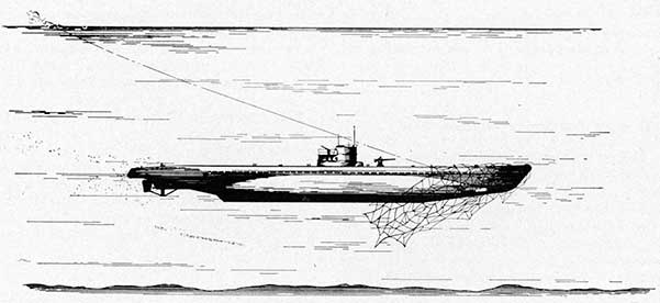
The appearance of a reliable, self-propelled automobile torpedo produced an immediate and insistent new demand for defense against both torpedoes themselves and against torpedo carrying craft. The first efforts were devoted to developing protection under way as well as at anchor and centered around various proposed designs for nets which, however, became so heavy and unwieldy that little progress was made.
As noted previously the Japanese torpedo attack upon the Russian fleet anchored just outside Port Arthur convinced the world that the torpedo was a really formidable weapon. The countermeasure favored in most navies, but not in the American service, was an arrangement of torpedo nets to be rigged from booms permanently fitted to major ships and swung out when a torpedo attack seemed imminent.
During the ten years following the Port Arthur attack torpedoes were rapidly gaining the ascendancy both through improvements in the speed, size and reliability of torpedoes and torpedo carrying craft and through improvements in net cutting devices to be fitted to the heads of torpedoes.
By 1913 torpedoes fitted with the latest types of cutters were penetrating every type of ship's torpedo net in service and the British, pioneers in this type of defense, did not install nets and their fittings on the Queen Elizabeth and later classes
of new ships. One of the difficulties, the British discovered, was that the torpedo net grommets then in use, were too small, 2 1/2 to 6 inches in diameter, to withstand the bursting power of a torpedo. Limitations of weight and the increased size of the furled net restricted improvements in that field.
Other difficulties were the impracticability of providing any effective yield to nets of this design and also the obvious risks of encumbering a fighting ship with a complicated arrangement of booms and heavy netting. Also a ship's speed would be radically reduced if the nets' were rigged out under way. As a result, by the time the World War began in 1914 most practical naval officers had realized that this countermeasure to torpedoes was not only far from dependable but also probably actually reduced a ship's over-all fighting efficiency.
Anti-Surface Craft Booms
Booms designed to stop torpedo carrying surface craft were in the process of development at the outbreak of the Russo-Japanese war. Several such booms, arranged as baffles in order to facilitate the passage of friendly craft, while making negotiation of the narrow, twisting channel difficult and dangerous to the enemy, were actually in place at Port Arthur the night of February 9th.
The narrowness of the entrance to Port Arthur prompted the Japanese to make three attempts to close it with block ships. The Russians countered by sinking blockships of their own which were in place in time to complicate the third and last Japanese attempt which, while it managed to drag the main Russian boom some distance out of position did not sink the Japanese blockships sufficiently close to the main ship channel to embarrass the Russians seriously, the defeat of the attempt probably being chargeable to the combined effect of the various defense measures taken. booms, counter-blockships, searchlights, mines and gunfire.
Destroyer Booms
Appearance of torpedo boats and their heavier successors, destroyers, prompted renewed efforts to devise booms capable of stopping these new and powerfully engined craft. Such booms, which
4
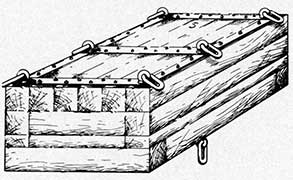
appeared early in the 20th century, were massive affairs and consisted of timber rafts held together by heavy wire jackstays. The ends were firmly and permanently secured forming a rigid barrier whose resistance to rupture depended entirely and directly upon the sheer strength of its materials.
In a test conducted in 1909 with an old British destroyer fitted with a knife edge cutter on her stem the boom was easily broken.
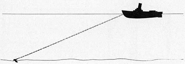
As a result of this test an entirely new type of boom was devised which brought a principle hitherto ignored in the field of booms and nets into play.
Using much lighter floats and connecting jackstays this boom relied for its efficiency upon the manner in which its ends were secured. These were led ashore. to rendering winches set to veer automatically but gradually under attack, the increasing steam pressure built up in the winch cylinders creating a progressively increasing resistance designed to reduce the speed of the attacking vessel gradually and thus deprive her of her chief resource, momentum, without developing breaking stresses in wires or their connections.
Actual tests carried out with this type of boom stopped a number of attacks and the yielding principle which is the basis of most successful net. and boom design, was definitely established. However, while this was the outstandingly successful service test of such barriers, careful consideration of all factors involved led the British to drop further attempts to develop a boom capable of stopping a full powered modern destroyer or large ship.
This decision probably represented the conclusion of most thoughtful naval officers of that time. For the destroyer used in that test displaced only 320 tons and was much smaller and less powerful than many newer types already in use. She never struck the boom at a higher speed than 21 knots. And it was apparent that with propeller guards and a specially fitted stem this or a larger destroyer easily might ride over such a boom.
In narrow, tortuous channels where it would be impossible to build up much speed a strong boom fitted with rendering winches or some other form of elastic yield might stop a destroyer. Based on this reasoning so-called "destroyer booms" were maintained for a time in some such locations. But most naval opinion concluded that this field of development was not promising.
World War Period
Seen in retrospect a salient feature of the 1914 naval situation was the then unrealized effectiveness of the submarine.
This was established quickly. In both the British and German navies only relatively few enthusiastic submarine officers realized the fighting and cruising capacities of even the primitive submarines then in commission. Service opinion in general looked upon submarines as coastal defense craft of very short range and limited and very dubious 'fighting capacity. The young submarine services soon altered this opinion.
Deprived of targets because the German fleet was held safely in its home bases along the shallow German coast the British submarine force established and maintained a close scouting line in the German Bight which provided reliable information on German ship movements. Three outstanding events typify the manner in which German submarines forced an immediate and drastic improvement of British anti-submarine measures.
Early in September the U-18 torpedoed and sank the British light cruiser Pathfinder near the entrance to the Firth of Forth. After the war Ger. man records revealed that previously she had penetrated the Firth almost to the bridge and that if she had continued only a little farther she might have bagged a British battle cruiser as readily as she did the Pathfinder a few hours later.
Shortly afterward one of the oldest and smallest German submarines in commission, U-9, came upon three large British armored cruisers, Aboukir, Cressy and Hogue, and bagged all three in quick succession.
Then, early in the morning of January 1st, 1915, U-21 torpedoed and sank the British battleship Formidable west of Portland.
The first two of these events spotlighted an unpleasant but urgent fact. No base or fleet anchorage on the east coast of the British Isles would be secure from attack by submarines until it could be protected by some effective barrier. The third by revealing how readily submarines could pass through the English Channel and attack the vital western approaches, forced an immediate attempt to close the Dover Straits to submarines.
None of the belligerents was prepared to meet the new menace of the submarine.. This was especially
5
true in the field of ordnance, nets, booms, mines, etc. War tests soon exposed vital flaws in design and even where design was reasonably adequate the supply available was woefully inadequate. The war had only continued a few days before the British suspected and the Germans knew that the standard British mine was not reliable. The German mine was little if any better until it was improved after studying some of the surprisingly efficient Russian mines the Germans secured intact in the Baltic. But that had no immediate bearing on the British problem of making the North Sea bases secure.
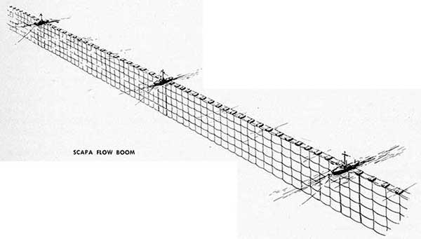
The only immediate action open to the British was to withdraw the Grand Fleet from its bases to the west coast of Scotland and the Irish bases until Scapa Flow and the other North Sea ports could be fitted with nets.
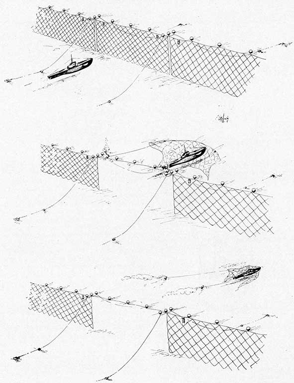
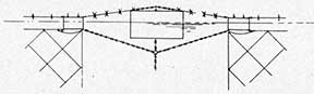
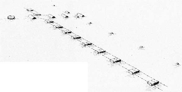
The type at hand was the anti-submarine net designed shortly before the outbreak of the war for Cromarty Firth. It consisted of a number of timber floats, connected by two jackstays. From the lower of these was suspended a net of 5/8" flexible steel wire rope made up in 12 foot square mesh. The net was laid in 600-foot sections, later reduced to 400 feet. A small vessel such as a trawler was moored at the end of each section with wire hawsers bent to rendering winches. One section was rigged to be swung around as a gate.
Although this design had not been given any service test it was placed in production immediately, the net line closing Cromarty Firth being completed by the end of October, 1914 and that closing the main entrance to Scapa Flow being finished early in 1915. The system of anti-submarine net defenses was extended to the principal ports of Great Britain and her allies as rapidly as material could be manufactured and assembled.
This immediate urgency of providing the most effective design of the anti-submarine net then available transformed it at once into the standard British design without the usual careful consideration and the service tests by which the reliability of any naval device is established. The continuous maintenance of the nets in all seasons and weathers and in many ports furnished a broad foundation of practical experience for improving nets when the end of the war freed the Allied Navies from relying entirely upon the only design for which materials had been provided in the vast quantities required.
Actually the nets originally installed delivered the security they were designed to give. As a scrutiny of German records after the war revealed, the enemy made no attempt to penetrate the nets defending naval bases until the very end of the war. No British ship defended by submarine nets was hit during the war, according to British records.
Probably this German failure to attack the nets was the result, in part, of the increasing concentration of German submarines against merchant shipping
6
at sea where it was at best only weakly protected. But, possibly as a result of their experiences with nets in the open sea at such places as Dover Strait, there is evidence that the German submarines had a healthy fear of attacking nets closing bases where they were bound to be much more formidable than in exposed situations in the open sea.
The one attack made upon a submarine net by the Germans strongly suggests that the security the Cromarty type net provided was largely an illusion.
On October 28, 1918 the U. B. 116 attacked Scapa Flow. The British report that she was first detected by hydrophones and then was picked up by searchlights. She dived and passed directly through the nets without her passing being observed, although subsequently she was sunk in a controlled mine field.
It is questionable whether the failure of the nets can be attributed justly to faulty design. For the particular nets in question had been in place for over 18 months and almost certainly had been seriously weakened by corrosion. But at any rate in this one war test of that type of net it offered so little resistance to the U. B. 116, which was equipped with net cutters, that the point where the submarine penetrated was only located by inspecting the net later. The rendering winches did not even start.
Open Sea Barriers
For several reasons the matter of protecting Allied shipping in the Dover Strait area was critically important. The bridge of ships across the Channel was the life line of support for the Allied army in France. The establishment of German submarine bases at Zeebrugge and Ostend provided secure bases within very short range of the Allied lifeline. Finally the sinking of the Formidable disclosed submarines, which won added days of hunting by passing through the Channel, now beginning to strike at the almost entirely undefended western approaches to Britain. When the Formidable went down demand for action was immediate and urgent.
The idea of employing nets for closing the Dover Straits had existed prior to the war, a British author wrote, "and during the autumn of 1914 experiments were carried out by several officers, yet
there was very little practical information available."
The day following the loss of the Formidable four drifters were secured at Lowestoft and fitted to operate nets to which they would ride much as they did with their herring nets.
This idea, which was simple and easily applied, was credited to Admiral Sir A. K. Wilson. The drifters could be used against submarines as they were, without any material alterations. Equipped with the nets and with explosive charges to be dropped on submarines entangled in their nets they were stationed in waters frequented by the underwater craft, particularly close to lighted buoys moored for their guidance close to the French Coast.
As the number of drifters on station increased encounters with submarines began to occur and apparently they did account for some of them. As an example a British account reports that on March 4, 1915 the drifter Robur reported a submarine afoul of her nets. The destroyers Cossack and Ghurka searched and the latter was officially credited with destroying the submarine U-8.
Meanwhile strenuous efforts were made to create an actual physical barrier of nets across the Channel at Dover Strait. This was to consist of heavy baulks, a large number of which were ordered, to be connected by heavy jackstays and support antisubmarine nets.
The strong currents and severe weather prevalent in the Channel blocked every effort to design and install such a barrier. Nets 120 feet deep were required over much of the length of the proposed barrier. Moorings capable of holding such a weight of net could not be produced. Admiral Sir Reginald Bacon, commanding the Dover Patrol, wrote later in discussing the project, "In the case of a barrage the use of pendants of chain of a length of four or six times the depth of water-is out of the question. The spring-like action of a long length of chain is, therefore, greatly reduced. Rings 2 1/2 inches and over were cut clean through after a few weeks service. Finally I was forced to report to the Admiralty that the whole scheme was impracticable."
He added that it was "evident that if any moored obstruction was to last in such a tideway, it would have to be of the lightest possible construction."
In addition to the attempt to establish a cross
7
Channel net line various bays and sheltered places where submarines might rest on the bottom were netted.
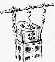
During the summer of 1915 electro-contact mines were developed and fitted to the nets, one at each end of each section. The nets were held lightly in a frame of flexible wire rope by steel clips, the mine batteries being held in separate water tight holders attached to buoys. When the submarine struck the net the clips broke and the net was carried on until a mine struck the submarine and fired.
Results achieved with this mined net were at best inconclusive. Much trouble was experienced with the mine batteries which frequently failed. The British also had doubts about the effectiveness of the parting clips. When the submarine came down current the additional pull parted the clips without difficulty. But when the submarine attacked up current there were indications that it sometimes cut through the net without parting the clips.
Increasingly, as experience with submarines accumulated, British opinion favored a deep, wide mine field as the most effective means of closing the Channel. Accordingly, mines were laid parallel to the barrage line and developed both in depth and length until the mine field became the most formidable and possibly the only effective feature of the Dover Barrage.
Undoubtedly the combined net-mine barrier was an embarrassment to submarines but it fell far short of what its advocates hoped for it. And they expected a great deal. One of them, writing after the war still retained sufficient faith in the project to say:
The famous Dover barrage was a combination of mines and nets and it proved almost completely effective. So that the Flanders coast U-boat flotillas from Ostend and Zeebrugge could only reach the Channel through the northern passage. The barrage was watched by numbers of trawlers and drifters which, at night, lit up the straits from shore to shore with flares and searchlights so that no submarine could hope to creep through on the surface.
In sharp contrast with this glowing tribute Ernst Hashagen, one of the most able submarine commanders, commented in his "Log of a U-boat Commander" regarding a successful passage through the barrier in August 1917:
The depth of water between Dover and Calais varied from 12 to 20 fathoms. Only in one place did it obtain,
for a width of about a thousand yards, a depth of 26 fathoms. This part was called the deep water channel. Here it was that the biggest possibility offered of getting smoothly through the barrage, if the worst came to the worst and we were compelled to force our passage under water. We assumed that the nets would not hang right down to the sea bottom at this point. The nets were hung from big buoys and innumerable little floats, visible on the surface by day.
The war logs of German submarines, many of which came to light after the end of the war, amply supported this testimony. Even with the strong drifter-trawler-destroyer patrol maintained by the British, submarines crossed the barrier on the surface almost with impunity and frequently when they did become entangled in the nets, freed themselves and continued on their way. U-32, for example, reported that she became fouled in the Dover nets. She lay on the bottom until night. After dark she surfaced and freed herself and proceeded on her way.
Chatterton, in his history of the Channel war, summarized the conservative British view as follows:
. . . but the truth may at once be admitted: this net idea was not a reliable barrier. Indeed, not till the last year of hostilities and efficient mine fields were .laid, was the Dover defile any more difficult to a U-boat than a wooden gate to an active pedestrian.
Admiral Bacon, the responsible officer in command, shared this view.
There is no doubt [he wrote] that the barrage never stopped submarines passing.
Occasionally information was received that they had fouled the nets and in one case a boat was badly damaged by a mine but just crept home.
There also was local evidence of the loss of two or perhaps three submarines but they still passed. The danger was too remote in the absence of mines to guard the lower depths. Also in a strong tide it was a simple matter for submarines to pass on the surface.
"The only thing possible," Admiral Bacon concluded, "was a good mine field." And when really good mines were developed the Channel was closed to submarines. Hashagen, in reviewing German experience with the Channel Barrage wrote:
This they succeeded in doing in the middle of 1918, at last, after nearly four years of effort. We gave them time enough. When, of six boats stationed in Flanders which sailed together from Zeebrugge only one returned, we had to abandon the Flanders Submarine Base.
8
Sealing the Flanders Bases
British attempts to destroy, seal or neutralize the submarine bases the Germans established on the coast of Flanders furnished another large scale laboratory test of anti-submarine equipment and methods for open sea areas in shallow or narrow waters.
By the spring of 1915 activities of German submarines based on Zeebrugge and Ostend were seriously embarrassing the British. The U-boats used both mines planted from submarines and torpedoes. Drift nets off the submarine bases were the first device tried and while at least one submarine was destroyed by them, as soon as the submarines learned to steer clear of the drifters the latter had little effect.
Early in 1916 the Belgian Coast Barrage was laid. It consisted of a double line of mines backed up by a line of mined nets with a line of indicator nets rigged from drifters anchored to seaward of the mined net line. Admiral Bacon believed that this barrage prevented all enemy mine laying in the Dover area for over five months. But there are indications that this view was somewhat prejudiced. Commander Schultz, of the German Flanders Submarine Flotillas, commented later that as the barrage was patrolled only at night it was simple for the Germans to remove enough of the nets to let their submarines through. While the barrage probably was not fully effective, as another British commentator remarked: "It certainly was to the enemy a nuisance and a hindrance."
The barrage was laid in April, 1916 by four fast vessels. It consisted of 15 miles of double line mines and 13 1/2, miles of moored mined nets "of which 11 miles had been made active" Admiral Bacon reported. In addition 18 miles of drift nets backed up the barrage.
In the process of laying the barrage the British concluded that several submarines were destroyed, four and possibly five being claimed. But in the absence of confirmation such as locating the sunken submarines by divers or official German admissions of the losses during or after the war these claims cannot be accepted as conclusive.
As time passed it became evident that drift nets were out of date. The enemy submarines knew all about them and merely steered clear of them.
The protection provided for the blocking expedition against Zeebrugge and Ostend later furnished another test of net material. The British created "a zareba of nets maintained by eighty drifters consisting of nine miles of mined nets and seven miles of ordinary nets-and the tide a clock tide."
"The drift nets and the destroyer patrols which flanked all three sides of the zareba, steaming at 16 knots, forming the anti-submarine defense."
Sealing the Northern Approaches
A third feature of the general anti-submarine campaign, the attempt to close the Scotland-Norway entrance to the North Sea, did not involve nets. It is noteworthy because of the wide' variance between the Allied and the German view of its effectiveness. While it undoubtedly was a formidable barrier German comment indicates that in any consideration of means of closing wide stretches of sea against submarines a very large mine field such as this should not be accepted as a completely effective barrier. Hashagen, who seems to have been a dependable authority, reports that: "according to our records two or three at the outside" submarines were destroyed in the North Sea Minefield. "At all events," he continued, "it appears that the efficiency of the barrage was improved about midsummer of 1918. I myself went through the middle of it three times in broad daylight, in the summer of 1918. That always appeared safer to us, than to force our way through close under the coast of Norway or Scotland."
Sealing the Adriatic
Attempts to close the Adriatic to submarines operating from Austrian bases paralleled the Channel Barrage effort although because of the greater depth of water it was not practicable to use minefields effectively. Drifters using indicator and mined nets may have accounted for a submarine or two but in general with the equipment then available probably there never was a time when a submarine could not attack the barrier with the chances strongly in its favor either by diving well under the nets or by crossing on the surface under cover of darkness or bad weather.
9
The Dardanelles
In this area both British and German submarines brought out data on the performance and reliability of submarine nets in service.
The former repeatedly penetrated the heavy submarine nets maintained by the Turks across the narrow strait. These experiences furnish concrete evidence on both the performance to be expected of nets and upon their limitations.
E-2, for example, reported that off Nagara she ran into a submarine net. Through the conning tower eye ports a large wire cable was seen caught _under the barrel of the gun. Another smaller cable was caught against the conning tower and still another was fouled around the wireless mast aft. The E-2 maneuvered for ten minutes to get clear "during which time patrol boats threw down many bombs."
In another instance E-12 ran into the Nagara net, broke off part of it and towed it with her. The extra weight carried the boat down, especially as one strand had jammed the forward hydroplanes. She went down to 245 feet. The conning tower eyeports crashed in and the conning tower was closed off. Leaks developed in the forward compartment. After ten minutes the hydroplanes cleared and she shot to the surface. She ran into another net a little later at Kalid Bahr and in clearing herself from that she also shook off the remains of the Nagara net.
These experiences demonstrated how readily, in the absence of an alert, well-equipped net patrol, a submarine may break through even a heavy submarine net. Not long afterward E-7 figured in an encounter which proved what nets can do.
At 0730 she sighted the Nagara net buoys and dove to 100 feet, increasing speed to 7 1/2 knots. When she struck the net it fouled her starboard propeller and she went broadside into the net. A mine exploded but without doing any damage to the boat. For two hours she tried vainly to get clear then stopped her efforts in order to wait for darkness. But the patrol had located her and began to drop explosive charges. At 1840 when she had suffered severe damage from the explosive charges she surfaced and surrendered.
German submarines, attacking the British fleet off the entrance to the Dardanelles, sank the battleships Triumph and Majestic, with torpedoes which
passed through the old-type torpedo nets with which those ships were equipped.
Baltic Naval Campaign
The Baltic operations between the German and Russian naval forces, the latter for a time in the latter part of the war including a detachment of British submarines, did not produce any conclusive test of nets, although conditions favorable for nets, relative narrow, shallow waters and short distances separating hostile bases, did exist.
The Russians, who possessed perhaps the most efficient mines in use at the opening of the war, relied almost entirely upon minefields for protection and their own submarines played relatively little part in the campaign. German submarines had their hands full elsewhere and used the Baltic chiefly for training cruises. The Russian mines did score a number of successes, in one destroyer raid into the Gulf of Finland by 11 destroyers, the Germans losing, according to Captain A. Gayer, of the Germany navy, 6 destroyers to mines.
Motorboat Booms
Booms as a defense against fast, shallow draft coastal motor torpedo boats appeared. to meet the threat of these boats in the Channel and Adriatic areas. Developing a speed of approximately 45 knots with a draught as shallow as two feet motorboats were a real menace where opposing bases were close to each other.
Three types of defense were tried. The first consisted of logs fitted with spikes and strung together in a boom. But after a brief trial near Dunkirk the design was abandoned, the logs tending to roll and tangle the boom even in comparatively mild summer weather.
The second experiment featured what was called the "Table Cloth Defense" and consisted of a light net made up with square meshes and floated on the surface with small steel floats. It was designed to be practically invisible and to foul the propellers of motorboats attempting to run over it but it also failed in service as the nets bunched in bad weather and on changes of the tide.
The third type, which was developed shortly before the close of the war, proved to be the forerunner
10
of modern motorboat booms. It used heavy baulks of the Dover type and was fitted with spike cutters on baulks and connecting jackstays.
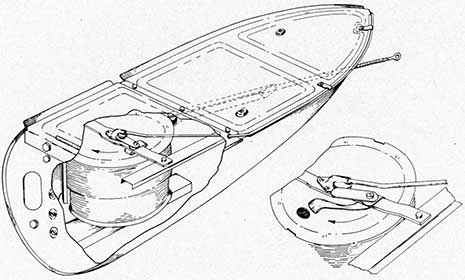
Lighter Submarine Nets
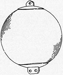
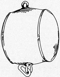
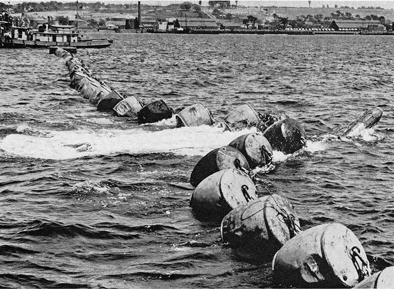
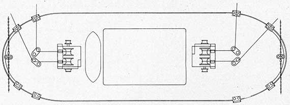
The demand for a lighter type of submarine net than the heavy and bulky standard net produced in 1915 a light net woven of 5/8-inch flexible steel wire with 12-foot square meshes, floated by steel barrel buoys with 1,000-pound weights attached to the foot at intervals and moored to anchors at the ends. It was laid from ships underway, three paddle steamers, the "Mona's Isle", "Prince Edward" and "Queen Victoria", being converted from this service by removing fittings from the after decks and substituting troughs on either side to take the nets, weights and floats, the mooring anchors being hung over the stern. The dimensions of the ships were:-Length: 330 feet; beam, 30 feet; draught, 15 feet. They were capable of making 11 knots, the usual laying speed being 7 knots.
It is reported that the Mona's Isle loaded one mile of this net, approximately 96 tons, in six hours and laid the defense the same day.
As the standard submarine net obviously was too heavy and bulky for use at advanced bases and remote ports this lighter type of net was extensively installed in the Mediterranean and elsewhere. At the more important bases it was sometimes replaced with the standard installation when materials could be shipped. The type never was subjected to attack and in the light of post-war experience it is unlikely that it would have stopped even the smaller types of submarines.
While it probably still is impossible to lay a net capable of stopping submarines from ships in the rapid manner described, experience gained with this type of net formed the starting point for work on modern types of indicator nets to be used from and at advanced bases.
Summary of War Experience
As a primarily defensive device nets registered few positive successes in the World War. The most reliable estimate on submarine losses of the German navy record that 178 submarines were lost by enemy action. Of these six were credited to "net barrages". And this figure probably included
submarines lost in mined nets and drifter nets which usually only indicated the location of the submerged submarine and enabled attendant surface craft to destroy her.
One British submarine, the E-7, was trapped in the Dardanelles net as has been recorded previously.
On the other hand nets were the primary defense installed at the British main bases and whether or not they were as efficient as was believed at the time, their mere existence prevented attack by submarines. And no British ship so protected was lost during the war.
Regarding mined nets the results of this, the most extensive service test of nets until the outbreak of the second World War, were inconclusive. Weaknesses of the type were exposed, such as the difficulty of maintaining electric firing batteries and the dangers of handling and the hazard to friendly vessels. Meanwhile, the appearance of depth charges in large quantities and the development of really efficient listening gear helped deflect attention from mined nets.
However, mined nets did account for submarines and did provide an anti-submarine device which, if properly installed and maintained, was complete in itself and able to destroy a submarine without aid from surface craft.
British experience also indicated the difficulty and danger of using minefields in close proximity to net lines. The Dover Barrage demonstrated that at least with heavy nets long net lines could not be successfully maintained in the open sea where currents were strong and weather severe.
The special problem of protecting the numerous major bases of the British Isles at relatively short distances from enemy submarine bases was met by establishing elaborate systems of heavy submarine nets. But the war also indicated that these nets and their fittings were much too heavy and bulky for use on a worldwide scale. This emphasized the need for developing lighter nets sufficiently strong for temporary use at distant points.
Post-War
At the close of the war virtually no data on the performance of nets under attack existed. The few attacks that were made, such as British ventures into the Dardanelles and the U. B. 116's penetration
11
into Scapa Flow indicated that a determined attack against nets at any major naval base probably would have succeeded. The endeavor to analyze and extend practical war experience with nets and booms began with recognition that untested barriers almost always have failed under actual attack.
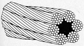
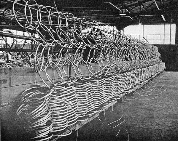
The existence of large quantities of the Dover Strait baulks furnished a starting point for establishing a standard type of anti-submarine net. War experience indicated that the Cromarty type net, woven of flexible steel wire and suspended from a double 1 5/8 inch jackstay floated by the baulks had the best endurance qualities.
As used during the war these nets were rigged in 600-foot sections the ends of which were led to rendering winches on trawlers or other vessels moored as parts of the net line.
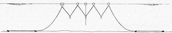
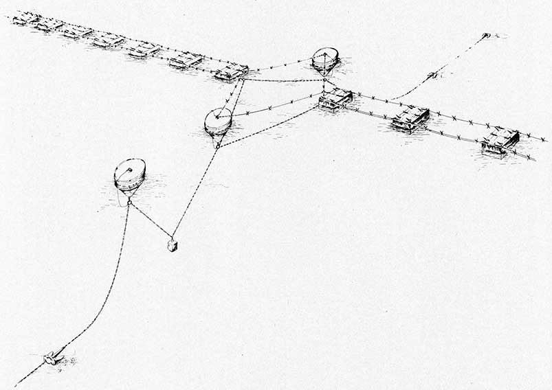
The idea of making the yielding arrangement part of the net itself developed in 1922 and this improvement, embodied in a net laid at Spithead in 1923, marked the greatest single advance in net design, vastly strengthening its resistance both to submarine attack and to current.
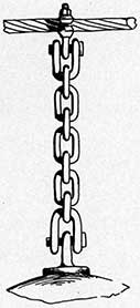
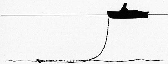
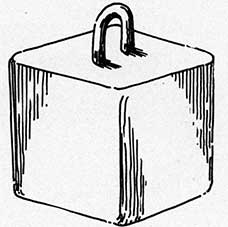
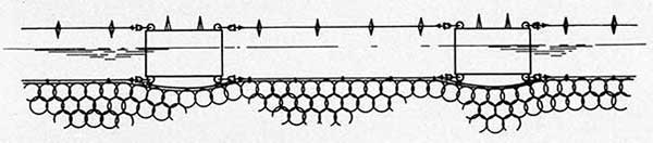
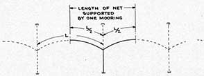
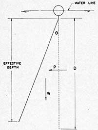
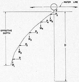
The performance of the self-yielding net is described in detail in Chapter IV following. In brief it applies the oldest principle of ground tackle to net design by insuring that any stress will be taken up gradually and distributed throughout the entire system. This is achieved by suspending heavy weights to the chains connecting the series of large buoys forming each section mooring. The net is permitted to travel forward under attack to the limit permitted by the length of chain connecting buoys and weights. Mechanically the system's resistance, relatively slight at first, is progressively increased to its maximum capacity very much as arrestor gear is used on carriers to reduce a landing plane's very high initial velocity to zero in the shortest possible distance.
Resistance to Cutters
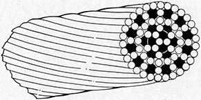
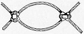
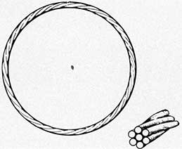
Investigation suggested that a single strand mesh rope made up of a small number of large gauge wires would better resist submarines' net cutters than the usual six-strand wire rope. Mesh ropes of this type were produced and tests proved this idea to be correct.
1925 Full-Scale Trials
In order to test the actual strength of submarine nets the submarine L-11 was assigned to attack the net laid at Spithead.
In the first run, made on the surface for reasons of safety, the submarine was stopped.
She then made a submerged attack without net cutters and was successfully stopped.
Next L-17, specially fitted with knife and serrated cutters at the bow, attacked the net and penetrated. This established the effectiveness of the cutters against the net as then rigged. But study of the test suggested that the net's initial resistance was so high that it was cut before the yielding system could be brought fully into play.
Light steel barrel floats were then substituted for the cumbersome timber baulks and two months later two more runs against the altered net were made by L-17, fitted with bow cutters. L-17 was stopped on both occasions. The submarine net as thus modified was then adopted as the standard submarine net.
The immediate improvement in net performance under attack achieved by substituting light flotation for the bulky, heavy timber baulks suggests one reason, although certainly not the only reason, for the failure of the Dover Strait installation. Under the severe conditions often obtaining in that area the very high resistance the baulks exerted to current must have greatly increased the strain upon all net fittings.
Self-Yielding Gate
Development of the elastic yield net was next applied to the gate section required wherever traffic must pass through the net line. As installed gates were operated by two gate vessels moored in the net line. These opened the gate when required and closed it after friendly ships had passed through. When closed the gate section was required to be just as strong under attack as other parts of the net.
The problem was solved by providing that, when attacked, the gate section would automatically detach itself from the gate vessels and then yield with the rest of the net. Each gate vessel was rigged to permit the net jackstay to pass over a turtle shaped deck on the up-harbor side, from which it could be released under attack.
12
Attack trials of this type of gate made in conjunction with 1925 tests were satisfactory.
Explosive Cutters
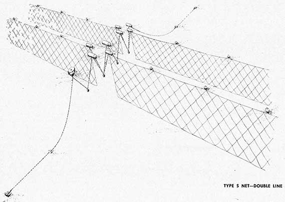
In August 1926 the L-17, fitted. with a series of explosive wire cutters ("T" type) bolted at intervals along the cutter bars, attacked,a submarine net off Kinghorn Ness, at her maximum submerged speed of 9 knots. In the first attack the net was penetrated. In a second the submarine was held. It was clear that addition of the "T" type cutter improved the submarine's chance of penetrating the net. Also that net design should be improved and that until this could be done a double line of submarine net could be used in an emergency with considerable chance of stopping cutter-equipped submarines.
Chain Nets
In 1926 a net constructed of 3/4-inch chain, 12-foot mesh, was tried and failed. The chains snapped easily when attacked, before the inertia of the floats could be overcome. Although the use of old chain may have contributed to the failure the result was not sufficiently promising to encourage further experiment.
Net for Rapid Laying
One of the nets designed during the war for rapid laying at advanced bases and not equipped with elastic yield was tested in 1927. It was penetrated four times by an L class submarine armed with knife cutters and moving at speeds of 4 1/2 to 9 knots.
Double Line, One-Inch Mesh
In 1929 a net designed to defeat explosive cutters was tested. It was woven of one-inch flexible steel wire and was further strengthened by reducing the size of the mesh to 8 feet. Diagonal and square mesh nets were both tested on the theory that diagonal mesh might have more chance of fouling the cutters. The trials did not confirm this last supposition but the diagonal mesh was preferred, being cheaper and more simple to construct.
The submarine Oberon, with a submerged displacement of 2,000 tons, was used for the tests. She was specially fitted with an improved system of knife cutters; in addition to bow and hydroplane guard cutters, the top bar extended from the bow to the periscope housing; and 16 explosive "T" cutters were fitted to the frame work.
The net was installed in double line. Four attacks were made. In the first two the explosive cutters were found to be defective. This was corrected for the last two runs. The submarine was stopped on each occasion. However it was suggested that a higher speed would have increased the submarine's chance of penetrating the barrier, (the maximum speed recorded was 7.6 knots) and that the net cutters could be improved.
Single Line One-Inch Mesh Rope Net
Runs also were made at this time against a single line installation of the one-inch mesh rope net by the Oberon armed with knife cutters and the submarine was stopped.
Heavier Wire and Larger Mesh
A special net woven with mesh rope 1/3 heavier than the one-inch with 18-foot meshes to compensate for the greater weight was also tested but did not show any definite superiority over the one-inch mesh rope-8-foot mesh net.
Test with Improved Net Cutters
In 1931 one of the latest submarines, H. M. S. Regulus, with a submerged speed of 9 knots was fitted with improved net cutters consisting of tool steel knife edges at the bow around the hydroplane guards and under the keel forward and also a rigid bar extending from right forward to the top of the periscope housing. Thirty-two explosive "T" cutters were fitted in pairs along the various bars.
Two runs were made by the Regulus, fully armed and at maximum speed against the double line of one-inch rope unit nets. The submarine was brought up on each occasion and held between the two lines of net, thus establishing the effectiveness of the double line installation against a modern submarine equipped with all known types of cutters.
13
As a result of this series of tests the one-inch rope unit net with 8-foot mesh was adopted as the standard British heavy submarine net, double line installations being preferred for protecting all major bases.
"Trulay" Wire Nets
A special net consisting of one-inch "Trulay" wire ropes had been prepared for trial as a substitute for standard rope unit wire, the "Trulay" wire being preformed to obviate the tendency of strands to open out when cut. As, however, most of the cutting of nets evidently is done by the explosive cutters this is a doubtful advantage and the "Trulay" wire did not resist cutting as well as the rope unit. Two runs were made by the Regulus and in both the nets failed.
Detection of Attack
Signal apparatus designed to reveal the particular section of net being attacked was tested during these trials and functioned effectively, demonstrating the practicability of using smoke-flare indicator signals with submarine nets where considered necessary. Later American experience demonstrated that such indicators on submarine nets are too easily tripped by current to be considered reliable.
Torpedo Net Tests
The only major improvement effected in torpedo net design during the 1918-1939 period was the development of lighter types of floats to replace the cumbersome timber baulks left over from the Dover Strait experiment. This, however, was a material advance and pointed to the other improvements destined to be made when war again stimulated the demand for a lighter and more easily handled type of anti-torpedo defense.
During this period, however, tests were made in an effort to develop a lighter form of torpedo net.
Inclination of Net to Attack
A test was made to determine whether a type T net would have increased efficiency if laid at an
angle of 60 degrees to the probable course of the torpedo. It was found that it did not. The net is more likely to stop a torpedo when the cutter, if fitted, enters a grommet without engaging it, which becomes less probable as the angle of impact is decreased.
Spiral Net
A net consisting of a series of vertically hung interlocking spirals designed to give more yield than grommets was tested. Only one torpedo in five was stopped.
Double Nets
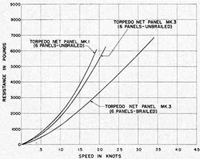
Trials with double line type T nets were carried out in 1922. The double line net was found to be from 90 to 95 per cent efficient against 21-inch torpedoes armed with E.2 pioneers (cutters) and set to run at 45 knots. And the distance apart for double torpedo net lines was decided upon as 45 feet. A single line was found to be 60 per cent efficient against torpedoes fitted with cutters. To reduce the chances of fouling and minimize damage to second line by a torpedo exploding in the first line of net, in the American practice this distance is increased to 100 feet.
Spiral Nets
Another type of interlocked spiral net was tried in 1923 and 1925 as a first line net intended to choke or fire the explosive cutter before it reached the second line. This, however, it failed to do.
Special Grommets
Additional tests were carried out using torpedo nets of the "U" and "V" types, the front line, "V" type being made of 17-inch grommets of 3-gauge wire (a size larger than the standard T net grommet) and the second line, "U" type of 18-inch grommet of 3-gauge wire. The "V" net was four times and the "U" net six times interwoven. That is, each grommet was interlocked, in the first case with four and the second six other grommets.
The defense was not penetrated but the combination was not recommended because the "U" net
14
proved to be heavier and more difficult to handle than the T type.
In the above test, however, the "V" type net seemed to have possibilities because, although using larger gauge wire (No. 3) than the "T" net (No. 4) it was no heavier, as it was only four times interwoven instead of six; that is, fewer grommets went to make up a net of a given size.
The next tests, therefore, were made with various combinations of "V" net using lighter wire and the standard T net. These trials revealed the important fact that with four times interwoven grommets torpedoes could penetrate between the grommets by distortion and without actually cutting any grommet. This type of construction therefore was abandoned.
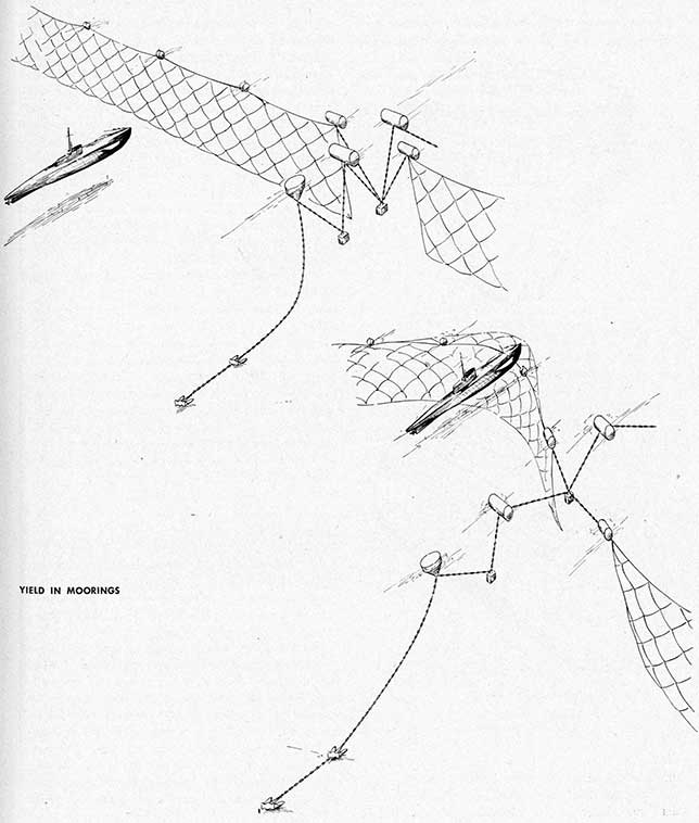
Yielding Moorings
The problem of imparting some form of resiliency to the net was again considered and to test out the principle of resilient moorings a number of torpedoes were fired at a line of net which was slipped from its moorings so that it was floating freely when struck. The results indicated an efficiency of 70% under these extreme conditions as compared with 60% for a moored net. The conclusions drawn from these trials were:-
(a) that resiliency in the mooring system will not prevent penetrations;
(b) that local resiliency in the net, if of a high order, will improve their efficiency;
(c) that even if this local resiliency can be furnished, double lines would still be necessary to obtain high efficiency against cutters.
It was thus apparent that the standard Type T net then available was the best that could be provided with the existing materials and knowledge.
Motor Torpedo boat Booms
At the end of the World War the only promising defense against motor torpedo boats was that of the superimposed jackstay type. Two surface jackstays were fitted to brackets on timber floats, about 1 foot and 3 feet, respectively above the water, the lower being between 6 and 7 feet to seaward of the upper. It was proposed to fit steel spikes to the jackstays.
This type of boom was laid at Stokes Bay, in 1922 and was attacked by a 40-foot C. M. B. The boat was not manned but was under directional control from an airplane. The result was inconclusive because spikes were not fitted. The boat passed over the boom but was damaged and it was not clear whether spikes, if fitted, would have caused sufficient damage to have stopped the boat.
Additional Tests
The 1922 trials led to the conclusion that, if the jackstays were not fitted with spikes, the barrier must be high enough to prevent the C. M. B., specially trimmed and at high speed, from riding over it. If, however, the defense was to stand the shock of impact, either it would have to be very massive or be capable of yielding adequately.
Accordingly a design was produced in which each float was fitted with a mast to a height of 8 feet above the water level, and a net of approximately 3/4-inch diameter rope unit wire was hung between the tops of each pair of masts by 2-ton parting clips. The net was attached at each end by a length of wire led to a small winch with a friction brake, situated on each float.
This barrier was attacked by a 55-foot C. M. B. at between 30 and 35 knots, steered by a volunteer helmsman. The net was carried away from the masts, wrapping around the bow of the boat and the winches paid out until the boat was brought to rest.
The Destructive Type
After the C. M. B. had been repaired a run was made on a boom of the destructive type, steel spikes being fitted to jackstays and baulks. The attack was made at the same speed as before, the helmsman reporting that considerable concussion was felt. The C. M. B. pulled up with a jerk, then went on and cleared the boom. In doing so, however, the steering gear and the shaft of one engine were put out of action, and the attack was ended by the rapid filling of the boat through holes torn in her hull.
As a result of these tests it was decided to standardize upon a motorboat boom of the destructive type, as being more effective and easier to rig than one of the yielding net rig.
15
Indicator Nets
The story of the part played by indicator nets against submarines in the Channel-North Sea and Adriatic areas is not entirely clear, being confused somewhat by the widespread use of drifters, beginning directly after the sinking of the Formidable disclosed the menace of submarines using the short route through the Channel to attack Allied shipping in the vital Lands End area.
Apparently several types of nets were used with drifters. Where the drifter nets were incapable of holding a submarine in place, which they could not do, they were, in effect, indicator nets with the drifter operating the net functioning as an indicator of the submarine's position. Yet such an arrangement was not technically an indicator net. The introduction of mined nets further confused this picture.
The British official account states that indicator nets were extensively used without attaining any positive successes. It reports:
Apart from the defense of major harbors, achieved by means of anti-submarine booms designed to prevent the passage of a submarine, indicator nets were introduced in large quantities from February, 1915, onwards. The function of these nets is, as their name implies, to advertise the presence of, a submarine but not to stop her.
Indicator nets were, in general, laid over large areas in the open sea for extended periods.
Later, in commenting upon post-war experiments, this account reports that until the 1926 trials of various types of nets indicator nets had never been subjected to conclusive efficiency trials, "there being no record of an enemy submarine being destroyed as a result of encountering such nets."
Comparison Of official British comment with ancillary discussion of anti-submarine measures during the war in the numerous books published after the war concerning Channel and North Sea activities suggests that war experience with nets of the indicator type developed somewhat more promise than the official comment would indicate.
It is clear from all accounts that indicator nets were extensively used. This was to be expected, as the indicator net is the only type which is adapted to use in quantity in open sea areas.
Some of the unofficial accounts seem worth noting in any consideration of the use of indicator nets. For example, it seems to be established that U-8, previously mentioned in this chapter, fell victim
to a successful use of the indicator net principle if not actually to indicator net. At 12:30 on March 4, 1915 the drifter Robur reported a submarine afoul of her net. The submarine was sunk by one of the two destroyers answering the drifter's signal for help, was identified as the U-8 and the drifters engaged (apparently a second drifter figured in the incident) were paid a reward of 500 pounds by the Admiralty.
The mined nets which did depart from the indicator principle did not appear until somewhat later. The nets did not destroy the U-8 but according to this account, which has not been contradicted, the nets definitely indicated the submarine's position to the ships which did destroy her.
C. W. Domville-Fife, writing in "Submarine Warfare Today", 1919, reported that indicator nets suspended from glass floats were used with "considerable success" until the enemy learned to watch for them. One of the disadvantages, he reported, was the "impossibility" of laying or retrieving them in rough seas. Another was the difficulty of laying them without being seen by the enemy.
Reports of anti-submarine measures during the early part of the war also record instances where drifters entangled submarines in their nets and claimed the sinking of the submarines with improvised explosive charges.
Most such reports are not sufficiently conclusive to be accepted as reliable facts, but the evidence does indicate that war experience amply justified the extensive British investigation of indicator nets initiated after the Armistice.
This investigation immediately uncovered a strong additional reason for reexamining indicator nets in disclosing that wartime designs were faulty and the nets could not be relied upon to function properly under attack.
The successful application of the yield principle to submarine nets in 1923 strengthened the suspicion, developed by naval officers during the war, that under certain conditions submarines might penetrate indicator nets without tripping the parting clips, for no appreciable yield was provided in the wartime nets. To test this, nets on the original design were rigged, the official British report of the experiment continuing as follows:
The nets were made of 3/8 inch circumference flexible steel wire rope in 12 foot square mesh; the head of each section of net was secured by parting clips to a jackstay, the sides
16
similarly to the sinker pendants between sections, and the bottom in the same way to a footrope secured between the sinker pendants. The lengths of the net, jackstay and foot-rope were equal and the distance between the jackstay and footrope was equal to the depth of the net.
Apart from any slack in the sinker pendants which would only allow movement of the whole line of nets, the defense thus was almost devoid of resiliency.
Five attacks by submarines were made at various speeds and depths and, as would have been expected in the light of more recent knowledge, the defense was penetrated on three occasions when the nets remained secured to the framework by the parting clips.
The large mesh, while reducing the resistance of the net to movement through the water, facilitated penetration because of the small number of parts of wire which had to be cut or broken to allow the submarine to pass through.
The trials thus made it clear that the design needed complete revision.
Requirements for a heavy type of indicator net were drawn up based upon the results of these trials. They were set forth by the British as follows:
The object of this form of indicator net is to provide a form of A/S protection to a temporary anchorage or to a fleet anchorage prior to the establishment of the heavier defenses, such that the first-line defense may be in position within 24 hours of arrival and that it may remain efficient long enough for the A/S booms to be prepared, shipped and laid, should the temporary base become permanent.
The requirements for such a net may be summarized under the following heads:
(a) It must be efficient as a detector of submarine attack even if the vessel be armed against nets.
(b) It must be capable of being carried in a netlayer which can accompany the Fleet, and the ready-use sections capable of being laid within 24 hours of arrival. It must be capable of being recovered and relaid when required.
(c) It must be capable of withstanding the action of tide and sea such as are likely to be experienced at the entrance to a fleet anchorage, for a sufficient period to permit of other provision being made. It is assumed that such period might be as long as six months.
1929 Trials
Full-scale trials of the net developed to fill these specifications were conducted and demonstrated
the soundness of the design. It was thought, however, that a lighter design might meet the requirements equally well with great saving of weight of material and time required to lay.
1931 Trials
A modified design was developed as follows:
1 1/2 inch (circumference) mesh rope was substituted for the 2-inch rope unit wire used in the previous design. The mesh of the nets was altered from 8-foot. square to 8-foot diagonal because the diagonal mesh could be constructed more easily and cheaply and tests had demonstrated that diagonal and square mesh resisted penetration and cutting equally.
Both the heavy and the modified designs were secured by parting clips to a 2 1/2-inch (diameter) flexible steel wire jackstay. carrying the flotation and provided with suitable moorings.
To provide yield to defeat penetration on first contact the clips at bottom and sides and the foot-rope were omitted, the net being held in position only by clips at the head. Further the nets were no longer secured taut along the jackstay but were made slightly longer and the net was bunched to increase local yield.
Submarine and endurance trials proved this design and it was adopted as standard for rapid netlaying operations.
Lighter Indicator Nets
Subsequent investigation and trials resulted in additional types of very light indicator nets adapted to laying by fleet personnel using ships' boats and capable of standing up under average conditions and light current for purely temporary use.
17
18
This page is blank.
19
CHAPTER II
1939-1944 Research and War Development
On the opening of the war in 1939, as In 1914, marked improvements in the use of torpedoes, this time by aircraft as well as by submarines, seriously complicated the problem of providing security at the major fleet bases and exerted severe pressure upon designers and producers of nets.
The sinking of the British battleship Royal Oak on October 14, 1939, by a German submarine undoubtedly increased the pressure upon the British net establishment. The evidence indicated that the submarine either entered through a gap between the blockships closing one of the entrances to Scapa Flow or through a gate in the single net line when opened for the passage of British ships. But there is nothing in the record to indicate that the British 'submarine net failed in this case as far as soundness of design or effectiveness was concerned.
Rather the German success was a triumph for the German intelligence service which had located a fault in the Scapa Flow defenses and enabled the submarine to capitalize the weakness, possibly with the help of a "War Pilot," that is, a merchant officer with exact local knowledge, to pilot the submarine into the base.
In spite of this early success and its implication that standard submarine net defenses did not provide security against submarines a survey of the factors involved suggests that, on the contrary, four years of war established the effectiveness of such defenses, when properly used. Properly maintained and patrolled and combined with other types of defense, loops, etc., they provide as nearly complete protection against submarines as can be expected in war.
As the war developed the German submarine attack was directed almost exclusively against British supply lines rather than against her fleet bases. Even when full allowance is made for this the obvious advantages to be derived from scoring further
successes with submarines against, ships at their bases must have impelled the German naval staff to study fully the possibility of following up the Royal Oak sinking.
In time the Nazis abandoned their early effort to appease British opinion and launched an all out attack from nearby bases on the coasts of France and the Low Countries. It then became apparent that because of the menace of aircraft and submarines the British not only no longer controlled the North Sea but that under the new conditions. Grand Fleet units could not operate without excessive risks in any waters within striking distance of German air bases. In other words the British could not, as in the early days of the first World War, seek safety in the open sea.
The long, stubborn and very costly air bombing of London revealed how much the Nazis were willing to bid in an effort to break the spirit of the British people. Yet it is difficult to imagine anything that would have been a greater blow to British morale than successful attacks upon the Fleet, traditionally looked upon as Britain's first line of defense.
From the German point of view a few, three or four or a half dozen torpedoes exploded against major British ships at their home bases must have been a possibility long and carefully considered. The fact that it was not attempted on any serious scale indicates that notwithstanding the great value of success the chance of penetrating the defenses was considered too slight to warrant the attempt.
That silent tribute by the Germans with their. numerous nearby bases and their rapidly increasing-fleet of submarines is a striking evidence of their respect for nets and the other elements of base defense. Developments in the Mediterranean area extended this demonstration. There again large
20
fleet units were forced to use bases in close proximity to enemy submarine bases. Nevertheless in four years of intensive war no submarine has broken through a submarine net. The only successes scored trace directly to careless patrolling or lax operation of base defenses.
In view of the pressure for rapid improvement of other types of net defenses and the difficulties of transport which definitely restrict the use of heavy submarine nets to major bases these facts provide reasonable justification for recognizing the effectiveness of heavy submarine nets in order to concentrate research and development upon other and pressing needs brought out by war experience.
When the British attacked the Italian fleet at its Taranto base with torpedo and bombing planes, crushing damage was inflicted. That successful attack revealed the new and critical. threat to fleets at their bases embodied by the torpedoplane. Also it repeated the lesson of the Japanese attack at Port Arthur in 1904 in again reminding all naval officers that a fleet is least able to protect itself when moored at its base.
The need for a fully efficient means of protecting ships at anchor from torpedoplanes was strikingly emphasized at Taranto. While net defenses cannot protect ships from bombs and actually may be an embarrassment to ships insofar as dodging bombs is concerned, the Taranto attack vindicated the American conclusion drawn from peacetime operations that in general torpedoes constitute a more serious threat to capital ships than bombs.
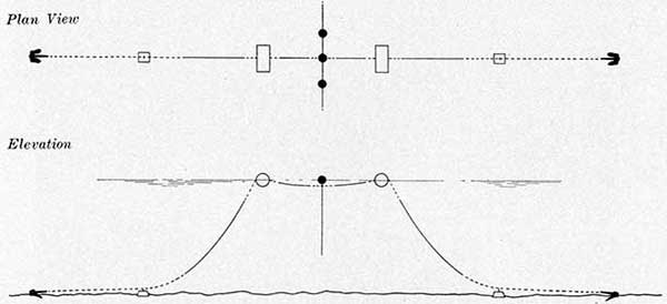
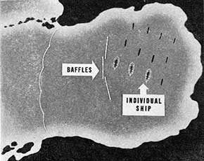
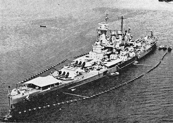
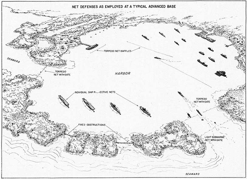
The Individual ship protection nets described in detail in Chapter VII following were developed to answer this need although not until another demonstration had emphasized the need, even at great distances from enemy air bases.
These nets, as described later, consist of spars and torpedo net which fit each ship with its own torpedo barrier when at anchor at a base where such nets are available.
During the period 1939 to the end of December 1941 American net and boom defense activities were chiefly concerned with adapting British designs and experience to our needs, especially in assembling and installing adequate submarine defenses at all major bases.
On December 7, 1941, the Japanese surprise attack upon Pearl Harbor furnished another and
unforgettable demonstration of the need for torpedo defenses at fleet bases. While serious damage was done by bombs, torpedoes were the principal cause of the immobilization of the ships damaged.
Midget submarines which had entered the base, apparently through the open gate, also figured in the Pearl Harbor attack. One of them made a successful reconnaissance of the inner harbor and retired to report the result to its consorts before the air attack was launched. However the midget submarines which took part in the actual attack did not live up to the expectations of their designers, there being no evidence that any of them scored hits.
The Japanese raid upon Hawaii raised two questions concerning nets; whether they could be altered to provide protection against torpedoes fired from inside harbor entrances and whether they could be altered to block midget submarines.
The answer to the second of these questions was self evident. The mesh of the standard submarine net was too large. Accordingly, existing nets were altered to four foot mesh and thereafter new nets were made to the altered size.
Design of torpedo net made up in individual ship protection units was the only possible answer to the most serious weakness exposed by the attack at Hawaii. Chapter VI following records the progress that has been made in that direction. The limiting factors governing design are the necessity for providing sufficient strength to stop the most powerful torpedo without sacrificing the local yield, especially at the top of the net, which experiments suggest to be essential to success. This is not easily done where the nets must be supported at short intervals by spars from the ship they protect. It was necessary to provide a simple and reliable means of opening the nets in order to permit the ship to get under way without delay. And in order to encourage the widest possible use of the nets it was necessary to make them as light and compact as possible.
The sinking by torpedoes of the Prince of Wales and Repulse impressively confirmed the demonstration staged by the sinking of the Bismarck that even the most modern battleship could be crippled. or sunk with torpedoes thereby making the need for improved torpedo nets more urgent.
The British made repeated and determined attacks upon the Scharnhorst and Prinz Eugen, which had taken refuge in French ports but the ships
21
survived both those attacks and the strong airplane attacks made when they successfully retreated up the Channel to their home bases.
During late 1941 and early 1942 the entire German force of heavy surface ships was, concentrated in Norwegian ports as a threat to the Murmansk supply line.
In the Mediterranean relatively large forces of Italian and United Nations surface ships campaigned within short submarine and torpedoplane range of each other until the invasion of North Africa gave the United Nations air control of most of the western Mediterranean.
These salient points of the war have been summarized because they bring out the part played by nets and therefore supply one reliable guide for further development of net designs. The fact that the 'evidence recorded is largely negative does not necessarily reduce its value as evidence.
The importance to the British of destroying the heavy German ships at bases along Norway's west coast is obvious, and the persistence with which they attacked revealed that the British did appreciate that importance.
The circumstances were, in several respects, favorable to attack with submarines which could attack at short distances from their bases and into waters with which they were thoroughly familiar along both the French and the Norwegian coasts.
Yet there is no record of a successful submarine attack upon ships in the German held French bases. And only that by midget submarines, against German ships at Norwegian bases.
Many air attacks and constant reconnaissance flights were made, however.
This indicates that the British submarines, which during the World War at the Dardanelles and in the Baltic, for example, had demonstrated repeatedly their readiness to attack submarine nets, considered the defenses protecting the German ships to be too strong to justify the attempt.
The sinking of four anchored American ships off
Rabat in the course of the North African landing in spite of the presence of numerous craft equipped with modern detection gear disclosed the need for some means of providing protection against torpedoes temporarily during amphibious operations.
It remained for American submarines operating against the Japanese in the Pacific to furnish a striking contrast to the nearly complete lack or results with torpedoes in the European war areas.
Lieutenant Commander Chester C. Smith, according to a published account, with the sea "as calm as a mill pond," sighted Japanese ships in Kerman Bay, at the northeastern extremity of Halmahera in the Moluccas.
"The bay was well guarded by Kawanishi flying boats" the unofficial account runs, "with little patrol craft on duty inshore, around the entrance. Despite the enemy's precautions, Smith could see two freighters unloading inside the harbor." He struck each ship with two torpedoes and retired safely in spite of a depth charge attack.
Later the same officer sank a Japanese tanker in Subic Bay.
According to official reports the Seawolf, followed an enemy convoy into the harbor of Christmas Island in the Indian Ocean where the convoy entered and the, transports promptly began to unload. The Seawolf torpedoed an enemy cruiser and escaped.
On July 4, 1942, an American submarine invaded Kiska Harbor and torpedoed three Japanese destroyers anchored there.
These successes scored during the relatively short course of the war in the Pacific demonstrate what can be done by submarines in the absence of nets. The contrast between American successes against the Japs who do not use nets freely and the few such successes scored in European waters where net protection is very generally provided indicate the importance of providing adequate net defenses whenever and wherever the naval situation permits materials and trained personnel to be provided.
22
RIGGING TORPEDO NET
23
CHAPTER III
The Net Establishment
Mission
To provide the service with net material and facilities.
Developments at sea determine where and when such protection will be required. Requirements are transmitted from the Commander-in-Chief and subordinate commands afloat through the Chief of Naval Operations to the Bureau of Ordnance which is responsible for designing, providing and maintaining the material required.
The full proportions of the net establishment's task are outlined both in space and time by its assigned mission. Materials and specially trained personnel must be available on demand by the forces afloat over areas covering most of the major seas.
Responsibility for the development, procurement and maintenance of net material rests exclusively upon the Bureau of Ordnance. But the success with which the Bureau meets this responsibility must depend very largely upon the lively interest and constant cooperation of all officers, afloat and ashore.
Naval war demands, and is stimulating, a rapid evolution of design, production and distribution of net defenses. In this situation only continuous contact between the Bureau of Ordnance and operating units of the Navy will produce the constant improvement of methods and gear essential to defeating an alert and determined enemy.
Design
As previously outlined, modern net defenses were first developed from the needs of the British Navy during and after the World War. Detailed plans secured from the British constituted our starting point in design.
The Research and Development Division of the Bureau of Ordnance is the clearing house for suggestions
and ideas. It is responsible for examining all ideas for improvements; for sifting out those that are promising; for subjecting them to experimental and service tests; and for producing new designs developed through this process.
Its raw material is the mass of ideas secured from all sources. Its finished products are the blueprints from which all types of nets and net gear and equipment are constructed. When a new departure, for example an improved mooring float, or a lighter and more efficient type of net for some specific purpose, develops promise, it is tested by the Research Division at one of the experiment stations.
Procurement
Aside from actual purchase of materials, a function of the Bureau of Supplies and Accounts, the Bureau of Ordnance must seek out all possible sources of material. It transmits to producers plans and specifications for delivery in the quantities determined by the Chief of Naval Operations and at the times and places fixed by the planning. sections of the Commander-in-Chief and his subordinate commanders.
Maintenance
The Maintenance Section of the Bureau of Ordnance keeps running records showing the location of each item of net material. As directives from the Chief of Naval Operations are received arrangements are made for shipment to the ultimate destination in the exact quantities required. To meet these requirements major shipping centers are located at certain Net Depots where reserve supplies are maintained.
The importance of centralized control of transportation has been repeatedly demonstrated. To meet emergency demands which often arise, the
24
ADVANCED BASE STORAGE
25
FLOAT STOWAGE IN JUNGLE
26
GEAR ON BEACH
27
SEAWALL AND RAMP
28
Bureau of Ordnance must know constantly where every pound of net equipment is. War invariably overtaxes facilities in terminal ports and storage lots. For these and other similar reasons an unneeded and unreported surplus of one type of fitting easily may be overlooked and forgotten to the direct detriment of combat operations.
For example, in one combat area a shortage of -torpedo nets developed. At a cost of considerable delay and sacrifice by other areas the required nets were shipped. Yet shortly afterward when an experienced net officer visited the area he found a generous supply of torpedo nets safely stored in a -warehouse and labelled "Blasting Mats."
This reveals what may and does happen in the absence of close and continual check upon reserve supplies and shipments by one central office which in this case necessarily must be the Bureau of Ordnance, the sole authority in a position to follow the material needs of all net activities and thus anticipate future demands.
The weight and bulk of net equipment complicates distribution, especially overseas transport.
The critical shortage of metals and certain other materials makes it necessary in many cases to get along with old designs and substitute materials in areas where the probability of enemy attack is relatively remote, such as the continental bases.
Depots
The primary function of a net depot is the stowage, assembly, installation and maintenance of net defenses.
The net depot at a permanent base was the initial unit of the net establishment developed. Net depots are the principal points around which net maintenance and training are developed and improved upon to cope with the changing conditions of naval war.
Some of the larger depots have as a secondary function the training of, net personnel for distribution throughout the service. Also, because of the constant need for experimenting and testing new equipment under widely varying conditions, every
NET GEAR IS BULKY
29
well established depot, must be equipped for conducting field tests of equipment.
The typical net depot has developed to perform these functions.
A large paved slab is essential for assembling nets and equipment. It should provide a firm, smooth working surface and should be located alongside a dock or ramp from which assembled nets can be launched.
A certain amount of manufacture of nets is done at most net depots, as well as repairing damaged nets and replacing worn parts. In both cases nets are spread out on the slab where the space makes handling the bulky flotation gear and nets relatively simple.
When new or overhauled net is ready for streaming its flotation is attached, and in the heavier types of net, is either lowered from the seawall or dragged down the ramp.
Net materials, flotation, moorings and nets proper, are heavy and bulky. Therefore, space is important, as well as good transportation close at hand. As one port officer expressed it:
"It's not the weight that matters, it's the cube."
Torpedo nets, packed in neat bundles, occupy relatively little space, while their mooring gear and specially their flotation require far more space for storage and handling than the actual nets. The peg top buoys used for the heavier nets are so large, 13 feet in diameter, that many railroads lack sufficient track clearance to carry them at all.
The elementary fact of the bulk of net equipment is a basic consideration in planning and laying out a net depot.
Both rail and water transportation, as well as several motor cranes of at least 10 tons capacity, are desirable for a large net depot.
The flow of material is from incoming transportation, rail or water, to storage piles and warehouses. As needed the equipment, buoys, shackles, net panels, etc., are hauled to the slab and there assembled into complete nets. As flotation is attached the nets are hauled to the water and streamed.
Floating Equipment
Numerous types of boats and small ships either specially designed for the purpose or adapted from
craft locally available are used in installing and maintaining nets. Buoy boats, tugs, the sectional Quonset barges, lighters, net tenders and small patrol launches all are used in working on the various types of nets. In addition the AKNs which are, in effect, floating net depots, converted from standard Liberty ships are being commissioned.
The most useful craft for installing and maintaining heavy net defenses is the standard navy NET LAYER, shown in the illustration on the next page.
Its most distinctive features are the design of its-bows and the arrangement of the forecastle.
As shown in the illustration, the ship is constructed with a double bowsprit, universally called "the horns" in the net service, and each having a safe working lift, of 15 tons.
Between the horns is a clear, metal sheathed opening through which nets and gear can be streamed or brought on deck.
The catwalk above the opening between the horns provides what amounts to an auxiliary bridge from which the officer controlling the operation can handle engines and winches while directly observing the work going on under the bows.
The forecastle deck is clear back to the double electric winch installed against the forward deckhouse bulkhead. Fairleads are placed well to the sides against the rail so that the entire deck is free for working space. By means of the fairleads, where necessary messengers may be led from the after winch drums as well giving four working lines for any operation.
The electric winches installed forward and aft each have two drums with a capacity of 1800 feet of 1 1/4 inch wire. One officer, with a clear view of the operation, has complete control of ship and working crew. And the gear, often very heavy and under great strain from current, can be brought up well clear of the water where the work can be accomplished with a minimum risk of the minor casualties which often lead to delays and serious accidents.
The horns afford an easy means of carrying a number of the heavy parts of a mooring, anchors, stretcher weights and buoys, while leaving the connecting chain clear for laying. In practice, chain bridles are installed around the bases of each horn providing still another means of transporting heavy gear.
30
CLOSE-UP OF NET LAYER
31
Net tenders are Diesel-electric drive vessels of approximately 1200 shaft horsepower. They displace from 700 to 1200 tons, have a speed of 12 knots, carrying a complement of 4 officers and 44 men and have a cruising endurance of 5,000 miles at ten knots. With these seakeeping qualities they are able to carry efficient net laying gear and experienced net personnel to any area where nets may be required.
For a typical net depot responsible for a large net installation tugs should be provided, to be employed in minor repairs, for towing, replacing buoys and general maintenance.
Buoy boats are indispensable for supplementing the work of the tugs. These may be converted from fishing craft or standard navy motor sailing launches. What is required is sturdy construction, reliable engines, a winch and boom with a good working lift and as much room as possible between engine compartment and bow for carrying net gear.
Another new type of craft, developed primarily for advanced base work, has proved its value in service. This is the pontoon barge. As its name implies, it is built in sectional pontoons which can be stowed aboard ship and assembled at the destination into a large shallow draft barge.
It is powered by heavy duty outboard engines with adjustable propellers and rudders, of 143 horsepower each, designed on the same general lines as the familiar small outboard motor used by fresh water pleasure craft. Its winch and boom are capable of handling 10 tons.
Aside from the sectional construction the pontoon barge is distinguished by handiness. It's two engines, spaced wide apart, which also swing with the rudders, can turn it virtually in its own length and with its clear deck and low freeboard it can handle nets and net gear with ease. Except where strong current and rough water may be encountered it is ideally adapted to handling net equipment.
Improvised Net Craft
War emergency demands forced net personnel to improvise net working vessels out of craft immediately available and before specially designed vessels were available in anything like adequate numbers.
In Great Britain a large part of the net work was done by steam trawlers adapted for use with nets
by installing derricks of five and three ton capacity on the fore and main masts, respectively. Two three-ton gallows were installed on each side and in addition in the bows, troughs were installed, one on each side for handling moorings and heavy weights, each being fitted with rollers and fairleads to the winches.
With these relatively simple alterations the trawlers, already designed to keep the sea in all weathers, gave an excellent account of themselves.
At American net depots similar improvisations bridged the gap between the war's beginning and the time when specially designed net vessels became available. One such demonstration of using the material at hand is worth mentioning here as an example.
At the Naval Net Depot, Tiburon, where an exceptionally heavy Type S installation was required a low powered, covered hay barge was secured. From it a very effective net tender was developed.
The necessary deck house, bridge, crew quarters, etc., are all in one structure placed well over on the starboard side after the fashion of an airplane carrier, leaving most of the deck entirely clear. Although its engines only develop 150 horsepower, this craft has proved extremely useful. She can carry a larger deck load of nets than standard net tenders and because of her unusually large free deck area, can take nets aboard, carry them to their destination, and stream them in shorter time than where they must be towed.
For local use where there is no need to get out into the open sea such craft may be almost as useful as the much larger and far more expensive standard tender designed for deep water cruising.
Net Training Schools
Experience has demonstrated that net depots, especially where they maintain large net installations, are well equipped for training net personnel without detriment to maintenance operations.
The requirements for effective net training have developed out of war experience.
Student officers and enlisted men, many of whom may come to the school almost directly from civil life, must be instructed rapidly and thoroughly in the various types of nets in use. They must be familiarized with the details of net equipment. And particularly they must learn how to assemble,
32
PONTOON BARGE
33
install and maintain nets with their moorings, flotation and gate installations.
Experience has demonstrated that this is much more a matter of practical than of theoretical instruction. The details of seamanship involved in handling complicated moorings cannot be taught from books. The handling of the various types of nets, which often must be laid under emergency conditions, has developed into a specialized field of seamanship where even experienced petty officers must undergo supervised instruction before they can be called fully qualified net men.
And once they are so qualified it is very important that they be kept in the work for which they were trained instead of being diverted into general detail, as happens frequently and thus lost to net operations.
Provided that experienced officers and petty officers are available as instructors, students detailed in working teams to lay, recover, inspect, patrol and repair nets can make rapid progress. And in the process, as a by-product to the direct matter of learning net work, they may, under the best conditions, be indoctrinated for general naval duty as well or better than can be done in a school whose sole function is indoctrination.
This is particularly true where a net depot also operates a fairly large and varied flotilla of net and patrol craft. At the depot on San Francisco Bay, which not only maintains the net line but also operates the gates and patrol craft, student officers can be detailed to actual duty on the various types of craft during their Course. As a result each man has an opportunity to perform all the operations of assembling and laying nets and in addition has his tour of duty in handling all types of net craft.
In learning ground tackle, piloting, watch standing, ship handling and the constantly varying details of net patrol and inspection under all conditions of weather and current, young officers acquire a broad foundation in seamanship which is, after all, the basic naval branch.
Generally speaking the net depot which deals with the widest variety of local conditions, weather, traffic through its net gate, current, depth of water, etc., is best qualified to conduct a school. The performance of new naval personnel processed through such schools with little previous preparation has been surprisingly good.
The object of the course is to develop officers and
men who will be able to report to advanced bases and immediately take up the duty of installing nets without further instruction and often with less adequate equipment and fewer facilities than are available at any continental base,
A survey of the actual continental bases maintained by the American Navy reveals that there can be no such thing as a "standard" net depot. Many depots are maintained along the country's three coasts. They vary widely in virtually every respect, depth of water, strength of current, character of weather, type of net used, length of the installation, amount of traffic, ease or difficulty of material supply and the limits of responsibility carried by the particular depot.
One depot, for example, may be responsible only for replacing worn equipment. Another may have, in addition to this duty, the complete task of operating the net defenses, control of gate and gate vessels and patrol of the net line.
Few general rules can be laid down. The continental net depot must be located where it can receive, assemble and install its nets. It must have adequate space. There is a constant demand for net handling equipment, specialized craft and new materials to be shipped to advanced bases under daily threat of attack. The continental net depot therefore must always be ready to surrender its gear and get along with old or second rate equipment in order that the net units nearest the enemy may have priority.
Advanced Bases
Advanced bases units are the first team of the net establishment. Their mission is that of the general net establishment; to protect moored ships and usually an anchorage against torpedo attack by airplanes, submarines and surface craft.
Every activity of the net establishment is a preparation for the critical moment when an advance base is born. Some morning an advance base officer probably all too conscious of his own short experience is confronted by a mountain of gear on some cluttered landing beach. The entire naval net establishment exists to help him at that moment.
The duty of the advanced base officer is neither as simple or as easy as that of the officer working
34
35
at a well established continental base. From the moment he arrives he is very much on his own.
When an advanced base unit moves in usually it finds materials are somewhere, on the ship on which the unit arrives, on some other ship, or stacked on the beach and buried in the mountains of material for a landing in the face of the enemy. Net craft, tenders, pontoon barges and buoy boats may or may not be available. If they are, almost certainly, many other demands will be made upon them and their crews.
In landing operations such demands always must be met. Net units must do all that they can to further the team effort. Requests to help with other tasks are something of a burden but also they are a recognition of the usefulness of well trained net sailors.
The nets must be installed, however, and experienced advanced base officers all agree that the measure of a net man or net unit's ability is the degree with which he or it can meet all reasonable demands cheerfully, and still put in the nets.
Equipment for advanced base units cannot be standardized. Each operation is designed, planned and equipped to meet the special situation at that spot. Depending upon the type of nets to be used, upon the nature of the base to be established and upon local conditions, the command afloat applies through Operations for equipment not at hand in its area. The Chief of Naval Operations requisitions equipment required from the bureaus concerned, boats, for example, from the Bureau of Ships; nets from the Bureau of Ordnance.
After an advanced base has operated for some
time its actual needs can be fixed with considerable accuracy. But the urgency of the advanced base's need for equipment increases in something like geometrical ratio with the distance from sources. Each added mile of distance from continental rail heads both extends the supply line and _shortens the range of enemy counter-attack.
For these reasons the needs of the advanced base always must have priority over all others in the net establishment.
Floating Bases
Increasingly fluid war at sea has produced a wide demand for what amounts to a floating net depot, equipped to move in soon after the first attack echelon and deliver nets and gear to net laying craft for immediate installation. Also, when not occupied with direct attack operations such craft may be usefully employed in visiting advanced bases, supplementing their repair facilities and delivering net equipment.
The Net Cargo Vessel, AKN, was developed to meet this need.
It is, in effect, a floating net depot and is equipped with specially trained personnel and with cargo capacity designed to deliver nets with the greatest possible speed after a landing operation establishes a foothold.
As a new type of ship it necessarily still is largely in the experimental stage but it promises to be the ultimate accomplishment in adapting net defenses to the highly fluid war being waged in the Pacific.
36
37
CHAPTER IV
Type S Net (Submarine)
Function
To block and expose submarine attack.
A submarine net must either block submarines attempting to enter a port or, if they burst through the net, cause their immediate destruction by revealing them to net patrol craft.
This is the heaviest, most massive net used. It is installed at major bases and ports where concentration of merchant shipping and probability of attack justify the necessarily heavy expenditure of material required in constructing this type of net. War experience has demonstrated that this type of defense, properly installed and maintained, provides the high degree of security from submarine attack essential for a major fleet base where otherwise ships would be particularly vulnerable.
One point regarding nets must be kept in mind constantly. No net or boom yet devised can be effective alone in the sense of being self-sufficient.
Such barriers can provide effective protection only where they are constantly backed up by alert net patrol craft and other defenses equipped to destroy any enemy attacking from below, on or above the surface. Without such support special diving craft, for example, could sever net connections, leaving the base exposed to submarine attack.
The barrier must be so rigged as to permit easy and rapid passage of friendly vessels without exposing the anchorage to enemy action. The net is, in effect, a wire fence securely attached to the ground and equipped with a closely guarded gate. The fence, that is the net proper, is suspended from buoys floating on the surface which in turn are secured at intervals by chains 'running to heavy anchors on the bottom.
The basic elements of a net installation are:
The NET, a fabric woven of heavy wire; The FLOTATION, a system of buoys and floats supporting the net and moorings;
The MOORINGS, the anchors and their connections.
Net Fabric
The standard submarine net is constructed with diagonal mesh measuring eight feet on each side in lengths called PANELS, measuring 300 feet. Nets are tailored to fit the depth of the water where they are to be installed and must reach the bottom without an excessive width which would foul the bottom and possibly impair the functioning of the net under attack.
Two panels married together form a SECTION, the lineal unit used in installing and referring to large net systems.
Construction and overhaul of nets requires a flat, hard-surfaced working platform which in practice for submarine nets, the largest in use, should be at least 350 x 150 feet. It is called a net SLAB, and is fitted with sockets for iron pegs, called PERIMETER PINS, to which the nets are secured during the weaving process.
The following general description of the weaving of a submarine net is given as a typical example. In weaving any specific net the Bureau of Ordnance drawings must be followed in detail.
The vertical width of each panel in meshes, that is, its depth, is determined by dividing the depth of water, less the depth of the net's top below the surface when in place, by the width of a vertical mesh.
In preparing a net slab for weaving a submarine net the outline of one panel's perimeter is marked out on the surface.
Beginning at a top corner the outline is laid off in spaces equal to the diagonal length of the mesh as specified for that net. A half space will be left over at one end of the panel.
38
STRIP OF A NET ON A SLAB
39
Perimeter pins are firmly fixed at the points thus determined.
The headrope from which the net is suspended is called the JACKSTAY:
It is a six-strand, 19 wires per strand, 1 5/8" galvanized steel wire rope with a breaking strength of 190,000 pounds and weighing 4.23 pounds per ft.
The jackstay is cut to 290 feet and is fitted at each end with an open SOCKET:
Because the jackstay is the net's primary strength member, care must be taken to see that the wire is not weakened when fittings are applied and connected.
The jackstay is led out at the head of the slab just clear of the net space.
The bottom and ends of the net are formed by the PERIMETER ROPE, supplied on reels carrying 3,000 feet and weighing 4,500 pounds packed for shipment.
With the jackstay the perimeter rope constitutes the frame upon which the net fabric is woven. It is a six-strand, 19 wires per strand, one-inch galvanized steel wire rope with a breaking strength of 73,700 pounds and weighing 1.6 pounds per foot.
The perimeter rope is passed around the perimeter pins at the two lower corners of the net and secured at its ends to the jackstay just inside the sockets as shown in sketch following.
With the net frame in place the next step is the weaving of the MESH ROPES:
This is a single strand, flexible steel galvanized wire rope consisting of 70 wires and 21 hemp yarns. It is one-inch in diameter, has a breaking strength of 98,280 pounds and is internally lubricated and protected against the action of salt water by saturating the fiber cores with a preservative composition. It weighs 1.8 pounds per running foot and is supplied on reels carrying 3,000 feet of wire and weighing 5,000 pounds packed for shipment.
This special type of mesh rope was developed through experiments which disclosed that a small number of large gauge wires would resist net cutters better than a large number of smaller wires and also would have greater endurance when submerged than the usual six-strand wire rope.
40
Weaving
The first mesh rope, called the KEY ROPE, is started at the upper left corner of the panel and led downward at an angle of 45 degrees to the bottom perimeter pin which is the same number of spaces from the bottom left corner -as there are vertical spaces at the end of the net. From that pin the key rope is led up again at an angle of 45 degrees and so diagonally back and forth across the net frame until it reaches the far end.
The end of the key rope (a) is then secured to the perimeter rope at the top left corner and hauled taut by under-running from the starting point at the first perimeter pin through to the far end of the net. There it is cut and secured to the perimeter rope with three 1-inch WIRE ROPE CLIPS, using approximately five feet of mesh rope for securing.
The second mesh rope (b), is now rove, starting from the first pin down at the left end, up and over the first lead of the key rope, around the first jackstay pin, down to the pin to the right of the key rope at the bottom and so on until the right side of the net is reached, the ends being secured to the perimeter rope as described in the preceding paragraph.
When the net is complete, mesh ropes must cross over and under each other alternately which is accomplished by following the successive steps of the weaving process given on the Bureau of Ordnance drawing.
Securing Mesh Cross Connections
After mesh ropes have been rove and secured to the perimeter rope each mesh is measured with an
8-foot batten and the wires marked where they are to cross.
They are joined at the intersections with FOUR WAY CLAMPS:
set up to 3,800 inch pounds torque on the nuts as measured by a standard torque wrench. When set up in place the clamp nuts are locked in place with galvanized bend-over LOCKING PLATES.
As the intersection of the mesh ropes is the point at which the stress of checking a submarine would first be brought to bear, care must be taken first to see that the clamps are set up evenly and to the required grip, and second, that when the locking strips are bent over the fold is not made any more sharp than necessary- to lock the clamp nuts. If the strips are flattened down too much the galvanizing invariably cracks and speeds up corrosion, which eventually causes the strip to fall away and the clamp nuts to loosen and fall off.
Securing Mesh Ropes to Jackstay
At the jackstay perimeter pins mesh ropes are secured with 1 5/8" WIRE ROPE CLIPS:
41
The wire rope clips operate like fists gripping the jackstay and the mesh rope together. Because of the angle at which it joins the jackstay and the fact that it necessarily carries the weight of the net fabric the mesh rope is under constant and heavy strain at this point. Care applied here in securing a firm and uniform grip in setting up the clip nuts will prolong the life of the net panel in service.
Points to be Remembered in Weaving
EVEN number of diagonals; the second mesh rope must cross alternately over and under the key rope.
ODD number of diagonals; the second mesh rope must cross over the key rope in every case.
After the second mesh rope has been rove, the ropes are rove working in order down the perimeter pins at the left side and are led upward to the top of the net. When the bottom perimeter pin is reached the process is reversed, the mesh ropes working back up the perimeter pins at the left side and leading downward to the bottom of the net. Thus, when the panel is finished, two mesh ropes will lead from each end perimeter pin except the corners.
When completed the panels are brailed as closely as possible to the jackstay and are stopped with wire.
ALL FITTINGS MUST BE FULLY SET UP AND TIGHT.
REDUCED MESH SUBMARINE NET:
Modifications of Standard Design
The advent of the midget submarine made it necessary to reduce the size of the mesh in the standard submarine net.
To conserve material and time this was done with nets already in use by weaving 1/2 inch mesh rope midway between the 1" mesh ropes and parallel to them as shown in sketch, thus quartering each mesh. As shown the 1/2" mesh rope is only brought to the middle of the upper row of standard meshes. Where it crosses the 1" mesh rope four-way clamps of proper size are used.
Square Mesh Submarine Net
Experience has shown that standard submarine nets fail most frequently where the mesh ropes are clipped to the jackstay. The clip, working on both jackstay and mesh rope, tends to cause breakage of either or both at this point.
Tests of the two types of weave do not indicate any appreciable superiority of the diagonal weave over the square with respect to defeating cutters while, for the reasons given above, the square mesh is somewhat more durable in service.
To eliminate the failures mentioned above and at the same time to defeat midget submarines, nets with six foot square mesh are being developed. While this calls for a somewhat less simple method of securing mesh ropes to jackstay, the increased endurance of the square mesh appears to justify the change.
Bottom Nets
Where the depth of water permits, an effective reinforcement of the gate in a Type S net system may be provided with an additional section of net moored across the channel and held in place by submerged buoys at such a depth that the top of the net will be cleared by the deepest draught ships using the channel.
This type of net has several advantages over the standard Type S rig. It is invisible. It effectively closes the gateway, any net's weakest point, against submarines attempting to slip through deeply submerged while the gate is open for surface traffic. Therefore if an enemy submarine should be aware
42
that the net was there it would be forced to attempt the passage at a very shallow depth where the chance of detection would be much greater. And, because the net is held below the surface, the strain upon its parts remains nearly constant, thus eliminating most maintenance difficulties.
A thorough test of a bottom net with frequent inspections establishes its endurance in use, the net having been maintained for 12 months without requiring any maintenance work.
Limitations
Bottom nets can only be used in comparatively deep channels. Being invisible, if parts should fail, in most cases unless a buoy broke loose and came to the surface the casualty might not be discovered until a diver inspected. Also, without reliable means of revealing when a submarine attacked the barrier the enemy craft might free itself from the net and escape without being detected from the surface.
In spite of these limitations where a sufficient depth of water exists a bottom net does render the net system more formidable at relatively low cost in material and effort.
Skirt Nets
(See Chapter IX.)
Flotation for submarine nets, exclusive of mooring flotation, is provided by either 175- or 300- gallon barrel floats or by 3,000-pound spherical floats which are superseding the panels.
The 3,000-pound spherical float takes its name
from its net buoyancy, 3,092 pounds. It displaces 3,770 pounds and weighs 678 pounds; is 58 inches in diameter and provided with fittings for shackling.
The 300-gallon barrel float takes its name from its shape. Its net buoyancy is 2,710 pounds; it displaces 3,210 pounds and weighs 500 pounds; is 51 3/4" in diameter and 49" long.
The spherical floats have greater endurance in service than the barrel type and are replacing the barrels as supplies become available.
This has been demonstrated both by service experience and in special tests. The spherical design is physically stronger and therefore will stand more punishment. Explosive tests also have shown that the spherical floats are less readily ruptured.
The spacing of floats along the jackstay is determined by the depth of that particular panel, i.e., upon the weight to be supported. This is computed according to formulae supplied on Bureau of Ordnance drawings.
Floats are connected to the jackstay with 3/4 inch buoy chain shackled to jackstay clamp as shown in sketch.
43
The standard flotation set forth in Bureau of Ordnance drawings is intended as a guide and is not to be considered in any way as a restriction where excessive currents or unusual conditions are encountered. Mooring, flotation, or other details of the installation must be strengthened where this is necessary to deal with local conditions.
When completed and flotation is attached net sections are towed to the site of the net and attached to moorings already in place.
Moorings
The strength of a submarine net derives from its moorings which, through the jackstay and mooring connections, anchor the barrier to the bottom.
Mooring a net depends upon exactly the same simple principles that govern mooring a ship securely against possibly heavy stresses of current or weather.
Because of the many details of rigging with which net men must deal much apparent confusion
of thought may be avoided if these elementary facts are kept clearly in mind.
A simple illustration familiar to all sailors brings out how the basic principle of ground tackle operates.
An experienced seaman when anchoring where heavy weather or current may be expected always anchors to a long scope.
In calm weather and slack water there may be no strain whatever on his ground tackle. Much or most of his chain lies inert on the bottom. All that he needs to hold his ship under this condition is the weight of the chain between his hawsepipe and the bottom directly under it. But if his chain were firmly connected to the bottom directly under his ship he would have no margin of safety beyond the breaking strength of his chain under sudden stress. With a long scope, on the other hand, he is protected by the fact that any stress applied to his ground tackle will be applied gradually.
The long scope permits the whole chain to function as a spring would function, gradually increasing
44
its resistance to pull as more and more of its weight is lifted from the bottom. This aids the anchor in holding and in addition protects the chain against any sudden, excessive strain.
This principle is used in securing nets and booms. By providing elastic yield the total resistance to either strong current or the thrust of an attacking submarine is vastly increased.
A submarine net, designed to stop the heaviest submarines, depends for its strength upon a progressively increasing elastic resistance.
A typical submarine net mooring consists of two pairs of 6,000-pound anchors laid out at right angles to the net line, one pair on the seaward and one pair on the harbor side of the net.
In order to provide elastic yield against submarine attack without using excessive lengths of chain net designers have used another of the oldest devices of practical seamanship. In the days of sail, captains of fighting ships were forced to ride out heavy weather on a lee shore where the strength of their anchor cables might be overtaxed learned to provide greater elasticity by slinging a heavy gun to the bight of the cable.
The submarine net applies the same principle by slinging heavy iron cubes called STRETCHER WEIGHTS in the bights of their mooring system:
With the addition of the stretcher weights the simplified submarine mooring then appears as shown in accompanying perspective sketches showing submarine approaching and engaging the net.
Between anchor and mooring buoys the stretcher weight operates like a long scope of chain, increasing the resistance of the entire mooring and gradually decelerating the submarine.
This gradual yield under attack also increases the endurance of the Type S installation in service. When exposed to sudden heavy strains by current or storms its inherent elasticity automatically distributes a strain applied to any part through connecting members.
The system is designed to distribute heavy loads throughout the entire installation. Therefore, great care is essential in installing and maintaining every link in the system connecting the individual mesh rope to the bottom. Only such care will attain the equal strain upon all parts which is the traditional mark of any good ship or sea-going organization.
Details of Mooring
Beginning on the bottom where a mooring is secured to the ground the typical Type S mooring consists, as previously stated, of four 6,000-pound stock-less anchors, two on the seaward and two on the harbor side of the net line.
They are laid out as shown in sketches, at right angles to the net line, care being taken to make sure that ground chains are set up fully taut as laid.
Standard open link 1 1/2" wrought iron chain is used.
The stretcher weights used in the heaviest installations weigh approximately 18,000 pounds. As previously noted they are simply heavy iron cubes fitted with bails for attaching into the mooring system.
45
46
Flotation for the typical Type S mooring consists of one PEGTOP BUOY on the seaward side:
two WATCH BUOYS: These latter, while not essential to the mooring, are very useful in maintaining it. They are used to suspend pendants secured to each end anchor of the mooring. Any available buoy may be used provided that it will support a pendant sufficiently strong to break out and lift the
anchors where it is necessary to restretch or relay the mooring.
For purposes of simplicity the single line Type S installation has been described, with the exception that the mooring described is that provided for a double line net or for one of the combined nets frequently installed. The double line is used when the greatest attainable security against submarine attack is required.
Experience also has revealed that where current is high the four-anchor system is require to hold a single line of net. For these reasons the four-anchor moorings usually are installed and if a second line of net is required later no change is necessary in the mooring system.
Under some conditions such as bad holding ground or strong current, concrete anchors may be used in place of those described above. These derive their holding power primarily from sheer weight and are made as heavy as practicable with due regard for the relatively heavy loss of concrete's weight in water, i.e., 40% as compared with 12% for iron. One type of concrete anchor which has proved successful is a four-sided, truncated pyramid. In order to increase its holding power on a soft bottom this anchor is cast with heavy cleats similar to those on football shoes designed to sink into and grip the bottom. These concrete anchors used with nets are familiarly known as CLUMPS.
Installation
The laying and installation of nets in general will be treated later. However with respect to submarine nets the importance of a practical knowledge of seamanship and especially of ground tackle cannot be too heavily stressed.
Bureau of Ordnance drawings set forth the details of assembling and laying each type of net. Owing to the varying conditions with which net personnel must deal and the almost limitless number of specific and practical problems which may be encountered, especially in laying heavy net systems, no set of printed instructions can take the place of actual experience in laying and in maintaining nets, both under the supervision of experienced officers at training depots and, later, in actual service afloat.
In a field as eminently practical as this, written instructions are at best a poor substitute for actual
47
manual work with nets and gear. The effective use of nets has become what amounts to a craft within the Navy. The success with which large numbers of young officers without previous experience have developed into efficient net officers demonstrates the wisdom of relying, in practical details, upon word of mouth instruction and, what is even better, upon actual demonstration.
The Bureau of Ordnance will consider actual
exercises with full scale gear the primary means of instructing new personnel. Net work is exacting, but, as far as principles are concerned, is based upon the elementary rules of ground tackle, ship handling and seamanship in general. The proper application of these rules makes the heaviest demands upon net officers. Their effective use can be mastered only by actually assembling and installing fittings and nets.
48
49
CHAPTER V
Type I Net (Indicator)
Purpose
To indicate the exact position and movements of a submerged submarine.
Application of the elastic yield principle introduced what might well be called the modern era of net defense. But, as previously noted, even in the British Isles and their surrounding waters, with their relatively small area, the first World War revealed that nets then in use were too expensive, heavy and bulky for a global war of movement. Advent of depth charges, asdic, and other means of detecting and destroying submarines, that is of countering the submarine's advantage of invisibility, tended to obscure the need for a lighter, more portable submarine net.
But when naval war of movement spread all over the Atlantic, Pacific and sub-Arctic regions the demand for secure operating anchorages at many points no longer could be ignored. That imperative tactical need produced the second great advance in net design, relatively compact, light indicator net specifically adapted to a global war of movement.
An indicator net is not designed to stop a submarine but to expose its presence and exact position. Instead of being a physical barrier it functions as an advanced screen for patrol craft which are, in turn, responsible for destroying enemy submarines invading their assigned area.
To do this the indicator, net must be sufficiently strong and secure to remain in position under all conditions of current and weather. If struck by a submarine any of its sections must hold together while being towed through the water at the maximum speed of a submerged submarine. And, when attacked, any section of the net must drape itself on the submarine in such fashion that its self-contained signal apparatus will reveal the submarine's position continuously.
As its British originators explained, the principle
is to provide a frame, suspended in the water by suitable flotation, containing sections of net which when attacked by a submarine become detached from the frame, remaining attached to the submarine and indicating its position by flares towed behind the net.
Because the indicator net is not designed to stop a submarine its fabric is woven of much lighter wire and it uses lighter moorings and flotation than the Type S net previously described.
Indicator nets are equipped with two, distinctive devices in addition to the net fabric, flotation and moorings, the basic elements common to all nets.
One of these distinctive devices automatically releases a section of the net from the net line and moorings when attacked by a submarine and the other provides a conspicuous signal betraying the position of the underwater craft as it moves through and beyond the net line.
The detached section of net then becomes simply a means of attaching the warning signal to the attacking submarine thus furnishing a guide to the attendant patrol craft.
Indicator nets are made in several weights. All of them perform in the same manner, the heavier nets having a greater endurance under adverse conditions, the lighter being much more easily handled and requiring far less stowage space for shipping.
The lighter nets, therefore, are more in the nature of temporary nets which can be laid in relatively large quantities as a temporary protection while heavier types of net are being assembled and installed.
One other distinctive feature characteristic of indicator nets should be noted. Type S nets are tailored to fit the depth of water where they are to be installed. Indicator nets are made in panels fifty or sixty feet deep. Where necessary, two, three or four such panels may be joined in depth into one net section. And while the Type S nets are
50
LIGHT SUBMARINE INDICATOR NET
51
given the necessary number of vertical meshes to reach the bottom without fouling it, with indicator net the requisite depth is secured by brailing and stopping the lower part of the net so that it will just clear the bottom.
LSI-Light Submarine Indicator Net
This net is a typical example of the indicator class, and is being used more and more widely in the service. The fabric is woven on a net slab as in the case of the Type S net, using side ropes of the same wire as the mesh rope, on perimeter pins and taking the same means of insuring that the mesh ropes pass alternately over and under one another. The corners of the panel are finished off as shown in the sketch with one-half inch wire clips.
Mesh ropes are secured to the side ropes with one-half inch wire rope clips as shown in sketch.
The mesh rope, the basic material of the net, is a one-half inch version of the one-inch, single strand, galvanized steel wire mesh rope used in the Type S net, in this case woven of 30 wires and 7 fibre yarns to provide internal lubrication. Mesh
ropes are secured where they cross by means of one-half inch clamps.
They are woven with four-foot diagonal mesh into panels 50 feet deep and 210 feet long. But, depending upon the depth of water, the section may be one, two, three or four panels deep.
The upper panel is equipped with a 7/8-inch jack-stay used in the Type S net, i.e., it is a 6 x 19 galvanized high grade plow steel wire rope. This is supplied in four jackstays of 52' 3" lengths equipped with closed sockets at each end and jointed at the center of the section with shackles and a 1 1/4" x 7 1/2" I.D. ring, as shown in sketch following:
One of the distinctive features of the indicator net appears in securing the mesh ropes to the jackstay. This is done by means of fittings designed to free the net section from the jackstay at a predetermined stress.
38 of these fittings, called BURSTER CLEVISES:
clip the meshes to the jackstay. When the parting load is reached they release the meshes from the jackstay. Thus when a submarine engages the net the section tears away from the jackstay and drapes
52
itself around the submarine's bow, diving rudders clearing lines, and other projections.
Where additional panels in depth are required these are joined at each mesh by means of 1/2 inch FOUR WAY CLAMPS 42 of which are used to secure each additional panel to the section:
The exact bottom depth required is secured by brailing and stopping up the bottom of the section.
Flotation
Standard 3,000-pound spherical steel floats previously described are used throughout in LSI installations, the number required for each section being determined by the depth of water. This flotation is indicated on the drawing for that type of net supplied by the Bureau of Ordnance.
Spherical floats are attached to the net by means
of three links of 3/4" open link chain, ring and shackles.
The device which reveals the attack when a section of net is detached from the net line is known as the INDICATOR FLOAT.
For lighter nets a light indicator Mark 2 has been developed.
This is a light sheet steel pontoon containing a reel with 300 feet of 1/8 inch towing wire, a water tight flotation chamber and a pot of calcium chloride and calcium phosphide which performs the same function as the smokepots used to guide recovery of torpedoes fired in practice. The smoke-pot is sealed by two TEAROFF STRIPS, which are torn away as soon as the reel begins to unwind. The indicator float is housed in a cage which is firmly secured to the upper panel of the section near its end and so placed that the indicator rides just below the surface of the water. The cage protects the indicator from damage while riding on the net. The indicator float is secured to its cage by means of a light spring which holds it firmly in place with a 150 pound parting clip.
Action of Indicator:-Under normal conditions the two indicators at the ends of each panel ride in their cages just below the surface.
The cages being held to the jackstay by 2 BURSTER CLEVISES: When the submarine contacts
53
the net the strain just parts the clevises holding the cage to jackstay then trips 150 parting clips securing float in cage. This:
(1) Permits the reel to revolve.
(2) Strips the tearoff and admits water to smoke-pot.
(3) Releases the indicator float from its cage.
Almost simultaneously the two burster clevises part. As the towing reel revolves the indicator
itself remains attached to the jackstay by its 450 pound parting clip.
Meanwhile the smokepots are ignited sending up flame and smoke at each end of the panel attacked. When the towing cable has unreeled 300 feet the full strain comes on the 450-pound parting clips and they trip, releasing the indicator floats to trail on their towing wires behind the submarine.
Moorings:-One of the principal savings of shipping space and weight made possible by the use of indicator nets derives from the much lighter moorings required. This is because the mooring is merely required to hold the net in place against the current until the parting fittings release it. The moorings are not required to absorb the submarine's energy. As previously noted, because the net itself is much lighter than Type S nets it does not impose as much resistance to the current.
The Type LSI net is presented in detail as the basic and most important representative of its class. The principles governing indicator nets apparently have fairly well crystallized. But because of the varied demands of global war and the many new ideas developing from practical experience afloat frequent new modifications will and should appear.
Type LI:-This net is a light variation of the
54
ACTION OF INDICATOR NET
55
Type I net designed for more temporary installations or for use where it is necessary to cover much larger areas than could be covered with the quantity of Type I net that could be transported with a given cargo capacity.
It carries the advantage of lightness and simplicity one step further than the LSI. Therefore it can be laid with lighter, smaller boats and by a much smaller force of men.
It operates in exactly the same way as the LSI. And, like the preceding type, it is useless without an alert and strong patrol force on the spot ready to act upon the information it produces. Quite obviously the endurance of these nets against weather and corrosion diminishes as the weight decreases. If that were forgotten the value of all types of indicator nets might be discredited not only to the general service but to trained net officers.
56
57
CHAPTER VI
Type T Net (Torpedo)
Function
To fence out torpedoes.
The torpedo net does this by:
(a) Creating a continuous barrier across the entrance of a harbor.
(b) Individual ship protection units so placed as to stop torpedoes before they are near enough to damage a ship if they explode.
(c) Non-continuous baffles which will catch and stop any torpedo fired at the area to be protected but which will permit the passage of ships without the use of a gate.
As the above indicates the torpedo net is tactically more flexible than the other types. Also it is the only type of net which can afford protection against torpedoes dropped from aircraft.
A torpedo, as compared with a submarine, is a small, light craft moving with a relatively high velocity. It is the inertia of a moving submarine, deriving from its weight and speed, which taxes the strength of the submarine net. Owing to the size of the submarine and the design of the submarine net the stress of the submarine's impact is immediately diffused through the net structure. Even if some of the mesh ropes first struck part, because of its structure the net still can entangle the submarine and overcome its inertia of movement.
The torpedo, on the other hand, embodies an entirely different problem for nets. It arrives at the net with a high degree of kinetic energy which must be absorbed smoothly by the barrier if the torpedo is to be stopped without penetrating. At the critical instant of impact, because of the small diameter of the warhead nose and its high velocity, the total energy of the 300 h.p. torpedo concentrates upon one element of the net. If that element fails the net is defeated.
The fact that torpedoes may carry net cutters imposes another demand upon nets. However, as
far as is known no efficient net cutter has yet been developed without impairing other qualities of the torpedo. Because of the practical difficulty of providing very elastic yield heavier material than would otherwise be required must be used, with a consequent increase in the weight and bulk of torpedo nets.
This has been counteracted, in part, by using a method of weaving applied only to torpedo nets and also by leaving the bottoms of torpedo nets free to swing forward and upward around the headrope as an axis when the net is struck. Finally, unless torpedoes are equipped with influence type pistols, the vertical danger space corresponds with the draft of the ship to be protected. Therefore the net only need extend in depth as far as the keel line of the deepest draft vessels to be protected.
These general considerations govern the design of torpedo nets. The dominant one of them is the concentration of the torpedo's entire energy of impact upon one single net element. This is responsible for the distinctive feature of torpedo net construction.
Net Fabric
The distinctive feature of the torpedo net is the GROMMET:
58
In the Mk I torpedo net panel this consists of 30', 9" of steel wire .2254" in diameter laid up into a single closed strand with the ends buried within the strand and held by the spring of the wire.
The finished grommet is 16" in diameter, is 7-ply, that is, it is laid up with six turns over one, and has a breaking strain of 46 tons.
So far no means has been found for doing this mechanically. Each grommet must be woven into the net panel as the grommet itself is being made. Because high tensile strength steel wire is used only carefully trained men can weave torpedo nets with any speed. Careless or poorly trained men may be seriously injured if the wire is permitted to spring out of hand.
Working in pairs trained men can turn out from 12 to 20 grommets an hour, the tools required being
special grips, and a gauge to size the grommets.
As the weaving of the net develops, each grommet finally is passed through six other grommets producing a fabric much like the chain mail armor used in feudal days.
This interwoven mesh system provides the local yield vital to the effectiveness of a torpedo net. When the torpedo strikes the force of its impact is expended in stretching, that is in elongating, the grommets, each grommet rendering against the adjoining grommets. In distributing the stress to other grommets the particular grommet attacked thus relieves itself of a large part of the load. The loose weave of the net absorbs the stress gradually, transmitting it through the relatively large bearing surface provided by the interlocking grommets. As
59
there are no rigid clamps or narrow fastenings in the torpedo net structure the risk of the fabric being severed under stress is very much reduced.
Headrope
When completely woven the panel is secured to a HEADROPE:
A torpedo net panel is 72 feet long and either 30 or 40 feet deep and is made up for shipment as a BUNDLE, measuring 13'-4" by 2'-6" by 4'-0" and weighing, for the Type T net, 9,177 pounds.
As shown in sketch the ends of a panel differ by the protrusion of half a grommet in odd numbered rows.
Panels are married into sections with shackles. Sections are not shackled together, but are overlapped.
In addition to the local yield provided by the grommet weave a section of torpedo net, when struck by a torpedo, acts as a plane surface freely suspended from a horizontal axis. The net swings upward and away from the imposed force.
The nearer to the net's bottom the torpedo strikes, the less rigid the resistance to the torpedo. Here as in other types of nets the basic principle of elastic yield rather than rigid resistance applies.
Flotation
The Bureau of Ordnance drawings include tables
showing the kind and quantity of flotation required for torpedo nets under the various conditions which may be encountered. In view of the fact that any one of several standard floats may be used with this type of net and that it often is necessary to use any type at hand it is not practicable to announce any strictly standard type of flotation. In general the spherical floats appear to be most efficient and as far as is possible without wasting equipment already at hand floats of that type promise to replace the others.
Experiments with torpedoes have brought about another distinctive feature of torpedo nets. A certain proportion of torpedoes fired run on or very near to the surface. A net suspended from the bottoms of its flotation buoys necessarily must hang about three feet beneath the surface. Therefore a net so suspended would afford little or no protection against a surface shot.
When this danger was first realized torpedo nets then in use were reinforced with small sections of net rigged between adjacent floats and hung from an upper jackstay connecting the tops of the floats. These sections, called curtain nets afforded a quick means of adapting the nets then in use without raising the entire panel enough to bring its top above the surface but at the price of
60
lifting the bottom of the net above the bottom of the danger space.
Obviously it was necessary to make the torpedo net a continuous barrier extending from the bottom of the vertical danger space to or above the surface, i.e., the tops of the floats. This now is done by using a double headrope and attaching the net to
each float at both its top and bottom and extending the net to a depth of at least 35 feet.
This has produced the 40-foot net panel. Allowing for some vertical sag caused by current this gives an effective net depth of approximately 35 feet and extending up at least to the surface even at the low points midway between buoys.
61
62
A point regarding extending the net above the surface is worth noting here. Tests have demonstrated that the net is weakest where it is least free to swing with the torpedoes impact, i.e., at and near the headrope. Therefore when the curtain nets or other means of splicing the net are used great care must be taken to insure that the top of the net is at least as strong as the lower levels.
The Type T torpedo net is heavy. Where deep water and strong currents are encountered virtually the same anchorage used with Type S net may be necessary.
The mooring used with Type T-3 net is typical of those used with torpedo nets under average conditions. The moorings, both end and stream, consist of 6,000-pound concrete anchor backed by 6,000-pound stockless anchors as shown in sketch below.
From the concrete clumps the mooring chains lead to Mark II buoys as shown in sketch.
Net flotation and mooring assembly are rigged as shown in plan and elevation sketches below.
This is a typical Type T mooring assembly but as previously noted the size of buoys used and the types may be varied widely according to materials available and local conditions. Mark II buoys may or may not be used at the net line of the trot.
Because of the threat of a surface run, sag in the top of the torpedo net must be avoided. Therefore every care must be exerted to make sure that buoys are not overloaded and that they are all
watching. A drop of a few feet in the top line of a panel might make all the difference between a successful attack and a triumph for the net defense.
Installation
After sections of torpedo nets are assembled they are towed to the site where they are to be installed. Special care should be taken to see that grommets are not distorted or strained in handling not only because of the direct danger of weakening the grommet but because if grommets are twisted out of shape the entire functioning of the net under stress may be altered. In, a net where one grommet takes the total strain at the moment of impact it is essential that no distortion occur.
The net described is the typical installation used for completely closing the entrance of a port or an anchorage. When provided with a gate, to be described later, it is a relatively permanent installation which, given careful maintenance, should endure over a long period. When effectively patrolled this net should also reveal a submarine attempting to penetrate it under the surface. In shallow water the Type T net affords a considerable degree of protection against this form of attack. It is used extensively for the protection of remote bases where the water is not sufficiently deep to permit the submarine to dive completely under the net.
63
Baffles
Torpedo nets may also be laid in broken lines as shown in sketch to intercept any torpedo fired at the anchorage to be protected without requiring the maintenance of a gate which always absorbs additional vessels and personnel and is to some extent an interference with traffic into and out of the port.
Aside from the fact that there is no gate and the net is not a continuous barrier the torpedo baffle presents the same installation and maintenance problems as the standard Type T installation.
It is just as important to keep in mind the limitations of torpedo nets as to know their tactical possibilities.
The Type T net, properly installed and carefully maintained, will stop the best torpedoes now in use. The torpedo net is an effective barrier as far as the particular line it occupies is concerned. It closes the entrance of a port to torpedoes fired from beyond that line. But that is all that the torpedo net so installed can do.
The development of the torpedo plane has created another very serious threat to anchored ships which neither of the types of installations so far described can counter. Aircraft can fly over any net barrier unless stopped by fighter planes or some other additional protection, and drop their torpedoes on the inner side of the net. They can entirely ignore any barrier on the water until
they have reached a point very close to the target vessel. The Japanese attack upon Pearl Harbor is the classic example of how easily this may be done.
But entirely apart from the defensive gunfire of the target ship and other tactical considerations there is a limit to how far a torpedo plane can shorten the range before it drops its torpedo.
That limit is imposed by its torpedo. Before it will detonate it must arm itself. It is armed only by moving a certain minimum distance through the water. Until it is armed its detonator will not function, that is, it will not explode against the target ship. For torpedoes now known the minimum arming distance is at least 150 yards.
Another peculiarity of torpedoes at the beginning of their run has a bearing here. When first launched, especially when dropped from a considerable height and moving forward with a high residual velocity derived from the speed of the plane they do not instantly assume the depth set on the dial. An appreciable interval is required for their depth engine to take charge and even then the torpedo only reaches its assigned level in a series of dampening vertical zig zags while it is moving through the water.
The result of these two factors is that there can be no great chance of exploding a torpedo against a target ship unless it begins its water run at least 100 to 150 yards away from the target. If an efficient torpedo net can be maintained well within that space and around the ship the latter can be rendered relatively secure against torpedo attack.
The ISP, INDIVIDUAL SHIP PROTECTIVE NET has been developed for this purpose.
Another arbitrary factor affecting ISP Nets must be kept in mind in using this type of net. The possibility of a torpedo exploding in a net always exists. If the net were placed too close to the ship it might fail even if it stopped the torpedo. With these considerations in mind and applying a liberal factor of safety the ISP installation was designed to be installed at a distance of 60 feet from the ship.
A typical ISP installation uses standard Type T net either 30 or 40 feet deep depending upon the draft of the ship to be protected and suspended from floats held out from the ship by six Mark 2 SPARS:
64
INDIVIDUAL SHIP PROTECTIVE NET
These spars are steel spur shores made in two sections for convenience in transportation to be joined in the middle when assembled with eight bolts as shown in sketch. They are fitted at each end with metal backed wood bumpers for bearing against the side of the ship and for connecting to the net jackstay. Where spars are available protection for individual ships can be provided using standard panels of Type T nets. In a port exposed to enemy attack, panels for ISP units may be kept ready in the water and with properly trained net personnel can be installed around a capital ship in approximately 20 minutes.
When not in use for individual ship protection panels of ISP net may be placed as additional baffles supporting the primary protection of the anchorage, provided that moorings are available. Here, as in other situations where combat may be expected at any moment, the importance of specially
trained net personnel is self evident. Officers, petty officers and men thoroughly drilled in the evolution can install ISP units in a small fraction of the time that would be required if trained personnel, especially trained petty officers, were not available.
Variations
Where conditions are favorable the torpedo net can provide complete protection against the submarine's primary weapon and also can nullify the threat of the air-borne torpedo. It probably ranks first in importance among the various types of nets today.
Therefore its limitations are of prime importance. The tactical limitations of the various types of nets are fairly clear.
65
The standard Type T installation closing the entrance of a harbor will stop torpedoes. But it furnishes virtually no protection against air-borne torpedoes, none whatever except that a ship able to lie within 75 to perhaps 200 feet from a line of torpedo net would be protected from air-borne torpedoes fired from the direction of the net. There is no certainty that a T net will stop a submarine. Then, in very deep water the Type T is no obstacle to a submarine diving below forty feet, really, of course, below something like 75 or 80 feet, with periscopes housed.
Because the Type T net line usually must be established some distance from the anchorage to be protected, an enemy could attempt to nullify the net by sinking its flotation from the air with greater chance of success than in the case of close-in individual ship protection.
Baffles offer adequate protection against torpedoes fired at ships moored behind them. The possibility of successful angle fire exists, but it is too remote to have much practical importance. The baffle system is open, however, to penetration by a submerged submarine commanded by an expert-an extremely lucky pilot, equipped with local knowledge. It uses about 50% more material than the closed net line. This system, more than either of the others; is dependent upon the vigilance and efficiency of other defense measures such as underwater sound devices.
Individual ship protection offers perhaps the most absolute protection of all against torpedo attack, where there is time, material and personnel for installing it. It does not, however, protect against attack by devices like the Italian "human torpedo",
the limpet mine or any similar attack directed by one or more men able to approach under the bottom of the net. While ISP protects a ship from airborne torpedoes it offers no defense against bombs dropped from the air, the other type of air attack. And because with the most efficient release gear attainable the nets still are an embarrassment to a ship wishing to get under way at once to dodge bombing from the air, neither net officers nor ship commanders can afford to overlook that tactical limitation of the ISP.
But the primary limitation in increasing the effectiveness of torpedo net protection is not tactical but logistic.
Torpedo net is massive, weighs a great deal and is bulky. Also because it must be made by hand, supplying it in quantities is a slow, costly process.
Taking the lesser of these defects first, efforts to produce efficient torpedo nets without handwoven grommets have failed so far, although there is some reason for believing that this may be done eventually.
In the field of reducing weight and bulk progress has been made. And the principal variations from the standard type of torpedo net stem from that direction, all dependent upon development of a net which will stop a torpedo and still weigh materially less than the original.
Here the controlling factors appear to be susceptible to definite measurement. A large number of actual tests with torpedoes fitted with practice heads fired against torpedo nets have demonstrated that, when newly installed, the standard Type T net, using .2254 wire, probably is heavier than necessary, at least when new.
66
MOTORBOAT BOOM
67
CHAPTER VII
Type B Boom (Motorboat Boom)
Purpose
To block motor torpedo boats attempting to attack moored ships.
High speed wood hulled motor torpedo boats of very shallow draft have successfully attacked ships moored behind nets and minefields, relying upon darkness and their speed to elude defensive gunfire. Especially in narrow waters such as the English Channel, the Adriatic and the Southwest Pacific island areas the potentialities of such attack have been widely advertised.
The motorboat boom was developed to counter this threat. Because speed is its principal and virtually its sole protection, the CMB is built with an extremely light wood hull. The motorboat boom is aimed at this weakness.
The history of boom obstructions has repeatedly demonstrated that barriers of this sort which depend upon weight and rigid resistance tended to be either so heavy and costly that they could not be widely used or to be so weak that they failed when attacked. War experience proved, as noted previously, that the elastic yield-arrestor gear principle was essential in such obstructions.
Development of motorboat booms followed this pattern. When coastal motor torpedo boats appeared along the Flanders coast and in the English Channel during the World War a line of heavy baulks strung on chain sufficiently strong to stop any motorboat was proposed, to be installed across the Channel. Difficulties, principally with current, soon caused the abandonment of this entire "Dover Barrage" project.
Experience with other forms of defenses had brought out the importance of elastic yield which could not be effectively provided with extremely heavy, bulky baulks. The almost complete absence of "give" in the Dover design of boom appeared to be a principal cause of breakage of the boom under stress of current. But the mechanical difficulties of providing gradual elastic yield with such a heavy
structure were not solved.
The present type of motorboat boom developed out of those early experiences. While probably not suitable for a project as ambitious as spanning the English Channel it has proved reasonably effective where installed correctly and under suitable conditions.
Its baulks and jackstays are fitted with heavy spikes designed to rip out the bottom of any light wood craft attempting to break it by ramming or slide over the barrier by sheer momentum. This armed type of motorboat boom is designed, in other words, to force the motorboat to destroy itself.
In effect the boom is simply a means of holding the spikes poised in position sufficiently firmly to be sure they will not be thrust aside without rupturing the attacking boat's hull. But the boom must not be so firm that the action of current upon the bulk of its baulks will overtax and break its jackstays or connections. These were the limits within which its designers were forced to work.
The distinctive feature of the Anti-Motorboat Boom is the BAULK:
As shown in the sketch the standard baulk is a heavy iron-strapped wood and metal tank fitted with eye bolts and links for connecting the boom jack-stays, two pairs on top and one pair across the center line of the bottom. Two watertight iron tanks occupy the interior of each baulk to provide flotation.
68
Length in direction of attack
10'-6"
Width in line of boom
6'
Depth
3'
Total displacement (sea water)
14,100 pounds
Total weight
8,500 pounds
Net buoyancy
5,600 pounds
A buoyant filler has been adopted to replace the tanks.
The baulks are connected by two upper and one lower 1 5/8 inch jackstays with their long axis normal to the boom line, distance between baulks, center to center, being 24 feet, with the baulks spaced 18'-1 1/2" apart, inside dimensions.
Each baulk is fitted with four steel SPIKE CUTTERS:
The spike cutters are fitted at each corner of the upper surface pointing to seaward.
Between the baulks each of the upper jackstays is fitted with four STAR CUTTERS: These are
spaced four feet apart. Thus any motorboat striking the boom will be engaged by at least two star cutters or spikes.
The upper jackstays, when installed, are spaced about nine feet apart. Where baulks tend to capsize the difficulty sometimes may be eliminated by a staggered connection. One line of jackstays connecting the centers of the baulks, the other connecting the harbor and offshore ends of baulks alternately.
Jackstays between the baulks must be cut exactly to uniform length in order to distribute stresses equally among them. They are connected to baulk ringbolts with sockets and shackles.
A standard section of anti-motorboat boom is 561'-8 1/2" bearing length and is made up of 24 baulks.
Moorings
Flotation for the heavy moorings required with motorboat booms is provided by Mark 2 PEGTOP BUOYS:
Displacement
48,100 pounds
Total weight
12,800 pounds
Net Buoyancy
35.300 pounds
Three pegtop buoys are provided for each mooring which consists of four 6,000-pound stockless anchors, two at each end of the mooring, and one stretcher weight suspended between the two. seaward buoys to provide the elastic yield essential to keeping
69
the jackstays taut at all stages of the tide. A four ton stretcher weight is used for depths of water up to 36 feet. Beyond that depth 8-ton stretcher weights are employed. A diamond bridle is used to form the connection between sections, as shown in sketches below, star cutters being fitted on bridle jackstays.
The shore ends of booms may be secured with dolphins, concrete blocks or some other form of fixed obstruction. This is essential wherever shallow water makes it impossible to carry the boom directly to the shore line.
As in all other forms of obstruction a careful continuous patrol of the line is essential as otherwise crews of motor torpedo boats may easily sever the boom with wire cutting apparatus and attack with impunity as was done by the Italians at Trieste during the World War.
Limitations
While this type of defense has proved effective under favorable conditions it is important that its limitations be kept clearly in mind.
It is designed to sink wood hulled motorboats attempting to force a passage and will do so. But
tests have proved that it will not stop steel hulled boats and landing craft equipped with adequate propeller guards. And it can be broken readily by any large ship such as a destroyer.
Its effectiveness depends directly upon keeping the jackstays taut and the star cutters in a position to puncture the hull of attackers. This demands great care in assembling the boom and constant watchfulness by patrols in order to detect and correct any sagging of flotation or slacking of the boom from dragging moorings or other causes.
The weight and shape of the baulks creates problems where strong current is encountered which have not yet been entirely solved without increasing the weight of moorings to a point where the booms can only be installed, under difficult conditions, at places of the greatest military importance.
However, where Type S or Type T nets are being installed it is possible to combine the motorboat boom with the nets with only a nominal increase in the total weight of the installation owing to the fact that the nets can be floated from the baulks. This will be treated in more detail in the chapter following.
In general owing to the bulk and weight of the motorboat boom it raises so many problems of shipment,
70
installation and maintenance that it is not well adapted to use at great distances from sources of supply. It is used where the probability of attack by light motor torpedo boats is so great as to justify the relatively great effort and expense required for installing this type of defense.
Adaptions
In emergencies where attack by motor torpedo-
boats is anticipated an approximation of a motorboat boom may be created by assembling spherical floats on double jackstays and equipping the jack-stays with star cutters.
Such a barrier, if the buoys are kept watching and the jackstays are taut, constitutes a formidable obstacle to light wood hulled craft. As previously mentioned methods of using motorboat booms in conjunction with other types of barriers will be discussed in the chapter following.
71
This page is blank.
72
73
CHAPTER VIII
Rigid Obstructions
Where it may not be practicable to use one of the forms of nets or booms it still may be necessary to close a channel to torpedoes, submarines or surface craft. This situation arises, for example, where a channel not required for navigation can be closed most economically by a rigid obstruction or where, owing to shallow water, nets or booms would not function effectively.
In such instances the obstruction must be designed specially to suit the particular situation, using the materials most conveniently available. Generally speaking one of five types of rigid obstructions may be made to serve.
Cribs
These are heavy structures built up from the bottom in the form of boxes of the heaviest timbers available and ballasted with rock or concrete or both. Between them nets or heavy wire lines are rigged secured to heavy concrete counterweights serving to keep the barrier taut and to provide yield under attack.
Where the danger of motor torpedo boat attack exists either a baulk line or jackstays fitted with star cutters may be used.
Concrete Blocks
Where time and cost are not controlling factors heavy tetrahedronal concrete blocks have been cast and fixed in shallow water with their bases joining. forming a semi-breakwater across the channel to be blocked.
The length of time required for installing such an obstruction and the relatively high cost are serious objections. Also the appearance of the midget submarine raises the possibility that such an obstruction sufficiently massive to block a full size
submarine might not be sufficiently dense to stop a midget.
Steel Hurdles
Hurdles, constructed of steel rails, have been developed in Great Britain for use in such situations, being lighter, less costly and easier to install than other forms of rigid obstructions. They may be used where, owing to the strength of current, it might be difficult to keep blockships, the usual form of emergency rigid barrier, in place.
Two types of hurdles, a heavy and a light, were developed by the British Navy, each made in two sizes for depths of four and nine fathoms, respectively. One hurdle barrier, laid in Clestron Sound, for example, was 1,770 yards long and used 108 hurdles in depths of water from six to ten fathoms. About 3,400 tons of rails were used for constructing the barrier. Three small coasting steamers were employed for nine months in transporting materials, assisted by several tugs, lighters and smaller craft.
Another tubular type of hurdle was developed by the British primarily for use with torpedo net in shallow water. However hurdles of this type also have been used as barriers against submarines.
These tubular hurdles are tetrahedral in shape. They serve the same purpose as pile dolphins and, being watertight, they have positive buoyancy until flooded. Before they are jointed together they may be towed to position where the bottom section is flooded and the hurdle sunk in place.
Dolphins
Pile dolphins may be used as rigid barriers where the nature of the bottom permits. As their name implies they consist of clumps of piles driven solidly into the bottom to form rigid barriers in shallow water.
One point regarding torpedo nets should be kept
74
in mind where they are used in connection with rigid obstructions such as dolphins or hurdles. Where the net is suspended from a rigid obstruction a catenary must be provided to provide the elastic yield which improves the efficiency of any type of net.
Extensions of Nets or Booms
Any of the preceding types of obstructions may be used to extend the shore ends of nets or booms into shallow water, nets or spiked wire jackstays being fitted between the obstructions as required by the local tactical situation.
Blockships
This, the traditional means of closing the entrance of a harbor in an emergency against heavy ships or in the absence of other materials, has failed more often than it has succeeded.
It is primarily an emergency measure. Occasionally, however, it is used to block a channel not required for navigational purposes.
Experience with blockships has developed measures which will make for success where this type of obstruction must be used.
The principal reason for past failures has been failure to sink the blockships exactly on the chosen spot. Aside from enemy action, something which often must be dealt with in blocking an enemy harbor, the current provides the principal problems. It is often strong in channels susceptible to being blocked in this manner.
To get the maximum blocking effect the block-ship or ships should be sunk squarely across the channel and on an even keel.
Because of the difficulty of the operation the ships used for blocking should be properly fitted out before proceeding to the site on which they are to be sunk. While in an emergency there may be little or no time for such preparations, the chances of success will be improved in proportion to provisions made for meeting the principal difficulties.
Where the demand for precision in placing the blockship is great and time is available the ship may be sunk by admitting water through her sea valves. The valves should be geared up to the water deck. Full control of the vessel's trim may thus be retained until the last moment, especially
where it is possible to prevent heeling by means of tugs and lines to the shore. By building funnels sufficiently high to stand above water after the ship is sunk she can be effectively vented during the process and additional ballast may be added through the funnels after she has grounded.
Because current is perhaps the most serious problem to be solved in successfully placing a blockship usually it is best to complete the operation during slack water. This interval is often brief and for this and other reasons a means of flooding her very rapidly must be provided. The most effective method is to secure a large inrush of water through rectangular holes near the water line on one side of the ship.
In a typical successful blocking operation the blockship was listed over and holes 18 feet long by 3 feet deep were cut in her side plating at such height that when the holes had been temporarily patched and the ship brought to an even keel the lower edges of - the patches were about 18 inches below the waterline. Arrangements were made to blow off the patches when the ship had been placed in position for sinking.
Ordinary cargo vessels of small or intermediate size 250 to 350 feet long have proved satisfactory for the purpose. If the ship is to be raised later or if she is to be brought some distance after the holes have been cut her structural strength should be investigated. A ship so constructed that water entering the side holes would lodge on deck and cause a list would not be suitable for blocking.
Maintaining the ship's stability during the sinking is essential. Therefore, she should be ballasted in advance as thoroughly as possible, using some non-shifting material such as low grade concrete. In addition every possible precaution should be taken to maintain control of water in the ship during the flooding process. All movable weights should be removed. Water should be given free access to all holds and compartments, especial care being taken to ensure that the flooding process proceeds uniformly from the lowest compartments upward. Also all compartments should be vented.
It is essential that neither end of the keel reach the bottom before the other and that the ship remain upright.
Where such precautions are taken and the site is chosen to avoid steep sloping banks blockships have accurately and effectively closed narrow channels.
75
This page is blank.
76
77
CHAPTER IX
Multiple Installations
The types of installations treated in previous chapters have been presented as single net or boom systems in the interests of clarity.
Because of the specialized character. of nets and booms no single installation can deal with all of the torpedo threats which may develop against an important base or anchorage. Often it is necessary to combine different types of barriers, either using one in support of another or joining the two into one single line obstruction.
A Type S net, for example, constitutes no very serious obstacle to a torpedo fired through its four,
or eight, foot mesh. And to a motorboat designed to ride over low obstacles a torpedo net would not be a much more serious matter than a motorboat boom would be to a torpedo fired under it. An anchorage where ships were protected by only one of these three types might be successfully attacked by a motorboat.
In such a situation sometimes the only solution is a combination of two or more types of defense. In practice any or all of the possible combinations may be used, from simply doubling a line of one kind of net to combinations of three separate types.
78
Type S Net-Double Line
The standard stream mooring for a double line Type S installation was described in Chapter IV. Type S nets are so often used in combinations that unless there is no prospect of putting in more than a single line of Type S even where only a single line is originally installed the stream moorings for a double line probably should be put in.
These consist of four 6,000-pound stockless anchors, one Mark II pegtop buoy, three stretcher weights, either four or eight ton, depending upon the depth of water, and four Mark IV cylindrical buoys, rigged as shown in sketch on page 44, Chapter IV.
Experimental attacks by submarines equipped with explosive cutters have demonstrated that most or all of the cutters are expended on the first line of net. Reaching a second line the submarine is stopped and held between the lines.
The yield of a Type S net under attack derives from the total play in the stretcher weighted mooring system which depends, in turn, upon the depth of water. The greater the depth of water the greater the yield until the depth becomes so great that nets and mooring systems cannot be floated. It follows that the space between the lines of net must vary according to the depth of water. The yield of the standard Type S double installation is about 800 feet in 18 fathoms of water.
In an actual test using a 2,200 ton submarine, equipped with knife and 32 explosive cutters, moving at nine knots submerged, the submarine penetrated the first line of net and was stopped by the second.
Limitations
The depth-current ratio imposes a substantial limitation in installing heavy submarine nets. As previously noted the stretcher system can be longest and therefore supply the most yield in the deepest water. But the current drag on a net increases with the depth, i.e., the amount of net exposed to current. When both current and depth are increased a point is reached where nets no longer can be floated.
British research in this field produced the following conclusion:
This limitation is very approximately as follows. When the greatest value of the mean current throughout the depth of the net is 3 knots, the net may be made to any depth up to 22 fathoms; for a maximum of 1 1/2 knots, 30 fathoms; and for no current 36 fathoms may be reached. Specially strengthened moorings and fittings may be used where the current may exceed these amounts, but such positions should be avoided when possible, and localities where the current may exceed 4 knots should in no case be selected. These figures are based upon the assumption of good holding ground, in the absence of which strong tides or exposure to wave action might cause moorings to drag.
American experience indicates that these figures may be over conservative. By using specially heavy moorings and fittings Type S net (submarine) has been installed and successfully maintained with poor
79
holding ground in depths of water up to 100 feet and a current reaching 7 knots.
In shoaling water the yield obtainable from a given stretcher system decreases with the depth until a point is reached where it is impossible to keep the stretcher weights off the ground. This occurs at about 30 feet. Until the appearance of the midget submarine this was not a serious factor as a large submarine would be unable to attack submerged in water as shallow as this, save where there was an unusually great tidal range. Now, however, shoal areas must be protected with other rendering arrangements or, where practicable, blocked with some form of fixed obstruction.
Where these limitations are taken into account a double line of Type S net constitutes the most secure protection against attack by submerged submarines that can be provided for a major naval base. When properly patrolled and supplemented by the various forms of underwater detection such an installation offers almost complete security against existing submarines.
Experience indicates that even without net cutters a small proportion of torpedoes may penetrate a single line of torpedo net, especially one which has deteriorated through long use. Also a torpedo exploding in a net breaches it to some extent leaving an opening through which a following torpedo may pass. Within allowable limits of weight and bulk no practical net man will guarantee that a single line of torpedo net will stop all torpedoes fired into it.
Careful experiments conducted by the British Navy some years ago demonstrated the relative effectiveness of nets and cutters then in use. A number of the most modern torpedoes equipped with cutters and practice heads were fired into single and double lines of torpedo net. Forty per cent penetrated the single line. Ten per cent of the torpedoes passed through both lines of net.
"Like most other forms of defense," the British concluded after these tests, "it (double line torpedo net) does not therefore, afford complete immunity under all conditions . . . It is evident, however, that when important harbors require. A/T defenses these should be double."
Experience in peace and war since that time has not materially altered this conclusion. Torpedo nets do not yet afford complete protection under all conditions.
Three types of cutters are available:
(a) Fixed, consisting of serrated knife blades attached to the war head and designed to saw through the grommet wire as the war head engages it. These cutters have not been effective under tests against modern torpedo nets.
(b) Mechanical, consisting of scissors projecting from the war head. These cut grommet wire effectively if the torpedo contacts the net in such fashion that the jaws engage a single grommet wire.
(c) Explosive, consisting of blades attached to the war head to be driven outward by an explosive charge, bursting the grommet. This type of cutter will burst grommet wire if the torpedo nose is ringed in the grommet.
With either mechanical or explosive cutters a considerable element of luck is involved. Either will penetrate a net if the torpedo strikes in such fashion as to permit the cutter to function. Either will fail if that does not happen. If the jaws of a mechanical cutter should engage two or more grommets, which can easily happen as a torpedo net hangs in the water, in all probability the cutter will fail. If instead of being ringed by a grommet a torpedo equipped with an explosive cutter strikes between grommets the explosive cutter will fail in most cases. Only chance determines exactly where the torpedo strikes the net.
The British conclusion probably still is the sole safe guide. Where important harbors require torpedo defenses multiple lines of torpedo net should be installed.
The great extent of the Pacific war area qualifies this as far as the American Navy is concerned. Such large quantities of torpedo net are required that only the most important harbors can be provided with double line protection. Meanwhile, efforts to produce effective torpedo nets with lighter wire and less bulky flotation promise that eventually torpedo nets may be supplied to all points requiring them.
Double lines of torpedo net are duplicate lines with one or two 6,000-pound stockless anchors on each leg of each stream mooring. The mooring buoys in each line are connected to the buoy in the opposite net line by means of a wire bridle. To avoid fouling and to reduce the chance of a torpedo exploding in the outer line damaging the inner the minimum distance between lines has been fixed at 100 feet.
Type SBT NET-Double Line
Combination of submarine and torpedo nets presents no particularly difficult installation problems.
80
Standard Type S stream moorings for a double line will readily carry a Type T net in place of the second Type S line. Such a barrier, while not as formidable to either a submarine or a torpedo as a double line of the net designed to stop one or the other, still will stop most torpedoes fired into it and, if well patrolled, leaves little chance that a submarine will pass through it undetected.
This combination is a compromise but a thoroughly practical compromise. Without unlimited reserves of material it often constitutes all that can be done in a given situation. The double line Type S net installation provides as nearly complete protection against submarines as can be established at the existing stage of net development. But. a review of actual war experience in this field indicates that, when considered on the basis of calculated risk, the expense in materials and transportation capacity is only justified where there is both very great risk of determined attack by submarines and an extremely important prize inviting such attack.
This might be changed overnight if net cutters on submarines should be materially improved. A double line of submarine net is the best means of countering explosive cutters if and when they become reasonably efficient. Until they have been improved much beyond the existing level of performance double line Type S net is, in effect, insurance against the possibility that the enemy might hit upon some hitherto unknown means of defeating submarine nets.
The case against double line installation applies in a lesser degree to torpedo nets.
They too, with their flotation and moorings, impose a heavy load upon war-burdened transportation and maintenance facilities. Torpedo net is used in greater quantities than any other type of heavy installation. A practice which would double the mileage of net required almost inevitably would entail leaving some naval anchorages entirely unprotected.
Type SBT net is a combination of submarine and torpedo net lines with a motorboat boom added, the submarine net being installed as the seaward line using the motorboat baulks for flotation. This provides protection against three types of attack, submarine, torpedo and motorboat.
Type SB Net
Submarine net may be combined with the motorboat boom by suspending the net from the line of baulks with very little alteration.
Four 6,000-pound stockless anchors are used for the mooring as required for both Type S and Type _MB. The seaward buoy is a Mark II pegtop. Two Mark IV mooring buoys are substituted for the two pegtop buoys completing the conventional MB mooring. The stretcher weight rig is the same as that previously described. In other words the standard Type S stream mooring is used.
The stream mooring connection is made through a diamond bridle with the corners secured to the two Mark IV buoys and the end baulks of the two MB sections to be connected.
Combined Type SB Net (Double Line)
A motorboat boom is used with a double line Type S installation by suspending the seaward line of net from the boom baulks with any other departure from the standard double line installation. The boom baulks interfere to some extent with the yield of the submarine net. It is important that the boom be installed upon the outer line of submarine net in order that the second line may yield to its full capacity.
81
The mooring is secured as before, by means of four 6,000-pound stockless anchors, the flotation consisting of one Mark II pegtop buoy at the seaward end of the mooring, three 4- or 8-ton stretcher weights, depending upon the depth of the water, and four Mark IV floatation buoys.
Combined Torpedo Net-Motorboat Boom; Type TB
Torpedo nets may be combined with a motorboat boom by suspending the torpedo net from the lower baulk jackstay. In addition, to afford protection against possible surface running torpedoes, certain nets may be installed between the baulks.
One of the first torpedo nets developed by the British Navy included wooden flotation baulks using
the large number of so-called "Dover Strait" baulks left when that project was abandoned during the World War.
A torpedo net suspended from a baulk line probably is less efficient in stopping torpedoes than one using the lighter type of flotation. Experience indicates that easy and rapid yield is an important factor in arresting torpedoes, also that a torpedo net is weakest near the headrope where the yield is least.
Side view of motor boat and torpedo net installation
82
83
CHAPTER X
Gates
Where nets or booms entirely close the entrance to a port passage must be provided for friendly vessels while still barring the enemy. This is the function of the gate.
A submarine can defeat a net most easily by creeping through an open gate. Such attempts have been made many times, sometimes successfully. The Royal Oak was sunk by a submarine which found and used a gap in the Scapa Flow defenses. The more formidable nets become the more certain it will be that determined submarine officers will concentrate upon their weakest point, the opening temporarily made by the net's operators.
Officers cannot afford to overlook this in their necessary preoccupation with the details of maintenance, operation and evolution of net defenses. An experienced net officer has expressed in eleven words the vital importance of constant patrol of net lines: "A net without a patrol is a door without a lock."
An open gate is, literally, an open door, an invitation to attack. Especially where the channel is deep every passage of the gate by friendly craft constitutes an opportunity for a determined enemy. At a busy port the gate must be opened many times a day. This exacts constant vigilance of gate operators and patrol craft. War experience has demonstrated that the opened gate is the net's most vulnerable point. Therefore all officers concerned must do everything possible to reduce the time the gate must be open and, while it must be open, invoke every means of detecting a submarine attempting to pass through the gate masked by surface units entering or leaving the port.
Net and boom gates are simply movable sections of the barrier so rigged that they may be opened to permit the passage of friendly craft and, when closed, will be as strong or stronger than other sections of the barrier.
Gates are classified according to use as "main", "emergency" and "side". All must be so rigged that they may be operated easily and rapidly under all conditions of weather and sea, will be entirely se' cure when closed and lend themselves to exact control by officers operating the port's defenses.
They classify as to design as "horizontal" and "vertical".
The horizontal gate is operated by swinging it open floated by its buoys until the passage is cleared. The vertical gate is lowered at one end or both until sufficiently deep to permit vessels to pass over it.
Gate Vessels
Gate vessels are required for, operating gates in all large net installations. These may be improvised, where necessary, from hulks, barges or other small craft but because of the special qualities required a standard type of navy gate vessel has been developed.
The chief requirements are:
(a) Strong construction and good weatherly qualities to support the forces set up by the net sections moored on each side and those arising when the vessels are moored bow and stern in exposed positions.
(b) Comparative small size. A length of 100 feet is suitable.
(c) Habitability.
(d) Bollards and stoppers to take 1/2 inch chain moorings.
(e) A double drum winch with 15-ton capacity fitted with gypsies together with suitable blocks and fairleads for working net gear.
(f) A clear deck at each end.
(g) Gate vessels need not be self-propelled.
(h) Adequate signaling apparatus, radio,
84
signal searchlight, signal mast and flags, air horn or other means of sound signaling and connection for landwire telephone.
(i) Efficient listening gear.
(j) Light AA and machine guns.
Because of these special requirements and the fact that a gate vessel is not very costly it usually is better to provide specially designed standard vessels for large installations. But as will be seen from the above description, for temporary use and where only light nets are installed a useful gate vessel can be improvised with whatever craft are available.
The standard gate vessel developed to fill these specifications has the following principal dimensions:
Length over-all
110 feet.
Beam
34 feet.
Maximum Draught
11 feet, 3 inches.
It has a complement of 3 officers and 21 men.
Gate in Type S Net
The gate rig used in the single line submarine net is typical of the heavy main gate.
The horizontal gate is used with two gate vessels, the gate opening and gate closing vessels, respectively. Their function, in addition to operating the gate, is to mark the passage through the net; control traffic where this is not done at the harbor entrance control post or some other station; maintain a lookout, including anti-submarine listening watch, and accommodate the necessary personnel. In addition where nets are distant from their depot or operating command the gate vessels furnish a
convenient command post for the net operations officer. They do not affect the efficiency of the net under attack by submarine as when this happens they are automatically detached from the net line.
The interval between moorings is 600 feet. When the net is laid out, however, at the position designated for the gate, the gap between moorings is from 920 to 830 feet so that a gate 600 feet wide (a standard Type S section) may be obtained without fouling the mooring.
Each of the gate vessels is connected to the gate section by means of a short wire jackstay and a 50-foot length of chain. The jackstay is supported by mooring floats and carries a short length of net known as an apron net. The chain is shackled to the jackstay and connected on deck with a burster link.
An attack upon the gate section (or upon an adjacent section) parts the burster link and frees the gate vessel from the gate section which then becomes simply an integral part of the net line, the gate vessel floating free as its bridle drops clear.
Two pegtop buoys, fitted with heavy fairlead sheaves are moored at a distance from the gate opening vessel. The gate opening line is rove through these sheaves and down to the center of the gate section as shown in the accompanying sketch.
When the gate is to be opened this gate opening line attached to the center of the gate is heaved in by the gate opening vessel (A) while the far end of the gate section is tripped by the gate closing vessel (B). The gate section, hinging in the middle, is drawn up to the pegtop buoy by the opening,
85
jackknife, line, taking the position indicated by the dotted line of floats. Meanwhile the gate closing line, shown dotted leading from vessel B, is veered and allowed to lie slack on the bottom.
When ready to close the gate the process is reversed, the closing line is heaved in until the gate section is back in position and secured.
Under average conditions a Type S gate with two standard gate vessels may be opened or closed in about 15 minutes.
This is the typical two gate vessel arrangement. It can be modified to operate a double gate with very little change by doubling the gate opening rig with one gate of the double line opening each way from the gate opening vessel. The double jackknife arrangement draws both gates well clear of the passage and has functioned very well in service.
The moorings for gate vessels present the most difficult and exacting problem connected with installing nets. The gate vessels must be securely held in place and, because of the complicated system of anchorage required, great care must be taken to keep the various sections of nets, gate vessel and moorings clear of each other. The type of ground tackle required for any particular mooring varies according to the nature of the bottom, strength of current, depth of water, etc., the controlling requirement being that the gate vessel must
be held securely exactly on her location in all weathers.
Emergency Gates
These consist of a section of net, chosen for convenience of navigation, which is rigged to be slipped and streamed if for any reason the main gate cannot be used in an emergency. If possible the emergency gate should be at least one section removed from the main gate.
The arrangement of the emergency release is shown in the accompanying sketch and consists of a release hook between the end of the jackstay and the mooring and rigged so it may be released from the surface when the connections are submerged under the drag of current.
The emergency gate principle may sometimes be used on the main gate of nets where, owing to lack of traffic, gate vessels .are not required.
Side Gates
Frequently a large part of the traffic consists of fishing boats or other craft sufficiently small to use a channel too shallow to accommodate even a midget submarine. For such traffic a side gate is provided at or near the end of the net line and operated by one small vessel or barge in a similar manner to an emergency gate.
As an alternative a vertical gate may be used, due regard being given to its lessened yield. Where possible a small winch can operate a side gate from either a dock or a special platform constructed on suitably placed dolphins. In addition to these the apron net adjoining the gate vessel may be dropped to permit small boat traffic to pass.
86
Vertical Gates in Type S Nets
Under some conditions, for example in very deep channels and where traffic is unusually heavy, vertical gates may be used most effectively. The gate is opened by lowering the net to a safe distance below the keel of the ship passing through. In very deep water part of the weight of the net may be carried by floats secured in the gate section below the jackstay. When the ends are lowered the bottom of the net grounds and the gate stops below the keel of the passing vessel but still barring passage to submarines which might attempt to enter deeply submerged.
By suitable arrangement of flotation the weight of the net may be regulated so that it may be operated quickly and easily. While the vertical gate lacks the yield qualities of the horizontal arrangement the time of operation is materially shortened with this rig.
Gates in Type T Nets
The gate arrangement for a large torpedo net installation is similar to that used with the submarine net.
Pontoon Barge Gate
Previously, mention was made of improvised gates contrived, where standard gate vessels are not available, from any suitable craft at hand. This has been done successfully with the heaviest net installations at major continental bases.
For advanced and newly established bases a more simple gate has been devised which has proved itself in practice. Properly installed and maintained this type of gate, using one pontoon barge instead of a gate vessel, will give a satisfactory performance with any of the indicator nets and will serve with torpedo net. With heavy net it is not as fast as a two-gate vessel gate. Where traffic is heavy or conditions of weather and current are severe the standard gate vessel unquestionably is superior. But if these limitations are kept in mind the pontoon barge gate can serve effectively with torpedo nets.
As shown in the accompanying sketch the gate uses the release principle upon which emergency
gates are based. The ferry type barge gate for the LSI-2 net is given here as a typical example. The stream mooring at the release end of the gate section is strengthened by laying an additional two anchor and clump mooring transforming that stream anchorage into a crow's foot mooring as shown in sketch.
An additional crowsfoot mooring for securing the opening wire is laid as shown in sketch. The pontoon barge, equipped with heavy winch for operating the gate, is kept moored as shown at the
87
release end of the gate, the gate opening wire being left slack on the bottom until the gate is to be opened.
When ready to open the barge heaves in on the opening wire, towing itself to the open position as shown, paying out the gate closing wire to the bottom until ready for closing the gate. This is done by heaving in the closing wire and veering the opening wire until the barge is back in position and the gate is closed.
Limitations
The limiting factor in this type of gate is the capacity of the winch in relation to the force of the current. Obviously, also, in exposed positions with very rough water a larger, more sturdy vessel than a pontoon barge may be required. The pontoon barge also may be used as a moored gate vessel operated exactly as does the standard gate vessel.
Breakwater Entrances
A modification of the swinging emergency gate offers a simple means of protecting a breakwater entrance where there is considerable traffic and it is either impractical or unwise to use a vertical type gate. This can be done with either single or double line net by installing the winch or winches on the breakwater and rigging opening and closing wires to sheaves across the channel. In the open position the gate section, which usually comprises the entire net across the entrance, lies alongside the breakwater with the closing line slacked off and resting on the bottom clear of traffic.
Traffic Control
Generally control of traffic at a base protected by nets is handled from some point other than the gate vessels but in addition to maintaining direct
and reliable lines of communication with the Harbor Entrance Control Post or other controlling authority all officers concerned with nets must be thoroughly familiar with the various defense measures with which nets are coordinated.
Control of traffic through side gates should be arranged to suit local conditions. As noted previously all craft able to use a side gate where one is available should be required to do so in order to reduce the load on the main gate.
When nets are first installed some trouble may be experienced with small craft able, or believing they are able, to ride over the nets. Adequate disciplinary measures promptly taken here will save much trouble on the net line. In this connection where motor boat booms are maintained they pay an extra dividend to net personnel by making it virtually impossible for irresponsible small craft to slip across the net line in order to avoid the trouble of passing through a side gate.
All vessels should be directed to approach the gate at slow speed and ships should not be permitted to pass each other in the vicinity of the gate vessels.
Generally speaking, ships proceeding with the stream should be given the right of way, being more difficult to control. In the absence of current inbound traffic should have the right of way, as being particularly vulnerable waiting with engines stopped. If a submarine is known to be in the vicinity traffic generally will be diverted or suspended, except for the purpose of dealing with the submarine or other emergency reasons.
Considerable difficulty with accompanying damage to nets has been caused by vessels approaching the nets under conditions of poor visibility or vessels waiting for the gate to be opened, drifting into the nets with the tide. This difficulty can be reduced by mooring a line of buoys a short distance to seaward of the net near the channel as a waiting mark, especially in the case of vessels unaware that the buoy line does not form part of the actual defenses.
88
89
CHAPTER XI
Factors Affecting Location
As a rule plans for net or boom defenses originate with the Chief of Naval Operations or the forces afloat and are transmitted by the former authority to the Bureau of Ordnance in the form of directives for designing and assembling material to be used for designated operations.
At times, however, plans for net installations or for altering established installations to meet changed conditions will be initiated locally. Any net officer may be called upon to plan and carry out such operations or, if detailed for duty on the staff of some command, may be directly responsible for planning new installations. For these reasons all net officers and staff officers in general should have in mind the considerations governing the selection of sites for nets and booms.
As previously stated, four general types are in use, Type S nets used for stopping submarines, Type I for exposing submarines attacking submerged in order that they may be destroyed by attendant patrol craft, Type T for stopping torpedoes and Type B booms for stopping motor torpedo boats. None of these can be relied upon to stop surface vessels other than wood hulled motor torpedo boats, nor will they stop submarines on the surface. Other defenses must be provided where the scale of attack includes surface craft.
As explained in Chapter IX, all three types may be used for the defense of a harbor although the nets cannot be combined in one line. Motorboat booms may be combined with net lines and Types S and T may be installed in parallel lines. The effectiveness with which the various possible combinations may be used must be decided by the officer planning the defense with due regard for such factors as are discussed in Chapter IX.
Relative Importance of Defenses
Other forms of defense with which nets and booms may be coordinated consist of indicator loops,
sonobuoys, controlled or contact mine fields, radar, searchlights, shore batteries and surface and air patrols.
No form of defense can claim 100 per cent efficiency under all conditions, but against submarines and motor torpedo boats nets and booms probably approach most nearly to a conclusive protection. The extensive development of air-borne torpedoes and bombs has somewhat complicated the task of the torpedo net but here too properly rigged torpedo net of modern design often affords the most dependable protection.
Where the most probable kind of attack is one with which nets or booms can deal, priority should be given them in planning the general defenses. The positions of the net and boom lines then will depend upon the geographical features of the harbor, the position of the anchorage and the limitations of each type of net. In some cases the nets themselves will dictate the position of the anchorage.
Siting Considerations
These may be summarized as follows:
(A) The types selected and their disposition should be calculated to deal most effectively with the kind of attack expected.
(B) They should be so situated as to remain efficient for as long a time as possible.
(C) They should interfere as little as possible with the passage of friendly vessels to and from the anchorage.
(D) They should be capable of being rapidly rigged.
(E) The cost of production and upkeep in materials and labor should be as low as possible.
(F) They should be as light and compact as possible in order to conserve transport.
Some of these considerations have been dealt with in preceding chapters but at the risk of repetition they are included here under the appropriate headings.
90
(A) Efficiency of Protection
It is very important that all net and staff officers be familiar both with what nets will do and what they will not do, i.e., with their limitations.
(1) Types-The effectiveness of the various barriers under attack is discussed in the chapters on each particular type of net.
(2) Depth of Type S Net-The minimum depth at which submarine net stretcher systems will function is about 30 feet, and even at this depth the yield is materially limited. Therefore depths of less than 60 feet should be avoided, wherever possible. Development of midget submarines and the so-called "human torpedoes" has made it necessary to pay much closer attention to blocking close to shore and in shoal areas than was formerly the case. Fortunately because of their relatively low power the reduced efficiency of stretcher weight systems in shallow water is not important with respect to them. In any case special arrangements must be made for providing against submerged small craft at shoal points according to local conditions.
The maximum depth practicable for submarine net lines is discussed later.
(3) Length of Type S Net Line-The length of a yielding net line does not affect its efficiency except that near the ends, particularly in shallow water, the stretcher system does not come fully into play. Thus, if a net consists of only two sections, i.e., has a length of only four or five hundred yards, an attacking submarine is bound to attack an end section; while if the net is three sections or more long, the probability is that, for safe navigation, the attack will be made at a fully efficient part, the center:
(4) The Main Gate-One section of nets or booms completely closing the entrance to a harbor should be arranged to provide a passage for the deepest draft vessels. It should be in as shallow water as practicable in order to reduce the likelihood of a submarine passing through submerged while the gate is open, and to decrease the time and power required for operating. In a very deep channel subs can enter under friendly vessels.
(5) Side Gate-In order to reduce traffic through the main gate as much as possible a side gate should be provided. It should be in shallow water and no
wider than necessary to admit small craft, and advantage should be taken of any natural side gates provided around islands and shoals in order to obviate the need of additional gate vessels and personnel.
(6) Torpedo Baffles-At some locations baffles may be installed instead of a continuous torpedo net line. This dispenses with a gate, gate vessels and their moorings. It eliminates the delay involved in passing ships through the gate. And if baffles are so located as to block any torpedo shot at the anchorage to be protected they effectively dispose of one hazard which always exists where gates are used, namely the chance that the enemy will attack through the gap made in the net line when the gate is opened.
Baffles should be so located that they mask the anchorage at least from straight running torpedoes. If baffles are used in conjunction with a submarine net they should be placed as far as possible from that net in order to increase the effect of directional error of torpedoes. Also, by placing them as near as possible to the anchorage the chances of torpedo-carrying aircraft being brought down by gunfire will be increased.
(7) Individual Ship Protective Net-In many instances the only net protection that can be provided against air-borne as well as submarine torpedoes will be individual ship protective nets. As these are effective against torpedoes regardless of the type of craft firing them they should be integrated into the general scheme of defense.
Usually where large numbers of ships are congregated it will not be possible to provide such nets for all ships. In such cases a judicious use of baffles may provide a very material degree of security for ships not covered individually.
(8) Torpedo Defense, General Arrangement-The vastly increased threat of attack with air-borne torpedoes demands of net officers close consideration of the various factors involved in distributing torpedo net lines, baffles and individual ship nets in conjunction with other types of defense. The wider distribution of anti-aircraft guns is making them a major reliance in repelling attack from the air.
Baffles effectively placed and ships equipped with individual nets can force attacking torpedo planes into the range of massed anti-aircraft guns. In any
91
anchorage every panel of torpedo net is one more complication for attacking torpedo planes. The plan of net defenses which considers all such factors while taking full advantage of natural features, such as islands, reefs, hills and irregular shore lines will produce the best answer to the defense problem.
(9) Effect of Current upon Torpedo Nets-The lift of the bottom of torpedo net due to current increases sharply as the current strengthens. For Type T-8 net, for example, this lift amounts to about 0.5 feet for a current of 1 knot and 10 feet for a current of 2.5 knots.
The seriousness of this reduction in the net's effectiveness will depend upon the draft of ships to be protected and upon the duration of the periods when current is sufficiently strong to cause trouble.
(10) Surface Protection-Experience reveals that a certain proportion of torpedoes will run on or very near the surface or even broach, especially near the end of their run when fired at long range and, to a lesser degree near the beginning of their run when the depth engine is slow in taking charge.
It is sound practice to provide against surface running torpedoes in every case but this is particularly advisable where a probability exists that torpedoes may be fired at long range, such as, for example, on individual ship protective nets in exposed roadsteads. This is done, as previously described, either by bringing the top of the torpedo net up to the top of the floats or by rigging curtain nets from an upper jackstay.
(11) Floating Debris-Where there is much float, timber, etc., it may be necessary to accept a reduction in the efficiency of torpedo nets against surface running torpedoes by dispensing with the curtain nets described in the chapter on torpedo nets.
Where there is a heavy growth of kelp or other forms of seaweed care must be taken to keep the baulks of motorboat booms clear as they may catch a sufficient quantity of marine growth to reduce materially the effectiveness of the spikes and cutters.
(B) Durability
(1) Weather-Positions exposed to bad weather should be avoided wherever possible. Heavy sea and current shorten the life of any net and interfere
with effecting the constant minor repairs which are the best means of reducing major replacements.
(2) Current-As far as possible' sites where current is strong should be avoided as they require large increases in the size and weight of moorings and flotation. However nets have been maintained successfully in current as strong as seven knots.
(3) Depth of Submarine Net-The greatest depth at which a submarine net may be laid and maintained depends upon the current-depth ratio. No arbitrary rule can be laid down. But experience proves that with perseverance and ingenuity extremely difficult conditions can be met successfully.
(4) Temporary Nets-Generally speaking the durability of a net, i.e., its resistance to corrosion, is proportionate to the weight of wire of which it is woven. In other words when entirely new and extremely light net can do the work of a much heavier model for a very short time. By using the light models far greater quantities of net may be furnished for given operations such as landings. The saving in weight and space is even greater than might be thought possible at first glance because the size of flotation and mooring fittings also is materially reduced as the weight of the wire used is reduced.
Advantage of this has been taken in designing the very light models of torpedo and indicator nets. Tests indicate that they are reliable when first installed. They should render efficient service during the time necessary for the average amphibious operation. But because they do deteriorate rapidly and do not remain in place as well as heavier nets in bad weather every effort should be made to replace them with heavier nets as soon as possible where more than a temporary need for net protection exists.
(5) Eliminating Type T Lines-Insofar as torpedo attack by submarines is concerned sometimes a torpedo net may be dispensed with entirely if a submarine net can be installed around a bend at a distance from the anchorage. The need for protection against air-borne torpedoes by means of individual ship nets or, possibly, baffles, will of course remain.
(6) Nature of Bottom-Positions where holding ground is poor or wrecks or quicksands are known to exist, should be avoided wherever possible. The best holding ground for anchors or clumps is clay or mud; the worst are rock, chalk or hard coral.
92
(C) Ease of Access
(1) Gates-Requirements for gates were stated under (A) above. In addition, as noted in the chapter on gates, a section of the net line, selected for navigational convenience, and preferably not adjacent to the main gate, should be arranged to slip as an emergency gate.
(2) Baffles-It is not possible to lay down any arbitrary rule for locating baffles as the maneuvering space required by different types of ships under varying conditions of weather and tide differs widely. It can only be said that the farther apart the baffles are the better for navigation, and that these distances must be determined according to circumstances.
(3) Navigational Marks-All gates, buoys at the channel ends of baffles, and shoals near the channels through the various gates should be marked by suitable buoys and lights, conforming to the standard practice. The possibility that friendly ships may become entangled in the net line, something which always impairs the net's efficiency and sometimes may put it entirely out of commission, may be reduced by planting a buoy or buoys marking the approach to the gate. Any such precaution, as well as thorough instruction of ship captains using the port, will materially reduce the maintenance troubles on the net lines.
(4) Communications-As noted elsewhere gate vessels should be provided with all possible means of communication.
(D) Ease and Rapidity of Laying
(1) The approximate position of a net will generally be governed by considerations other than laying; but in deciding the exact position due weight should be given to convenience of marking and laying and of securing the net ends.
(2) Conditions which are conducive to rapidity of laying are generally desirable from other points of view, that is, short and shallow nets are quicker to lay besides being more economical; while the less the depth at the gate, the easier will be the moorings of the gate vessels. Similarly nets laid in strong currents are not only less durable than others but take longer to lay owing to the great difficulty of laying while the tide is running and, in
the case of torpedo nets, to the greater number of moorings to be laid.
(3) With the baffle formation greater length of torpedo net than for a complete net line is required. The time spent in laying the gate vessel mooring is saved, however.
(4) Blockships may sometimes be used as submarine, torpedo, and motorboat defenses when conditions for them are suitable and standard defenses are not available locally. They also form breakwaters. They can be used to block any small navigable channel not required but their possible effect in diverting tide into other channels should be taken into account.
Cost of Production and Upkeep
Because the monetary cost of vital naval weapons and equipment in war time generally is a secondary consideration another form of cost must not be overlooked. This is the cost in material, in labor and in shipping space.
For this reason substitute materials and types of defense should be used wherever possible. Officers planning net defenses should use material locally obtainable wherever possible.
A critical shortage in vital materials, in manpower and especially in shipping space almost invariably accompanies a major naval war. The need for conserving shipping space increases in geometrical ratio as the distance from home bases increases. In view of the weight, and especially the bulk, of net materials, it is essential to keep this in mind at all times.
When deciding upon the scale of defenses it must be remembered that grandiose schemes are not only costly in themselves and in their storage and shipment, but that were there many such schemes to be dealt with, the supply of materials might fail to keep up with legitimate demands for the laying of new and the maintenance of old installations.
This consideration may well involve the acceptance, at least temporarily, of single-line instead of double-line nets for all but the most vital bases.
Co-Ordination with Other Defenses
No hard and fast rule can be laid down for the relative position of defenses but a few guiding principles are worth keeping in mind.
93
(1) Searchlight emplacement should be to seaward of the nets.
(2) Shore batteries.-A proportion of these should be in positions commanding the nets, both for the protection of gate vessels and in order that any hostile vessel reaching and being temporarily held by a boom may be dealt with quickly and effectively.
(3) Indicator loops should be to seaward of the
nets, at a distance sufficient for the operation of listening patrols.
When placed on the harbor side of nets mines should be at least 300 yards from the net line, so that they may be clear of the net when it yields under attack. A greater distance is desirable in order not to restrict the movements of net tending craft in maintenance work and patrol.
94
95
CHAPTER XII
Laying and Maintenance
The laying and rigging of nets and booms, like the handling of ground tackle aboard ship, is almost exclusively a matter of very practical, applied seamanship. The design of nets must be solidly grounded in theory based upon knowledge of stresses, the strength of materials and the nature of forces set up by tides and currents. But the possibilities of even the most effective nets can only be realized where they are properly assembled and laid by personnel thoroughly trained in the practical elements of the seaman's trade.
These elements can be learned in only one way, by actually going through the various operations with full size gear and under conditions as similar as possible to those to be met in service. It is these considerations which make it important that personnel once trained in the field be retained in it rather than being transferred to some general duty where the value of their specialized experience will be largely wasted.
General Considerations
Accuracy in laying moorings is essential, especially in the heavy systems such as Type S Net, which rely upon uniform, smoothly coordinated yield of the entire system, and which must always be ready to function under all conditions of current and weather.
Anchors should never be laid without first sounding on the actual spot.
It cannot be too strongly emphasized that, in dealing with heavy weights, full control must be retained at all times. Only in this way can a reasonable margin of safety be retained. In a large, complicated rig the failure of one small, seemingly unimportant connection easily may lead to major failures, casualties and heavy damage with corresponding delay in what may be a vitally important operation. The best way to avoid overtaxing gear is to keep everything always well in
hand, to keep full and exact control even at the expense of losing the satisfaction of displaying the smart, flying moor, type of seamanship which is possible with a veteran forecastle crew long and carefully drilled in one detail of handling ground tackle.
For this reason anchors should never be released by slip toggles and chains let go by the run. They should invariably be lowered to the bottom, if necessary by crown wires which can be unrove later.
The chief cause of net anchors dragging is the fouling of the anchor by the cable. To avoid this the laying vessel should be either stationary or have a little stern board when the anchor is lowered to the bottom.
As much of the material as possible should be fitted and assembled at the net depot in order to reduce work afloat to a minimum, as work can be accomplished much more quickly and efficiently using the greater space and better equipment available ashore.
Mooring chains must always be set well taut when laid. This is essential in order that the mooring system may accommodate its load under attack smoothly and without imposing a breaking strain upon any detail of the system.
Work must be thoroughly done however great the emergency. All connections must be properly secured in the manner appropriate for each. Lack of attention to detail may produce casualties, perhaps at a critical moment. Besides entailing much extra time and consuming material for repair work, such a. net gives a false sense of security to ships berthed behind it. It is a good rule to require that every connection be inspected after it is made by someone other than the man who made it.
There is no substitute for a thorough study and, if possible, actual survey of the site where a net line is to be established before that site is definitely designated, preferably made by an officer familiar
96
with the capacity and the limitations of net defenses.
Charts never are infallible. While soundings must be taken by installation details before nets actually are laid much time and often much irreplaceable material easily may be wasted if full advantage of local conditions is not taken at the time that the sites of net defenses are originally fixed.
Installation
As the first step in laying a net line the position is plotted on a large scale chart which can be made, if no actual chart is available, from a plotting sheet.
The entire net line then is sounded carefully and the exact depth of water at each anchor position is determined, together with the nature of the bottom.
If, as is generally the case, the depth of water at the net line is irregular, the distances between the anchors of a mooring and between the lines of a double installation will vary with the depth. The position of each anchor then must be fixed independently. However, where the depth is uniform the positions of a number of anchors may form a straight line and work may be speeded by establishing transit marks on the shore.
After the depths and positions of anchors are determined, the lengths of moorings and stretcher chains and the depths of nets are calculated and the necessary material is prepared at the net depot.
Usually the gate vessels' moorings are established first and the gate vessels moored in position if available as the net line will be built up on each side of the gate. Where the gate vessels can be placed at the beginning of the laying operation traffic may be directed to pass between them, thus keeping shipping clear of the laying operation and also familiarizing shipping with the gate route and control system.
Working outward from the gate, marker buoys for anchors are laid. Positions may be plotted by means of sextant angles and where many mooring are to be laid a circular chart as described in Chapter XIII will speed up operations materially.
To avoid excessive jackstay strain or on the other hand a loose net lay, all distances between anchors and moorings and the lengths of mooring bridles and stretcher chains designed for that particular site must be correct.
Where distances between moorings are too great the catenary will be reduced producing excessive strain on the jackstay. This also raises the net's initial resistance and lowers its yield under attack. Too much sag in the net also is objectionable as it lowers the net's efficiency and wastes material.
When ready to lay a section of a mooring several anchors and stretcher weights, with their connecting chain are arranged, according to the type of mooring, on the deck of the net laying vessel. The heavy weights are secured where they can be handled from the horns or boom. The chain is faked down clear for running and stopped in short fleets in order that it will not take charge when an anchor is lowered into place.
Approaching the site of the mooring against the current, the laying vessel first eases down the upstream anchor and backs down, hauling the chain taut, using her engine and, where necessary, a small tug for athwartship movements. The other anchors and weights are eased down in order, the stops being cut as the strain comes on each, but releasing as little chain as necessary in each successive operation in order to keep the operation well in hand.
While standard net layers are the most efficient vessels for heavy laying operations if proper precautions are taken against overloading hoisting gear and against any section of the mooring taking charge, many different types of tugs and other craft may be used successfully. The task is divided into as small sections as may be necessary in order to keep the work within the capacity of vessel and crew being used.
In order to reduce maintenance work it is good practice to weld or peen shackle pins in moorings and other points where pins cannot be inspected readily. With modern equipment welding and cutting are such simple operations that these means of reducing failures are well worth while.
Maintenance
Net lines require constant attention. Continuous movement and constantly varying stresses produce an almost unbelievable amount of wear. Added to this is the rapid and inevitable process of corrosion which sets in the moment metal is immersed in salt water and is especially rapid where, as in flotation
97
and jackstays, it is alternately submerged and exposed to the air.
The nature of stresses in net installations is such that small failures inevitably lead to greater ones if not quickly noted and corrected. If a nut loosens from a jackstay clamp, the clamp, working around on the jackstay, frequently cuts the jackstay and streams the net.
Fittings on the flotation and at the head of the net are subject to the heaviest stresses and at the same time to the most rapid corrosion. They should receive the first attention, especially after bad weather.
Net laying craft should be organized upon a routine maintenance schedule devised to make sure that every detail of the net installation will be examined frequently and thoroughly. In addition
the net patrol should be carefully instructed concerning the most likely sources of trouble in order that the first signs of failure may be reported immediately and the defects remedied.
In inspecting net lines the following are some of the details to be given special attention:
The position of mooring buoys should be closely watched and checked following bad weather. If a mooring starts it easily can be hauled back into place and re-set if caught before it has fouled.
Count flotation buoys and replace missing buoys immediately.
Note buoys floating low in the water. Clean and weld if punctured.
Note buoys floating too high, an indication that buoy has broken loose from the net.
Make close inspection of jackstay and upper
98
section of the net, examining all visible fittings, clamps, sockets and socket connections. Nearly all the wear develops along the jackstay and upper few feet of the net. With diagonal mesh net clamps frequently work loose and fray the jackstays. In torpedo net the upper row of grommets takes most of the wear, especially where grommets are secured to the jackstay. Replace all worn shackles.
Inspect indicator floats daily. With light indicator net inspect all jackstay connections daily.
In addition to the above, jackstay should be lifted frequently in order that upper few feet of net can be sighted.
Clear jackstay and upper level of net of float, sea weed, etc. This is especially necessary with the lighter types of net where it is advisable to check the weight as an indication of subsurface fouling.
Personnel working on torpedo net should be cautioned against securing, hoisting or towing gear directly to grommets. Although the grommets are very strong, any distortion here may seriously impair the net's performance under attack.
Replace broken stretcher weight and mooring chains.
Replace badly worn net panels. The durability of nets varies widely according to the location, type of net and special conditions for that particular site. Only actual experience can determine how long a section or panel of net can be expected to remain in efficient condition at any given site. But careful observation can reveal the approximate
time of service to be expected from the net and thus make it possible to replace the panel before, and not after, it has failed.
Resetting of the stream and auxiliary moorings forced out of position by current or stress of weather. As noted above this can be done easily and simply if the dragging is noted before the gear becomes entangled. Concrete clumps may be reset with comparative ease as their sheer weight is the major source of their holding power. Depending somewhat upon the nature of the bottom, however, anchors must be lifted and relaid when they drag as their flukes often become so fouled through dragging as to lose a part of their holding power.
Installation of auxiliary reinforcing moorings where required. Careful observation of the performance of any net installation in service will often reveal points where the standard rig must be reinforced. As far as can be done without wasting materiaL such auxiliary moorings should be provided where required, having due regard for the need for preserving the net's designed yield and other basic properties. Used judiciously such auxiliary moorings will conserve rather than waste material.
When any friendly vessel becomes fouled in the net line, as sometimes happens no matter what precautions are taken, all available net vessels should give immediate assistance. With their exact knowledge of the installation and their special gear the damage to the net can be minimized.
99
CHAPTER XIII
Basic Design Considerations
In previous chapters the principles of net and boom defenses have been discussed and information has been given which should assist in selecting the proper type of defense to fit the location. After the type of net has been determined the particular design which will be most effective must be selected. As local conditions vary widely, invariably the standard design must be tailored to fit a specific site.
In most instances, as standard designs do not apply exactly, net officers in the field must make minor adjustments to meet local conditions. The following paragraphs summarize the basic design considerations:
Definitions
Displacement
the weight of sea water displaced by a body when submerged.
Buoyancy
the upward force exerted upon an immersed body by a fluid.
Net Buoyancy
the difference between the displacement and the weight in air.
Reserve Buoyancy
the difference between net buoyancy and the load being supported.
Flotation
the summation of buoyancy when applied to net sections, net lines or moorings.
Weight in Water
the weight in air less the displacement. For steel and iron the water weight is approximately 87 per cent of the weight in air and concrete about 60 per cent.
Projected Area
the area in square feet presented to the current.
Current
rate of movement of water.
Current Pressure
the force exerted on the projected area of a body by a current.
Anchor Holding Power
the ratio of the maximum resistance of an anchor to dragging in a specified type of bottom to the weight of the anchor in air.
Scope
ratio of the length of the mooring cable (from the last mooring buoy to the first anchor) to the depth of water.
Depth of Water
the depth of the water at the net line at mean low water.
Fouling
the accumulation of marine growths and debris on nets.
Moderate Sea
the state of the sea when the waves range between 3 to 5 feet in height.
Effective Depth
the vertical distance between the water surface and the bottom of a net panel.
Lift
reduction of effective depth due to current.
Curtaining
distortion of a net panel caused by current.
Catenary
the horizontal curve assumed by a net jackstay between moorings, and caused by current.
Drag
force in pounds imposed upon the net section by the current.
Temporary Net
a net with an effective life not exceeding 30 days, under average conditions and without overhaul.
Semi-Permanent Net
a net with an effective life not exceeding six months without complete inspection and overhaul and under average conditions.
Permanent Net
a net which can be maintained indefinitely by periodic inspections and replacement of parts.
Drag of Net Sections
The current limitations of most net designs appear on the drawings. If these currents are exceeded, due consideration must be given to the effect of the mooring strain, jackstay strain, flotation, and lift of the net.
In determining the mooring strain of a continuous net, the area to be considered for each mooring is equivalent to that of one complete section of net. The mooring strain is a function solely of the drag caused by the current and is not dependent upon the tension in the jackstay.
100
Due to the projected area of a net installation the current produces a force which is transmitted to the moorings. The drag of a net can be calculated from the following formula:
P = KAV2
P = force in pounds.
A = projected area in square feet.
V = current velocity in knots.
K = Empirical constant. Use 3.1 for currents up to 2 knots and 2.6 for greater currents.
In calculating the effective projected area of a net the value for each component must be determined independently and summarized. The following method is used:
A =k1 a1 + k2 a2 + - - - kn an
k = coefficient depending upon the shape of the immersed body.
a = projected area of the immersed body in square feet.
Where the coefficients, k, are determined as follows:
Component
Shape Coefficient
Plane surfaces, wire rope, grommets, fittings, etc.
1.0
Spherical floats
0.4
Cylindrical floats
0.8
Chain
1.6
Moorings
The holding power of anchors varies considerably depending upon the type of bottom and the scope of the mooring cable. The following table of anchor holding powers gives approximate results that may be expected in service using net design moorings.
Type
Ratio of holding power to weight
Type of bottom
Clay
Sand
Mud
Lightweight Anchor
50
40
20
Stockless Anchors
12
7
4
Concrete Anchors
0.4
0.6
0.8
101
FATIGUE FAILURES CAUSED BY HEAVY SEA CONDITIONS
102
Depth of Water
In general, all submarine and indicator nets are designed for use in water varying in depth from 20 to 200 feet. If 200 feet is to be exceeded, consideration must be given to the effect upon mooring flotation, net section flotation, and scope of the mooring chain or pendants.
Fouling
Fouling, whether by marine growth, kelp or debris, increases the drag on a net and reduces the amount of reserve flotation with a consequent reduction of the net's effective strength under attack.
The rate of fouling varies so greatly between locations that no interval can be specified for removing the growth, but net panels should be cleaned before the reserve flotation is unduly decreased.
Sea Condition
All nets are designed for use in a sea condition where the waves range from 3 to 5 feet from trough to crest (moderate sea). If this limit is exceeded, the effective life of a net installation decreases very rapidly due to fatigue in the wire ropes and excessive wear in the fittings. Under very severe sea conditions the waves create such high forces that the flotation, jackstays, and fittings may fail structurally.
Lift of the Net
Whenever current flows past a net line, the net panels are distorted by curtaining, which reduces the effective depth of the net. The following chart shows the degree of curtaining for various types of nets:
103
Lift of Net in a Tideway
When the strength of tide is constant throughout the depth, a net of uniform construction hanging freely will take up a position in one plane, i.e., straight, the ratio of weight to pressure being constant at all depths.
The formula used for determining the angle 0 with the vertical at which the net hangs in a tideway, is as follows:-
Tan θ = P/W,
in which P = pressure due to the tidal current on any determined length of net, and W = weight in water of the same length of net.
(Note.-Floats and jackstays are omitted.)
The effective depth of net = D cosine θ where D = actual depth of net.
Net fitted with Footchain or Sinkers.-In the case of a net weighted at the foot the ratio of weight to pressure is not constant throughout the depth of net. This being the case, the angle of hang of the net varies from a minimum at the bottom, where the ratio of weight to pressure is in favor of the weight, to a maximum at the top, where the ratio of weight to pressure is in favor of the pressure. It is necessary to take the depth of the net in sections and find the angle of hang for each section. As in the previous paragraph, the calculation is made for a predetermined length of net.
In the example illustrated, consider the points A, B, C, D, and E to be fixed pivotal points each in turn. The pressures P1, P2, etc., and the weights W1, W2, etc., are assumed to act on the sections below these points respectively. For the first working, A is the pivotal point, P1 the pressure, and W1 the weight.
P1 = pressure on footchain or sinker plus pressure on the first segment of net;
W1 = weight of footchain or sinker plus weight of the first segment of net;
The tangent of the angle θ1 with the vertical = P1/W1
P2 = P1 + pressure on one segment of net;
W2 = W1 + weight on one segment of net;
and the tangent of the angle θ2 = P2/W2
Similarly, tangent θ3 = W3
and so on, where each successive P = the foregoing P plus the pressure on a segment of net, and each successive W = the foregoing W plus the weight of a segment of net.
Effect of Catenary
Once the number of net panels in a net section has been determined there is no further way to control the strain in the mooring as it then becomes solely a function of the current. In order to maintain the strain in the jackstay within reasonable limits, net sections are moored at intervals varying between 3 to 6% less than the actual length of the net. This difference in length permits a
104
catenary in the net section. The larger the catenary the lower the stress in the jackstay but the shorter the effective length- of the net section, so that a balance must be established between these factors. The stress in the jackstay can be approximated by the following formulae:
Where
L = mooring interval in feet.
S = length of net section in feet.
d = displacement of mid-point of net section from the net line in feet.
P = mooring strain in pounds.
T = jackstay strain in pounds.
Example:
Find the strain in the jackstay of a Type T-8 Net under the maximum design condition of 1 1/2 knots.
Time Required for Installing Net Defenses
The time required for installing net defenses will vary widely with local conditions, type of equipment available, dock or beach facilities, relation of storage and dock area to net site, personnel, etc. The following table gives an approximation of the times required for installing various types of nets under average conditions:
Type Net
Unit
Installation time
S
Mile
Single line 3 weeks; double line 4 weeks
T
Mile
Single line 3 weeks; double line 4 weeks
B
Mile
Single line 1 to 2 weeks
LSI
Mile
One week
ISP
Unit
8 hours
LISP
Unit
4 hours
LI-2
Mile
4 hours
LI-3
Mile
1 hour
The above figures are based upon the use of one net laying vessel and established assembling facilities. If additional vessels are used, the time of installation may be reduced proportionally provided adequate facilities are available for loading the laying vessels.
Handling and Storage
The following table shows the estimated weight, volume, heaviest lift and floating equipment required in the shipment, storage and installation of various types of net defenses.
105
Type of net
Unit
Weight (long tons)
Stowage volume (cubic feet)
Floating equipment
Max. lift
S
Mile
2200
200,000
Net Layer (AN)
10 tons
T
Mile
1100
160,000
AN or Pontoon Barge
4 tons
LSI
Mile
465
55,000
AN or Pontoon Barge
3 tons
ISP
Unit
190
36,000
AN, Pontoon Barge or tug (250 H.P.)
5 tons
LISP-2
Unit
35
5,500
Tug (250 H.P.)
2 tons
LI-2
Mile
35
6,000
Power boat (30-150 H.P.)
Manual
LI-3
Mile
8
1,100
Power boat (30-150 H.P.)
Manual
Towing of Net Sections
Whenever nets are installed or maintained the net sections must be towed into position by various types of net craft. For a general rule it can be stated that a vessel will develop a thrust of 20 to 30 pounds per shaft horsepower at normal towing speeds of 2 to 4 knots, depending somewhat on the suitability of the craft's propeller for towing.
Good seamanship dictates the use of adequate towing scopes for long hauls to overcome the effect of the vessel's screw current and surges in the towing cable.
Net Gates
Proper design and installation of net gates involves various considerations. The net gate is normally the longest section in the net line, hence involves the highest jackstay and mooring strains. Further, when in operation, all forces are additive to current resulting in abnormal loads. Care should
be taken to provide for increased loads in moorings, etc.; speed of opening and closing should not be excessive. It is estimated that the average time required to open or close a gate is 15 minutes.
The gate section should have a larger catenary than the standard sections in order to prevent excessively high strains in the gate closing wire when securing the release.
Location of Net Lines
Since net lines must be located with a fair degree of accuracy to insure the proper distribution of force between the various moorings and the net section jackstays, fixed shore markers are necessary to locate the position of the laying vessel when moorings are being installed. Usually the markers consist of a range to establish the bearing of the anchors on either the seaward or harbor side of the net line and one or more targets for plotting cross bearings. At some locations a higher degree of accuracy may be required or the use of ranges is impractical due
to the topography or the distance from shore. Under these conditions circular charts may be used. Circular charts are constructed as follows:
(a) Choose three or four prominent landmarks which will subtend moderate-sized sextant angles at the net site. One pair should be located near the end of the net line and another pair on the harbor side of the net line to provide appropriate intersections at the laying site. One of the landmarks may be common to each set.
(b) On the largest scale chart available locate the targets and draw a line connecting a pair (points 2 and 3).
(c) Construct the perpendicular bisector of the line 2-3.
106
"SIGNALS"
1. LONE PINE, HT.- 70', TOP BRANCHES STRIPPED AND YELLOW FLAG SECURED.
2. SIGNAL TOWER, SECTION BASE.
3. FOREMAST, BEACHED ENEMY TRANSPORT.
4. RADIO TOWER.
5. RADIO TOWER.
6. SIGNAL TOWER.
7. MARKER POLE SET IN ROCK PILE.
8. WATER TOWER.
107
"SIGNALS"
1. LONE PINE, HT.- 70', TOP BRANCHES STRIPPED AND YELLOW FLAG SECURED.
2. SIGNAL TOWER, SECTION BASE.
3. FOREMAST, BEACHED ENEMY TRANSPORT.
4. RADIO TOWER.
5. RADIO TOWER.
6. SIGNAL TOWER.
7. MARKER POLE SET IN ROCK PILE.
8. WATER TOWER.
108
(d) Place a protractor with its base on line 2-3 and its center at point 2. Mark off angles in appropriate increments and identify the points as the supplement of the angle (90° - θ°).
(e) Connect each point with point 2 and label the intersection of each line with the perpendicular bisector with the same angle as in (d).
(f) With each point of intersection as a center and a radius equal to the distance to point 2, scribe a circle. At any position on the circle the sextant angle between points 2 and 3 will be the same and equal to the angular value of the point on the bisector.
(g) A similar series of circles is constructed for another pair of landmarks.
(h) The desired position of the net line moorings is then marked on the chart.
(i) When ready to lay a mooring the vessel steams to the vicinity and continual observations are made with sextants of the angle between the selected landmark. The position of the vessel is determined readily from the observations and plot and can be conned to the desired position.
(j) The accuracy of laying moorings by this method is limited only by the scale and accuracy of the chart construction.
109
DISTRIBUTION
Requests for additional copies of OP 636A should be directed to the nearest BuOrd Publications Distribution Center: Navy Yard, Washington, D. C.; Mare Island, California; Adak, Alaska; Pearl Harbor, Hawaii; Espiritu Santo, New Hebrides; Exeter, England; Brisbane, Australia. Distribution Center mailing addresses should be obtained from list 10 nn on the Standard Navy Distribution List.
DISTRIBUTION
Standard Navy Distribution List No. 24. 2 copies each unless otherwise noted.