|
Folks,
Depth Charge Release Tracks and Associated Equipment, OP 904, 1952, covers the U.S.N. depth charge used on WW II and early Cold War destroyers.
We thank Ed Zajkowski for his generous loan of the original document used to create this online version.
Please report any problems with the Mail Feedback Form for correction.
Richard Pekelney
Webmaster
|
|
|
|
|
FOR OFFICIAL USE ONLY
|
OP 904 |
DEPTH CHARGE RELEASE TRACKS
AND
ASSOCIATED EQUIPMENT

16 SEPTEMBER 1952
|
|

|
DEPARTMENT OF THE NAVY
BUREAU OF ORDNANCE
WASHINGTON 25, D. C.
|
|
16 September 1952.
ORDNANCE PAMPHLET 904
DEPTH CHARGE RELEASE TRACKS AND ASSOCIATED EQUIPMENT
1. Ordnance Pamphlet 904 describes and gives instructions for the operation and maintenance of depth charge release gear and associated equipment.
2. The purpose of this publication is to enable naval personnel to operate and maintain the above equipment in good working order.
3. This publication supersedes OP 35, OP 721, NAVORD OD 4427, and NAVORD OD 4428, which should be destroyed.

M. F. SCHOEFFEL,
Rear Admiral, U. S. Navy,
Chief, Bureau of Ordnance.
|
|
iii
|
CONTENTS
| Chapter |
Page |
| 1. INTRODUCTION |
1 |
| Mark Designated Tracks |
1 |
| Type Designated Tracks |
1 |
| Depth Charge Track Extensions |
1 |
| Depth Charge Release Controls |
1 |
| Scope of the Publication |
2 |
| 2. DEPTH CHARGE RELEASE TRACK MK 9 MODS 0, 1, 2, 3, 4, AND 5 |
3 |
| Introduction |
3 |
| Modifications |
3 |
| Description |
3 |
| Installation |
7 |
| Operation |
7 |
| Conversion for British Mk 7 (Heavy) Depth Charge |
8 |
| Conversion of Tracks, to the Opposite Hand |
10 |
| Maintenance and Lubrication |
12 |
| 3. DEPTH CHARGE RELEASE TRACKS MK 3, AND MK 6 |
13 |
| Depth Charge Release Track Mk 3 Mods 0, 1, and 2 |
13 |
| Depth Charge Release Track Mk 6 Mod 0 |
17 |
| 4. DEPTH CHARGE RELEASE TRACKS MK 1, MK 4, MK 5, AND MK 7 |
20 |
| Depth Charge Release Track Mk 1 Mods 0 and 1 |
20 |
| Depth Charge Release Track Mk 5 Mod 0 |
22 |
| Depth Charge Release Track Mk 4 Mod 0 |
26 |
| Depth Charge Release Track Mk 7 Mod 0 |
26 |
| 5. TYPE DEPTH CHARGE RELEASE TRACKS |
32 |
| Depth Charge Release Track Type A |
32 |
| Depth Charge Release Track Type B |
33 |
| Loading Type A and B Tracks |
33 |
| Depth Charge Release Track Type C |
33 |
| Depth Charge Release Track Type D |
35 |
| Loading Type C and D Tracks |
36 |
| 6. DEPTH CHARGE RELEASE TRACK EXTENSIONS |
37 |
| Introduction |
37 |
| Extension Mk 1 Mods 0 and 1 |
37 |
| Extension Mk 3 Mod 0 |
38 |
| Extension Mk 3 Mods 1 and 2 |
39 |
| Extension Mk 7 Mod 0 |
39 |
| Extension Mk 7 Mod 1 |
39 |
| Maintenance of Extensions |
40 |
|
iv
|
| Chapter |
Page |
| 7. DEPTH CHARGE RELEASE TRACK CONTROLS |
41 |
| Local Control Mk 1 |
41 |
| Hydraulic Control Mk 1 |
42 |
| Depth Charge Release Control (Electric-Hydraulic) Mk 3 Mod 0 |
48 |
| Depth Charge Release Control (Electric-Hydraulic) Mk 2 Mod 0 |
56 |
| 8. GENERAL MAINTENANCE INSTRUCTIONS AND HANDLING OF DEPTH CHARGES |
60 |
| General Maintenance of Tracks and Equipment |
60 |
| Handling Depth Charges |
60 |
| APPENDIX A-REFERENCE PUBLICATIONS |
62 |
| APPENDIX B-SUPPLEMENTARY DATA |
63 |
| First Supplement |
65 |
| Second Supplement |
69 |
| Third Supplement |
83 |
| Fourth Supplement |
100 |
|
v
|
ILLUSTRATIONS
| Figure |
Page |
| 1. Depth Charge Release Track Mk 9 Mods 0, 1, 2, 3, 4, and 5 |
4 |
| 2. Release Trap of Track Mk 9 |
5 |
| 3. Pawl Assembly of Track Mk 9 |
5 |
| 4. Safety and Stop Bars |
6 |
| 5. "Boston" Type Safety Bar |
6 |
| 6. Loading Tray, Rigid Type |
6 |
| 7a. Loading Tray, Folding Type |
7 |
| 7b. Loading Tray, Folded Position |
7 |
| 8. Wiping Plate Alignment |
8 |
| 9. Alignment Diagram for Release Detents |
8 |
| 10. Sequence of Operation, Depth Charge Release Track Mk 9 |
9 |
| 11. Release Trap of Track Mk 9 Converted to Accommodate British Mk 7 (Heavy) Depth Charge |
10 |
| 12. Lubrication Chart, Depth Charge Release Track Mk 9 |
11 |
| 13. Depth Charge Release Track Mk 3 Mods 0, 1 and 2 |
14 |
| 14. Pawl Assembly of Track Mk 3 |
15 |
| 15. Stop Bar for Track Mk 3 |
15 |
| 16. Alignment Diagram for Release Detents, Track Mk 3 |
16 |
| 17. Sequence of Operation, Depth Charge Release Track Mk 3 |
16 |
| 18. Lubrication Chart, Depth Charge Release Track Mk 3 |
18 |
| 19. Depth Charge Release Track Mk 6 Mod 0 |
19 |
| 20. Depth Charge Release Track Mk 1 Mods 0 and 1 |
21 |
| 21. Modification for Accessibility, Track Mk 1 |
22 |
| 22. Sequence of Operation, Depth Charge Release Track Mk 1 |
23 |
| 23. Lubrication Chart, Depth Charge Release Track Mk 1 |
24 |
| 24. Depth Charge Release Track Mk 5 Mod 0 |
25 |
| 25. Depth Charge Release Track Escapement |
26 |
| 26. Lubrication Chart, Depth Charge Release Track Mk 5 |
27 |
| 27. Depth Charge Release Track Mk 4 Mod 0 |
28 |
| 28. Depth Charge Release Track Mk 7 Mod 0 |
29 |
| 29. Loading Tray, Folding Type |
30 |
| 30. Track Mk 7 Release Control Assembled for Port Installation |
30 |
| 31. Lubrication Chart, Depth Charge Release Track Mk 7 |
31 |
| 32. Depth Charge Release Track Type A |
32 |
| 33. Depth Charge Release Track Type B |
34 |
| 34. Depth Charge Release Track Type C |
35 |
| 35. Depth Charge Release Track Type D |
35 |
| 36. Depth Charge Release Track Extension Mk 1 Mods 0 and 1 |
37 |
| 37. Depth Charge Release Track Extension Mk 3 Mods 0, 1 and 2 |
38 |
| 38. Alignment Diagram for Release Detents, Extension Mk 3 |
39 |
| 39. Depth Charge Release Track Extension Mk 7 Mod 0 |
39 |
| 40. Depth Charge Release Track Extension Mk 7 Mod 1 |
40 |
| 41. Local Control Mk 1-Cutaway |
41 |
| 42. Alignment Diagram, Local Control Mk 1 |
42 |
|
vi
|
| Figure |
Page |
| 43. Track Control Unit-Cutaway |
43 |
| 44. Bridge Control Unit-Cutaway |
44 |
| 45. Filling Hydraulic Control Mk 1-Schematic Diagram |
46 |
| 46. Depth Charge Release Control (Electric-Hydraulic) Mk 3 Mod 0-Diagrammatic |
49 |
| 47. Drive Unit and Bridge Control Assembly |
50 |
| 48. Depth Charge Release Control (Electric-Hydraulic) Mk 3 Mod 0-Schematic Wiring Diagram |
52 |
| 49. Filling Depth Charge Release Control Mk 3 |
54 |
| 50. Mechanical Interlock Cams in Control Panel (Magnetic) |
56 |
| 51. Depth Charge Release Control (Electric-Hydraulic) Mk 2 Mod 0-Hydraulic Diagram |
57 |
| 52. Depth Charge Release Control (Electric-Hydraulic) Mk 2 Mod 0-Schematic Wiring Diagram |
58 |
|
1
|
Chapter 1
INTRODUCTION
|
|
Depth Charge Release Tracks are assemblies designed for release of depth charges, by gravity, from antisubmarine vessels. The tracks are fitted with releasing devices by which these charges may be launched singly during antisubmarine attack. A number of charges may be stowed in the tracks in ready condition, instantly available for launching. The associated equipment consists of release controls for actuating the track release mechanisms, and track extensions which allow for stowage of additional depth charges in ready condition.
Depth charge release tracks may be considered in two groups: Mark number and Type designation.
Mark Designated Tracks
Depth charge release tracks, designated by mark and mod in the standard manner, are structural steel box-like assemblies, mounted in pairs at the stern of a vessel. They extend fore and aft, with their after ends overhanging the stern. Depth charges are loaded from the forward end of the track. They rest on angle irons extending the length of the assembly. At the rear, or discharge end of the track, the depth charges are retained by a detent or escapement mechanism. This mechanism releases a single charge overboard and allows the next charge to roll into the release position. To prevent the depth charges from rolling forward in rough weather, pawls are mounted on most tracks, along the top rails.
Tracks are designated port or starboard, depending upon the side of the ship on which they are to be mounted. Many of them, however, are constructed so that a simple rearrangement of parts permits them to be mounted on the opposite side.
Type Designated Tracks
Depth charge release tracks designated by type letter are open top tracks with sharply sloping
|
|
rails. They carry only one or two depth charges which are retained in place by wire pendants. The pendants are secured by a toggle pin or pelican hook arrangement which, when released, allows the charge to drop overboard.
Tracks of this type often are found installed in multiple along the sides of smaller antisubmarine vessels with their discharge ends flush with the side of the ship. In some cases aprons are installed to carry the depth charges a distance from the ship's side sufficient to prevent fouling the propellor or propellor guide.
Depth Charge Track Extensions
Depth charge track extensions are structures similar to depth charge tracks, designed to be attached to the forward end of the tracks to increase their stowage capacity. They are assigned mark numbers corresponding to those of the tracks with which they are primarily associated. Some of them, however, may be used with other tracks, either directly or by the application of an adapter.
Depth Charge Release Controls
Depth charge release controls are the mechanisms by which the depth charge release trap is actuated. Some tracks have a purely mechanical control which may be operated only at the track. Other controls are either hydraulic or electric-hydraulic and may be operated either locally at the track or from a remote release station, such as the bridge or underwater battery plot or both.
Local controls are mounted either inboard or on top of their tracks, while remote controls are installed at bridge release stations. In the case of electric-hydraulic systems, remote controls are installed in the after steering station, with electrical switches and push buttons on the bridge and/or underwater battery plot.
|
2
|
|
Scope of the Publication
This publication discusses all currently active depth charge release tracks and their associated equipment. It includes description, operation, and maintenance information for the use of shipboard personnel. Equipment described in this publication is the only equipment relating to, or mounted on, depth charge release tracks over which the Bureau of Ordnance has cognizance. The Bureau of Ordnance cannot provide information about other equipment which may be mounted on the tracks purely for convenience.
|
|
Depth Charge Release Tracks of the Mk 9 type are discussed first, chapter 2, since it is the latest design in use and there is a greater number in active service than any other.
Table 1 lists all depth charge release tracks by mark and mod or type designation and general arrangement drawing number. It shows the mark numbers of depth charges each will accommodate, the type of applicable release control and the applicable depth charge track extension by mark and mod.
|
Table 1
DEPTH CHARGE RELEASE TRACKS AND ASSOCIATED EQUIPMENT
| Track |
Charge |
Release Control |
Extension |
Note |
| Mk |
Mod |
GA Dwg |
Mk |
No. |
Local |
Hydraulic |
Electric |
Mk |
Mod |
GA Dwg |
No.
Chgs. |
| 1 |
0 |
59021 |
6, 8, 9, 14 |
8 |
Mk 1 |
or Mk 1 |
... |
1
1 |
0
1 |
62654
SK 88360 |
5
3 |
|
| 1 |
1 |
86872 |
6, 8, 9, 14 |
5 |
Mk 1 |
or Mk 1 |
... |
1
1 |
0
1 |
62654
SK 88360 |
5
3 |
|
| 3 |
0 |
179161 |
6, 8, 9, 14 |
8 |
Mk 1 |
or Mk 1 |
or Mk 3 |
3
3
3 |
0
1
2 |
204264
327913
327915 |
10
3
7 |
|
| 3 |
1 |
424659 |
6, 8, 9, 14 |
7 |
Mk 1 |
or Mk 1 |
or Mk 3 |
3
3
3 |
0
1
2 |
204264
327913
327915 |
10
3
7 |
|
| 3 |
2 |
Ordalt 2833 |
6, 8, 9, 14 |
5 |
Mk 1 |
or Mk 1 |
or Mk 3 |
3
3
3 |
0
1
2 |
204264
327913
327915 |
10
3
7 |
|
| 4 |
0 |
264688 |
6, 8, 9, 14 |
4 |
Mk 1 |
or Mk 1 |
|
| | | | Obsolete. |
| 5 |
0 |
264669 |
6, 8, 9, 14 |
7 |
Mk 1 |
or Mk 1 |
| | | | | |
| 6 |
0 |
281709 |
6, 8, 9, 14 |
5 |
Mk 1 |
or Mk 1 |
or Mk 3 |
|
| | | Obsolete. |
| 7 |
0 |
284484 |
6, 8, 9, 14 |
2 |
Built-in |
|
|
7
7 |
0
1 |
294411
330901 |
2
2 |
|
| 9 |
0 |
328291 |
6, 8, 9, 14
British
*7 |
12 |
Mk 1 |
or Mk 1 |
or Mk 3 |
| | | | |
| 9 |
1 |
328291 |
6, 8, 9, 14
British
*7 |
10 |
Mk 1 |
or Mk 1 |
or Mk 3 |
| | | | |
| 9 |
2 |
328291 |
6, 8, 9, 14
British
*7 |
8 |
Mk 1 |
or Mk 1 |
or Mk 3 |
| | | | |
| 9 |
3 |
328291 |
6, 8, 9, 14
British
*7 |
6 |
Mk 1 |
or Mk 1 |
or Mk 3 |
| | | | |
| 9 |
4 |
... |
6, 8, 9, 14
British
*7 |
4 |
Mk 1 |
or Mk 1 |
or Mk 3 |
| | | | |
| 9 |
5 |
SK145493 |
6, 8, 9, 14
British
*7 |
7 |
Mk 1 |
or Mk 1 |
or Mk 3 |
| | | | |
| Type A |
... |
87245 |
6, 8, 9, 14 |
1 |
Built-in |
|
|
|
|
|
|
|
| B |
... |
87246 |
6, 8, 9, 14 |
2 |
Built-in |
|
|
|
|
|
|
|
| C |
... |
327924 |
6, 8, 9, 14 |
1 |
Built-in |
|
|
|
|
|
|
|
| D |
... |
327932 |
6, 8, 9, 14 |
2 |
Built-in |
|
|
|
|
|
|
|
* Indicates both British Mk 7 and Mk 7 (heavy).
|
3
|
Chapter 2
DEPTH CHARGE RELEASE TRACK MK 9 MODS 0, 1, 2, 3, 4 AND 5
|
|
Introduction
Depth Charge Release Track Mk 9 All Mods is designed to carry United States Depth Charges Mks 6 Mod 0, 8 Mod 0, 9 Mod 4, 14 Mod 0 and British Depth Charges Mk 7 and Mk 7 (heavy). A special rearrangement of certain parts is required for the use of the British Mk 7 (heavy) because of the cylindrical weight attached to one end of the charge.
Local Control Mk 1, Hydraulic Control Mk 1, or Depth Charge Release Controls (Electric-Hydraulic) Mk 2 and Mk 3 Mod 0 may be used with Depth Charge Release Track Mk 9 All Mods.
Modifications
The only difference between Mods 0, 1, 2, 3 and 4 of Depth Charge Release Track Mk 9 is their length. Figure 1, Mod 0 is 19 ft. 5 in. long, Mod 1 is 16 ft. 6 in. long, Mod 2 is 13 ft. 6 in. long, Mod 3 is 10 ft. 7 in. long and Mod 4 is 7 ft. 8 in. long. Mod 5 is approximately 12 feet long and differs from the other mods in that the two forward frames are separated by 53.1(1 inches instead of 35.40 inches.
Description
Depth Charge Release Track Mk 9 consists basically of four rails bolted to a series of rectangular frames made of vertical stanchions and horizontal cross braces. Figure 1 shows the arrangement of a port track to receive all but the British Mk 7 (heavy) depth charge. The following description refers to a track arranged for a port installation.
The upper outboard rail of the track is bolted to the outboard stanchions but is separated from them by brackets. The inboard rail is bolted directly against the inboard stanchions. The lower rails are bolted to the lower horizontal cross braces with the inboard one against the stanchions and the outboard one lined up underneath the upper outboard rail. The vertical flanges of the lower rails are gauged 27 7/8 (± 1/16) inches apart.
225771 O-52-2
|
|
Each pair of vertical stanchions with their attendant upper and lower cross braces comprise a welded assembly: the lower cross brace is a channel and the upper one a rod. This assembly may be referred to as a frame.
Release Trap. A depth charge release trap is located just forward of the after frame between the lower rails. It consists of two pairs of detents, each mounted on a shaft extending between the lower guide rails, figure 2. Channels connecting each pair of detents provide a continuous surface against which the depth charge rests when the detent is in the proper position. These channels were added to the release trap to permit the use of teardrop shaped Depth Charge Mk 9 with this type of release trap.
Both detent shafts extend through the inboard guide rail: the after shaft mounts a lever and the forward shaft mounts a bell crank. The lever and bell crank are joined by a short connecting rod. A long connecting rod extends from the bell crank forward to the track control unit.
Each detent shaft is supported in a pair of bearings, which are secured to the lower guide rails by mounting plates and bolts. The outboard end of each shaft is covered by a spacer and a locking collar.
Pawls. A series of pawl bars, figure 3, designed to prevent depth charges from rolling forward in rough weather, are mounted on the top rails of the depth charge track. They are spaced so that each pawl bar hangs down forward of a depth charge, presenting a restraining surface against which the depth charge presses when it attempts to move forward. Each pawl bar, formed in the shape of a wide U, is mounted on a shaft, supported at each end by an assembly secured to the top of each upper guide rail. The legs of the U each terminate in a bearing assembly surrounding the shaft.
A lug attached to each bearing takes up against each shaft support assembly and holds the pawl at the proper angle to bear against the circumference of the depth charge. When moving aft
|
4
|
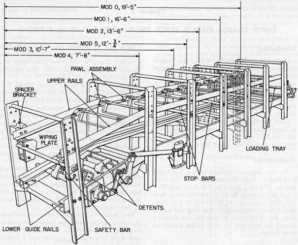
Figure 1.-Depth Charge Release Track Mk 9 Mods 0, 1, 2, 3, 4, and 5.
|
|
into a new position, the pawl is free to rotate upward, permitting it to lift as the depth charge passes under it. There is a pawl for each depth charge except the forwardmost one, which is secured against forward motion by a stop bar.
Stop and Safety Bars. The stop bar, mounted between the forward pair of stanchions, is installed for a port track, shown in figure 4B. It consists of an iron rod passing through both stanchions with a collar welded about its inboard end. The collar acts as a stop against the inboard stanchion to prevent the rod from pulling through. Just inside the inboard stanchion the rod has a hole drilled through it. A toggle pin, when inserted through this hole, secures the rod in place.
|
|
The toggle pin is secured against loss by a chain attached to the side of the stanchion. Removal of the toggle pin permits the entire stop bar to be withdrawn from the inboard side of the track.
Bars of other design may be found installed at the forward end of some tracks. The bars are sometimes threaded at each end and secured in place by nuts, one welded to the bar and the other removable. Another type has either a nut or collar welded to one end and a built in spring loaded toggle at the other end.
Similar bars are provided for installation between each pair of stanchions of the track. These are used when ready condition of the track is not desired, and provide further protection against
|
5
|
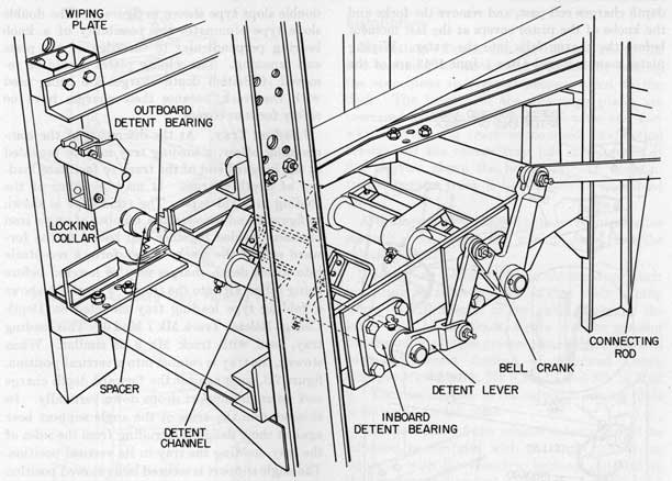
Figure 2.-Release Trap of Track Mk 9.
|
|
heavy weather. Because these bars do not require rapid removal, they are usually of the type secured with nuts.
For safe stowage, when ready condition is not required, a safety bar may be mounted between the
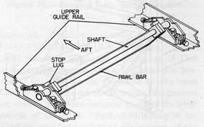
Figure 3.-Pawl Assembly of Track Mk 9.
|
|
aftermost pair of stanchions, figure 4A, to prevent the loss of a depth charge from the release trap. This bar is the same as the forward stop bar just described, with its collar and toggle pin mounted at the inboard side of the track. Another type of safety bar, the "Boston" type, may be installed. This bar is shown in figure 5, installed in a starboard track. It is designed for rapid removal by rotating the handle 90°, lifting the bar out of the slot in the inboard mounting plate and drawing it free of the outboard mounting plate. NavOrd OCL M16-44 contains instructions and plans for the construction and installation of various types of stop and safety bars.
Wiping Plates. A wiping plate, figure 1, is installed on each of the aftermost stanchions. They are designed to catch the knobs of both the safety forks and pistol covers when used as the
|
6
|
|
depth charges roll past, and remove the forks and the knobs of the pistol covers at the last moment before the charge falls into the water. Wiping plates manufactured after 1 June 1943 are of the
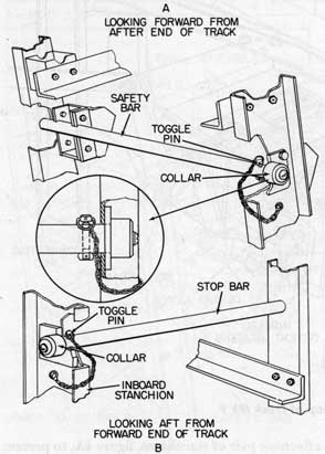
Figure 4.-Safety and Stop Bars.
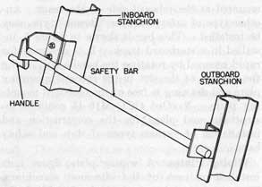
Figure 5.-"Boston" Type Safety Bar.
|
|
double slope type shown in figure 1. The double slope type eliminates the possibility of a knob bearing perpendicular to the edge of the plate and jamming. The wiping plates should be removed if British depth charges are being used with the track, because these charges have no safety forks or covers.
Loading Tray. At the discretion of the commanding officer, a loading tray may be mounted at the forward end of the track to facilitate loading of depth charges. It may be either of the folding or rigid type. The rigid type is shown in figure 6 and consists of a number of angle iron members welded together and bolted to the forward end of the track. They form a receptacle into which depth charges may be lowered before being rolled aft into the track. Figure 7A shows a folding type loading tray mounted on Depth Charge Release Track Mk 7 Mod 0. This loading tray, used with track Mk 9, is similar. When stowed, the tray is rotated into a vertical position, figure 7B, snug against the forward depth charge and its angle support drops down vertically. In this position the arms of the angle support bear against short flanges protruding from the sides of the tray, holding the tray in its vertical position. The angle support is secured in its stowed position by toggle pins, passed through "U" shaped brackets attached to the stanchions. When a folding tray is installed, the forward stop bar may be
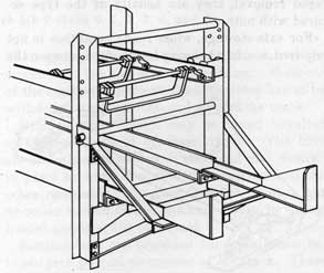
Figure 6.-Loading Tray, Rigid Type.
|
7
|
|
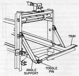
Figure 7a.-Loading Tray, Folding Type.
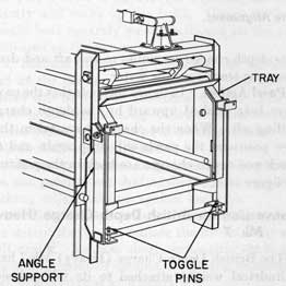
Figure 7b.-Loading Tray, Folded Position.
eliminated. Details for construction of each type of tray will be found in OCL M16-14.
Diol Shields. With the installation of Diol smoke generator equipment, a fire hazard is presented. Oil may become deposited on the cases of depth charges stored in the track. To prevent this, shields have been designed to cover the after portions of the track. Such shields may be installed by naval shipyards at the request of the commanding officer.
|
|
Installation
Mounting. Depth Charge Release Track Mk 9 is mounted in its desired position by bolting the stanchions to vertical plates welded to the deck. The lengths of the mounting plates are increased symmetrically from the after end forward. When the track is mounted, the section forward of the release trap lies at an angle of five degrees above the horizontal. In installation the entire track is handled as an assembled unit.
Alignment. Two alignments are required after mounting the track: the wiping plate, and the release detents.
The wiping plates must be shimmed, or their mounting surfaces ground, so that their wiping edges lie with respect to the guide flanges of the lower rails of the track, figure 8. The spacing for the outer plate is greater than for the inboard plate to prevent fouling of weighted Depth Charges Mk 8 Mod 0, Mk 9 Mod 4 and Mk 14 Mod 0. The modification of the outboard wiping plate is shown in Ordalt 2203.
The positions of the release detents should be adjusted to conform with the angles shown in figure 9, with the eccentric bushing installed in the long connecting rod. Then the track control unit should be mounted and joined to the long connecting rod in order to maintain these angles when in the secure position. The stops on the track control unit should be adjusted so that the long arm of the bell crank has the terminal positions shown. Details of the alignment of bearings and detents are shown on BuOrd Dwg 328300.
Operation
Figure 10 shows the sequence of operation in releasing a depth charge. In "A," the track control unit is in the secure position, the after detent bearing against the after depth charge and holding it in the release trap, and the pawls bearing against the forward circumferences of the depth charges.
In "B," the track control unit has been operated into the release position. The after detent has rotated forward and down, releasing the after depth charge to roll over it; and the forward de-tent has rotated upward to bear against the next
|
8
|
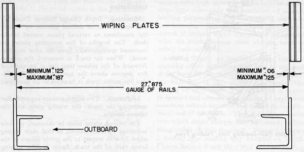
Figure 8.-Wiping Plate Alignment.
|
|
depth charge, preventing it from following the after one.
In "C," the track control unit has been operated back into the secure position. The forward detent has been rotated down and the after detent up again. This allows the next depth charge to roll over the forward detent into the release trap and stop against the after detent.
Wiping Plates. In the meantime the released depth charge has rolled on aft, passing the wiping plates. The safety fork and the knob of the pistol cover, if used, have been caught by the edge of the plates and drawn free, dropping to the deck.
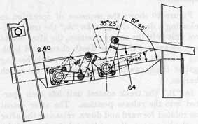
Figure 9.-Alignment Diagram for Release Detents.
|
|
The depth charge continues to roll aft and drops from the track into the water.
Pawl Action. In figure 10C note that the pawls have been pushed upward by the depth charges rolling aft. When the charges have taken their new positions, the pawls will drop again and the track and depth charges are back in the positions of figure 10A.
Conversion for British Depth Charge (Heavy) Mk 7
The British Depth Charge (Heavy) Mk 7 has a cylindrical weight attached to its inboard side. In order to accommodate this charge the guide rails of the track must be shifted outboard to permit the weight to clear the inboard stanchions. With this shift, the detents of the release track must also be repositioned. Figure 11 shows the release trap and lower rails as converted. Gauges manufactured in accordance with BuOrd Dwg 375574 for positioning guide rails are available at all shipyards and destroyer tenders. These gauges are designed and marked for positioning rails for both United States and British charges. To accomplish the conversion of the track for British charges proceed as follows.
|
9
|
|
Lower Rails and Release Trap, Starboard Track.
1. Remove connecting rod from bell crank of release trap and from track control lever.
2. Remove bell crank and detent lever from detent shafts and unbolt and remove detent shaft bearing brackets from lower inboard guide rails.
3. Remove locking collars and spacers from outboard ends of detent shafts and unbolt and remove outboard bearing brackets. Do not remove de-tents or detent shafts.
4. Clean detent shaft bearing surfaces with waste dipped in kerosene or carbon tetrachloride.
5. Unbolt the lower rails from all crosspieces and slide them outboard until their holes match the outboard set of holes in the crosspieces.
6. Rebolt them lightly by hand, allowing the rails to be adjusted when gauging.
7. Using the assembly gauge for British depth charges, BuOrd Dwg 375574, position the rails exactly and make up the bolts. Gauge surfaces should bear squarely on the rails and on the post indicated on the gauge.
8. Replace the locking collars on the outboard end of the detent shafts, leaving off the spacers which will be used on the inboard ends. The set screw hole in the locking collars is nearer one end of the collar, the face of the collar nearest the hole should be placed inboard.
9. Make up outboard and inboard bearing brackets, and push detent shafts inboard until outboard locking collars take up against bearings.
10. Place the spacers over the inboard ends of the detent shafts and replace the detent lever and bell crank. Replace short connecting shaft and check alignment of detents, levers and connecting rod, in accordance with figure 9.
11. Grease bearings in accordance with lubrication chart, figure 12, and apply preservative grease to exposed bearing surfaces.
Upper Rails, Starboard Track.
1. Remove pawls and pawl bracket assemblies from upper rails.
2. Remove upper outboard rail and spacer brackets from outboard stanchions.
3. Set brackets aside and bolt the rail directly against the outboard stanchions through the holes previously used for brackets, leaving the bolts set up only hand tight.
4. Position rail over lower guide rail using the
|
|
assembly gauge for British depth charges and tighten bolts.
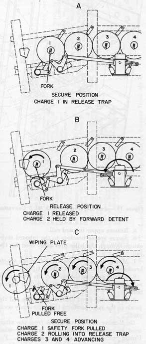
Figure 10.-Sequence of Operation, Depth Charge Release Track Mk 9.
|
10
|
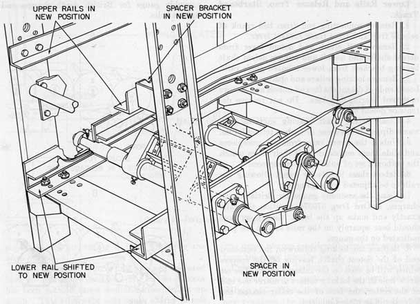
Figure 11.-Release Trap of Track Mk 9 Converted to Accommodate British Mk 7 (Heavy) Depth Charge.
|
|
5. Remove upper inboard rail.
6. Secure spacer brackets to the inboard stanchions through the holes previously used for the rail.
7. Mount the upper inboard rail on the spacer brackets and take up the bolts hand tight.
8. Finally position the rail over the lower guide rail using the assembly gauge, and then tighten bolts.
9. Replace the pawl bracket assemblies and the pawls in the same positions they previously occupied.
10. Remove the wiping plates from the after-most stanchions and store for later use when United States depth charges are employed. For making the conversion from a port to a starboard track, all operations are the same as above except that everything is to the opposite hand.
|
|
Conversion of Tracks to the Opposite Hand
All Depth Charge Release Tracks Mk 9 are shipped assembled for a specific location, either port or starboard. This is indicated by a stamp, P or S, after the serial number. If, however, it is desired to convert one for use on the opposite side of the ship, this may be done as follows:
1. Follow all steps detailed in the previous paragraphs for conversion to British Depth Charge Mk 7 ( heavy) , except for steps 7 and 9 for lower rails and release trap.
2. In step 7 both the spacers and locking collars must be replaced on the ends of the shafts opposite that from which they were removed.
3. In step 9 install detent lever, bell crank and connecting rod on the ends of the detent shafts opposite those from which they were removed.
|
11
|
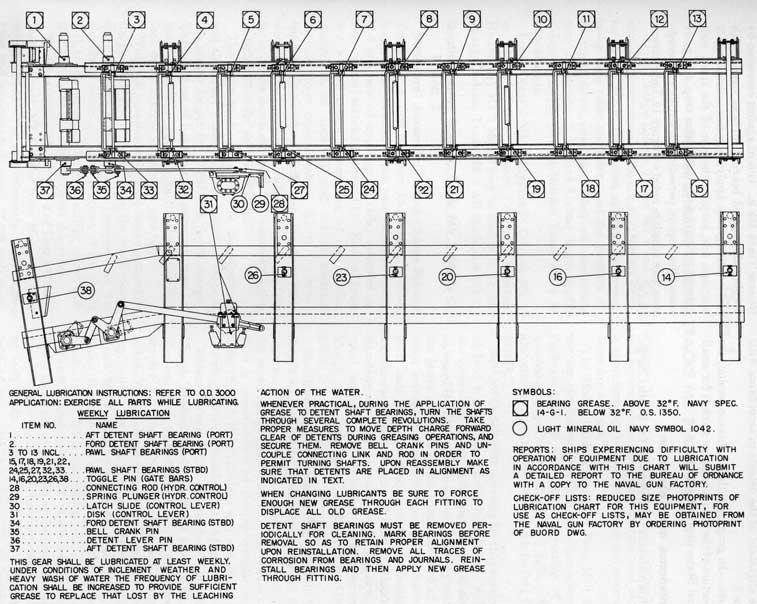
Figure 12.-Lubrication Chart, Depth Charge Release Track Mk 9.
225771 o-52-3
|
|
|
12
|
|
Make alignment of the detents in accordance with figure 9.
NOTE.-In gauging rails for this conversion, use the portion of the assembly gauge marked for small United States depth charges.
Maintenance and Lubrication
Little maintenance is required for Depth Charge
|
|
Release Track Mk 9. Guard against corrosion by keeping all exposed bearing surfaces coated with preservative grease, applying grease to detent shaft bearings, and keeping the rest of the track well painted. Bearings in the release trap and pawl assemblies require periodic lubrication in accordance with schedule noted on figure 12, Lubrication Chart.
|
13
|
Chapter 3
DEPTH CHARGE RELEASE TRACKS MK 3 AND MK 6
|
|
Depth Charge Release Tracks Mk 3 and Mk 6 were the forerunners of the Mk 9. They are similar to the Mk 9, their most apparent difference being their offset stanchions and the presence of an upper detent assembly. They will accommodate all current 17.625-inch United States depth charges. Depth Charge Release Track Mk 6 is now obsolete.
Local Control Mk 1, Hydraulic Control Mk 1 or Depth Charge Release Control (Electric-Hydraulic) Mk 3 Mod 0 may be used with Depth Charge Release Track Mk 3 All Mods and Mk 6.
Depth Charge Release Track Mk 3 Mods 0, 1 and 2
Structural Assembly. Depth Charge Release Track Mk 3 Mod 0, figure 13, consists of four longitudinal members (one pair of lower tracks and one pair of upper guide rails) mounted on four vertical stanchion assemblies. Each of these is a welded assembly consisting of two vertical stanchions, an upper tie rod and an inverted channel lower cross member. Above the lower tracks, each stanchion is offset one inch to provide clearance for the knobs of safety covers and safety forks on the depth charges. The assembly shown in figure 13 is for port installation.
The lower tracks are riveted to the stanchions and the upper guide rails are bolted in place at the proper height for 17.625-inch depth charges. The upper set of holes in each stanchion were for positioning the upper rails for the obsolete 24.825-inch depth charges and are not now used.
With the installation of Diol smoke generators the possibility of oil spraying on the depth charge cases presents a fire hazard. Designs exist for shields to cover the after portions of the tracks and, at the request of the commanding officer, such shields may be installed by naval shipyards.
Modifications. Mods 1 and 2 of Depth Charge Release Track Mk 3 differ from Mod 0 in their length. Mod 0 is approximately 159.5 inches long and accommodates eight 17.625-inch depth
|
|
charges; Mod 1 is approximately 135.5 inches long and accommodates seven such charges ; and Mod 2 is approximately 101.25 inches long and accommodates five charges.
The Mod 1 track is converted from Mod 0 by moving the forward vertical stanchion assembly approximately 20 inches aft and cutting off the overhanging portion of track and rails. This alteration is made in accordance with BuOrd Dwg 424659.
NavOrd Ordalt 2833 provides for the conversion of Mod 1 track into Mod 2 reducing its weight and providing weight and moment compensation on board DMS's. This is accomplished by cutting the guide rails and tracks 1 inch forward of the third stanchion from aft, leaving the assembly with only three vertical stanchion assemblies. The forward stop bar, removed from the discarded stanchion assembly, is reinstalled in the new forward assembly. Instructions for converting a Mod 0 track into Mod 2 are covered by Ordalt 3094.
Modification for Accessibility. Ordalt 2238 details instructions for modifying the second from aft stanchions in order to increase accessibility to the depth charge just forward of the release trap. This is accomplished by cutting circular access holes through the stanchions and restoring them to strength with a doubler plate, figure 13.
Release Trap. The release trap for Depth Charge Release Track Mk 3 All Mods is nearly identical with that of Track Mk 9, described in chapter 2. Since Track Mk 3 is not designed to take British depth charges, the spacer and locking collar, installed over each detent shaft in Track Mk 9 release trap, is not required. The detent shafts do not extend beyond the outboard track as in the Mk 9 installation.
Pawls. Eight pairs of pawls are mounted, figure 13, on the upper rails of the track assembly, spaced to bear against the forward circumference of each depth charge. Each pair of pawls is bridged by a pawl bar, figure 14, to provide a
|
14
|
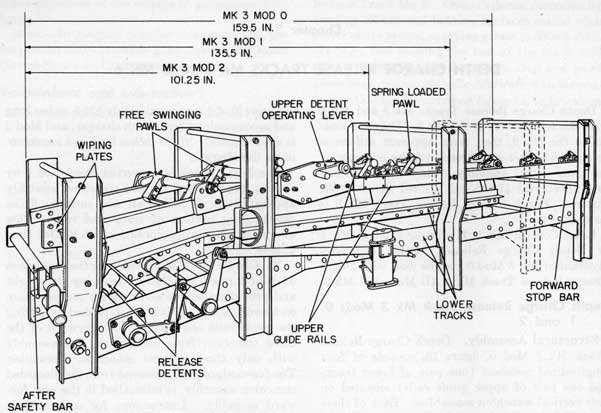
Figure 13.-Depth Charge Release Track Mk 3 Mods 0, 1 and 2.
|
|
surface against which the streamlined case of Depth Charge Mk 9 can bear. The after two pairs of pawls are free swinging clockwise, but are held in their proper downward sloping position by lugs bearing against the top surface of the upper rails.
The pair of pawls third from aft is part of an upper pawl and detent assembly, figure 14, in which the pawl bar bears against the forward surface of the third depth charge from aft and the detent against the after surface of the fourth charge from aft. This arrangement relieves the release detents of the weight of the forward five depth charges. A crank is installed on the inboard end of this pawl and detent shaft which, when operated, rotates the detent clear of the charge and permits all five forward charges to roll aft into new positions. The crank can be locked in either its secure or release positions by a spring loaded pin mounted in the crank handle,
|
|
14 and is limited in rotation by stop bolts passing through the bearing plate.
The five forward pairs of pawls are spring loaded to hold them in their proper downward sloping position. They require positive pressure against them to make them lift when rolling a depth charge aft.
Stop and Safety Bars. To prevent depth charges from rolling out of the track in rough weather, there is a stop bar mounted at the forward end of the track, figure 15. This is a steel rod passed through the forward pair of stanchions with a nut welded to its inboard end. A toggle pin, passed through the rod just outboard of the inboard stanchion, secures it in place. The toggle pin is secured against loss by a chain attached to the stanchion.
A vertical arrangement of stop bars also may be found installed with this track. This consists of two bars mounted vertically across the mouth
|
15
|
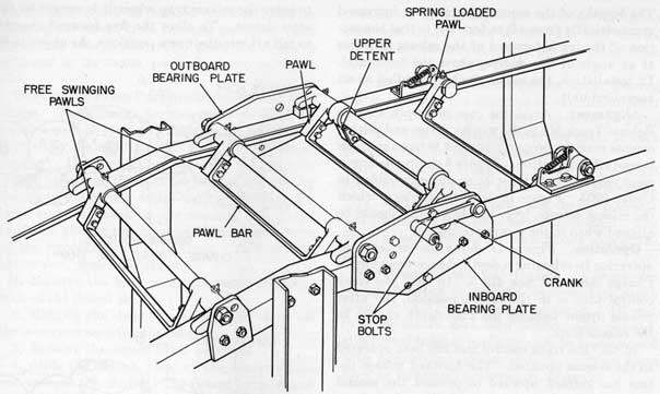
Figure 14.-Pawl Assembly of Track Mk 3.
|
|
of the track and passing through brackets specially mounted there. Details of this type of bar and of others authorized for installation will be found in NavOrd OCL M16-44.
A safety bar of the "Boston" type, figures 5 and 13, has been authorized by NavOrd OCL M4-44 for installation at the after end of the track to
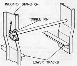
Figure 15.-Stop Bar for Track Mk 3.
|
|
prevent accidental discharge of a depth charge from the release trap.
Wiping Plates. Wiping plates, similar to those described for Depth Charge Release Track Mk 9, are also installed on the after stanchions of Depth Charge Release Track Mk 3. These are for the purpose of removing safety forks and the knobs of pistol covers when depth charges are released. If replacement of wiping plates is ever required, they must be replaced with those of the double slope type, figure 1, as safety forks may jam in the single slope type.
Loading Tray. The installation of a loading tray at the forward end of these tracks is authorized at the request of commanding officers and where Navy Yard availability permits. Either fixed or folding trays may be installed, depending upon the circumstances of the track installation. Details of construction of authorized trays will be found in NavOrd OCL M16-44.
Mounting. Depth Charge Release Track Mk 3 is mounted in its desired position by bolting the stanchions to vertical plates welded to the deck.
|
16
|
|
The lengths of the mounting plates are increased symmetrically from aft to forward so that the section of the track forward of the release trap lies at an angle of five degrees above the horizontal. In installation, the entire track is handled as an assembled unit.
Alignment. As in the case of Depth Charge Release Track Mk 9, the wiping plates and release detents must be properly aligned before the track is ready for operation. Figure 8 shows the alignment requirements for wiping plates, specified in Ordalt 2203. Figure 16 shows the angles to which the release detents, lever and bell crank should be aligned when in the secure position.
Operation. Figure 17 shows the sequence of operation in releasing a depth charge from Depth Charge Release Track Mk 3. In "A," the track control unit is in the secure position, the after release detent holding the rear depth charge in the release trap.
In "B," the track control unit has been operated to the release position. The forward release de-tent has rotated upward to prevent the second from rear depth charge from fouling the release trap ; the after detent has rotated down, clearing the after depth charge and allowing it to roll out of the trap. The upper detent is holding the five forward charges and preventing them from rolling aft.
In "C," the released depth charge has passed the wiping plates and the safety fork and knob of the pistol cover have been drawn free of the charge. The track control unit has been operated back to its secure position, the forward detent releasing the next depth charge and allowing it
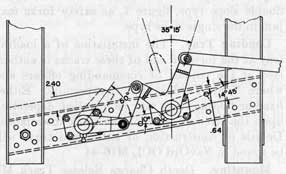
Figure 16.-Alignment Diagram for Release Detents, Track Mk 3.
|
|
to enter the release trap where it is caught by the after detent. To allow the five forward charges to roll aft into their new positions, the upper pawl
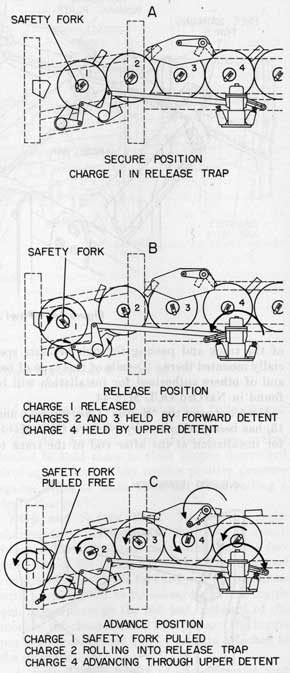
Figure 17.-Sequence of Operation, Depth Charge Release Track Mk 3.
|
17
|
|
and detent crank is rotated counterclockwise, clearing the detent from between the upper rails. After one charge has rolled past, the crank is returned to its secure position, shown in figure 17A.
Conversion From Port to Starboard and Vice Versa. These tracks are shipped assembled for either a port or starboard installation, and are so marked by the addition of P or S after the serial number. However, either assembly may be converted for use on the opposite side of the ship by reversing the release detent shafts, mounting the lever and bell crank on the opposite side of the track and placing the upper pawl and detent crank on the opposite side of the track. To make the conversion, proceed as follows:
1. Remove the lever and bell crank from the ends of the detent shafts.
2. Remove the detent brackets, then slack off the setscrews securing the detents.
3. Remove the detent shaft bearings.
4. Slide the detents clear of the detent shafts and remove the shafts. The detent keys should not be mislaid.
5. Turn both detent shafts end for end, reinstall detents, then reassemble shafts and shaft bearings.
6. Remount the detent brackets.
7. Replace the lever, bell crank and connecting shafts on the opposite side of the track from which they were removed, making sure they are aligned in accordance with figure 16.
|
|
8. Drive out the taper pin securing the upper pawl and detent crank to its shaft, and remove the crank. Remove the taper pin and collar from the opposite end of the shaft.
9. Remove and interchange the upper bearing plates in which the upper pawl and detent shaft is supported. Do not disturb the shaft in doing this but slide the bearings over the shaft as each plate is removed and reinstalled.
10. Mount the crank and collar on the shaft end opposite that from which they were removed.
11. Both the upper pawl and detent assembly and the release trap have been reassembled. The track is ready for use on the opposite side of the ship.
Maintenance and Lubrication. A minimum of maintenance is required to keep this depth charge release track in good condition. All rust spots should be kept wire brushed and painted, all exposed bearing surfaces must be kept covered with preservative grease and all working parts must be lubricated periodically, figure 18.
Depth Charge Release Track Mk 6 Mod 0
Depth Charge Release Track Mk 6 Mod 0, figure 19, is similar to Track Mk 3, just described, in every respect except that the upper pawl and detent assembly is eliminated and the track is only 101 inches long, accommodating only five standard depth charges. This track is now obsolete.
|
18
|
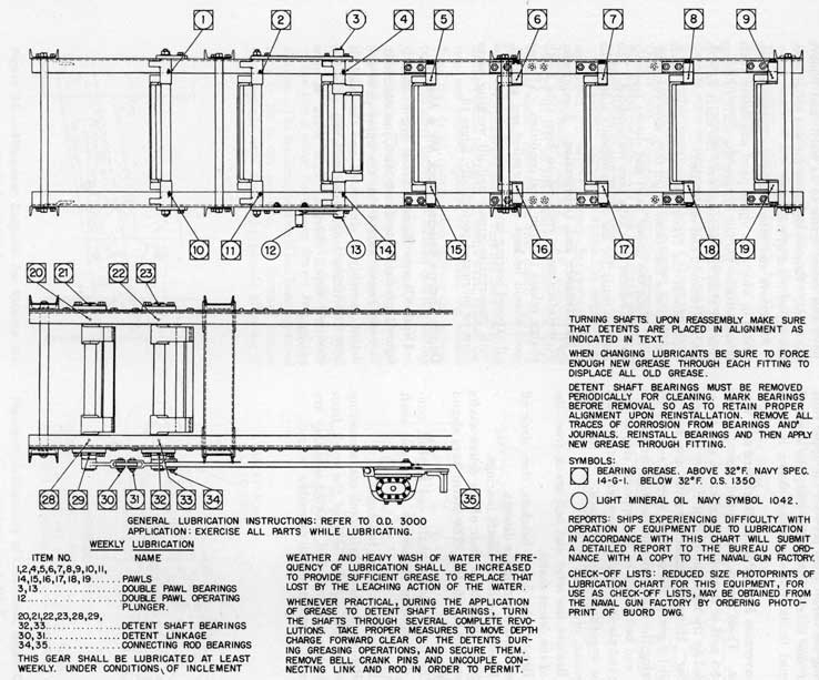
Figure 18.-Lubrication Chart, Depth Charge Release Track Mk 3.
|
19
|
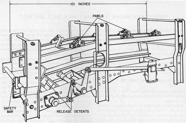
Figure 19.-Depth Charge Release Track Mk 6 Mod 0.
225TT1 O-52-4
|
20
|
Chapter 4
DEPTH CHARGE RELEASE TRACKS MK 1, MK 4, MK 5, AND MK 7
|
|
Depth Charge Release Tracks Mks 1, 4, 5, and 7 are grouped in this chapter because they all have similar release traps. These tracks accommodate only 17.625-inch United States Depth Charges Mks 6, 8, 9, and 14. Tracks Mks 1, 4, and 5 may have either Local Control Mk 1 or Hydraulic Control Mk 1 installed with them, but Track Mk 7 has its own built in local control mounted as part of the track. Depth Charge Release Track Mk 4 is now obsolete.
Depth Charge Release Track Mk 1 Mods 0 and 1
Depth Charge Release Track Mk 1 Mod 0 accommodates eight depth charges and Mod 1 holds five charges.
Structural Assembly. Depth Charge Release Track Mk 1 Mod 0, figure 20, consists basically of four longitudinal angles joined by vertical stanchions, upper crossbars and T-shaped lower cross-members. At the after end of the assembly the upper guide rails slope downward at an angle of 20° and the two after stanchions slope aft at an angle of about 45°.
The lower longitudinals consist of a channel and angle iron assembly with a small angle riveted inside each to form a track on which the depth charges rest.
Modification for Accessibility. Ordalt 2139 shows a rearrangement of the stanchions just forward of the escapement in order to provide increased accessibility to the next to last depth charge. Figure 21 shows these stanchions, relocated at an angle, exposing the depth charge for adjustment of pistols and depth setting mechanisms.
Depth Charge Release Track Mk 1 Mod 1 is the same as Mod 0 except that the forward section has been cut off to reduce the length and capacity of the track. Track Mod 0 is 11 feet 6 inches in length while the Mod 1 is 7 feet 1 inch in length.
Escapement. At the after end of the track the depth charges are retained by an escapement mechanism. Figure 20 shows the essential parts
|
|
of the escapement. The operating lever for Track Mk 1 is keyed to the inboard end of the escapement shaft, and hangs down vertically. For Mk 1 tracks, manufactured before July 1921, the lever hangs downward but lies at an angle of 30 degrees forward of the vertical.
The escapement arms are accurate castings mounted on a shaft and joined at their after ends by a rod. In the secure position, the after end of the arms are rotated down behind the aftermost depth charge, bear against it, and hold it in the track. A short section of angle iron is bolted inboard of the forward end of each arm. When the escapement is rotated during release of the aftermost depth charge, these angles come to bear against the after pawl assembly, and prevent it from being lifted, preventing the next to last depth charge from rolling aft. The escapement arms and operating lever are secured to the escapement shaft by setscrews and locknuts. The shaft is mounted in bearings supported in the aftermost stanchions of the track.
Pawls. Two sets of free swinging pawls are mounted between the upper rails in the after section of the track, figure 20. These are held at an angle of about 30° from vertical by stops bearing against the top of the rails. The two pawls of each assembly are mounted on a shaft and joined at their end by a U-shaped pawl bar. The pawl bar was added by Ordalt 1291 in order to accommodate streamlined Depth Charge Mk 9.
In addition to the free swinging pawls a double pawl assembly is mounted between the upper rails just aft of the fourth pair of stanchions. The forward pair of pawls of this double assembly bears against the third from aft depth charge, preventing it from rolling aft. The after pair of pawls of the assembly slopes aft and bears against the forward circumference of the next to last charge.
A crank is attached to the inboard end of the double pawl shaft to permit rotation of the pawls clear of the depth charges, figure 22C, and allow
|
21
|
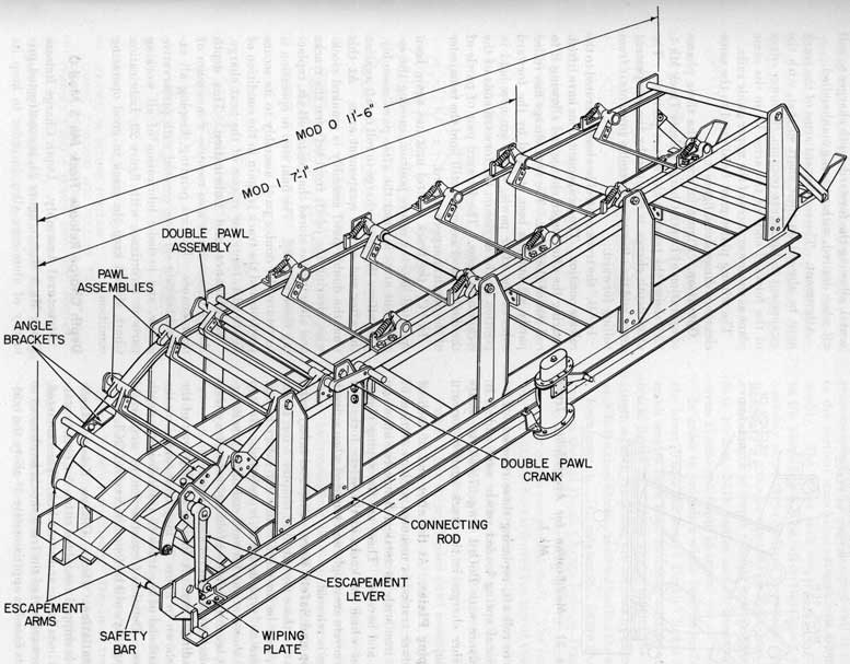
Figure 20.-Depth Charge Release Track Mk 1 Mods 0 and 1.
|
22
|
|
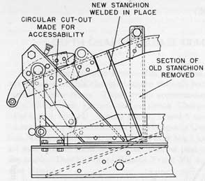
Figure 21. Modification for Accessibility, Track Mk 1.
them to roll aft, replacing those released. Five additional spring loaded pawls were added, in accordance with BuOrd Dwg 275053, to secure the other charges in the track against forward motion.
Wiping Plates. At the after end of each of the lower tracks, is mounted a short section of angle iron with its vertical flange cut off at an angle and beveled. These are the wiping plates, against which the knobs of the safety forks and pistol covers are caught and removed when a depth charge is released.
Stop and Safety Bars. Stop and safety bars, similar to those described in chapter 2 for Track Mk 9, may be installed. An after safety bar of the "Boston" type, figure 20, is preferred. No stop bar is shown at the forward end of the track, figure 20, because it shows a folding loading tray, thus eliminating the need for a stop bar.
Loading Tray. A folding loading tray of the type shown in figure 29 may be mounted on the forward end of the track to aid in loading depth charges. Details of construction of authorized loading trays will be found in NavOrd OCL M1644.
Installation. Depth Charge Release Track Mk 1 is shipped assembled either for port or starboard installation and so marked. When mounted, the forward end of the track should be elevated so that its base lies approximately 3° above the
|
|
horizontal, allowing the forward depth charges to roll aft when desired, without being manhandled.
Alignment. The escapement arms of the track must be aligned on their shaft so that, with the escapement in the secure position, the lower edges of the forward ends of the arms lie in the same plane as the lower faces of the upper guide rails.
The wiping plates must be aligned to the same clearance dimensions, figure 8.
Operation. Figure 22 shows the three phases of operation of Depth Charge Release Track Mk 1. "A" shows the track in the secure position. The after depth charge is retained by the escapement arms, and the after pawl assembly prevents it from rolling forward.
In "B," the track control has been operated to the release position. The escapement arms have lifted. clearing the after depth charge and allowing it to roll out of the track. The next charge has rolled partly aft but has been stopped by the forward sides of the after pawls, which are now held in position by the angles on the forward ends of the escapement arms. The forward pair of pawls of the double pawl assembly still hold the remainder of the depth charges forward.
In "C," the track control unit has again been operated into the secure position, causing the escapement arms to clear the after pawl assembly. This allows the depth charge to roll on aft against the after end of the escapement arms. At this time the double pawl assembly is cranked clockwise, clearing the pawls from between the tracks and allowing the stored charges to roll aft, replacing those released. The final step in operation is to return the double pawl assembly to its secure position and the track is again in the condition of figure 22A, ready for release of the next charge.
Maintenance and Lubrication. This depth charge release track also requires a minimum of maintenance. Routine painting, keeping all exposed bearing surfaces covered with preservative grease, and periodic lubrication of all working parts in accordance with figure 23, Lubrication Chart, should keep the track in good operating condition.
Depth Charge Release Track Mk 5 Mod 0
Structural Assembly. Depth Charge Release Track Mk 5 Mod 0, figure 24, is constructed primarily of aluminum alloy in order to keep its
|
23
|
|
weight to a minimum. Its escapement, pawls and their shafts are, however, of steel. The assembly consists of upper and lower tracks joined by vertical stanchions and by upper and lower cross-members. The lower rails are riveted to the lower
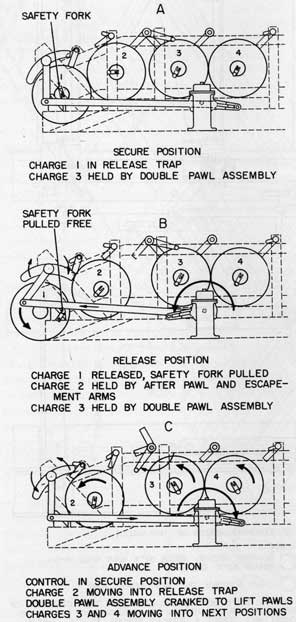
Figure 22.-Sequence of Operation, Depth Charge
Release Track Mk 1.
|
|
cross-members and a side gauging rail is riveted to the vertical stanchions on each side of the assembly. The upper rails are angles also riveted to the stanchions. The after stanchions of the assembly slope forward from their base and terminate with an angle cross bar between them. The overall length of Depth Charge Release Track Mk 5 is 10 feet, 10.75 inches and it accommodates seven 17.625-inch depth charges.
In order to provide a wider bearing surface on the lower tracks for use of Depth Charge Mk 9, small angles have been mounted outside of each track, figure 24. These angles extend the entire length of each track and are secured by bolts. At each bolt a steel block is inserted behind the angles.
Escapement. The escapement, figure 25, is the same as that of Depth Charge Release Track Mk 1, except that the operating lever is secured to the center of the escapement shaft. The connecting rod extends forward over the top of the track to the release control unit, which is mounted on the top of the track rather than to the side. A plate riveted across the top of the track serves as the mount for the track control unit.
Pawls. Six spring loaded pawl assemblies are bolted to the top rails of the track, figure 24. These bear against the forward circumference of the depth charges to prevent them from rolling forward in rough weather.
Stop and Safety Bars. The forward depth charge is secured against forward motion by a stop bar extending between the two forward stanchions. This bar is similar to that described in chapter 2 and shown in figure 4A. A safety bar at the after end of the track should be of the "Boston" type, installed as shown in figure 24.
Wiping Plates. The wiping plates for this track are short lengths of angle iron bolted to the after stanchions with their forward edges beveled to catch the knobs of safety forks and covers as they pass the stanchion.
Loading Tray. A loading tray of either the folding or rigid type may be mounted on the forward end of the track. Such trays are shown in figures 7 and 6 respectively. Details of trays for this track will be found in NavOrd OCL M16-44. If a folding tray is installed the forward stop bar is not required.
Installation. Depth Charge Release Track Mk 5 may be installed with no alteration either
|
24
|
|
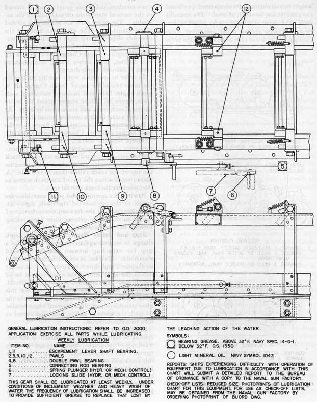
Figure 23.-Lubrication Chart, Depth Charge Release Track Mk 1.
|
25
|
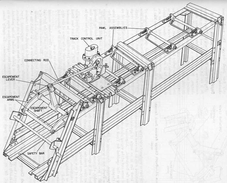
Figure 24.-Depth Charge Release Track Mk 5 Mod 0.
|
26
|
|
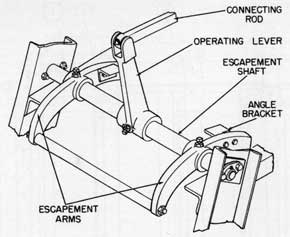
Figure 25.-Depth Charge Release Track Escapement.
on the port or starboard side of the ship. It should be mounted with its forward end elevated so that the track lies at an angle of approximately 6° above the horizontal. Alignment of the escapement arms and of the wiping plates should be the same as that specified for Track Mk 1 earlier in this chapter.
Operation. Operation of Depth Charge Release Track Mk 5 is essentially the same as that of Mk 1 previously described. The double pawl assembly, of course, is not present, and the track control unit is operated from the top of the track rather than from the side. The pawls function similarly, one bearing against the forward circumference of each depth charge. The forwardmost is an exception. This is retained either by a stop bar or folding loading tray, whichever may be installed.
Maintenance and Lubrication. As in the case of the Mk 1, this track requires a minimum of maintenance. Routine painting, application of preservative grease to exposed bearing surfaces, and proper periodic lubrication, figure 26, Lubrication Chart, will keep it in good operating condition.
Depth Charge Release Track Mk 4 Mod 0
Depth Charge Release Track Mk 4 Mod 0, figure 27, is exactly the same in all details as Track Mk 5 except for its length. This track has been
|
|
shortened at its forward end and accommodates only four depth charges. This track is now obsolete.
Depth Charge Release Track Mk 7 Mod 0
Depth Charge Release Track Mk 7 Mod 0, figure 28, is similar to the Mks 4 and 5, but is of steel construction and accommodates only two depth charges. It has, also, a built in manual release control unit, which is not interchangeable, with controls used with the other tracks. The illustration shows the arrangement of the release control and after safety bar for a port track. The track is installed with its forward end elevated so that rails lie at an angle of 6° above the horizontal. Its escapement and wiping plates are aligned in the same manner as for Tracks Mks 1, 4, and 5.
It has been found that the lower tracks of Depth Charge Release Track Mk 7 have become distorted by the continuous pressure of depth charges against them, particularly under rough weather conditions. In order to strengthen them, Ordalt 1898 provides for the installation of an additional angle beneath each track, figure 28.
The forward stop bar for this track is an elongated toggle pin, which extends between the forward stanchions. This is secured by the toggle which is upset against the outboard side of the forward outboard stanchion. A folding loading tray, shown in figure 29, may be installed on this track. In this event, the forward stop bar may be discarded.
A special adaptation of this track has been made for installation on DM's. Its feet have been fitted with special brackets permitting it to be mounted on top of the mine rails at the stern of the ship. These brackets permit the track to be demounted when the mine rails are in use.
Release Control Unit. The release control unit is mounted on a plate secured to the forward crossbar of the track. The control consists of a pedestal which mounts a crank shaft and handle. The crank handle carries a pin to which the escapement connecting rod is joined, so that rotation of the handle operates the escapement lever. Stops, in the form of bolts secured with locknuts, are mounted on plates attached to the pedestal. The connecting rod bears against these stops in its secure and release positions. To rigidly fasten
|
27
|
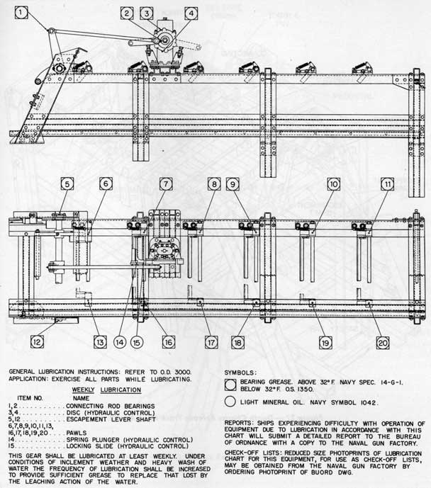
Figure 26.-Lubrication Chart, Depth Charge Release Track Mk 5.
225771 0-52-5
|
28
|
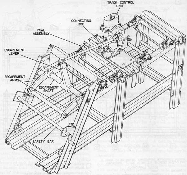
Figure 27.-Depth Charge Release Track Mk 4 Mod 0.
|
29
|
|
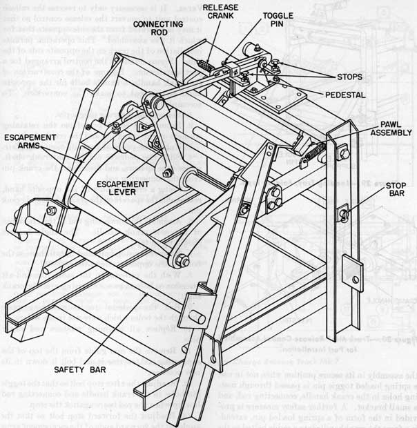
Figure 28.-Depth Charge Release Track Mk 7 Mod 0.
|
30
|
|
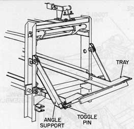
Figure 29.-Loading Tray, Folding Type.
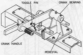
Figure 30.-Track Mk 7 Release Control Assembled
for Port Installation.
the assembly in its secure position when not in use, a spring loaded toggle pin is passed through mating holes in the crank handle, connecting rod, and a small bracket. A further safety measure is provided in the form of a spring loaded pin, extending from the crankhandle into a guide bolted to the top of the connecting rod. This prevents accidental operation of the crank when it is in its ready condition (toggle pin removed). A moderate outward pull on the handle withdraws the pin for operation.
Conversion from Port to Starboard or Vice
|
|
Versa. It is necessary only to reverse the release control unit to convert the release control so that it may be operated from the side opposite that for which it was assembled. This operation permits installation of the track on the opposite side of the ship. Figure 30 shows the control arranged for a port installation. Because of the construction of the crank handle, a handle built for the opposite hand is required to make the conversion. To accomplish this:
1. Remove the securing toggle pin.
2. Remove the cotter pins from the retaining washers on the crank pin and the crank shaft.
3. Unbolt the pedestal from its mounting plate.
4. Slide the pedestal out of the crank shaft, remove the spacers, and disconnect the crank pin from the connecting rod.
5. Using a crank handle of the opposite hand, reassemble the spacers on the crank shaft and crank pin.
6. Assemble the connecting rod to the crank pin of the new crank handle. The angle bracket should be on top.
7. Remove the stop bolts and install them in the holes on the opposite side of the pedestal.
8. With the pedestal in the same fore-and-aft direction as before, pass its bearing over the crank shaft.
9. Bolt the pedestal to its mounting plate through the holes which were not in use before.
10. Replace all retaining washers and cotter pins.
11. Remove the cam guide from the top of the connecting rod, reverse it and bolt it down in its new position.
12. Readjust the after stop bolt so that the toggle pin holes in the crank handle and connecting rod line up when the rod bears against the stop.
13. Readjust the forward stop bolt so that the angles at the forward ends of the escapement arms hold the after pawls down when the control is in its release position.
Maintenance and Lubrication. The same minimum of maintenance is required for this track as for Mks 1, 4, and 5. It is lubricated in accordance with figure 31.
|
31
|
|
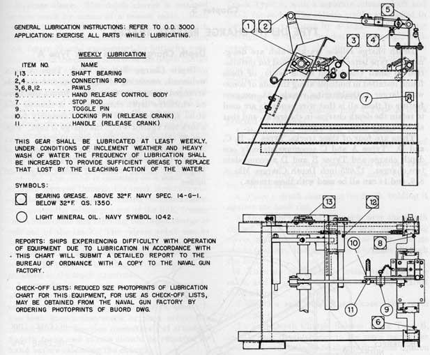
Figure 31.-Lubrication Chart, Depth Charge Release Track Mk 7.
|
|
|