|
Folks,
Depth Charge Projector Mark 1, OP 63, 1918, covers the "Y" gun depth charge projector.
Please report any problems with the Mail Feedback Form for correction.
Richard Pekelney
Webmaster
|
|
|
|
1
|
|
TABLE OF CONTENTS.
|
Page. |
| 1. Introduction |
3 |
| 2. General description |
4 |
| 3. Care and operation |
5 |
| 4. Tactical use |
7 |
| 5. Allowances, etc |
8 |
| 6. Appendix-List of drawings |
9 |
LIST OF ILLUSTRATIONS.
| Plate I. |
Projector and cartridge. |
| II. |
Projector assembled with arbors, but without depth charges. |
| III. |
General arrangement of breech plug. |
| IV. |
Firing mechanism-disassembled. |
| V. |
Arbors. |
| VI. |
Extracting cartridge. |
| VII. |
Projector fired with dummy depth charges. |
| VIII. |
Suggested tactical uses. |
81825-18
|
2
|
|
This page is blank.
|
3
|
|
DEPTH CHARGE PROJECTOR MARK I (OR Y-GUN).
1. INTRODUCTION.
In the campaign against submarines the depth charge has been found the most satisfactory weapon against a submarine after it is submerged. A destroyer or other vessel passing over the location of a submarine, whether known or estimated from its last appearance, may drop one or more depth charges in the endeavor to explode a charge within effective distance of the submarine.
Obviously the area which can be covered by a destroyer dropping depth charges is limited to the straight or curved line representing the course of the destroyer. If the destroyer can enlarge its effective area to either side, the possibility of damaging the submarine is largely increased.
To meet this need, the depth charge projector Mark I is supplied. This consists roughly of a Y-gun, which on firing by a single centrally located powder charge projects a depth charge to each beam of the ship. Thus, in addition to one or more depth charges dropped from the stern as the vessel is crossing the estimated location of the submarine, two depth charges may be thrown to the sides and thus enlarge the area. The projector embodies certain principles of the nonrecoil gun; it is readily seen that all horizontal forces of recoil are balanced and that on firing the resulting action upon the deck of the vessel is one of downward thrust only. With service charge this thrust will amount to a total of 10 tons. The projector may therefore be mounted upon a comparatively light vessel, and is or will be supplied to destroyers, submarine chasers, yachts, and other vessels engaged primarily as submarine offensives.
The following data are noted:
| (a) Weights: |
| Projector proper |
pounds |
1,250 |
| Arbors (each) |
do |
145 |
| Breechblock |
do |
49 |
| Cartridge case (loaded) |
do |
3 1/2 |
| Depth charge (loaded) |
do |
429 |
| Weight of charge and arbor as fired |
do |
565 |
| (b) Ballistic data: |
| Service powder charge |
pounds |
1 |
| Range |
yards |
50 |
Assuming that the effective radius against a submarine of a Mark II depth charge is 70 feet, the use of one depth charge dropped astern and one on either beam from the projector will give an effective danger area of 70 feet outboard of the one "wing" depth charge, 50 yards to the center depth charge, 50 yards to the other "wing" depth charge, 70 feet beyond that-in all a total of 440 feet, as compared with the effective diameter of 140 feet around the single central depth charge.
|
4
|
|
2. GENERAL DESCRIPTION.
PROJECTOR BODY.
The projector proper is of the highest grade close-grain gray cast iron. The two barrels form a 90° Y (P1. I), and are connected by a spherical powder chamber having an internal diameter of 13 inches. The barrels are 36 inches long, smoothbore, and of 6 inches internal diameter.
On the side of the powder chamber, at right angles to the plane of the barrel, is a cylindrical boss. This boss is bored out and finished to receive a 3-inch cartridge case, of the landing-gun type. The boss is threaded with external Acme threads with 3 serrations for engaging the breechblock, commonly known as the two-motion interrupted type. A circular base, 24 inches in diameter, with holes for securing the projector to the deck of the ship, is cast on, and integral with, the bottom of the powder chamber, approximately 9 inches from its center.
BREECHBLOCK AND FIRING MECHANISM.
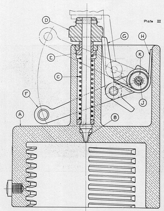
The breechblock is a bronze casting (Pls. III and IV) with a handle grip on either side. A boss on the center of the outer space is provided for mounting and housing the firing mechanism.
Threads are cut on the inside of the breechblock with serrations to match those on the projector boss.
The firing mechanism details are shown on Plate IV and the assembly on Plate III. The firing-pin spring C is not normally under firing compression, but is slightly compressed for returning and keeping the firing pin B in a housed position. The collar D secured to the firing pin, and the bushing E assembled in the housing, form the firing-pin bearings.
A lanyard is attached to the outer end of the firing lever F; and when the firing lever is pulled back, pivoting about the pin J, it carries the bell crank G to the position shown by the dotted lines. The bell crank G is pivoted off center, and the force exerted by the firing-pin spring keeps the end of the sear or bell crank G engaged under the collar D, thus preventing any premature release or accidental firing. When the firing lever and sear reaches the position shown by the dotted lines, the inner arm of the bell crank, or sear, strikes against the bearing of the firing-lever pivot and disengages the sear from under the collar D. The firing-pin spring has at the same time been fully compressed by drawing the firing pin to the rear, and now being released, the firing pin is thrown forward firing the primer and the collar D brings up against the main housing. Sufficient movement is allowed the bushing E to prevent interference with proper firing. After firing, the firing-pin spring C, acting against the bushing E, and the collar D, returns the firing pin to a housed position. The coil spring H bearing against the housing and the bell crank G serves the double purpose of returning the firing lever F to its original position and of engaging the sear or bell crank G under the collar D.
The firing mechanism can only be fired by a direct steady pull on the firing lever, and will not fire unless the lever is pulled back to the full limit of its throw; that is, the firing pin will always remain housed until the sear is released. The whole mechanism may easily be disassembled, the firing pin and spring being removed as a unit by unscrewing the cap over the bushing E.
|
5
|
|
ARBORS.
The firing mechanism of the United States depth charges is so arranged that firing the-depth charge in the line of the axis of the cylinder would injure its mechanism. It is, therefore, necessary to fire the depth charges at right angles to the cylindrical axis, and ammunition holders or arbors are provided for this purpose. The arbor (Pl. V) consists of a high grade cast-iron cylinder, machine finished to 6 inches outside diameter. This cylinder extends into the barrel of the projector 36 inches, or flush with the walls of the powder chamber. A cylindrical cradle or tray is cast as an integral part of the cylinder and at right angles to the main axis. This cradle conforms to the outside diameter of the depth charge. At one end of the cradle is a permanently secured clamp, which fits into the flange on one end of the depth charge, and on the other end of the cradle an adjustable clamp is provided which is set up by a hand clamp once the depth charge is in place.
AMMUNITION.
The cartridge case used is the 3-inch Navy landing gun case and is loaded with black sphero hexagonal powder similar to that used for torpedo ejection. The following powder charges give approximately the corresponding ranges:
One pound, 50-yard range (service charge).
One and one-quarter pounds, 66-yard range.
One and one-half pounds, 80-yard range.
|
When the projector is installed on shipboard a special davit is also installed in such a position that it can serve both barrels. The arbors are first placed in the barrel of the projector, then each charge is raised by the davit and secured to its arbor.
3. CARE AND OPERATION.
CARE.
The barrels should be kept clean and well oiled, and care should be taken that no water, oil, or other sediment is in the chamber before firing. Frequent inspection and lubrication of the breechblock and firing mechanism is necessary, particularly when exposed to severe weather conditions. When arbors and charges are not in place, muzzles should be closed by wooden plugs and protected by muzzle bags. These may be improvised on board ship. The arbors should be well slushed to prevent rusting. It may be found profitable to have canvas covers for the arbors to protect them from the weather, but these covers should be fastened so as to be easily taken off.
LOADING.
To load the propelling charge into the gun, considering the breechblock has been removed from the breech of the gun, a cartridge case is placed into the chamber of the gun and pushed in until the inner flange of the case is tight against the face of the breech boss.
To attach and secure the breechblock, the gunner takes a position directly in front of and facing the breech boss and chamber of the gun. The breechblock is picked up from the deck by the handles which are cast on either side of the block. Both of the gunner's hands are used-
|
6
|
|
one hand on each handle. The open end of the breechblock, which has three sections of threads cut on the inside of the block and which match three similar sections of threads on the breech boss of the gun, is the side of the block which should be turned facing the breech boss on the gun, and is also the side which is away from the gunner. Raise the breechblock until it is directly in front of the breech boss and in line with it. The breechblock should now be turned in such a position that the sections of threads on the inside of the block can enter the breech boss on the gun at three points where the threads have been cut away. In this position the left hand is depressed 30° from an imaginary horizontal line, and the right hand elevated the same amount above the horizontal line. The breechblock held in this position is pushed onto the breech boss as far as it will go. It will be noticed, also, in this position that the housing at the back of the breechblock which protects and holds the firing pin and trigger is inclined 60° toward the gunner's left arm. To lock the breech in place, which is to engage the threads in the breechblock with the threads on the boss on the gun, a right-hand motion or turn is given to the block through an arc of 60°. When the breechblock is locked, it will be noticed that the left-hand handle on the breechblock is elevated 30° above the horizontal and the right-hand handle depressed below the horizontal.
In placing the breechblock on the gun, extreme care should be taken that the block is put on right side up. The correct position of the block is shown on plate II. On projectors now in service, red marks for the entering and the firing positions of the block should be painted on the blocks, and one red mark should be placed on the center of the top of the breech of the gun so that no delay will be caused in adjusting the block in the proper position. In the case of future guns issued to service, the necessary marking will already be placed on the guns and these should not be painted over.
FIRING.
The firing mechanism in the breechblock does not require a separate operation to cock it before firing. The lanyard is hooked in the lever or trigger which extends from the firing-pin housing, and it will be found that this trigger hangs in a downward, vertical position when the breechblock is locked on the breech boss.
To fire the gun, the gunner stands directly in front of and facing the breech, but about 4 feet back from the breech. The lanyard is held without strain but by a firm grip, and at the command "Fire" a quick, steady pull is given.
This pull cocks or backs the firing pin out from the inner face of the breechblock, and in so doing depresses the helical compression spring which is placed around the stem of the firing pin. When the firing pin has reached its full firing position, a cam at the upper end of the firing trigger is raised, allowing the firing pin to jump forward again by the action of the spring, and causing the primer in the cartridge case to be struck.
For this reason, the lanyard must remain slack, without a strain being placed upon it, until the instant that the command to fire is given.
In case of a misfire, it is only necessary to slacken away on the lanyard, which allows the trigger to move back toward the breechblock by the action of the spring, and thereby engages the firing cam back of the firing pin. When this action has taken place, the firing of the piece is ready to be tried again.
|
7
|
|
After firing, the breechblock is unlocked (by turning it to the left) and withdrawn.
A hand extractor (P1. IV) is provided for use, if necessary. This extractor consists of a round bronze casting with a semicircular steel disk on the face, which fits over the flange of the cartridge case.
The wad from the mouth of the cartridge is not carried out of the barrels on firing, but remains in the powder chamber. After each three or four rounds the accumulated wads should be removed either by hand or by hooking out with a curved pointed rod.
Experiments should be conducted in order to discover the quickest way for reloading the gun after the first charges have been fired. It is usually necessary to swab out the barrels of the guns after the first shot to remove the remains of the powder charge which is likely to cause the next arbor to stick in the barrel. It has been found advisable to keep the arbors fastened to the charges on the deckhouse and to load the arbors in the gun with the charges attached. If this is done, it will eliminate the difficulty encountered in fastening a charge to the cradle in a rough sea.
SAFETY PRECAUTIONS.
1. Do not fire projector with one barrel loaded only.
2. See that safety clips are off depth charges before firing.
3. When not in danger zone keep firing gear set at safety on depth charge and safety fork on extender end.
4. In a heavy seaway, except when in submarine infested waters, keep sea lashings on the loaded projector.
4. TACTICAL USE.
No definite tactical rules can readily be laid down by the bureau for the use of this apparatus, as it is appreciated that vessels experienced in the depth-charge offensive are better qualified to develop the combined tactics of dropping and projecting depth charges. The following suggestions may, however, prove of value:
Referring to Plate VIII, two instances are shown. In the one, a straight line of three depth charges composed of two fired and one dropped forms a danger area 140 feet wide by 540 feet long. In the second instance, four depth charges, two dropped in succession and two fired from the projector, form a danger area in the approximate shape of a diamond or square with 105-yard sides. While in the latter case the effective zone of each depth charge does not extend completely to that of the adjacent, it is believed, owing to the dimensions of the submarine, that the entire interior of the diamond is rendered unsafe.
The time from the moment of discharge of the projector until the depth charges strike the water is four seconds. Assuming a vessel is making 20 knots, if one depth charge is released simultaneously with the discharge of the projector, the result will be the three depth charges in line. If, however, the one depth charge is dropped four seconds before the projector is fired and one four seconds after the projector is fired, or eight seconds from the first one dropped, the diamond-shaped figure shown will be formed.
|
8
|
|
Speeds differing from 20 knots and modifications of the time interval will increase or diminish the fore and aft diagonal of the diamond according as the speed and time interval is increased or reduced.
The above intervals of four and eight seconds are supplied for information only, as it is recognized that it is impracticable under the conditions of attacking the submarine to obtain any very accurate timing of charges.
The Mark II depth charge has been thoroughly tested for countermining; experiments have shown that at a distance of 50 feet from an exploding depth charge another charge will not be countermined; consequently no danger or difficulty need be expected in the successive dropping or firing of depth charges from a vessel. Similarly, actual firing test with the loaded depth charges as fired from the projector have been carried out and no damage to the depth charge or danger from its premature explosion is to be feared.
In the above suggestions no mention has been made of refiring the projector. The best time of reloading to be expected is about three minutes and it is more or less probable that no second opportunity will present itself to fire the projector. No effort should be spared, however, to reload quickly and to be ready to fire again should the occasion be presented.
5. ALLOWANCES, ETC.
One depth charge projector will be issued to each vessel equipped with this type of weapon. Sixteen arbors and eight cartridges will complete the allowance. Until the supply of arbors is adequate it is possible the full 16 arbors may not be immediately available. The standard Mark II depth charge will fit this projector and no separate allowance of depth charges for the projector will be made. From the regular allowance of depth charges issued to the vessel such as may be needed for use with the projector will be taken. A reserve stock of arbors and cartridges will be kept at the base to permit the allowance being maintained complete. No spare parts, tools, or other accessories will be issued, with the exception of the hand extractor.
Cartridge cases should be retained and turned into ammunition depots as occasion offers.
Ordnance drawings descriptive of the projector are cited in the appendix. These drawings will not be supplied to vessels except upon request.
RALPH EARLE,
Rear Admiral, United States Navy,
Chief of Bureau.
NAVY DEPARTMENT,
Bureau of Ordnance, January, 1918.
|
9
|
|
APPENDIX.
DEPTH CHARGE PROJECTOR MARK I.
| Part. |
Drawing No. |
| Projector, general arrangement |
58484 |
| Firing mechanism, general arrangement |
58465 |
| Breech block |
58486 |
| Firing mechanism details |
58487 |
| Holder and hand case extractor details |
58468 |

|
|

PROJECTOR AND CARTRIDGE.
|
|
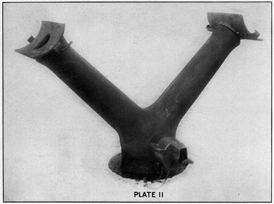
PROJECTOR ASSEMBLED WITH ARBORS, BUT WITHOUT DEPTH CHARGES.
|
|
GENERAL ARRANGEMENT OF BREECH PLUG.
|
|
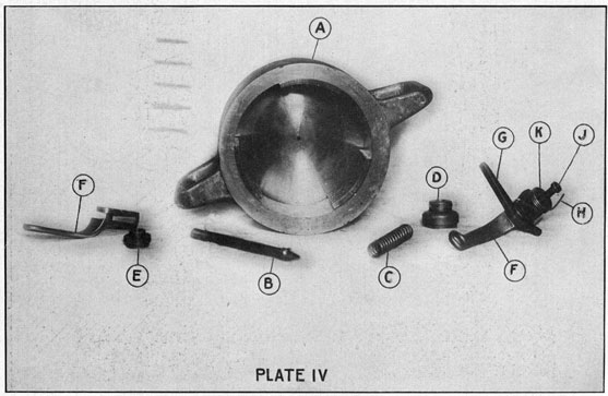
FIRING MECHANISM-DISASSEMBLED.
|
|
ARBORS.
|
|
EXTRACTING
|
|
PROJECTOR FIRED WITH DUMMY DEPTH CHARGES.
|
|
SUGGESTED TACTICAL USES.
|
|
|