|
|
DIVING
ENCLOSURE 7
|
1
|
|
DIVING
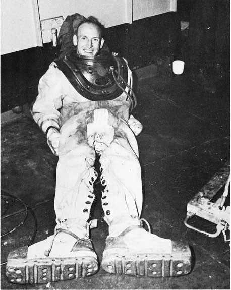
1. The possibilities of using divers to tunnel sand from underneath the ship's hull were considered on 18 January after the attempt to pull the MISSOURI clear the previous evening had failed. The facilities of the ASR type ship and the capabilities of the hydraulic jets in the hands of divers were first described by the commanding officer of the KITTIWAKE, ASR13, which had been assigned to the operation since the day before.
2. KITTIWAKE divers commenced making inspections along the side and bottom of the ship on 18 January, initiated a flow of information in regard to the type of sand encountered and commenced tunneling operations which were continued, as possible, until the MISSOURI was pulled clear. The CHANTICLEER, TRINGA, and PETREL, additional ASR ships, joined the operation later and their divers commenced operations in tunneling and inspections as the schedule and space alongside the ship permitted. All rescue vessels combined excavated about 1500 cubic yards of sand and gravel from under the MISSOURI.
3. The inspection reports and tunneling results are summarized in appendix A to this enclosure.
4. The diving and tunneling operations had to be coordinated closely with the dredging operations and were intended to accomplish, to some extent, the removal of the sand and gravel underneath the ship into the trenches being dredged alongside the MISSOURI by the COMBER and Washington. It was computed that the removal of 6400 cubic yards of sand from underneath MISSOURI'S hull could permit the ship to float on the tide expected on 2 February. Whereas only about one quarter of this amount of sand was actually tunneled away, the work of the divers in tunneling did loosen the sand under approximately one half of the bottom of the ship and is believed to have facilitated the effect of the bow twisting unit on 1 February in working the ship afloat. Throughout the diving and tunneling operations, the current along the sides of the ship made the work of the divers difficult. Divers were not allowed to work within 200 feet of a dredge suction which meant that, when dredging was being done along the side, diving and tunneling was curtailed or, when COMBER was passing along the side, stopped completely on that side. Furthermore, it became evident at the start of the operations, that there was little need for tunneling forward of frame 100 since all computations indicated that the MISSOURI bow would be afloat when the weight removal program had been completed. For this reason and because of the evident slowness of the tunneling process, the tunneling effort had to take second place to the placing of pontoons and beach gear on the quarters.
5. In addition to tunneling, divers performed the valuable function of inspecting the sides and under the bottom of MISSOURI. They inspected the rudders and propellers and reported them undamaged. They also provided valuable information as to the nature of the sand and gravel under MISSOURI and their reports and the samples of sand brought up contributed to the determination of the feasibility of the overall salvage plan. Divers located the breach in MISSOURI hull that opened three fuel tanks to the sea on the starboard side and their information was instrumental in the action that was taken to free these tanks of water.
6. The major function of the divers in the latter phase of the salvage operations was that of assisting with the rigging of pontoons. In the course of this operation, whenever pontoon cables or wire messengers were hung up, divers were sent below to attempt to clear them by tunneling or other means but the great pressure of the skegs in the after part of the ship on the sandy bed made these operations most difficult.
7. All dives were made under conditions of strong current and low visibility. Visibility was particularly bad because of dredging operations conducted in the area concurrently.
8. The following is a summary of the number of dives made by each of the ASR type ships employed.
| NAME |
DIVES |
AVERAGE DURATION |
| CHANTICLEER |
71 |
2 hours 12 minutes |
| KITTIWAKE |
94 |
1 hour 44 minutes |
| PETREL |
93 |
2 hours 10 minutes |
| TRINGA |
109 |
1 hour 12 minutes |
|
367 |
|
2
|
|
These dives were all normal except for three instances. KITTIWAKE and PETREL each had divers involved in cave-ins who had to be tunneled out by other divers. PETREL had one diver fouled with a round turn around the MISSOURI's starboard propeller shaft, which caused a little concern as the diver was behind the pontoons and difficult to reach.
APPENDIX (A) - Summary Of Tunneling Operations
|
3
|
|
SUMMARY OF TUNNELING OPERATIONS
|
182300 |
CO, KITTIWAKE reported as follows:
Between frames 122-144 diver can get under turn of bilge. Rolling chock is damaged (understood to have occurred in Naval Shipyard).
Propellers are two feet above ground.
Forward end of port rudder is in mud.After end in about 8 inches of mud.
Trench dug by COMBER at frame 165 is out 10 feet from vertical side of ship and is 9 to 11 feet deep, 45 degree slope.
Estimate can clear aft of frame 180 with tunneling hose.
|
|
190830 |
CO, KITTIWAKE reported results of inspection and tunneling as follows:
Starboard inboard and both port propellers inspected and clear of ground. Sand banked inside tunnel.
Mud cleared from around skegs.
Tunneling commenced at frame 142, 10 feet wide, 8 feet deep and 10 feet under turn of bilge.Tunneling rate 1 foot per hour.
|
|
192100 |
Obtained sand samples as follows - frame 65 - coarse gray sand. Frame 120 - small pebbles with some gray sand.Skeg area - coarse gray sand with few small pebbles.
|
|
200930 |
CO, KITTIWAKE reported that skegs had some clearance underneath, but that silt was collecting rapidly. Rudders had 3 feet clearance all around. There was a three foot ditch under rudders extending three feet astern.No evidence of mounds in rudder path.
|
|
201500 |
CO, CHANTICLEER reported results of inspection port side as follows:
Frame 120 - rolling chock is at diver's chest.
Frame 105 - rolling chock is belt high on diver - sand packed hard - slight trench at skin of ship.
Frame 100 - diver can reach six feet inside rolling chock.
Frame95 - diver can just reach rolling chock.
Frame75 - dredged trench exists 14-15 feet from ship.
Frame70 - diver can reach turn of bilge - not hard packed.
|
|
201530 |
CO, KITTIWAKE reported results of inspection as follows:
From frame 100 aft - scoured out.There is a 3 foot clearance under skeg. From frame 184 aft there is a minimum of 3 feet clearance under skeg. Trench is about 2 feet deep and 20 feet wide starting 20 feet from side.
|
|
221400 |
CO, CHANTICLEER reported results of inspection port side as follows:
Skeg fairly well clear aft of frame 191.
Mud and sand piled in tunnel.
Port rudder clear 2 1/2 feet aft, 1 1/2 feet forward.
Starboard rudder - same as port.
Frame 187 - 31/2 feet clear under skeg.
Frame 182 - skeg in soft mud.
Frame 179 - little clearance under skeg.
Frame 176 - skeg about 2 inches clear of bottom.
CO, KITTIWAKE reported results of inspection of starboard side as follows:
One man started at frame 160 and has worked back to frame 170 making a tunnel 7 feet high and 7 feet wide.
Frame 190 - skegs and rudder clear - depth 4 feet under skeg. There is a
mound between the propellers.
|
|
4
|
|
221500 |
CO, KITTIWAKE reported fine gray sand at frame 170 and mixed small pebbles and sand at rudder.
Tunneling operations as such were discontinued from this time until 31 January due to the pontoon work, the transfer of oil, stores, and ammunition, and dredging alongside. A thorough inspection of the bottom was made the afternoon of 31 January and KITTIWAKE and CHANTICLEER divers worked at tunneling on both sides amidships until 0500 1 February. In this last effort divers worked into 30 feet under the ship from about frame 100 to frame 140.
|
|
|
|
PONTOONS
ENCLOSURE 8
|
1
|
|
PONTOONS
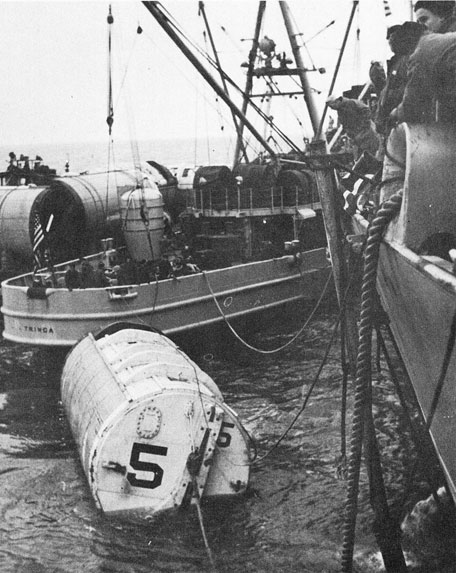
1. The suitability and feasibility of placing pontoons alongside MISSOURI were discussed on 19 January and Boston Naval Shipyard was requested to prepare the pontoons in store there for shipment on that date. The pontoons were ready for towing to Norfolk by 21 January and LUISENO was made available by ComServLant for towing the pontoon barges to Norfolk. The pontoons arrived in Norfolk on 24 January and were secured to a mooring previously prepared by KITTIWAKE. The pontoons were on two barges, one with four 80 ton pontoons, and the other with four 80 ton and two 60 ton pontoons. Each barge had been stowed by Boston Naval Shipyard with all of the gear required to rig these pontoons alongside MISSOURI except that extra fifteen fathom shots of pontoon chain had to be used due to the width of MISSOURI.
2. Placing pontoons alongside MISSOURI presented several problems new in the annals of pontoons. First there was a time factor that could accept no delay. In addition there was the problem of reeving pontoon chains under MISSOURI in positions where the maximum lift could be effected. It soon became evident that the hydraulic lance could not be used to pass a wire under the bottom as a messenger for the chain. This meant that a messenger wire had to be dragged under the ship from astern to the most forward chain position. As a matter of record this problem is described in detail in the following paragraphs.
3. CHANTICLEER and KITTIWAKE commenced passing a 7/16" wire under the stern on 22 January which was intended to reeve through and use as a messenger for the pontoon chains. This wire fouled on the starboard outboard propeller and all attempts to clear it from the topside failed until 25 January when PETREL came alongside the starboard quarter and put over a diver who cleared the wire on the propeller in about twenty minutes. This 7/16" wire was then used as a messenger to haul in a one and a quarter inch wire.
4. For the rigging of the wires and chains for the pontoons aft it was decided to use the PETREL and TRINGA as these vessels each had four (4) qualified diving officers, (CO and three (3) others each) while KITTIWAKE had only one, that being the CO, and the CHANTICLEER had two (2), CO and one other. Another factor was that the CHANTICLEER's capstans were of less capacity than the other ASR's and were not reversible. The ASR's began to saw the wire back and forth to get it forward to frame 171 where the first chain was scheduled to be placed for the #3 set of pontoons. Plans called for pontoon chains as follows, frames 171-175-179-183. The sawing of the messenger wire from frame 187 forward to frame 171 was a difficult task and required thirty-one (31) hours to accomplish. The rescue vessels worked quite a bit due to the action of the seas, which made it dangerous to use a wire smaller than 1 1/4". One main difficulty in getting this wire forward was due to the weight involved by placing 2000 tons of oil in the MISSOURI's stern in an attempt to crush the bed of sand that was under the ship.
5. During this difficult period of working wire under the after end of the ship, consideration was given to working a wire from the bow aft but the MISSOURI's tide gauges, two pipes installed amidships, prevented this. The method used to best advantage was the use of a 3/4" chain under the MISSOURI which was passed under the two rescue vessels, bringing the ends aboard the ASR's outboard rails and thence to the capstans. That gave a longer leg from the keel up, and reduced the friction that a short nip would give if the pull was exerted from the ASR's inboard rail. Another method tried was utilizing two YTB's to go ahead and back on MISSOURI's beam to saw this chain back and forth and attempt to work it forward. However, because the tide was strong, the YTB's could not be handled well and no success was achieved with this method. This method has merit and should prove successful in other instances. The problem of handling the tugs in the strong current was the major difficulty.
|
2
|
|
6. As soon as the 3/4" chain was worked up to frame 171 the reeving plate was rigged to run an extra wire through for the chain which was to be placed at frame 175.
This reeving plate has a capacity of three trailing wires but only two were sent through, using the outboard corners. However the ASR capstans could not drag this plate through and finally, after repeated efforts had been made, the following system was utilized which worked successfully, except in one instance when one wire fouled on the adjacent chain:
The eye of each wire was tagged with a metal tag, marked R or W corresponding to the red end or white end of the pontoon and, with the two wires being tended far apart, they passed under the ship successfully without taking a turn around each other.
7. One of the one inch trailing wires, (the forward one of the two) was then used to haul the 1 1/4" wire back through the hole under the keel so that a strong wire for pulling or reeving the chain under would be available. An attempt was made to reeve a 2 1/2" pontoon chain under the ship by placing a fairing cone on the 1 1/4" wire but the chain would not reeve under the ship. It was then decided to use the 3/4" chain again and connect a 15 fathom shot of 1 1/4" chain to it. The two chains were connected with connecting links instead of shackles so that there would be no shackle pin heads to foul on the keel or other obstacles. With each rescue vessel utilizing 3/4" chain to haul, the 1 1/4" chain was rendered back and forth under the MISSOURI in an attempt to make the channel larger and provide more room for the passage of the 2 1/2" pontoon chain. After several passes back and forth under the vessel the 3/4" chain was disconnected from one end of the 1 1/4", and the 2 1/2" pontoon chain was connected. The 2 1/2" chain connected with the 1 1/4" followed through without difficulty and in this manner all pontoon chains were run. After the second chain was run it was found that the wire for the third chain had taken a turn around this second chain at frame 175. To clear this wire, divers, one from the TRINGA and one from the PETREL, passed a 5/8" wire under the skegs astern and worked it forward as before.
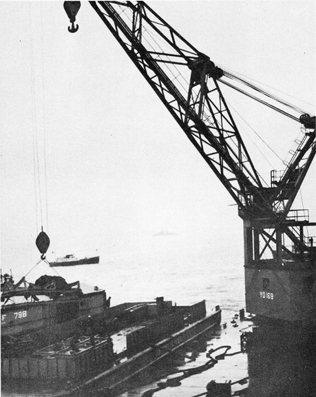
8. While the work of reeving wire to run the chain was going on, the pontoon barges were brought alongside TRINGA and PETREL as necessary to unload the shots of chain and other rigging gear. This gear was arranged on the ASR's in the order in which it was expected to be used. Pontoons were launched while the barges were alongside the ASR's in order that the distance to be towed could be kept to a minimum.
9. Before launching the pontoons from the barge, a preliminary test of all valves was made. The bonnets were removed from flooding valves and one 8 inch manila line was attached to each pontoon. This 8 inch manila line was used to tow the pontoon to the MISSOURI and also used as one of the lowering lines for the pontoon. As soon as the pontoon was launched from
|
3
|
|
the barge, it was towed to the MISSOURI and placed in position to pass the lifting chains through the hawsepipes on the pontoon. After this a second 8 inch manila line was secured to the pontoon, and both 8 inch lines were put on the MISSOURI. These lines were given sufficient space to keep the pontoon in position and were also used to control the sinking of the pontoon after the chains were rove through and secured.
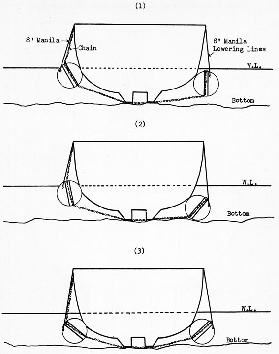
10. When the pontoons were placed in position abreast of the lifting chains, 3/4" wire straps were secured to the reeving straps on the pontoon and rove through the pontoon hawsepipes. One end of the 3/4" wire strap was secured to the lifting chain, the other to the hook on the lifting boom. This method was used to reeve the chain from the bottom of the pontoon hawse-pipe to the top of the pontoon. As soon as the chain was through the hawsepipe a toggle bar was put through the second link and secured. The chain was then lowered until the toggle bar took charge against the hawsepipe, supporting the weight of the chain. This procedure was followed on the first pontoon of each set until all chains were rove and pontoons ready to flood. While the chains were being rove through the pontoons, a detail of men secured the blow and vent hoses to the pontoons. At this time a second test of valves, etc., was made. When the chain was secured and all tests completed, the pontoon was flooded so that it was just afloat. The mate (or pontoon to be secured to the same chains) was then positioned on the opposite side of the MISSOURI, and the chains rove through the hawsepipes and all slack taken out of the chain. The chains were then secured to the side of the MISSOURI so when the mate pontoon sank it would slide down the chain to the bottom. Sketch 1 of appendix (A) shows position of pontoons and chain at this time of operation.
11. The mate pontoon (which had the chains rove through and secured to the MISSOURI) was then flooded and sunk to the bottom. A diver was then sent down on the pontoon to secure the toggle bar through the chain. When the bars were secured, the pontoon was given a blow. This was done to cinch the opposite pontoon down and under the MISSOURI so maximum lift could be obtained. Sketch 2 of appendix (A) shows position of pontoons at this point.
12. The pontoon which was blown, was then vented and allowed to sink, and all slack taken out of the chain again. Divers were again used to place the toggle bars in the chain (nearest link to the top of the sunken pontoon hawsepipe). When this was done both pontoons were blown and exerted about 70% of their maximum lift. Sketch 3 of appendix (A) shows position of pontoons at this point. This procedure was done to rig Nos. 2 and 3 sets of pontoons. Pontoon pairs were numbered 1, 2, 3 and 4 from aft forward.
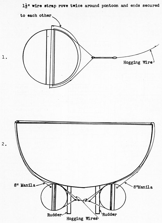
13. No. 1 set of pontoons presented a different problem due to the position of the pontoons in relation to the rudders and inboard propellers of the MISSOURI as well as to the contour of the MISSOURI's bottom in that location. Four sets of 1 1/4 inch wire hogging wires were placed under the ship, two sets forward of the rudders, and two sets aft of the rudders. Hogging wires were then cinched tight and secured to the main deck of the MISSOURI into steel plates that had been welded to the MISSOURI for that purpose. While these hogging wires were being secured in position, the pontoons were being prepared, as shown in appendix (B) Figure 1. This set of pontoons was then rigged with blow and vent hoses and tested, pulled into position alongside and hogging wires secured. Pontoons were then flooded and pulled into position shown in appendix (B) Figure 2.
14. No. 1 set of pontoons was the first set to be put in place but, due to the bend of the securing wire across the side coaming of MISSOURI, this securing wire parted on 30 January and this set of pontoons was not available for the coordination rehearsal. Strenuous efforts were made to get this set back in position before l February but the waves set up by destroyers that were used to test the agitation effects of high speed bow waves, upset the starboard pontoon. After this occurrence there was not sufficient time to reset these pontoons and neither was effective on 1 February. Both were secured alongside in a partially sunken condition in order that the wakes of the tugs would not greatly affect them.
15. The No. 4 set of pontoons was placed under the bow of the MISSOURI at frame 20 to 25. Instead of using chains for lifting, a 2 1/2 inch wire was used, otherwise the procedure was similar to that used for sets #2 and 3. Toggle bars were put through the eye on one end of the wires and the "flower pot" designed wedges were used on the other end of the wires. Not much difficulty was experienced in rigging this set of pontoons as there was room under the bow
|
4
|
|
at that point to pass the wire messengers. Eight inch manila lines were again used to control the sinking of these pontoons, the slack of the 2 1/2 inch wire was taken in with the anchor winches on the MISSOURI, and all excess wire was faked on the deck of the MISSOURI. Divers were sent down on the pontoon to check the wedges on the flower pot. The diver was then brought on board and the No. 4 set of pontoons blown. This set of pontoons exerted 100% of their lift.
16. The actual rigging and sinking of the pontoons after chains and wires were rigged did not present any more trouble than handling material of similar weights, etc. The greatest trouble was the interference of other salvage operation details. These details were necessary, however, and accepted. The solution of the problem of rigging pontoons under MISSOURI showed that there is no substitute for 2 1/2" wire or 2 1/2" chain for pontoons. The attempt to use 1 1/4" galvanized wire to hold the pontoons around the rudders was not good. This wire broke due to the working of the pontoons and circumstances were such that the pontoons could not be rigged again in time to be effective.
17. On the basis of this operation, the following recommendations for future operations of this nature are made:
|
a. More actual training, using pontoons, should be given to divers, and Diving Officers.
b. That pontoon valves be arranged on the pontoon to prevent kinks in all blow vent hoses and valves, etc.
c. That a better method of securing chocks under the pontoons while stored on the barge be devised so the chocks could be more readily removed. Considerable difficulty was encountered in casting the pontoons loose.
d. That the wire pennant secured to the 2 1/2 inch wire be shortened to 100 ft. with an eye splice on the end. When the present length of wire is on deck of the ship it becomes a hazard to personnel.
|
APPENDIX (A) - Pontoon Details (sets #2 and #3).
APPENDIX (B) - Pontoon Details (set #1).
APPENDIX (C) - Organization.
|
5
|
APPENDIX (A) TO ENCLOSURE 8
|
6
|
|
This page is blank.
|
7
|
APPENDIX (B) TO ENCLOSURE 8
|
8
|
|
This page is blank.
|
9
|
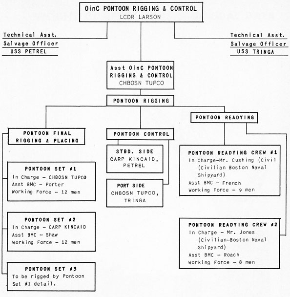
APPENDIX (C) TO ENCLOSURE 8
|
|
|
WEIGHT COMPUTATIONS AND TIDAL DATA
ENCLOSURE 9
|
1
|
|
WEIGHT COMPUTATIONS AND TIDAL DATA
I Weight Computations
1. The MISSOURI's drafts just prior to grounding, obtained from the external draft marks were:
| Forward |
= 35' - 09" |
| Aft |
= 36' - 09" |
The drafts just subsequent to grounding, obtained with lead lines were:
| Forward |
= 29' - 00" |
| Aft |
= 30' - 00" |
The weight removal required to allow the vessel to float free was 57,400 tons (displacement before grounding) - 45,500 tons (displacement after grounding) = 11,900 tons.
2. A rough set of calculations made during the evening of 17 January, revealed that the following weights could be readily removed from the ship to lighten her:
| Fuel and Diesel Oils |
7762 |
tons |
| Potable Water |
558 |
tons |
| Feed Water |
186 |
tons |
| Ammunition |
2193.4 |
tons |
| Boats |
30.4 |
tons |
| Anchors |
26.8 |
tons |
| Anchor Chain |
107 |
tons |
| Personnel |
107.1 |
tons |
| Dry Provisions |
250 |
tons |
| Fresh Provisions |
100 |
tons |
| TOTAL |
11,320.7 |
tons |
3. On 23 January, with all required data available, an accurate set of computations were made of the weights that could be removed to lighten the ship for any pull-off attempt. A summation of these weights is as follows:
| Fuel Oil |
7973.568 |
tons |
| Diesel Oil |
149.180 |
tons |
| Potable Water |
724.980 |
tons |
| Feed Water |
372.900 |
tons |
| Ammunition |
2204.817 |
tons |
| Boats |
34.020 |
tons |
| Boat Skids |
10.320 |
tons |
| Anchors |
27.490 |
tons |
| Anchor Chain |
112.830 |
tons |
| Dry Provisions |
199.070 |
tons |
| Fresh Provisions |
90.540 |
tons |
| Personnel |
102.000 |
tons |
| TOTAL |
12,001.715 |
tons |
The computations are included herein as appendix (A).
|
2
|
4. A summation of "Expected Weight Removals" and "Actual Weight Removals" as of 0600, 31 January, for the "Coordination Rehearsal" is as follows:
|
Expected
Weight
Removals |
Actual
Weight
Removals |
| Fuel Oil |
7973.568 |
8002.00 |
| Diesel Oil |
149.180 |
148.50 |
| Potable Water |
724.980 |
708.00 |
| Feed Water |
372.900 |
365.00 |
| Ammunition |
2204.817 |
2204.82 |
| Boats |
34.020 |
34.02 |
| Boat Skids |
10.320 |
10.32 |
| Dry Provisions |
199.070 |
203.17 |
| Fresh Provisions |
90.540 |
91.49 |
| TOTAL (TONS) |
11,759.395 |
11,767.32 |
These computations were made in the same manner as those in paragraph 3, outlined in detail in appendix (A).
5. A summation of "Expected Weight Removals" and "Actual Weight Removals" as of 0600, 1 February for the "Pull-Off" is as follows:
|
Expected
Weight
Removals |
Actual
Weight
Removals |
| Fuel Oil |
7973.568 |
8170.00 |
| Diesel Oil |
149.180 |
148.50 |
| Potable Water |
724.980 |
650.00 |
| Feed Water |
372.900 |
384.00 |
| Ammunition |
2204.817 |
2204.82 |
| Boats |
34.020 |
34.02 |
| Boat Skids |
10.320 |
10.32 |
| Dry Provisions |
199.070 |
205.18 |
| Fresh Provisions |
90.540 |
94.35 |
| Anchors |
27.490 |
27.49 |
| Anchor Chain |
94.780 |
94.78 |
| TOTAL (TONS) |
11,881.665 |
12,023.46 |
These computations were made in the same manner as those in paragraph 3, outlined in detail in appendix (A).
II Tidal Data
6. As stated in paragraph 1, the drafts just subsequent to grounding were obtained with lead lines, therefore, the accuracy of these readings was doubtful. It thus became necessary to establish accurate drafts just subsequent to grounding. This was done as follows:
|
a. Four tide gages of 6" extra strong steel tubing were fabricated by the Norfolk Naval Shipyard. They were driven into the ground alongside the ship at frames 1 S, 107 S, 107 P and 210 P. A damping device and scale for reading the depth of water were attached to each gage. Readings of the tide gages and the ship's external draft marks were taken at each high and low tide together with the exact time of the high or low tide.
b. The Coast and Geodetic Survey and the Public Works Department of the Norfolk Naval Base furnished a continuous record of height and time of tides at Sewall Point, which heights and time were converted to the actual location of the ship.
|
|
3
|
c. A correction of the data obtained in paragraphs 6a. and 6b. revealed that the drafts just subsequent to grounding were:
| Forward |
27.7' |
| Aft |
31.3' |
| Mean |
29.5' |
Therefore, the mean draft just subsequent to grounding obtained from the tidal data study of 29' 06" was exactly the same as the mean draft just subsequent to grounding obtained from the use of lead lines, as stated in paragraph 1. Therefore the ship was aground 11,900 tons.
|
7. A continuous plot of the predicted tide at the MISSOURI, the actual tide at the MISSOURI and the mean draft as weights were removed is included as appendix (A) to enclosure 10. The "Record of Weights Removed", included herein as appendix (B), was used together with the Displacement and other Curves to obtain the mean drafts for the plot.
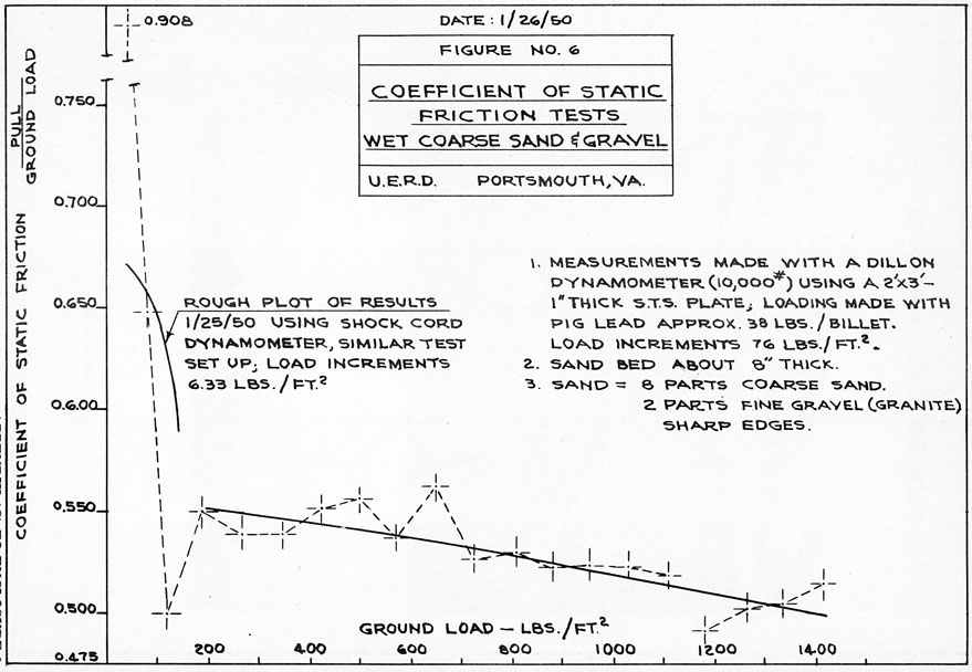
III Coefficient of Static Friction
8. In order to best determine the static coefficient of friction to be expected during pull-off, the Underwater Explosion Research Division of the Norfolk Naval Shipyard ran a series of tests. Samples of the bottom from around the ship were collected by divers and these samples were duplicated by the shipyard as closely as possible for the test performed. Results of the tests are included herein as appendix (C). A complete description of the tests can be found in the Underwater Explosion Research Division's Report UERD 2-50.
APPENDIX (A) - Weight Removal Computations.
APPENDIX (B) - Record of Weights Removed.
APPENDIX (C) - Coefficient of Static Friction Tests.
|
4
|
|
This page is blank.
|
5
|
|
Weight Removal Computations
1. Computations of the weights that could be removed to lighten the ship for any pull-off attempt are as follows:
a. Fuel Oil
| (1) |
Amount on board prior to grounding | 2,376,054 gals |
| (2) |
At 0600, 31 January 1950 (Coordination Rehearsal) or at any subsequent pull-off attempt the amount of burnable fuel to be retained plus the amount that could not be removed because of loss of suction |
98,079 gals |
|
|
2,376,000 gals |
|
|
98,079 gals |
| (3) |
Amount removed |
2,277,921 gals |
(4) Fuel Oil Data. The following data were obtained from Petroleum Laboratory N. S. C. Norfolk on the specific deliveries made to the MISSOURI:
Sp. Gr. .9415
7.841 lbs/gal
6.802 bbls/ton
42 gals/bbl
|
(5) Weight removed 2,277,921 / (6.802 x 42) = 7,973.568 tons
b. Diesel Oil
| (1) Amount on board prior to grounding | 51,000 gals |
| (2) At 0600, 31 January 1950 (Coordination Rehearsal) or at any subsequent pull-off attempt the amount of burnable diesel oil to be retained plus the amount that could not be removed because of loss of suction |
3,370 gals |
|
51,000 gals |
|
3,370 gals |
| (3) Amount removed |
47,630 gals |
(4) Diesel Oil Data. The following data were obtained from Petroleum Laboratory, N. S. C. Norfolk on the specific delivery made to the MISSOURI:
Sp. Gr. .8423
7.013 lbs/gal
7.065 bbls/ton
42 gals/bbl
|
(5) Weight removed 47,630 / (7.605 x 42) = 149.18 tons
|
6
|
c. Potable Water
| (1) Amount on board prior to grounding |
208,000 gals |
| (2) At 0600, 31 January 1950 (Coordination Rehearsal) or at any subsequent pull-off attempt the amount of usable water to be retained plus the amount that could not be removed because of loss of suction |
13,000 gals |
|
208,000 gals |
|
13,000 gals |
| (3) Amount removed |
195,000 gals |
(4) Water Data obtained from Petroleum Laboratory, N. S. C. Norfolk:
(5) Weight removed (195,000 x 8.328) / 2240 = 724.98 tons
d. Feed Water
| (1) Amount on board prior to grounding |
115,000 gals |
| (2) At 0600, 31 January 1950 (Coordination Rehearsal) or at any subsequent pull-off attempt the amount of usable water, plus the amount in the steaming boiler plus the amount that could not be removed because of loss of suction |
14,700 gals |
|
115,000 gals |
|
14,700 gals |
| (3) Amount removed |
100,300 gals |
(4) Water Data obtained from Petroleum Laboratory, N. S. C. Norfolk:
(5) Weight removed (100,300 x 8.328) / 2240 = 372.9 tons
e. Ammunition
| (1) Amount on board prior to grounding that could be removed by 0600, 31 January 1950 (Coordination Rehearsal) |
2,204.817 tons |
Note: Weight shown is based on information obtained from the ammunition invoices.
f. Boats
(1) The following small boats were on board prior to grounding and could be removed prior to 0600, 31 January 1950 (Coordination Rehearsal):
6 - 30' ML's
2 - 26' MWB's
1- 24' PPB (Mark IV)
1 - 28' PB
|
|
7
|
|
(2) All boats' complete outfit aboard and were fueled to capacity.
(3) Weight removed
| 6 - 30' ML's |
6 x 8443 - 50,658 lbs |
| 2 - 26' MWB's |
2 x 5251 - 10,502 lbs |
| 1- 24' PPB |
5750 - 5,750 lbs |
| 1- 28' PB |
9300 - 9,300 lbs |
|
- 76,210 lbs - 34.02 tons |
Note: Weights used obtained from Chapter 82 of BuShips Manual, except for 28' PB which was taken from name plate in the boat.
g. Boat Skids
(1) The following boat skids were on board prior to grounding and could be removed prior to 0600, 31 January 1950 (Coordination Rehearsal):
| 6 for 30' ML |
(Wheel mounted) |
| 2 for 28' ML |
(Wheel mounted) |
| 1 for 24' PPB |
(Nests in a 30' ML) |
(2) Weight removed:
Note: Weights were obtained from plans of skids.
h. Anchors
(1) The weight of the anchors on board at the time of grounding:
| Port |
30,620 lbs |
| Starboard |
30,960 lbs |
|
61,580 lbs - 27.49 tons |
i. Anchor Chain
(1) The following amounts of 3 3/8" Die Lock anchor chain were on board at the time of grounding:
| Port |
187.5 Fathoms |
| Starboard |
187.5 Fathoms |
| Total |
375.0 Fathoms |
(2) Anchor chain weight data obtained from the Design Section of the Norfolk Naval Shipyard:
(3) Weight of anchor chain (375 x 674) / 2240 = 112.83 tons
j. Dry Provisions
(1) Best possible estimate by MISSOURI Supply Department personnel of weight of dry provisions that could be off-loaded and consumed by 0600, 31 January 1950 (Coordination Rehearsal):
| Off Loaded |
390,476 lbs |
| Consumption |
55,440 lbs |
| Total removed |
445,916 lbs - 199.07 tons |
|
8
|
|
k. Fresh Provisions
(1) Best possible estimate by MISSOURI Supply Department personnel of weight of dry provisions that could be off-loaded and consumed by 0600, 31 January 1950 (Coordination Rehearsal):
| Off Loaded |
114,829 lbs |
| Consumption |
87,975 lbs |
| Total removed |
202,804 lbs - 90.54 tons |
1. Personnel
(1) By 0600, 31 January 1950 (Coordination Rehearsal) the following personnel and their effects could be removed: (ComCruLant decided that personnel would "stand by their ship" and not be removed, even temporarily, except as a last resort to lighten ship):
1000 crew
20 officers
Total - 1020
|
(2) Average weight of one man and his effects - 224 lbs.
(3) Weight removed (1020 x 224) / 2240 = 102 tons
m. Weight Removal Summary
| a. Fuel Oil |
7,973.568 |
| b. Diesel Oil |
149.18 |
| c. Potable Water |
724.98 |
| d. Feed Water |
372.9 |
| e. Ammunition |
2,204.817 |
| f. Boats |
34.02 |
| g. Boat Skids |
10.32 |
| h. Anchors |
27.49 |
| i. Anchor Chain |
112.83 |
| j. Dry Provisions |
199.07 |
| k. Fresh Provisions |
90.54 |
| l. Personnel |
102.00 |
| TOTAL - |
12,001.715 |
2. In paragraphs 1a, 1b, 1c and 1d the amounts of fluids that could not be removed because of the loss of suction on the storage tanks, and the amounts of usable fluids to be retained for the following 24 hours operations after any given pull off attempt were arrived at by consultation with the Chief Engineer and his assistants.
|
9
|
|
Record of Weights Removed
From 0845, 17 January 1950 to 0600, 1 February 1950
| 1. |
17 January |
|
TONS |
| a. |
0845 |
+ |
378.00 |
| b. |
0845-1315 |
- |
59.41 |
| c. |
1315-2000 |
- |
808.60 |
| d. |
2000-2300 |
- |
443.73 |
| e. |
2300-2400 |
- |
119.72 |
|
CUMULATIVE-TOTAL |
- |
1053.46 |
|
| 2. |
18 January |
| a. |
0000-2015 |
- |
2584.00 |
| b. |
2015-2400 |
- |
337.46 |
|
CUMULATIVE-TOTAL |
- |
3974.92 |
|
| 3. |
19 January |
| a. |
0000-0200 |
- |
179.00 |
| b. |
0200-1300 |
- |
1395.56 |
| c. |
1300-1345 |
- |
113.55 |
| d. |
1345-1430 |
- |
139.05 |
| e. |
1430-1445 |
- |
32.64 |
| f. |
1445-1700 |
- |
216.70 |
| g. |
1700-1800 |
- |
151.45 |
| h. |
1800-2045 |
- |
359.23 |
| i. |
2045-2400 |
- |
412.80 |
|
CUMULATIVE-TOTAL |
- |
6974.90 |
|
| 4. |
20 January |
| a. |
0000-0130 |
- |
187.07 |
| b. |
0130-0400 |
- |
416.40 |
| c. |
0400-0500 |
- |
48.93 |
| d. |
0500-0700 |
- |
13.83 |
| e. |
0700-1145 |
- |
84.90 |
| f. |
1145-1500 |
- |
22.50 |
| g. |
1500-1630 |
- |
33.00 |
| h. |
1630-2000 |
+ |
230.10 |
| i. |
2000-2400 |
+ |
51.10 |
|
CUMULATIVE-TOTAL |
- |
7500.33 |
|
| 5. |
21 January |
| a. |
0000-0600 |
- |
166.70 |
| b. |
0600-1200 |
- |
76.60 |
| c. |
1200-1745 |
- |
68.70 |
| d. |
1745-2000 |
+ |
183.24 |
| e. |
2000-2400 |
- |
51.10 |
|
CUMULATIVE-TOTAL |
- |
7680.19 |
|
|
| 6. |
22 January |
| a. |
0000-1100 |
- |
136.85 |
| b. |
1100-1300 |
- |
62.06 |
| c. |
1300-2400 |
- |
136.85 |
|
CUMULATIVE-TOTAL |
- |
8015.95 |
|
| 7. |
23 January |
| a. |
0000-1530 |
- |
121.70 |
| b. |
1530-1700 |
+ |
296.24 |
| c. |
1700-2400 |
- |
55.00 |
|
CUMULATIVE-TOTAL |
- |
7896.41 |
|
10
|
| 8. |
24 January |
| a. |
0000-1315 |
- |
163.00 |
| b. |
1315-1645 |
+ |
123.39 |
| c. |
1645-2330 |
+ |
251.40 |
| d. |
2330-2400 |
- |
6.15 |
|
CUMULATIVE-TOTAL |
- |
7690.77 |
|
| 9. |
25 January |
| a. |
0000-1045 |
- |
87.40 |
| b. |
1045-1300 |
+ |
1899.63 |
| c. |
1300-2400 |
- |
89.30 |
|
CUMULATIVE-TOTAL |
- |
5967.84 |
|
| 10. |
26 January |
| a. |
0000-1330 |
- |
150.20 |
| b. |
1330-1630 |
+ |
230.54 |
| c. |
1630-2400 |
- |
83.50 |
|
CUMULATIVE-TOTAL |
- |
5971.00 |
|
| 11. |
27 January |
| a. |
0000-1100 |
- |
114.60 |
| b. |
1100-1445 |
+ |
220.90 |
| c. |
1445-1530 |
- |
7.82 |
| d. |
1530-2400 |
- |
409.04 |
|
CUMULATIVE-TOTAL |
- |
6281.56 |
|
| 12. |
28 January |
| a. |
0000-1300 |
- |
641.00 |
| b. |
1300-1430 |
- |
271.00 |
| c. |
1430-1530 |
- |
49.30 |
| d. |
1530-1800 |
+ |
25.70 |
| e. |
1800-2400 |
- |
295.16 |
|
CUMULATIVE-TOTAL |
- |
7512.32 |
|
| 13. |
29 January |
| a. |
0000-0630 |
- |
304.64 |
| b. |
0630-0800 |
- |
13.90 |
| c. |
0800 |
- |
378.00 |
| d. |
0800-1245 |
- |
44.00 |
| e. |
1245-1430 |
+ |
56.95 |
| f. |
1430-1515 |
- |
1.15 |
| g. |
1515-1530 |
- |
24.02 |
| h. |
1530-1700 |
- |
206.92 |
| i. |
1700 |
- |
160.00 |
| j. |
1700-1900 |
- |
374.40 |
| k. |
1900-2400 |
- |
690.14 |
|
CUMULATIVE-TOTAL |
- |
9652.54 |
|
| 14. |
30 January |
| a. |
0000-0800 |
- |
1167.50 |
| b. |
0800-0930 |
- |
157.89 |
| c. |
0930-1100 |
- |
31.68 |
| d. |
1100-1200 |
- |
61.50 |
| e. |
1200-1500 |
- |
82.00 |
| f. |
1500-1630 |
- |
167.82 |
| g. |
1630-2400 |
- |
132.10 |
|
CUMULATIVE-TOTAL |
- |
11,453.03 |
|
11
|
| 15. |
31 January |
| a. |
0000-0500 |
- |
179.60 |
| b. |
0500 |
- |
160.00 |
| c. |
0500-0845 |
- |
22.85 |
| d. |
0845-1300 |
- |
223.45 |
| e. |
1300-1530 |
- |
199.20 |
| f. |
1530-1730 |
- |
77.91 |
| g. |
1730 |
+ |
160.00 |
| h. |
1730-1845 |
- |
14.65 |
| i. |
1845-1900 |
+ |
8.67 |
| j. |
1900-2030 |
- |
43.67 |
| k. |
2030-2130 |
+ |
31.88 |
| l. |
2130-2400 |
- |
15.30 |
|
CUMULATIVE-TOTAL |
- |
12,189.11 |
|
| 16. |
1 February |
| a. |
0000-0230 |
- |
79.61 |
| b. |
0230 |
- |
320.00 |
| c. |
0230-0500 |
- |
79.61 |
| d. |
0500-0600 |
- |
3.23 |
|
GRAND-TOTAL |
- |
12,671.56 |
|
12
|
|
This page is blank.
|
13
|
|
|