HYDRAULIC SYSTEMThe hydraulic system operates the ballast tank vents, steering, dive planes, torpedo tube shutter doors, the capstans and windlass, and raises the periscopes and SV radar mast. The oil pressures required to operate the hydraulic equipment are developed by electric motor-driven rotary pumps (IMO). Hydraulic motors, such as actuating cylinders, are the power units and use the power developed by the pumps and convert it to mechanical energy. Lines from the central power source radiate throughout the submarine and carry fluid under pressure to operate the various equipment. In order to perform these numerous tasks, a variety of valves, actuating cylinders, tanks, and manifolds are required. The actuation of the various hydraulically operated units aboard Pampanito often requires great precision of control, and the transmission of power at variable speeds and pressures, without any sharp steps or gradations. The hydraulic machine for many of these operations is the Waterbury speed gear, a quiet, efficient mechanism which furnishes instant, positive and accurate power. The Waterbury speed gear may be used either as a pump (converting rotary mechanical motion into hydraulic fluid displacement), or as a hydraulic motor (converting hydraulic fluid displacement into rotary mechanical motion). 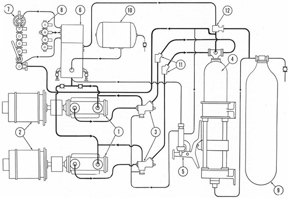 The power generating system consists of a group of units whose coordinated action provides the hydraulic power necessary for the operation of the main hydraulic system. It consists of the following principal parts: a. The IMO pumps (1) supply hydraulic power to the system and are driven by electric motors (2). b. The main supply tank (6)contains the oil needed to keep the system filled. c. The accumulator (4), as the name implies, accumulates the oil from the pump and creates pressure oil which is maintained at a static head for instant use anywhere in the system. d. The main supply and return manifolds (7 and 8) act as distribution and receiving points for the oil used throughout the system. e. The pilot valve, (5) is a two-port, lap-fitted trunk, cam-operated slide valve, which directs the flow of oil that causes the automatic bypass valve to open or shut. f. The automatic bypass and non-return valves (3). The automatic bypass valve directs the flow of pressure oil in response to the action of the pilot valve. The non-return valve prevents the oil from escaping through the open automatic bypass. g. Cut-out valves, serving various purposes throughout the system and non-return valves to permit one-way flow. h. The back-pressure tank, or volume tank (10), contains compressed air at a pressure of 10 to 25 pounds per square inch, which provides the air pressure on top of the oil in the main supply tank and maintains the entire system full of oil. i. The accumulator air flask (9) serves as a volume tank for the accumulator, allowing the air to pass to and from it when the accumulator is loading or unloading.
|
