USS Pampanito Bofors 40mm Gun Replacement
June 2021. Two Bofors 40mm guns installed for the first time since 1946.
BACKGROUND:
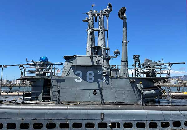
USS Pampanito is a WW II submarine museum and memorial on Fisherman's Wharf in San Francisco. The boat is owned and operated by a non-profit and receives no government funds. Our preservation goal is to make the submarine as complete and accurate to our summer 1945 restoration date as possible. This note is a description of the project to replace the missing Bofors 40mm gun, overhaul the gun we have, and a heartfelt thank you note to the individuals and corporations that helped made it possible.
In summer of 1945 Pampanito had two single 40mm Bofors guns (and a 5" 25 caliber wet mount, a twin 20mm Oerlikon, and small arms.) The boat was donated to our non-profit by the Navy in 1978 with no guns. Over the years the museum had acquired replacements for all the large caliber weapons except for a second single 40mm Bofors (M1 gun, M3 mount, no magazine rack). During Oct 2009 we acquired two part set guns. The first was removed from a minesweeper in the 1970s and retained by the ship recycler in San Pedro, CA until we purchased it (the "LA" gun). It is worth noting that when we got the breech ring cleaned up we found LST-727 stamped on it, maybe it served on that ship during the war. The second was in a coastal battery in Hawaii during the war, then given to a Hawaiian VFW post in the late 1960s by the US Coast Guard. The USS Missouri Museum acquired it in 2003, it was loaned for a short time to another museum, then donated by USS Missouri to USS Pampanito in 2009 (the "HI" gun). Both were in truly terrible condition, both were missing many parts. The LA gun was demilitarized with a cutting torch, the HI gun had every external nut and bolt fusion welded. Both sat in the weather for 40+ years without maintenance and showed damage from having fallen multiple times. The goal of this project was to create one gun suitable for museum display and interpretation on Pampanito. This note will also refer to the first Bofors gun found in Virginia and on loan from the Navy since the early 1980s (the "VA" gun, serial 27532, 1943.) We will also document the overhaul of the VA gun at the end of this note.
Restoration followed the U.S. Secretary of the Interior's Standards for Historic Vessel Preservation Projects.
We tried to get the gun as complete and accurate as we could while preserving as much of the historic fabric as possible. We have demilitarized it (made it unable to load a shell in the breech, or pass a projectile through the barrel). We also decided against simulated firing after investigating the safe Hollywood style gas, and sub-caliber munition (.50 cal or shotgun shell) systems.
Both guns we started with, and most of the guns we found in other museums had some common problems. They were not in full battery position, and/or had breeches partially opened, and/or hand operating levers out of forward latch, and/or partially turned barrels, and/or frozen side door latches and/or rusted out center cover. In most cases you must assemble and disassemble the gun in order shown in the manuals because of safety interlocks, interferences, etc. Once a gun becomes glued stuck with paint or rust with one of these problems it is much more difficult to disassemble. We also observed that the training and elevating handles are easy to break/remove and are missing from most museum guns. Finally, the sheet metal seats and foot rests were rotted out on most outdoor displays. We are trying these non-historic changes to mitigate these problems on Pampanito's gun:
- Added a non-historic long hasp lock on the hand operating lever.
- Store at horizontal elevation to prevent recoil caused by recoil spring fatigue.
- Side door lock loaded with water pump grease. Latch left unlocked.
- Added a set screw on the through hole opposite the spring loaded lock on operating cranks replicas.
- Galvanizing, and epoxy coating the seat pans, foot rests and sights.
- Procyon (hard coating preservative) on inaccessible interior places like cross tube. Liberal use of LPS 3 and grease on moving parts.
The leftover gun, mount, and foundation not used in this restoration were donated to Fort MacArthur (they are missing sights, sight crossbar flanges, most all of loader frame, loader platform, seats, handles, equilibrator rods, springs, spacers, nuts, covers, barrel spring, flash arrestor, training gear coupling.) The magazine rack from the HI mount was donated to Estrella Warbird Museum in Paso Robles.
This was a long project 2009-2014. Field striping and assembling a properly maintained gun with a minimally trained crew takes very little time. The actual work of dismantling these severely degraded guns took hundreds of hours of skilled work and a lot of specialized tools. We started slowly because a lot of restoration infrastructure work (servicing tools, acquiring tools, etc.) was needed. Most of the restoration work was done by volunteers that typically work a few hours a week. The schedule was also stretched because we needed a lot of specialized outside help. This required time both for recruitment, and for the logistics of moving the parts to and from their shops for restoration. Once in their shops our donated work was rightfully their second priority after paying customers slowing down delivery. The project was mostly volunteer funded so tradeoffs in time vs money almost always became time. In the end we exceeded our goals, but this was not a fast or easy project.
GUN ACQUISITION STORIES:
The Los Angeles Gun:
The Los Angeles gun acquisition was routine. During a visit to search for parts in August 2008, the owners of Merchant Vessel Machinery in San Pedro, CA mentioned that one of their friends that also runs a ship recycling business had removed a demilitarized Bofors gun from a minesweeper he had scrapped in the 1970s. With their help we arranged to see the gun and removed barrel. After agreeing to buy the gun, mount, and barrel we returned home. It it took some time to raise the cost from a mixture of ship funds, volunteer, and outside donations. Once we succeeded, the crew from Fort McArthur (coastal defense museum with a beautiful view in San Pedro, CA) generously offered to pick up the gun and store it until we could arrange for shipping. During September 2009 we flew down, rented a truck and drove the gun back to San Francisco.
The Hawaii Gun:
The director at Ft. McArthur museum knew how much was missing from the gun he was storing for Pampanito, and when he saw another Bofors gun listed on eBay he alerted us via email on a Friday 7 Aug 2009. The auction was scheduled to end on Wed 12 Aug which was only 3 business days away. We immediately contacted the seller via eBay to see if they would donate, asked if he knew the provenance (did he know its history,) was he an agent or owner of the gun, if not the owner who was the owner, requested better condition photos, asked if the barrel could be removed for shipping, etc. These are all the standard questions we want to know as curators before acquiring any artifact. We also started looking for estimates of the shipping cost to see if we could afford it (this was a mostly volunteer funded project and we were tapped out buying the LA gun). We contacted a major shipping company to see if they would donate shipping. Even though at this point we only knew the name of the town in Hawaii and a short eBay name, we contacted our colleagues at the USS Bowfin museum to see if they knew where the gun was, and if they could take better photos. The seller responded quickly with a one paragraph note (about 40 words) that described it as having been elevated since at least 1965 and not much more.
When we got the response we immediately sent another email requesting all the missing information. The seller responded with a 10 word note saying "Its been here at this museum as excess for five years." It was not responsive to most of our questions. The seller had still not identified himself, but the response from eBay had an email address embedded in the reply, and in the note the seller indicated he was from a museum. Together these were enough clues to be recognized by the Bowfin staff, they offered to go and see if they could get some photos over the weekend if the seller museum was open.
On Sat 8 Aug 2009 at 4:30 PM San Francisco time we received a long email from the seller. The email included for the first time the full information on the seller and and offer to sell the gun for $2,500. Ebay had delisted the gun because their policy does not allow online gun sales. About half way through the note we read, "The Bofors was in front of a VFW..that closed..and they were (There were two) given to the USS Missouri. In 2003, The Borfors was borrowed by the Centennial of Aviation celebration Comittee [sic.] for a static AAA gun display for the airshow done here. No one took the gun back and no one has come for it. The Bofors is in exactly the same condition it was when the VFW had it. Missouri slapped some gray paint on it but the rust was still coming thru." Whoa, what did he just write about a loan of the gun... We immediately sent an email to the curator at USS Missouri to find out what he knew about this. We also sent emails to the curator's branch at the Naval History and Heritage Command and the US Coast Guard curator to see if they knew anything about it, and especially to make sure the gun was not an outstanding loan.
We got an email written in the middle of the night from Missouri's curator. It turns out that USS Missouri Memorial had loaned the gun to the museum for a weekend event. The seller had picked the gun up, had the event, and then never returned it to Missouri. So this rogue museum was trying to sell a 2,500 lb gun that did not belong to them.
USS Missouri's curator contacted the seller on 10 Aug to ask why they where attempting to sell Missouri's gun. We both received a message the same day from the rogue museum director in which he claimed the gun had been abandoned and some other unsupportable claims of liability. Further, he threatened to scrap the gun in 5 days if the USS Missouri did not pick it up.
At this point the USS Missouri's curator and director offered the donation of the gun to the USS Pampanito if we wanted it (we did). The Pampanito crew worked on figuring out shipping and on trying to arrange a truck and crew to move the gun from the rogue museum back to USS Missouri until we could arrange shipping to the mainland.
Three days later (13 Aug) the rogue museum wrote to USS Missouri that they wanted a storage fee if the gun was not picked up by 16 Aug. Also that there was no forklift or crane available to load it, but it was on a loading dock. On 14 Aug the Missouri Curator asked where it was and tried to figure out the logistics of moving the gun. The rogue museum is located on an active airfield with post-911 security complicating access for any move of the gun. About two dozen emails and many more calls flew across the waters working on the logistics of moving the gun. Note that Missouri was two months away from a complex drydocking, this was not a great time for them to work on anything. The Pampanito crew spoke with the rogue museum director on 15 Aug asking for more time, and listened to his legal theories, his complaints about Missouri not paying to pick up the gun, and his blaming his landlord for the short deadline. He also recommended his favorite truck rental company, which we later called. They wanted $500 for one day of truck without crew, or $900 to move the gun from the rogue museum to Missouri, both seemed really high. The director seemed to understand that we were working hard to find a reasonable cost rental truck, crew, etc. We checked with legal counsel about his theories, they where not supported in the law.
On 18 Aug we got another email from the rogue museum director threatening that "the gun will be gone". By this point, after many more hours of phone calls and emails the Missouri crew told us that they would transfer ownership to us immediately if we wanted it, but they just did not have the time to continue dealing with the rogue museum.
A Pampanito volunteer offered to pay for the overpriced rental truck and started looking for a crew to move it as soon as possible. We contacted other museums, Naval Reserve, the USCG that operated in the area, a tug boat operator, and many others. By then we had two of three quotes we had solicited for pick up and shipping to the mainland. We informed the rogue museum via email on Tue 18 Aug 2009. We sent update emails with progress reports as the planning for shipment of the gun continued.
The rogue museum stopped answering emails or our daily phone calls. By 24 Aug we became concerned. On 26 Aug we got an email from the rogue museum saying "You were given a deadline 16 Aug, and then 21 Aug to retrieve this piece.
You did not.
There will be no further discussion. Please do not email me any further on the matter.
The gun is no longer in our posession. [sic.] If you wish to track the guns new owner, you may call Mr. xxxx at (808)xxx-xxxx"
We immediately emailed and left a phone message with the rogue museum director informing him we were going to contact the police.
We then called Mr. xxxx. I explained that the gun did not belong to the rogue museum and that now belonged to USS Pampanito. I expressed our hope that he had not paid for it, because it was stolen property and he would not be able to keep the money. I asked where the gun was. In dialect and an accent that could have come right out of a bad casting call for Magnum P.I. TV show, Mr. xxxx told me that the gun was moved up into the mountains where we would never find it. He then gave me a lecture about the Hawaiian high school buddy system. There were some disparaging remarks about mainlanders. It was surreal.
I then informed him that I would be contacting the Honolulu police immediately after the call. Mr. xxxx then changed his story and said that the gun had not yet been moved and that he would end his arrangement with the rogue museum director. He then repeated the rogue museum directors' assertions that the gun was abandoned property. He forcefully expressed his opinion that calling the police was "not cool man", and that nothing would come of it. He repeatedly said, "why don't you just come and get the gun". He also said we should move it quickly or it might just land up in HMS (a local steel scrapper.) He said "good luck dealing with the airport authority to get the key to the airfield". He suggested the police, "would not help a mainlander." He also said he was on a trip to the mainland and would be back in Hawaii in a couple of days.
We called the Honolulu Police department to inform them of the felony theft (even in bad condition it was worth thousands of dollars) of the gun. They heard the whole story and their interest really picked up when they realized that it was a large caliber (demilitarized) machine gun. They began an investigation, calling USS Missouri to confirm the story, etc.
We called HMS, and all the metal scrap yards we found through online search on the island of Oahu to ask them to contact us if anyone tried to sell the stolen gun.
We called the USCG Air Station across the airport to see they could help. They thought they would be able to after they checked out the veracity of our story.
We then got the idea to call the rogue museum's landlord, the State of Hawaii, Department of Transportation, Airports Division. This lead to another really special conversation. I called in to the general answering number at Honolulu International Airport and then explained to the operator who I was and that we are having a problem with one of their tenants at one of their secured properties. She surprised me by transferring me to the Acting Director of the airport. This is a big, complex airport, I was expecting to speak to a middle-manager, not the boss. I told him the whole story beginning with the loan of the gun. When I finished, he said he needed to verify the story, but that they would try to help us. I expressed my gratitude and understanding that this is not the Airport's responsibility, or their mission to fix the problem. He responded simply, and without any hint of irony, "I work for the State of Hawaii, we are here to help."
We did more online searches on the rogue museum director, the rogue museum, and Mr. xxxx that the rogue museum director had sent us to. Wow this was interesting, we found a grant application and it turned out that Mr. xxxx was second in command at the rogue museum and on their board of directors. Both held responsible positions, one was an instructor in the Air National Guard, one worked for a State Legislator. What a load of nonsense they had been feeding us on the phone.
On 27 Aug we heard from the airport that they were going to help. We informed the police, et al. what was happening. On 31 Aug the Airport Authority wrote that the gun was now safely stored under their control. We signed a contract with a freight forwarder pick the gun up on 31 Aug, they coordinated with the airport and it was picked up on 10 Sep. They called to let us know that they picked up two pieces, not one. When we got their photos we found out that between the time the Bowfin crew photographed the gun, and the time it was picked up by our shipper it had been tipped on it side and was broken into two pieces. It appears that it was knocked over rather than rigged down, we will never know for sure. After two months, 180+ emails, dozens of phone calls, a lot of aloha spirit from dozens of Hawaiians, plus $1,600 for shipping (discounted rate, fully donated by Pampanito volunteers) the pieces of the gun arrived at USS Pampanito on 22 Sep 2009.
The Virginia gun:
A Pampanito veteran, Leroy Van Housen, spotted a single barreled 40mm sitting in a storage yard near his home in Virginia during the early 1980s. It belonged to the Navy and was loaned to Pampanito by the Naval Historical Center (now the Naval History and Heritage Command.) The gun underwent some restoration when received, but it never got plausible sights, crank handles, rear cover, or bottom door. Oral history indicated there were some replacement parts during this restoration, but there is no documentation other than a couple of photos. The foot pedals, seats, sight crossbar, loader hood were seriously rusted. There were problems training the gun and elevation was rough.
Breech casing serial 27532, 1943
Upper carriage data plate Ser 4933, OrdAlts 1726, 1990, 1752C, 220?, 1975, 2913?
Carriage has MB E3103 stamped on it.
Breech ring E1251, B96-A77
Breech Y7, BC8
Barrel D50007-1, Tube No. 85252, Chrysler Corp., Gun Auto 40MM.M1, C.G.
RESTORATION PLAN/METHODS:
* The big picture:
We put the gun from Hawaii on the mount from Los Angeles. Most of the loader's platform parts and all the equilibrator springs (parts of mount) came from the HI gun. The case deflector chutes and frames are from the LA mount. Parts from both firing linkages were used. The LA barrel assembly was used with HI flash hider. Where duplicate small parts existed (surprisingly infrequent) we picked the better ones. The loader used was found in the Pampanito collection and modified to include a feed control lever. We also found a flattened loader cover in our collection that we were able to restore. We replicated handles, seats, foot rests, and sights. We could not have succeeded without both guns as parts sources.
- The forward foundation is a replica copied from the WW II original example on Pampanito that is now mounted aft.
- The deflection stop rail with muzzle lock aft was removed during the 1960s reserve period when they put in stairs leading up to the bridge. The deflection stop rail with muzzle lock forward was removed during the late 1980s or early 1990s, probably part of the attempt to match the pre-1945 refit gun configuration when they got the 4" 50 cal gun. The details now installed aft were probably done as part of the same changes and do not match any of the war time photos of Pampanito. We will need to replicate historically accurate deflection stops (elevation stop) and barrel muzzle locks forward and aft. We will need to add the spent shell casing screens forward and aft.
- We removed the training stop welding on the mount because it was badly placed and prevented maintenance of the loader platform frame bolts.
* All parts were photographed for documentation before removal. We also take progress photos as parts are re-installed. All replica and replacement parts are documented. Photos were taken and reports provided to Ship's Manager of all historic fabric that is removed from the shop and when it is returned. Nothing was lost. There are 1,500+ photos in the project notes (not including scans of manuals and drawings.) It is amazing how no matter how many photos you take, you always need one more view.
* We started by collecting photos of other original guns, mounts, foundations to guide the restoration. The topcoat paint scheme is a simplified version of Measure 32 (grey on sides and bottom, black from above, no countershading) scheme. We have not found evidence of red rings painted around lube points as was normal on Army guns in use on the subs. Pretty much anything that is not rubber, or a machined sliding part is painted on the outside. Nothing is painted on the inside, although there is mention of some internal painting in OD 5853. The magazine rack is not installed on submarine wartime photos.
See the Measure 32 on Submarines specification.
We acquired manuals and drawings. We put much of it on the web to share with others, and for our own easy access:
- 40 MM Automatic Gun, TM 9-1252 was purchased through a used book dealer, it covers the Army style M1 gun and M3 mount depot maintenance. This was the most important document to this restoration.
- 40-mm Automatic Gun, Technical Manual, TM 9-252 was borrowed and scanned. It is the field maintenance manual M1 gun and M3 mount. Together TM 9-252 and TM 9-1252 cover this gun. A second scan of TM 9-252 was donated by Easy 1 Productions.
- OD 5853, 40-MM Wet Mount Assemblies (Single) was found at the U.S. National Archives and Records Administration. This covers the modifications made to the standard Army gun for submarine installation.
- OP 820, 40 MM Antiaircraft Gun, is the Navy manual for the water cooled, directed, dual gun version. We scanned a copy in our collection. The gun itself is pretty much the same although the mount is quite different.
- Page 84, 40-MM Boresight MK 1 MOD 0 instructions, in OP 1449 Boresights and Boresight Telescopes was copied at NARA.
- Page 250, has more on the boresight in OP 1329, 40 MM Mount Mark 4 the Navy water cooled, directed, quad gun manual.
- TM 9-251 scan was bought for the Army dual gun on eBay. It was not useful for this project.
- A training video transferred from 16 mm film was donated by Gene Slover
- We checked OP 1289 at NARA (RG 74, BuOrd Tech Pubs), it is for the Mk 3 Mod 5 40mm which is a heavily modified, power training and elevating gun.
- We scanned some Navy waterjacket cooled versions of gun drawings at NARA. The M1 gun itself is the almost the same, the mount is completely different.
- We checked for Army M3 mount drawings and did not find them at NARA College Park, MD, Naval Heritage and History Command, Chrysler museum, General Motors museum, or the Army Center for Military History. Other Army units we contacted did not have them. There are probably sets of these around, but we did not find them, we are still looking.
-
We found a commercial company (Critical Past) that has digitized many WW II films, including some with views of the 40mm guns on submarines. We could not afford to buy copies, but the watermarked stills on their website are still useful. A list of links to the videos we used is at the end of this page.
* We created a Coatings and Lubricants Plan:
The ship's manager chose marine epoxy and polyurethane coatings. PPG/Ameron donated 235 primer and 450H topcoat (grey, black) and thinner. Cardinal Industrial Finishes provided powder coating powder. We initially cheated with rattle can spray on some of the small parts, but later recoated them with the marine coatings.
Most of the lubricant and soft preservation coatings were donated by LPS Labs:
- KB-88 and LST penetrating oil to free up frozen parts. After working with four different brands of penetrating oil we moved to LST.
- LPS 1 thin coat lubrication does not build up dirt.
- LPS 2 general lubrication where we want a thin film left behind, like 20 weight non-detergent oil.
- LPS 3 was used on machined parts for soft coat preservation.
- Procyon was used for fixed, unpainted parts preservation. It dries to a hard film coating a bit like type 2 preservative with a modern formula. We used this on the recoil spring, equilibrator springs, inside the barrel, and breech casing.
- Thermaplex Aqua marine bearing grease was used for general purpose lubrication, and where we were worried about wash out. For example packing the handwheel bearings, door lock, and external firing rod spring.
- Thermaplex Moly Grease. For roller bearings and slide.
- General Purpose Anti-Seize, and later Nickel Anti-Seize. On absolutely every nut, bolt or screw. Any two mating metal surfaces we want to be able get apart.
- Tapmatic #1 Gold, cutting and tapping.
- Strong Steel Stick, epoxy composite repair. Just two places, the pitting on top of breech under the data plate, and side of recoil cylinder.
- LPS Cold Galvanize spray (zinc rich coating) for touch up of plated parts.
- A generic rust converter acid/primer was used on the recoil spring before Procyon.
Measure 32 camouflage calls for black from above, grey from the sides and avoiding sharp lines in the transitions. We have photos from other boats showing sharp but large wavy lines, others with relatively straight lines spray painted by the yard in soft transitions, others with rough hand painted transitions. The one photo of Pampanito that shows the guns in summer 1945 does not show wavy hard lines. It also has sharp shadows and over exposed areas that make it hard to interpret how they handled the transitions. There is a line between simulating authentic war time crew painting (not shipyard) and just looking sloppy. Our first attempt is to do a kind of stippling with a lightly loaded brush in the transitions.
* Machined Surface Treatment Plan.
The Army manual shows most of unpainted parts were treated with US 57-0-2C, a phosphate type II class b black oxide finish (modern is MIL-DTL-16232G Type Z Class 3, a.k.a. gun blueing.) However this has poor corrosion protection and relies on frequent oiling that is not likely to happen in the museum environment. The wet mount version had many parts plated and some of the interior parts painted see OD 5853.
The chrome specified was prohibitively expensive for our restoration. We used nickel plate where needed on exposed machined parts, and hot dip galvanizing on some of the rougher exposed parts. We limited our plating to parts that showed signs of corrosion to minimize the expense and burden on our donors.
- Electro-Coatings Inc. coated the breech casing, sector gear, breech ring and equilibrator rods in nickel. They also did most of the parts we plated for the VA gun.
- Gold Seal Plating plated the many small parts in nickel.
- Pacific Galvanizing did the hot dip galvanizing (zinc plating), for example the seats.
* We searched for the spare parts we needed on the ships in Susuin Bay Reserve Fleet. We got what we could (bits of sights, rusted seats that we landed up throwing out, a seat post we used on the 5" 25 cal restoration, foot rests we did not use for this project) from 5" 38 cal guns on USS Nereus, and USS Sperry. We also checked USS Pyro, USS Tulare, USS Thomaston, USS Point Defiance and USS Vancouver which had 3" guns from the 1970s. We also inspected, but did not find parts for our project on the decommissioned training gun behind Building 1 on Treasure Island. We found in collection without documentation some parts (Navy style sight, two loaders).
* Acquired or replicated the tools we will need to safely disassemble and reassemble gun and mount.
- Midway through the project Battleship USS Alabama donated a gun tool box and a spare parts box. Note these cover the M1 gun, but not the M3 mount. This was really nice of them, and saved us a lot of time creating replica tools. We sent them a WW II laundry machine kit for USS Drum as a thank you. (A kit because it was dismantled when removed from a WW II submarine tender as spare parts for restoration of the machine on Pampanito. They restored it and it is now on display on Drum.)
- Battleship USS Massachusetts donated a shell pusher.
- We bought a barrel wrench (flash hider end) on eBay. We are still looking for the barrel holder (breech end).
- We bought a set of loader installation tools from International Military Antiques
- We built an improvised setup to remove/install equilibrator springs. See page 270-271 in TM 9-252.
- We built equilibrator spacers, our were made out of 1/8" mild steel with a hole for a bolt instead of 1/2" thick steel. See page 48 of TM 9-1252.
- We made several small custom tools that were needed to remove parts out of their normal positions.
SAFETY:
- If not properly bolted to the deck, the 2,500 lbs. gun can be easily tipped over (including unpredictable seismic events). The more elevated the barrel, the less stable it is.
- Unless assembled with equilibrator springs installed, the gun can depress from its own weight very quickly (approximately 1,500 lbs just in the gun and barrel). Without the barrel installed, the equilibrators springs can elevate the breech casing very quickly. Both are really dangerous for nearby personnel, and are bad for the gears, etc.
- There are very strong springs in the equilibrator, barrel recoil, breech operating, and loader mechanism that must have their spring force applied, and released in a slow, controlled manner. All can be very dangerous.
- Although neither gun had lead paint (we tested), we were careful not to breath or spread the removed paint dust that included a zinc chromate primer.
- For safe lifting/rigging the gun see the photo NARA 80-G-468227. (Pick on the breech casing and let the trunnions carry the weight of the carriage.) The elevating handle must be tied before lifting.
- We investigated, and strongly recommend against simulated firing based on gun powder or other explosives in museums.
NOTES ON FROZEN/WELDED BOLT REMOVAL:
The bolts on the HI gun were particularly hard to remove. This was not delicate fine art conservation work in most cases. We could not save the parts without sacrificing a lot of the fastenings. First we removed the paint as much as we could. It is easy to underestimate the holding power of old paint and rust. We used scrapers, wire brushes, files, dental picks, plastic abrasive wheels, wire wheels, fiber glass brushes, and on some removed assemblies sand blasting. Near the end of the project we discovered Evapo-Rust and soaked some of the mechanically cleaned assemblies to remove inaccessible rust. The welded ones then had as much of the weldment broken off as possible with cold chisels. Sometimes that was all that was needed, but in most cases we then used an angle grinder, die grinder, and hand files on the weldment. In a few cases we used air-arc gouging to remove the weldment, this is fast, but also causes collateral damage.
They were then soaked with penetrating oil. We found soaking over time made a big difference. We gently tapped them straight down with a hammer. We applied manual socket wrenches, and sometimes air impact wrenches if the heads were in decent shape. If they did not come out, we then heated them red hot, let them cool, soaked in penetrating oil and tried again. This is really helpful, but it changes the characteristics of the metal (softer in most cases.) Repeat above as needed. We used a gas torch for heating during most of the HI+LA gun, only after it was done did the museum receive the donation of a Mini-Ductor induction bolt heater. On the VA gun we used this for almost all the bolt heating as it is often safer and faster than the torch. If the heads were eroded or not enough was left after removing the weldment we tried special damaged head removal sockets followed by locking pliers. At this point, if we had not sheared the bolt off already there was usually not enough head left to grab. With no head, we ground the top flat, punched, drill it out with a left hand drill, and used a screw extractor. In a few cases we drilled the fastening out close to its inside diameter and picked out the last bits of thread. This mostly worked without damaging the attached parts other than when we used heat. We tried welding a nut on a broken tap, but did not get it right, others successfully use this technique a lot. We used a lot of heat getting these guns apart, it is good that no one will ever try to fire them because some of these parts might just self-destruct.
Stuck nuts were very similar to the the bolts above (remove paint, rust, penetrating oil, heat if needed...) We did not have a nut splitter, but we did break some off with a cold chisel. We learned a neat trick that worked a few times. Hit the nut on opposite sides with two hammers at the same time. It causes the nut to become a tiny bit oblong and sometimes frees it up.
After removing stuck bolts, studs or nuts, we used a thread restoration tap or die on remaining threads. Note these are not normal taps and dies, and they are less likely to cross thread, seem to do less damage, and remove less material from the parts. We had one broken rethreading tap that we could not remove from a bolt in the stop pad. We tried welding a nut on the end of the tap trick without success. In theory someone could drill this out with a cobalt drill, or do a better job welding to the end, but access is really poor so we left it in. We did use warm citric acid, and later cold Evapo-Rust to remove rust from some parts with moderate success. Only two of the threaded holes we worked on were beyond salvage (sight crossbar mount holes on top of breech casing), for these we drilled, tapped, and installed threaded inserts.
Taper pins are tough to remove if they get stuck. We used the basic methods above (remove paint, rust, penetrating oil, heat if needed...) Often they had too little left to try to pull out on the fat end. Tapping on narrow end blossoms them out if they do not release with the first sharp blows. Then we had to grind them flush and try a properly sized pin punch centered on the pin. If we landed up drilling them out, the hole needs to be restored using a taper pin reamer (thank you Alvord Polk). Some of these were in awkward locations, we feel pretty lucky that we did not break any of reamers in place.
Absolutely everything was re-installed with anti-seize compound. We started with LPS General Anti-Seize, and later switched to Nickel Anti-Seize.
We did not have very many problems re-installing threaded parts. In almost all cases running a re-threading die or re-threading tap was sufficient to solve the issue. However, the flash hider threads on the LA barrel were seriously beat up. After we got them as good as we could with an OTC outside thread die repair tool, and a thread file, we screwed the flash hider on as far as it would go, and then hit the sides of the nut hard (the flash hider.) The nut rolled a little farther and we repeated, over and other. It fixed the threads.
Notes on penetrating oil. Our old time machinists friends each had their favorite product. We used three of these before we settled into using LST from LPS Labs. It is oil rather than solvent based so it does not damage rubber and plastic, it smells better, it does not stain the hands like the red solvent based products, and it works really well. We did not try it, but others use candle wax melted into just below red hot on bolts.
COMPLETED WORK LOG:
This section started as about 150 sequential log entries of a paragraph or two each. It was transformed into something much shorter by removing all the entries that did not have something special to document, or to learn from the methods used, or an adverse outcome. For example, the original documented all movement of historic fabric off the pier and its return, when we cleaned and lubricated, etc.
- Documentation of "as received" condition. This was mostly photos, and as is usually the case during museum projects you can never take enough. The photo documentation continued with every step and is omitted from the rest of this abbreviated log.
- We tested for lead paint on multiple locations on each gun with swab type test kits. No lead was found on the LA or HI guns. However, when the seats from Battleship Texas were tested on arrival they had lead paint. Bay Ship & Yacht shipyard donated blasting to bare metal of the seats by their properly trained and equipped crews. After testing we removed enough loose paint, dirt, etc. on both guns and mounts for assessment.
- The notes on difficult nut, bolt and screw removal are mostly not repeated in this log. Particularly on the HI gun and mount, pretty much every nut, bolt and screw required a lot of work to remove. At minimum, all the exterior bolts and many other parts had been welded so the weldment had to be broken, ground or burned. When the weld was deep, the fastener had to be drilled out. On most projects using a grinder or torch to remove a bolt is an unusual event, but here it was the norm. The LA gun was generally easier, but even here aggressive measures where frequently needed, and there were bolt heads that sheared off with what seemed like moderate force.
- We followed the order of parts removal and replacement as described in TM-252 and TM-1252 whenever we could. Note that for the parts that are the same as the Navy water cooled gun, OP-820 had better instructions and illustrations. When approaching a new area we tried to read all three books.
- We started disassembly on the HI gun because we wanted to depress the gun and barrel to make the gun safer and easier to handle. Once we removed the covers and exposed elevation gear train we found the pinion gear was a clot of rust and is missing whole gear teeth. So it could not be used to depress gun.
The plan changed and we instead dismounted both guns. Because the HI gun could not be depressed, it was difficult to release the equilibrator rods from the gun. We created replica spacers, but the rods were still under pressure when released. Note that the pins on equilibrator rods should be placed from above to make them easier to remove (one was inserted from below and was really hard to get out.) The trunnion bearing cap studs unscrewed from the mount before the nuts turned, it was not elegant, but we got them off. Jake Roulstone later removed the welded nuts from bearing cap studs without additional damage to the studs. We were able to salvage one of the big castle nuts and two of the studs.
- We removed what was left of the loader platform frame, deck, foot rests, shell chute and rails, and magazine rack from HI gun. The LA gun had a shell chute and rails, but the loader platform consisted of the loader platform frame caps and a small cross piece. The magazine rack we did not need was donated to the Estrella Warbird Museum in Paso Robles, they reciprocated by donating a Bofors 40mm magazine with four replica drill shells to Pampanito.
- Ralph Waller used gouging air-arc to remove the weld around the barrel sleeve on the HI gun. The spring gently pushed it off. A few inches of the spring came with it. We picked away at another two coils, maybe 5 out of 18 came out easily. The rest of the the spring remained in the gun frozen with a concrete made of sand and rust. Over subsequent weeks we soaked the mess with penetrating oil and picked away at it with longer and longer screwdrivers. We bent the end of a long screwdriver to make a breech casing and recuperator (recoil) spring rust picking tool. Bits of spring would slowly come out. It got harder to do as we got deeper into the breech casing, as much at 18 inches, because there was very little clearance around the spring. We tried flowing citric acid 10% solution with a small fish tank pump through the rust, but it did not remove very much and was abandoned. This might have worked better if we had used a stronger acid and heated it. We did not know about chelating agents like Evapo-Rust at this point in the project, it might worked better and certainly would have been much safer. It was miserable, slow, tedious work, but we eventually got the last of the rusted spring out.
It still required a lot of scaling inside the spring housing to provide clearance for the recoil spring washer and breech end of the barrel. The recoil spring washer only came out later with the barrel.
We also used air-arc to remove other welds that would have been hard to grind out.
We broke a lot of sand/rust/dirt mix out of the muzzle of the barrel HI gun barrel with an air hammer gun.
We removed the remains of the rear cover hinge pin (its taper pin later needed to be drilled out, and hole reamed from the breech casing.) It was completely rusted through in the center.
- Removed the external firing linkages from LA mount. These included delicate parts that were damaged on the HI mount so we were being really cautious. The spring was solid with rust and we broke one of the shafts during removal. Jake Roulstone took the removed pieces and was able to complete the disassembly without further damage and he repaired the broken part. The four bolts that held the lever bracket near the trunnion were brass for some reason even though they secured two steel pieces. They were steel on the LA mount, we replaced them with steel.
- The side doors on both guns were frozen shut and had to be opened to remove the internal components. In both cases the doors had been locked, and the spring and locking pin were frozen in place. After our first attempts to open the locks, we tried to rotate the screw hinge pin without success. Eventually after picking away at all the crude we could access, repeatedly flowing penetrating oil, and heating and cooling multiple times, we were able to move the locks without breaking anything. Even then, getting the side doors open was difficult and required wedges and hammers. These have been a problem to get open in other museums as well.
- We opened the covers on LA mount traversing mechanism, everything was well coated with grease with no obvious signs of corrosion. We cleaned and lubricated the training gears. We did not remove much here since it trained smoothly. We removed and straightened the bent training handle. The locking pin on these handles is spring loaded and normally gets pulled out with a knob, however the knob was broken off and missing on both elevation and training handles. We cleaned and loaded the top (handle) gear box, and the middle space where an automated guns gears go with water pump grease. Removed top cap from lower gear, cleaned, inspected and reloaded with grease.
- Elevating assembly on LA mount. After removing the hand operating sleeve that holds the elevating handle on the shaft is was clear that the gun was dropped here. We straightened the bent remains of the handle. The hand operating gear was sheared off. With some effort, it was completely frozen and full of sand and rust, we removed the bronze operating gear from the HI mount and put it into the LA mount. We drilled and tapped this new combination of parts for the training hand operating sleeve and installed a newly made 10-24 fillister head lockscrew. Removed the broken bolts from the hand operating shafts of both guns. Took the gear washer from the HI hand operating sleeve and mounted it with new screws. Fixed bent edges on the hand operating sleeve. We later plated the hand operating sleeves.
We removed the hand operating assemblies, opened the covers and removed excess grease from both elevation and training gears. The interior parts look remarkably good. However, even after disassembly, cleaning, lubricating, adjustment of the worm gear, the training gear was hard to turn.
The case casting itself appears to be slightly bent, it is amazing that this was dropped with enough force to bend it, and that it did not break. We did not try to straighten it. The bronze gears were all sharp and fresh, we think this might loosen up a bit as the gears wear in mesh. Cleaned and coated with Procyon the inside of the cross tube that holds the elevation gear.
- Ralph Waller replicated the two bushings that were rotted away on the firing pedal. He then took all the bits and pieces from both guns, some pieces of steel tubing we bought, and a replica stub for the piece that holds the foot rests and welded them together into a loader deck frame. He also repaired the completely lacy (rotted out) spent shell chute parts. We decided to create the stub that holds the foot rests from a single piece of solid stock instead of a solid piece inserted a tube like the badly degraded original. I counted 15 pipe and tube welds in the restoration of the loader deck frame. This might have been easier to replicate from scratch, but he preserved as much original material as possible. Bay Ship & Yacht donated blasting, and primed 13 pieces that were too big for our blast cabinet. For example the completed loader platform frame, expended shell chute, etc. These were then top coated by our crew with Ameron gray. Note that with all the welding, etc. the fit-up of all the parts attached to the frame was tighter than would have been on a normal gun (chute frames, rear chute, rear intermediate chute, forward intermediate chute, front chute, chute cover, loader deck, deck plates.)
- We opened, drained, and left open the recoil cylinder before working on freeing the bolts and recoil locking cylinder that hold the recoil cylinder on HI gun. It was filled with a green viscous oily liquid, probably glycerin. We were afraid of this exploding from over pressure if it was incidentally heated while working on the bolts. We removed recoil cylinder anchor bracket and freed the recoil cylinder body so it would not prevent movement of the breech. The piston was frozen in the case. Then we had to wait until we got the gun in battery position to finally remove the recoil cylinder from the breech ring.
We moved gun to battery position with use of hydraulic ram. We had lubricated everywhere we could reach and tried simple levers before we resorted to the hydraulics. It took several tries after many hours of cleaning, lubricating, etc.
After removing and cleaning the recoil cylinder, we saw there was leakage through the heavy pitting on the upper side of the recoil cylinder case. When we later disassembled it there was no sign of heat or corrosion damage inside. We filled the pitting on the outside of the case with LPS Strong Steel Stick, an epoxy composite. We were worried that even with a good TIG welder the thin metal would collapse and the machining would have been difficult. It seemed less risky to the historic fabric to repair this way. We cleaned and plated with nickel the piston rod because the original chrome was largely gone on the exposed areas were rusted and pitted. We probably should have welded and turned the pitting, but choose not to. We nickel plated the locking ring and spindle lock.
We refilled the cylinder with 100% marine hydraulic oil when re-installed just for interior corrosion protection, the gun will not be fired. It should have 60% hydraulic oil and 40% recoil oil light. It uses approx. 1.2 pints, filled at 25 degrees. Fill with the needle valve open, elevate and depress a few times, then reset the needle valve by closing it and then unscrewing it one-third of a turn. Lock wired the ports.
- The breech block removal saga. After quite a bit of work, we got the breech block on the HI gun to move up and down about 3/4". However, the breech needs to be in the fully closed position to remove the outer crankshaft with the breech, inner and out cranks, operating spring, before you can remove the breech. The extractor pins were blocking the breech from closing. They were frozen, and could not lay into the grooves in the barrel in the normal closed position because the barrel was frozen about 165 degrees out of position. We have no idea how or why it was left this way, but it made everything much more difficult. It became clear that we needed to remove the barrel before we could remove the breech. We had to get the breech fully open to get the barrel out. So we switched to working on freeing up the breech ring barrel catch. Once we got that done we worked on the frozen check plunger. We then got the extractor spindle arm moving back and forth, but without moving the extractors.
By then it turns out that we had moved, lubricated, cleaned, pounded, etc. the breech enough times that the breech closing spring was now very strongly trying to keep the breech closed. Once we understood what was going on, we used force to open the breech which allowed us to push the extractor pins in to lock the breech open. This also kept the extractor pins out of the way so we could start trying to turn the barrel and remove it. Note, the breech closing spring is really strong, when the breech was first freed there was a very strong snap. Had we not been being very vigilant about the possibility of movement we could very well have been hurt.
- We tried but could not turn the barrel. We moved the gun back to about 10% recoil so we could get access to the forward end of the breech ring where the barrel enters. We removed the breech ring barrel abutment and used the hole to clean and oil. We cleaned, we heated, we applied lots of penetrating oil. We heated the spring casing near the spring retainer. We reached and cleaned everything we could get to. We went back and forth between battery and 10% recoil. We repeated everything above. We lifted rear end of gun with a chain hoist to let gravity pool the penetrating oil around the end of barrel in the breech ring back and forth. This went on and on getting more and more aggressive with the force on each attempt to turn the barrel. We were stuck for a while and switched to working on removing the loader, etc. We kept repeating everything above, oil, heat, movement forward and aft, applying more force. Hammers, bigger hammers, forklift, etc. Eventually we bolted the breech casing to our platen welding table and used 3/8" chain cow hitched and tack welded to the barrel with a 10 foot piece of welded square tube as a lever. With a 210 lb volunteer shock loading it by jumping up and down we really were worried about breaking something. It finally rotated just a bit, then it was just a matter of rotating it back and forth a little more each time with lots of penetrating oil. After re-installing the breech ring barrel abutment, more cleaning, better alignment and lots of movement back and forth the barrel came out of the breech ring on HI gun. It could not immediately be removed from the breech casing because the recuperator spring seat washer was rusted frozen into the breech casing. After yet more heat, oil and lots of scraping, we finally removed the barrel with recuperator spring seat washer. Once it was out, we found sand and rust filling the interrupted threads, it still amazes me we did not break anything.
- We now had the barrel out, extractors out of the way, breech closed and breech ring in battery position. It was relatively easy to remove the outer crankshaft with the breech, inner and outer cranks, and breech closing spring.
- Removing the loader on the HI gun. We moved breech ring into battery position. With cleaning, heat and a custom tool we got the loader tray bolt out. We removed automatic loader retaining cap screws without fuss. We cleaned all the rust, paint and crude we could reach outside and inside where the loader touched the breech casing. There is not very much access inside with breech ring, etc. filling the space. We tried but could not move the loader. We kept heating the seam and cleaning what we could reach inside with longer and more flexible tools, but we could not get the loader to move. We also could not get the hand operating lever to move. We used more and more force, eventually using a hydraulic ram to push loader. This finally freed the loader and moved it one inch. All the space on on the sides that was exposed by this movement was full with sand and rocks. We cleaned out everything we could get to. We kept cleaning, oiling and moving what we could.
One of the brackets on the sight mount we were pressing against with the hydraulic ram broke. The 1/2" bolts bent, however we got the loader out. It turns out that the loader was caught on the lever shaft arm of the hand operating mechanism. Possibly because of some of the bigger rocks we found in here, possibly because the breech hand operating handle was not fully forward laying everything flat. It broke the 1" shaft. We found all the space between the loader and the breech casing walls was full of sand, rock, and rust. When this was cleaned out we could see deep pitting of the breech casing. Tom Grove at Fort McArthur fixed the broken hand operating lever shaft. The sight crossbar mount was weld repaired by Ralph Waller. Later the top of the breech casing was sanded and filed flat, two of the bolt holes re-tapped, the other two had thread inserts installed. Installing the thread inserts was fun because it was the first use of a newly donated Hougen magnetic drill and Tapmatic attachment.
With the loader out, the breech ring came out without too much fuss.
- The HI gun hand operating lever. We had to drill out the frozen set screw, and then the pin on the hand operating lever. Something about the metal in this pin dulled HSS drill bits really quickly so we switched to a cobalt drill. Even so, our newly donated Drill Doctor drill bit sharpener was essential. We removed the hand operating lever and straightened it. Later we created a replica hinge pin out of stainless steel to replace the drilled one. The hand operating lever shaft was difficult to remove. The screws holding the operating lever shaft were very hard to remove, but we eventually go them out. The bronze bushing on the operating lever shaft released from the breech casing before the shaft. Re-installing this flush was difficult. The threads on the lever rod crank had been destroyed by the demil welding so we used the one from the LA gun. We heated and bent out to normal shape the hand operating lever catches both forward and aft. After cleaning out the paint, some oil from the outside the spring loaded detents worked so the latches were not removed.
- We rounded the bent-in forward end of equilibrator casings on the HI mount in preparation for spring removal. Again it looked like it had been dropped here, or smashed with a forklift. The rear equilibrator rod bushing on one of the LA gun equilibrator cases was cracked. (The LA mount did not have springs, nuts or spacer.) Cleaned the inside and outside threads of the exposed ends of the equilibrator rods on the HI mount. We built an improvised setup to unload the spring force for removal of equilibrator springs out of 1.5 foot of 3/4"-16 TPI threaded rod, nuts, a thrust bearing, two hard service washers, and a custom welded 1-1/2 deep socket (should be 1-15/32). It was fun when we removed the springs, nuts, spacers, rods and rod couplings because our improvised tools worked perfectly the first time.
- Removed the cut and bent top door from LA gun (HI gun's was missing.) At first we tried heating, flattening, and filling the holes. We could not get it flat enough to sit well on the breech casing. So we cut the uneven, rear 1/3rd off and replaced it with new plate. Luke Stevens delicately TIG welded it with minimal distortion. We created a new fixed handle and salvaged all other parts. We nickel plated the base piece. The taper pin holes on the door that came from the LA gun and the breech casing from the HI gun overlap, but do not line up.
- On LA gun: Removed rear cover and separated the case deflector chute. Freed up some motion on the hand operating lever. Opened the side door. Moved breech to battery position. Used the hand operating lever to get the breech to move a bit, the closing spring was limber. Note that a lot of the parts in the LA gun are plated inside as compared to black oxide on the HI gun. This made it easier to get apart. Moved breech to closed position. We removed breech closing spring, outer and inner cranks, and breech. Freed up the barrel lock. Removed the hand operating lever.
We got the loader bolt turning, but with more force than should be necessary, even after oil, heat, tapping on the loader tray. We moved the breech ring and loader tray a bit to see if this would ease the pressure without any real change. We created another, harder loader bolt wrench to keep moving it back and forth. With the breech closing spring out, we were able to remove the locking screw and then the loader bolt spring cover and spring with offset tools that we made. We then pushed the loader bolt out from the spring side with a pin punch. We removed the loader and breech ring without any further drama. We then removed the breech from the breech ring.
We removed hand operating lever shaft, etc from the LA gun. It was not smooth, but it was much easier than the HI gun.
- Ralph Waller reformed the crushed (flattened) sheet metal loader cover found in our collection.
- Removed breech ring stop from both breech casings. Removed most of the internal firing mechanism from both guns. Removed side cover (door) from HI gun.
- At this point we where still not sure which breech casing would be the easiest to repair. Both required welding and machining that could not be done at Pampanito. Northrop Grumman Marine Systems volunteered to help. Below is a list of big issues with each breech casing at this point:
HI breech casing:
- Needed to remove remains of coatings, rust, etc.
- Drain hole on spring casing (forward part of breech casing) was wasted away. It needed a round insert and horizontal boring to the correct internal diameter.
- Inside of spring casing forward (muzzle end) needed weld build up to replace wasted material and damage from the weld between the spring casing and the barrel slide sleeve. It then need horizontal boring to size so the barrel slide sleeve could move smoothly.
- Removal of 6 set screws (from outside) and 6 holding screws from the burnt and removed rubber stop pad inside on the forward face of the casing.
- Remove taper pins on safety plunger handle, and extractor releasing lever still attached.
- Deep pitting on the internal rails.
- Top forward, by way of the threaded holes for the top door and sights was bent upward.
- Possibly build up some of the most severely pitted side walls.
or
LA breech casing:
- Need to remove remains of coatings, rust, etc.
- Repair six cuts on top of breech casing without excess heat distortion.
- Insert repair cut in spring casing, and bore interior so a barrel slide sleeve could move smoothly through it.
- Either repair cut right trunnion, or replace with right trunnion taken from HI case.
- Repair, or swap the damaged sector gear (whole teeth rotted away) with the one from the LA case.
- Remove taper pins on safety plunger handle, and extractor releasing lever still attached.
- Possibly some repair of internal rails.
After NGMS had soft media blasted both breech casings it became clear that although the HI breech casing had deep pitting and other serious problems, it was straight and plumb enough for reassembly in a way that would have been very risky after welding the cuts on the LA gun. It also avoided the sector gear and trunnion repair. We also decided against weld repairing the track inside the breech casing because the machine work to true it up afterward would have been difficult. They created an insert and repaired the hole in the spring casing.
Between NGMS and our crew we finally got the taper pins out of the safety plunger handle (safe, single, auto lever), and the extractor releasing lever (forward right handle.) We removed the attached handles and internal parts completing our disassembly of the breech casings. The taper pins were difficult on both because taper pins are generally difficult, but also because of the corrosion and the distance from the edge of the breech casing made access difficult.
Note all the bronze bushings for handles were initially frozen on both guns. Sometimes the bushing released from the breech casing before the enclosed shaft. This added a challenge when it came time to reinstall them because we could not use an arbor press in situ to get them in straight. We also accidentally melted one one of the bushings while trying to use heat to release its shaft. We chose to re-install the originals rather than create new ones as would have been appropriate after torch heating in the spirit of preserving historic fabric. It would have been easier to replace them with new bushings.
Oakland Machine works welded the muzzle end of the spring casing, and did the horizontal boring on the spring casing. Really beautiful work on a large and awkward shaped object.
The breech casing then went to Electo-Plating Inc. for cleaning and nickel coating. When it came back it was really hard to imagine that this was the same piece as in the photos from Hawaii.
- The foundation that came with the gun from LA is a real foundation, but not the correct type for a submarine installation. It would hold air and does not match the photos or original example from Pampanito. So Leo Hoenighausen from Holt Tool and Machine, Inc. created a replica of real foundation from WW II on the boat. He volunteered to create this before we visited his shop. We suspected he was different when he came to measure the foundation on the boat with the largest high precision caliper we had ever seen. Our suspicions that something was up increased when he created a template to test the bolt hole pattern that was itself a work of art. Only when we visited his shop did we discover we had asked an ultra-high precision CNC machine shop that regularly creates incredibly complicated space qualified parts in exotic materials to do a ship fitter's job.
- Disassembled the rear door from the HI gun. This required some hard rock mining on the rust/rock encrustations. I broke (accidentally melted) the brass stud for the recoil indicator pointer. Disassembled the recoil indicator from the LA gun. On this one there was no pin, or hole in the top of the tension nut.
- Gold Seal Plating nickel plated a large number of small machined parts. We focused this effort on parts that were external, and ones that had suffered corrosion damage previously.
- We used a donated outside thread repair tool from Owatonna Tool Co. on LA barrel flash hider threads. They have been pretty bashed up before we got them. We also used a classic 4 sided thread file. Once we got past the obvious bad thread damage near the muzzle, it hung up about 1/2 way home. The flash hider rolled onto the HI barrel so we knew problem was the LA barrel. This is a 2.5625"-12tpi thread. So we learned to hit the sides of the flash arrester (the nut) on four sides, hard. This would allow us to roll another 10 or 20 degrees until it got stuck. We kept this up until it was all the way home and the threads were fixed, we can now roll it on and off with ease. We installed HI flash hider with a new gasket and replacement hardened steel set screws.
We cleaned the rust from recoil spring with wire brushes, then an acid/primer rust converter, followed by Procyon. We did not disassemble the barrel assembly.
We cleaned breech end interrupted threads, and deburred all the defects we could feel.
- Reinstalled hand operating lever internal assembly. We had to ream the bushing to loose fit after reinstallation. Removed HI trigger from bushing that had come out with it. Accidentally melted the LA gun's bushing while trying to extract the trigger shaft.
- On the loader found in Pampanito's warehouse, we drilled a stop lever hole and drilled and tapped for stop screws. Milled the round impression for the detent balls. Removed the thumb lever from LA gun loader. We used a new stainless ball bearing and spring. After the modifications we plated the back with nickel. To adjust the linkage, shorten the intermediate rod until there is no play so the movement of the lever is fully transmitted to the stop. We did some basic cleaning on the rest of the loader and left it mostly coated with LPS 1, and in some places water pump grease. Note we did not fully strip down the loader, just cleaning and the mods to the back to add the thumb lever and plating of the back. The assembly screws are not plated. We checked adjustments as described in 298783.jpg.
After we installed the loader in the breech casing, we notice that the holes for the loader retaining cap screws where missing. This is the loader we found in our collection, it may never have been installed in a gun. With Luke Steven's help we drilled and 5/8"-18 tapped for the loader retaining cap screws The frame is silicon bronze qq-c-593.
- Removed damaged stop pad holding machine screws. Removed damaged set screws from stop pad bolts. I broke a rethread tap in one of the bolt holes. I tried the welding a nut to it trick, but I did not get it out. Turned down the heads on replacement stainless machine screws because pan head 5/16-24 3/4" was not available. Installed new old stock stop pad from USS Alabama donated spare parts kit.
- Replicated sector gear stop pads in N-Buna rubber and reinstalled with original screws. Note that one of the guns had rubber pads and the other had leather. Neither had washers which is surprising. Installed elevation top carriage pointer originally from HI mount.
- Received two Navy style seats donated by Battleship USS Texas. Ralph W. replaced the rotted out backrest on one with a replica. We purchased and modified replacement seat pans to replace the rotten ones. Galvanized the seat pans, and nickel plated on the rest of the seat post and adjustment (machined parts) for corrosion protection. The Navy style seat posts are smaller than the Army style. One of the seat back slides had a 3/8"-16 NC, 3/8" long, fillister head screw that captures the seat/seat back slide on the seat post. The other has a 3/8"-24 NF hex bolt. It is strange that one is NC and one NF.
Later we created replica Army style M3 seats with purchased seat pans and installed with original Army mounting hardware that we restored.
- Installed side cover, internal firing mechanism, internal hand operating lever linkages, breech release lever. We used new old stock springs from the spare parts kit.
- Removed remains of taper pin from breech casing rear cover hinge. Drilled and taper reamed the broken rear door hinge pin taper pin hole. Installed rear door. Installed deflector chute and indicator after plating rear bolt, indicator, and indicator nut.
Removed remains of the taper pin from top cover hinge on breech casing. Flattened the top of breech casing by way of the top cover hinge with a belt sander and hand file. Re-tapped top cover mounting holes, but they are no longer parallel to the top surface, and are a too far forward. This prevents the cover from locking open. Covered exposed steel with zinc rich primer.
Drilled, tapped and installed thread inserts into rear two of the sight crossbar mounting holes that were stripped. This was fun because we used a newly donated Hougen magnetic drill and Tapmatic attachment. Ground almost flush the bottom of thread inserts. Retapped the front most pair of mounting holes for the sight crossbar.
Fitted side door opening in breech casing on bottom side. Covered exposed steel with zinc rich primer.
Removed one good, and two broken index pins on the top of the working breech casing. Used a left hand drill and easy-out for the broken pins. Removed two good pins from the LA breech casing. These are not in the manual, but are on both breech casings. We do no know what they are for, but we guess for a gunner's quadrant.
- Equilibrator casing and springs. Sand blasted equilibrator spring cases. We replicated the missing covers (waterjet cut disks, lathe), cut hinges from purchased stainless steel piano hinge, and welded them on. We created spring metal latches, but were never really happy with our tempering. Next time we make springs we will send them to a professional for heat treatment. Riveted the latches. Hand peened the hinge pins. Plated the casings in nickel.
Degreased equilibrator springs, separators, rods, nuts. Cleaned threads with rethreading tap and dies on rods. Plated nickel rods except for threads. Springs and separators are covered with Procyon.
The installation of the springs on the right equilibrator went without a hitch using the same improvised tools we used to remove them. On the left side the spring nut got very hard to turn when nearly fully in the case. It rolled on the rod without a problem before installation. The rod was covered with anti-seize compound before installation and started without problem. I do not know if some contamination got in the threads, or the threads were damaged during installation, or they were just too thin (rusty before we cleaned up the threads) and could not handle the pressure. In any case, it is frozen and the threads are likely damaged on either the equilibrator rod, or the spring nut or both. We left them in place, but it will probably be hard to get out and hopefully the threads are not as badly damaged as I think. We have an extra equilibrator rod from the other mount (in mediocre condition), but we do no have an extra nut (only one of the donor guns had springs.) Ship happens.
- On the choice of which breech ring to restore. The HI breech ring was really rusty, it is amazing we got the barrel out given how much sand, rust and crud there was in the interrupted threads. It had never been plated.
The LA breech ring was still 85% plated. However, the top of the breech ring barrel abutment was cut away. The barrel catch control was cut on top and also the top of the barrel catch. This means the shaft that it rotates on cannot be removed. It opens and closes, but it would limit future maintenance unless repair is performed on breech ring barrel abutment, barrel catch control and barrel catch.
First we cleaned both breech rings. We removed extractors, barrel lock and safety plunger from both. Tools from USS Alabama were great help. Choose the HI breech ring for restoration. We sanded by hand, with die grinder, wire brush, etc. It was a tedious multi-day clean up. We soaked it in a chelating/detergent dip (Evapo-rust) to remove rust from hidden surfaces. This helped, and is safer than using acid. We demilitarization the breech ring to prevent shell loading. It then got plated with nickel.
After nickel plating there where some fit issues when both the breech ring, and an installed shaft were both plated. For example the barrel catch control arm and breech ring barrel catch, extractor spindle arm, breech ring barrel abutment. It was time consuming, but light sanding and honing resolved the problems. It should be noted that these were all hard to remove, tight fits before plating.
- Used LPS Strong Steel Stick, an epoxy composite to repair pitting on top of breech casing under the data plate. We reinstalled the data plate. Painted. Normally it would be poor restoration practice to paint a data plate, but everything visible from above will be painted black for Measure 32 and it was rusting.
- Installed mount center cover, and side cover plate with Techshop laser cut replacement gaskets and new bolts. Note that I suspect they did not install the center cover. It would hold air underneath which slows diving, and collects water on top which encourages corrosion. We put it on because this is just my speculation.
- We created replica sheet metal (16 gauge) foot rests. We modeled and lofted them in Autodesk Inventor, then cut the parts on the waterjet at Techshop. We welded them up at Pampanito, and Luke Stevens TIG brazed them to the original castings.
The firing pedal and left foot rests were not parallel to deck. The key on the loader frame was slightly rotated during reconstruction. This prevented installation of the deck plate on the left side. We ground out a section of the key and installed. The alternative will be to cut the frame, replace the key and reweld.
The firing pedal needs to be a bit more than the 3.5" from the foot rest as described in the manual. It stops .75" from the rest. The stop nut is adjusted so the firing plunger in the trunnion is just under tension at rest (adjust internal linkage first.)
Replaced the single firing link rod spring B198369. We tried cleaning and plating the original, but it was too far degraded and was not stiff enough. The manual says, "Free length 9-1/4 to 9-3/4 in., 209 to 297 lb at 6 1/8 in." The spring we removed was 7.5" free length, .70" O.D. in the .78" I.D. case, and fits on .379 shaft. The numbers do not agree. We used one each of Lee Springs compression springs LHL-750C-08 and LHL-750C-09 in series. Together they are 7.5" long at rest, about 118 lbs force to travel 1", and bottom out at about 265 lbs force after about 2.25" travel. The foot pedal now works as expected.
Replaced front pedal spring A223940, we plated the old one and it worked. However it started in degraded condition and probably would not last so it is going into collection. Manual says, "2 inch to 3-1/16" free length, 15-1/2 lb to 19-1/2 lb at 5-3/4". The one we installed is 1/2" O.D., .063" wire, 3" length inside hooks, 1.85" of spring to form 28 coils in 302 stainless steel.
- Removed the training stop from mount. It is not the right kind for the sub and the way it was installed made it near impossible to paint underneath the loader deck frame flanges.
- Fitted the loader deck platform and chutes, it was tight. It was fun after we installed this when we opened the rear cover on the gun for the first time and discovered the strange shape of the rear chute is designed to mate with the rear cover. It is not shown this way in any of the illustrations in the manuals. We rebuilt the rear chute without know this, it amazing it fit so well when we were just guessing the correct dimensions and probably are within 1/8".
- Installed the barrel. Once the recoil spring washer is home, the breech is about .19" from home. When you turn the barrel 180 degrees clockwise it moves aft in the interrupted threads. It looks like more because of the ramped surface that the barrel check rod follows. We then demilitarized the barrel.
- Installing the loader. We depressed the gun just a bit to make it easier to clear the rear door. Hand operating lever should be in the front latch. After getting it to within 1/8" of home it got stuck. We put an auto style nylon ratchet strap around the loader to apply gentle pressure, and wiggled the hand operating lever up and down just a bit let it come home.
- Created replica breech locking bolt. See 298716. Once created it became clear why the locking bolt hole in the breech casing is so long. It fits the pin in the side of the bolt, there is clearance inside the casing so when turned 90 degrees the bolt locks itself in place. The bolt itself is long enough to extend into the breech ring above the open breech. The breech cannot rise (or fire) with it in place.
- Prepped, painted and top coated Measure 32 the gun and most of the upper carriage. Field stripped the gun and then applied Procyon on the inside of the breech casing and barrel. For the barrel we used a piece of electrical snake to pull a rag soaked with Procyon through.
- We did not get gun sights with either gun. We have a photo blow up from 1945 that shows a different style Army sight on Pampanito, but we did not find an example to copy or any drawings of that style. We had some WW II built Navy sight parts so we created replicas following NAVORD OD 5853, see page 11. See also Navy drawings 299342, 299343, 299349. We created replica sight bars (the shafts) with plug. Instead of a cast plug that is fastened with taper pins, ours are modified commercial 1" T-fittings, with a turned plug that has been welded. They were nickel plated.
We sand cast and machined a replica of the rear sight (stick) in bronze using the real one we had in the collection as a pattern.
One of the front sights came from the gun on the boat after some silver brazing repair, the other came from our collection. Both were nickel plated for preservation.
The front sight brackets, adjusting collar, and ferrule pieces came from 3" guns in SBRF. They are slightly smaller, and designed to fit on a 3/4" shaft instead of the 1" shaft used by the WW II Navy dual and quad 40mm guns. Both versions of the ferrule and bracket work with the same front ring sights.
The sight crossbar had its ends repaired, it still needs to be extended to make it symmetric.
The sight cross bar from the HI gun was shorter on the right (training) side to accommodate a more complex sight (14-1/4" end to mounting flange, vs. 21-3/8"). It is 27" from center line of gun to center line of the simple sights. The crew at Manson Construction lengthened it with 2" schedule 80 tube to make it symmetric.
- Sights on VA (gun on loan from the Navy). One of the rear sights (stick) was rusted and only pieces remained. The other rear sight was damaged, but was useable as a model to create replicas and is going into the museum collection. Earl Powel made accurate replicas bent from a single piece of bent sheet metal. Both front sights were Navy parts, 299346 front ring bracket, and 299342 front ring with poorly made adapters and lots of bondo (marine epoxy.) Both front sights were in rough shape, one was restored and is on the new gun (see above). The other is now stored in the collection. We created replica Army style front front sights, and front brackets. The brackets were CNC milled from naval brass and are quite accurate. For the front sights we used a waterjet to cut 5/16" 300 series stainless steel instead of die stamped mild steel parts. The ones we are replicating are not the same style as the ones in the 1945 photo, but they are consistent with others used on Bofors 40mm guns during the war and we were able to borrow originals to document/replicate. We used hex socket cap screws instead of hex screws as a visitor proofing measure.
We stripped the paint and recoated the sight crossbar. It was interesting to note that this crossbar had weldment showing it was originally asymmetrical like the one we got with the HI gun. We do not know when it was extended.
- Rear shield. We created a replica of the sheet metal style for the new gun. We used a 1/16" rubber gasket instead of the thick leather or felt gasket because we did not have an original to measure. It can be changed. There should be two rivets in each spring instead of the one we used. On the positive side, we got the 1074 spring metal professionally heat treated by Edwards Heat Treating Services and they work like springs better than the equilibrator spring latches we heat treated ourselves. The 1" wide, 1/8" thick leather strap to the loader cover is based on photos from an Army museum. This makes sense to prevent accidentally leaving the rear shield in place or loosing it when in port. However, even in port, treated canvas would have been more durable than leather in the marine environment. The Navy twin mount had a canvas strap that ran between the two handles of the loader cover under the guns to hold it on so there is precedent for canvas instead of leather.
For the VA gun, the cast, insert into the hole in the rear cover type rear shield would work better. It has a different profile (1/2" instead of 2-1/2") in the hole so the sheet metal style would not be able to engage the springs to hold it in place. We modified one of our sheet metal test pieces to serve on this gun until we can find a cast type to copy.
- We borrowed a real crank handle in good condition and used its parts as patterns to sand cast bronze replicas. We used bronze because there was a local foundry working in bronze and no local cast iron foundry for such a small order. The castings are slightly smaller (approximately 1.5%), but are rich in detail. The cross pieces and locking parts were replicated in stainless steel, and the handles were turned from modern plastic instead of phenolic by Custom Gear & Machine. They also broached the splines in the castings. Jake Roulstone finished the machining of the castings. We had some small dimensional problems in machining, but they are close to the originals. Note we have WW II photos with the two handles aligned, and some with them offset. Most of the examples we have found in museums are offset. We are not sure why some are offset.
We made some small changes from the example to facilitate replication. Both set of shaft splines were made 3/4"-6 SAE splines. We tapped the through hole opposite the spring loaded lock and put in a set screw to lock it on the sleeves. The locking pin was turned down a bit to compensate for a slightly miss positioned mounting hole.
- The VA gun was removed from the boat and the new gun (LA+HI) was installed as part of our fall 2016 drydocking.
====== The next series of entries are all about the VA gun =====
- Nov 2018 the VA gun evaluation began with lots of penetrating oil and cleaning. We checked for lead paint in multiple locations, none found. We verified that the gun was in battery position and the barrel was in correct orientation. Top door was worked open. We removed a non-historic sheet metal cover glued and screwed over the bottom access. The side door was not locked, it was held closed with paint and rust which made it relatively easy to open. The cocking lever was found partially back, but was moved to forward position with a lot of force. The extractor releasing lever was moved forward position, again with a lot of force. We released the extractors from above, and the breech block snapped shut. We verified rammer is in forward (battery, released) position. We removed paint around some of the fastenings, barrel collar/housing interface, loader/housing interface, and applied lots of penetrating oil. Removed recoil cylinder with the recoil cylinder collar frozen in place by removing recoil cylinder anchor bracket first, then freed up the collar. Removed breech closing spring assembly, breech ring outer crank, breech block, and inner cranks without drama. Checked and barrel turned a small amount with moderate force, but did not remove it. Inserted breechblock locking pin. Removed loader bolt. Opened rear door, removed loader side bolts, slid the loader back 3 inches without much trouble. In a few hours we accomplished what took months of grinding hard work on the LA and HI guns.
- Mar-Apr 2019 The sight crossbar, barrel, breech ring, expended shell chute, equilibrator springs, hand traversing gear case, traversing coupling, traversing pinion case, breach casing, equilibrator casings, elevating gear, most of the external firing mechanism, seats, foot rests, and loader frame were removed. Note the traversing pinion case (lower part) has two long bolts (inboard two) through the case above the gear into the top carriage in addition to the short bolts through its base. The two threaded taper pins have a nut to jack them out, but the threads broke off so they had to be drilled and extracted.
- Apr 2019. A lot of degraded coatings and rust were removed from the exterior. A lot of grease mixed with gritty dirt was removed from the gear cases. The traversing gear and bearing were cleaned through the access holes in the carriage, accessible grease and dirt removed, then oil flowed through the bearing.
- Apr 2019. Loader frame was rotted out under casting by way of both studs that come up from the carriage. Ralph Waller welded three half round steel inserts into the frame. We drilled the through holes.
Ralph used gas welding to build up the lacy sheet metal on the deck.
The 1/2"20, 4-1/8" studs at the rear were rotted and were replicated in stainless Feb 2020.
- Apr 2020. All four foot rests were repaired by Ralph Waller. The broken mounting screws extracted. The seats needed minor repair, and were nickle plated. Installed real, but from another gun seat adjustment handles. Replaced seat carriage bolts. Cleaned and later plated seat posts.
- May 2019 Extracted broken bolts from foot rests. One of the screws on the small training bearing cover was broken off in the carriage and was extracted.
- May 2019 Most of the training and elevating gear has been disassembled. The elevating pinion gear is badly degraded, several of the bearings are damaged, most of the leather bearing seals are rotted out. The training pinion gear badly damaged by pieces of a now missing bearing grinding through it.
- May 2019. Made a functional replica of wrench 41-W-1977-100, TM-1252, figure 14, page 40. 2-3/4" hex, 3.18" across corners to remove elevating pinion bearing cap. Also made a functional replica of wrench 41-W-3736-960, TM-1252, figure 14, page 40. For the bearing cap on bottom elevation worm, and bearing cap on top of traverse case. 3" OD, 2.5" ID, .25" square teeth, .625" inside clearance, room for .996" shaft.
- Feb 2020. Custom Gear & Machinery, Oakland Machine Works, and Electro-Coatings Inc. repaired the traversing pinion and elevating pinions. A donut blank was made, the gears cut, the old gear teeth turned off, the new gear press fit, keyed, welded, and then plated.
Traversing pinion is metric - 3 Mod, 20deg PA, Pitch Dia.: 15 x 3= 45mm (1.771"), O.D. = 45mm x (2x3) = 51mm (2.007").
Elevating pinion: Metric - 4 Mod, 20deg PA., Pitch Dia.: 28 x 4= 112mm (4.409"), O.D. = 112mm x (2x4) = 120mm (4.724")
- Feb 2020. Training pinion, Training Handwheel, and Elevating Pinion assemblies were reassembled.
The excessive backlash between the traversing pinion shaft and training gear, large amount of play on top of the traversing assembly where caused by damaged or missing bearings, gears and seals. Hand traversing mechanism D68150 and traversing mechanism coupling A224021 did not have a lot of backlash, but were not smooth because of rusty bearings.
4 of 5 of the bearings in the traversing pinion were found were badly damaged (x2 A224007, x3 700078) and were replaced. Only the inner race remained of the lower pinion shaft bearing, parts of it were found in the bottom of the pinion shaft gear case. It and the seal was replaced. The spur gear, and especially the pinion gear at the bottom of the pinion shaft were badly damaged. The indentations from ball bearings that worked their way through the gears are clear. It must have taken a lot of force to have turned these gears with the pieces of the bearing in the gear mesh. The pinion was repaired as described above, the spur gear was lightly filed.
Pinion shaft bearing cap A224010 was hard stuck on. It came off with a lot of heat and then penetrating oil. The threads were repaired.
Both pinion shaft oil retainers were shot A224015 and 5000778.
The cover on the bottom of the pinion A265511 had two of its 10-32 1/2" screws broken off and were extracted. The lock washers were missing.
Both traverse gear case side gaskets were incomplete.
Three grease fittings were replaced.
There is a solder repair on the gear case. We left it.
The handwheel case had gritty grease in it and was disassembled and cleaned. The lock screw in the end of the handwheel flange was broken off and was extracted.
The training pinion bearing retainer setscrew hole had a broken screw in it that we extracted. We replaced the set screw.
The elevating pinion gear had severely rusted away teeth and was repaired as described above. The set screw on the outboard elevating pinion gear bearing retainer had a hole drilled in it, the 1/4"-28 hole poorly drilled out and straight through the retainer. We extracted the remains of the screw, re-tapped the elevation casting hole 5/16"-18 and used a new set screw.
The threads on the bearing retainer and casting were badly damaged. We cleaned them up with a thread file and small restoration die.
The leather seals on the elevating pinion gear are rotted and were replaced.
For reference, these are the bearing equivalents we used:
700918 -> modern 8506
A224007 -> modern 7204
770079 -> modern 7205
A223956 -> modern C8506
A223900 -> modern SKF 3211
A223886 ->
500779 -> 34mm x 62mm x 10mm seal
A224015 -> 25mm x 45mm x 10mm seal
A223897 -> 100mm x 68mm x 10mm seal
A287818 -> 90mm x 62mm x 10mm seal
545298 -> 40mm x 62mm x 10 seal
- Feb 2020. Replaced the crude crank handles from the 1980s with the accurate replicas described in the HI-LA gun restoration.
We also replicated the missing gear screws A223966 and 1/4"-20 1/2" fillister head set screws for the hand operating sleeves.
- Jan 2020. Replicated breech casing bottom cover. Assembly 298705 was missing.
Sheet metal 298705, 298706-1, 298706-2, 298706-3. We welded two pieces and plated.
Latch assembly 298807-1 , 298701-4, 298701-2, 298701-3, 298701-1, taper pin #0 x 1").
Extracted the non-historic screws in breech casing that held the sheet metal hack cover
- Feb 2020. Over several months we ran clean oil through the gap in the top of training bearing. This cleared a lot of dirt and old grease without disassembling it. We then ran Chainmate, a spray moly rich chain lubricant through the bearing. Finally we added grease. We replaced the bad grease fitting on training pinion gear and greased.
Addressed corrosion inside elevation cross tube while the elevating gear was out. Coated with LPS-3
- Feb 2020. Cut new paper gaskets for the training and elevation case covers. Re-installed overhauled traversing pinion and hand gear cases. Almost all the backlash is in the worn splines that enter the flexible coupling. We installed the splines with Loctite 660. Re-installed elevating pinion and hand gear case. Cut and installed replica N-buna rubber elevation stop pads. We used rubber rather than leather in our replicas because the leather would not last in our environment. Re-installed elevation pointer.
- Feb 2020. Everything under the shell ejection chute on the carriage was free rusting. The cover plate A338607 was covered with some kind of body filler. This was a bad idea as water inevitably gets under the material and rusts. All the heads of the retaining screws were mostly rusted away and needed to be extracted. The cover was badly pitted and thinned as is the area that forms a well around it. We discussed adding drain holes in a replica cover, then decided to make an accurate replica instead.
- Feb 2020. Reinstalled overhauled loader frame and loader deck.
- Mar 2020. Threaded top taper pins A223893 on hand traversing top casing both broke during removal and were drilled out. Both of these on the lower pinion casing stripped, but we got them out. The holes were re-reamed for the stainless steel #8 threaded taper pins we used as replacements. We replaced the rotted out flex top lock nuts with plated steel flex lock nuts. Tighten these nuts to withdraw the taper pins.
- May 2020. Installed repaired foot rests and firing pedal. Installed from deck plates. Installed plated seat posts.
- Jun 2020. External firing linkage was frozen, front pedal springs (A223940) were rotted, linkage bent. One of the screws in the upper firing mechanism lever bracket was missing. Clevis pin on foot pedal firing linkage was missing. Rod spring in rod case A223947 was frozen and broken, rod clevis A223952 was bent. Lower clevis had a screw instead of clevis pin. This was disassembled, cleaned, rusted parts plated. Two of the clevis pins, all the washers and cotter pins were replaced with replicas. Pedal springs were replaced with stainless steel replicas (Gardner Springs GE0500-063-3000-S).
- Jul 2020. Re-installed the overhauled frame and shell chute. We repaired and plated the existing seats and seat clamps. The lockscrews with handles are replacements from another mount.
- Aug 2020. Right equilibrator case became stuck in cross bracket during the first attempt at removal. We had cleaned the paint and rust from the exposed end of the equilibrator, but it had burrs near the rear (bushing) end that needed to be filed. As the manual says, these should be pulled out, not hammered out.
We replaced the missing equilibrator cover A228357 with the one from LA gun with a replica hinge A223884.
Extractor releasing lever bushing/shaft was near frozen. The handle was missing its pin. We removed it, plated and re-installed with new cotter pin. Spring was lightly rusted, we cleaned and coated with LPS-3.
The inside of the equilibrator cases where cleaned and coated with LPS 3.
End bushings 561340-3 (A223869) were broken on both sides. On the left the remains without the flange were stuck on the rod. On the right case the outer flange was broken off and the rest was stuck in the case. These are easily broken if someone tries to remove the spring rod clevis pin without first relieving the spring tension. We created replica bushings out of 303 stainless.
Equilibrator spring rods were badly rusted on the aft ends that are exposed when the gun is level. We cleaned and nickel plated them. The springs, and spring separators were cleaned coated with LPS 3 before installation.
- Apr 2021. Created replica for missing roller 298776-6 on the loader tray. Note nothing holds these in place when the tray is removed, they have to be removed and properly stored when removing the tray. Jan 2022 we found the original mixed in with 20mm parts, it is stored for installation next time this comes apart.
- Apr 2021. Replaced left equilibrator rod clevis pin with commercial 1/2" x 1.5" x 1/8" zinc plated steel pin. The head has a smaller diameter.
- Apr 2021. LPS 3 after cleaning interior of breech casing. Same for barrel spring. Cleaned breech. Removed, cleaned, re-installed extractors. Re-installed breech ring in breech casing.
- Apr 2021. Cleaned loader. Two 3/8"-24 3/4" long screws were missing 346447-278 ordnance drawing 298740 in the back of loader. We replaced with commercial zinc plated steel with hex drive.
- Apr 2021. Replaced missing 12-24 3/8" set screw on recoil cylinder locking ring and re-installed. Repaired top door lock handle knob (298701-3 head) and plunger re-installed.
- May 2021. Replaced drive screws with 1/4-20 screws holding data plate to allow easier maintenance under the data plate. The holes should be restored during a future restoration. Data plate on top of breech casing is partially rotted away. Top of breech casing under the data plate is pitted.
- Jun 2021. Loader cover on VA gun had lacy metal on the bottom flanges replaced with tack welded flange. Electro-Coatings Inc. Nickle plated it. It now needs two coats of epoxy primer and two polyurethane top coats.
- Jun 2021. Installed replica foundation with VA gun on the forward gun deck. Used 1-1/8"-7, 3" long, with lock washer, 316 SS bolts from foundation to deck. The bolts from the 20mm that was mounted here were too long.
- Jun 2022. Discovered that the smaller diameter pressure proof locker that is let into the conning tower fairing forward at deck level is the right length to fit a spare Bofors barrel. We need to open all the other pressure proof lockers to determine which contained 40mm Bofors ready ammunition, 20mm, .50 cal, and 5". There are more notes on the pressure proof lockers and ammunition storage questions in the 20mm gun restoration notes. Other modifications of the gun configurations are in the summer 1945 gun and ammunition change documents. (6 MB PDF)
TASK LISTS:
TO DO ON PAMPANITO:
- Replace the barrel muzzle lock on boat aft with something that holds the barrel tighter to the rail to reduce movement of the training bearings, and to be more accurate. Replicate same muzzle lock for forward gun. We need a wing nut style lock. See (Becuna)depression-stop-muzzle-support-40mm_ss331-s7400-483256_5998-09-2973.jpg for the locks, but not for their mounting that is different in our photos. Also look at the 5" gun barrel lock shown on https://maritime.org/tech/drawings/five-inch-muzzle-support_ss292-s8000-67559alt3_5400-12-0029.jpg. The remaining gap when fully tightened is key to avoiding the problem with the current design. There is a photo showing its halves falling below the rail when not in use. The large wing nut design is consistent with the historic photos.
- Reduce the size of the deflection stop (elevation stop) aft to match the historic photos. The 5" gun installation document describes how to measure the deflection stop cam and this would be the same for the Bofors rail. Basically it is designed to leave a minimum of 40mm (bore diameter) between the barrel line of sight and Pampanito.
- Replicate the missing deflection stop (elevation stop) and barrel lock on the handrail forward. Note the photos show this is asymmetric, I think they were including the single antenna mast on port. Note that when the antennas were properly installed, they were about the height of the top rail on the gun deck forward. This would have allowed using the gun for most targets without dropping the antennas or blowing them up. The antennas are currently mounted about two foot higher to minimize interaction with visitors. See the antenna notes.
- Replicate the spent shell casing screens forward and aft. The mesh size looks to be similar to that used on the DCDI hydrophone aft.
- Verify that a spare Bofors barrel could be stored in the smaller locker let into the conning tower fairing forward on main deck. Open all the pressure proof lockers to see which might have inserts to store 40mm ammunition. There are more notes on the lockers in the 20mm gun notes.
TO DO GUN ON VA GUN (gun on loan from the Navy):
- Figure out what style training stop should be used. Maybe as shown in OD 5853 to prevent firing into the periscope shears.
- Loader feed control lever is intact, but the spindle 298784-3, lever 298784-2, screw 298776-9, arm 298753-3, pin 298748-3, and maybe 298777-4 are missing from the loader back. See ordnance drawings 298740, and 298743, 298804 x-102-2.
- We found missing loader tray roller 298776-6 mixed in with some 20mm parts. It is now with the 40mm spare parts to be installed next time the loader is removed.
- Replicate the cast insert style rear shield, or improve the fit on the sheet metal replica now installed.
- Rear door recoil deflector, replace flat head hex socket mounting screws with 3/8-24 3/4" slotted flat head screws.
- Four of the teeth of the elevation sector gear are degraded and will need to be repaired next time the gun is off the boat.
- Next time the breech block is out, the top data plate holes in the breech casing should be repaired, through drilled, and through tapped.
TO DO ON NEW GUN (LA+HI):
- Figure out what style training stop should be used. Maybe as shown in OD 5853 to prevent firing into the periscope shears.
- Replicate instruction plate on spring casing above recoil cylinder. See 345608-2 from VA gun. The burnt bits on the LA gun breech casing cannot be read.
Check data plates like 299354. We have a sight data plate for sight crossbar from the remains of the LA gun.
- Top door mounting screws are not straight after the metal they are in was bent up and then filed flat. This brings the door just enough forward that it cannot lock straight up or slightly forward. Note this door came from the other gun (LA) and the taper pin hole does not line up.
- Fit screws on retaining assembly for boresight MK 1 in the collection. Try it and take some photos for this page. page 84 of Boresight manual, and page 250 of the quad gun manual.
- Replicate flash guard cover in modern, UV safe material. 346455, 299236, 299236. We have a real one in natural canvas in the collection, we want replicas of more durable material for long term display. Make an second for the VA gun.
- Rear door recoil deflector, replace flat head hex socket mounting screws with 3/8-24 3/4" slotted flat head screws if we can find them. Drill and pin the handle on deflection indicator tension.
- We put threaded inserts in the totally stripped rear mounting holes for the sight crossbar, but we left the front holes. As we have mounted and removed these a few times the front hole on the right is not holding very much. At some point we should put inserts in both the front holes.
- Replace hex socket flat head on loader deck plates with slotted flat head screws, 1/2-20nf, 3/4" if we can find them, or make them.
- Replicate x3 seat adjustment screws with handles. Rotate one of the seats on its mounting, and then mounting on the seat post so the adjustment handle is on the same hand for both guns.
- The rear loader chute was rebuilt a tiny bit too long so the breech casing rear door does not lay flat when opened. It does not seem worth fixing. Note that you can depress the gun just a bit to create a flat run between the door and the breech casing.
- Repair threads on the extra equilibrator rods we have, then plate. We will need one of these to replace the left one we think was damaged during install.
WISH LIST OF MISSING PARTS AND TOOLS:
Also see wish list photos.
- x4 crank handles. We created pretty accurate replicas, but at least one original in collection would be great.
- x4 Army style sights as in Pampanito photo, or at least a good example to document for replicas. We created Army and Navy style sights from examples.
- x3 Screws with sliding cross handles for seat adjustment.
- x2 Army style seats to replace our replicas.
- x2 Shield assembly, one of each type (cover for slide at the rear, sheet metal and cast) We created a sheet metal replicas.
- x1 Bottom cover for VA gun 298995 or 298705. We created a replica.
- x2 Gear screws A223966 on hand operating sleeves for VA gun. We created replicas.
- Loader parts missing on VA gun: spindle 298784-3, lever 298784-2, screw 298776-9, arm 298753-3, pin 298748-3, and maybe 298777-4.
- Tools:
x1, Gun barrel carrier (breech end, we have the flash hider wrench)
x1, Recoil (recuperator) spring compressor for the barrel.
x1, Equilibrator nut wrench, 1985554
x1, Equilibrator spring compressor tool (we improvised.)
- Tools for display only, the demil prevents use:
Cleaning staff, shell ejector for cleaning staff, bore brush
- Technical Bulletin 9-252-9, 23 Jan. 45., 40-mm Automatic Gun Ml (AA) and 40-mm Gun Mount M3
Technical Bulletin 9-252-10, 15 Apr. 45, Subcaliber Mount, Cal. 50, M15.
We have seen references to these and are curious what they contain.
NOTES ON BUDGET:
Note almost all the expense has been donated by volunteers. About $2K of LA gun purchase, and the $300 truck rental came out of ship's funds. There were also travel time and expenses for the Ship's Manager for two days when we picked up the LA gun. All volunteer travel expenses, tools, etc. were donated. Here are the big items:
| Purchase of Gun from scrapper in LA |
$3,500 |
| Truck rental for transport of gun from LA, transport of VA loader frame to and from welder |
$590 |
| Shipping of gun from HI |
$1,656 |
| Shipping of tools & washing machine from/to Mobile Alabama. |
$459 |
| Hardware, small tools and supplies 2009-2012 itemized |
$2,385 |
| Hardware, small tools and supplies 2012-2013 approx. |
$1,500 |
| Hardware, small tools, casting, and supplies 2014 approx. |
$1,000 |
| Hardware, 2016 |
$50 |
| Tools, hardware, supplies, 2019 |
$236 |
| Tools, hardware, supplies, 2020 |
$500 |
| Bearings and seals for for VA gun |
$600 |
| Food for crew, thank you gifts, approx. |
$300 |
| Sheet metal repair on second loader cover |
$360 |
| Total spent out of pocket approximately |
$13,000, Mostly donated by restoration volunteers. |
| There were many high value in-kind donations, tools, plating, machining, etc. not included above. |
ACKNOWLEDGMENTS - THANK YOU!
We appreciate the advice, help, donations and discounted products and services from individuals and companies along the way. We had the help of an very talented team. We could not have succeeded without the incredible generosity of these people and companies:
ADVICE AND HELP:
Charlie Butcher
Craig Lima
Earl Powell, https://plus.google.com/+EarlPowell/posts
Gregg Gemin
Ira Sellars
Jake Roulstone
Joe Waller
John Kinney
Luke Stevens, http://omnitaskerdesign.blogspot.com/
Martin Horn
Mike Powell
Military Vehicle Technology Foundation crew
Ralph Waller
Steve Nelson
Techshop staff and instructors
Tom Grove
Tom Horsfall
USS Bowfin Crew
United States Coast Guard, Base Alemeda armory personnel
Volunteers and Staff of USS Pampanito
DONORS:
Alvord Polk, Taper pin reamers, http://www.alvordpolk.com/
A+J Product Solutions, CAM and CNC milling, http://ajproductsolutions.com/
Autodesk, Inventor CAD software and waterjet cutting, http://www.autodesk.com/
Barry Cox, shell container, shell parts
Battleship Texas State Historic Site, http://www.tpwd.state.tx.us/state-parks/battleship-texas
Battleship USS Alabama, Tools and Parts Boxes, http://www.ussalabama.com/
Battleship USS Massachusetts, Shell Pusher, http://www.battleshipcove.org/
Battleship USS Missouri, Bofors 40mm gun and mount, https://ussmissouri.org/
Bay Ship & Yacht, Blasting and painting, http://www.bay-ship.com/
Cardinal Industrial Finishes, Coatings, http://cardinalpaint.com
Custom Gear & Machine, Splines, machining, replica gears, http://www.cgmgear.com/home.html
Easy 1 Productions, Scanned manual, http://www.easy1productions.com/
Edwards Heat Treating Services, http://www.edwardsheattreating.com/
Electro-Coatings Inc., Plating, http://www.electro-coatings.com/
Estrella Warbird Museum, Display magazine with drill shells, http://www.ewarbirds.org/
Fort MacArthur Museum, pick up and storage of gun, http://www.ftmac.org/
Gold Seal Plating and Powder Coating, Plating, http://www.goldsealplating.com/
Harris International Labs, Evapo-Rust, http://www.evapo-rust.com
Holt Tool & Machine, Inc., Replica gun foundation, http://www.holttool.com/
Humanmade, CNC machine shop, https://www.humanmade.org
Lee Spring, http://www.leespring.com/
LPS Laboratories, coatings and lubricants, http://www.lpslabs.com/index
Northrop Grumman Marine Systems, Welding, machining, blasting, http://www.northropgrumman.com
Oakland Machine Works, Welding, machining, shaft/gear repair, http://www.oaklandmachineworks.com/
Pacific Galvanizing, Galvanizing, http://www.pacificgalvanizing.com
PPG Industries, Ameron coatings, http://ppgamercoatus.ppgpmc.com/
Sequoia Brass & Copper, Naval brass, http://www.sequoia-brass-copper.com/
Techshop, Shop and training
Type A Machines, 3D Printing, http://www.typeamachines.com/
Rich Pekelney
During the course of this project our welding infrastructure and quite a few tools were updated with our first modern equipment. We also created a restoration machine shop. Although not just for this project, we want to acknowledge these donors and discounters on the first of what will be many repair and restorations. They are listed in welding and repair notes, and machine shop notes
Rich Pekelney, Pampanito Volunteer was the project manager.
PHOTOS:
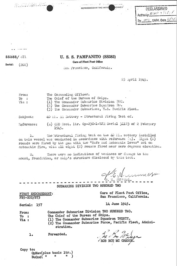
Testing of gun mount after change from single 20mm to single 40mm gun forward 25 April 1945.
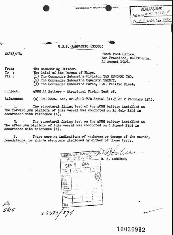
Testing of gun mount after change from single 20mm to single 40mm gun aft 14 July 1945.
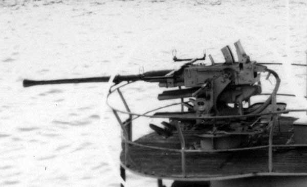
Aboard Pampanito 1945 aft.
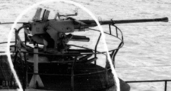
Aboard Pampanito 1945 forward.
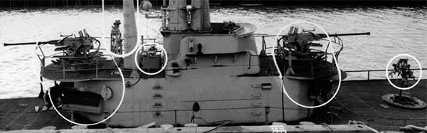
Aug 1945 showing two Bofors and the twin twenty forward.
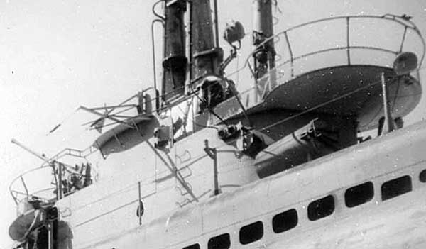
Pampanito Nov 1945 in Mare Island graving dock. Note the shell screen and barrel lock aft even though the gun is removed.
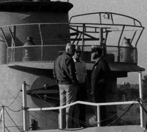
Late 1970s. Forward. Heading to Stockton before museum modification, after reserves. Note the shell screens, elevation deflection stop, 40mm gun foundation, and screw type muzzle lock.
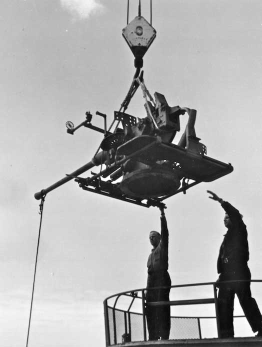
How to rig for loading the gun on another boat during WW II. NARA 80-G-468227
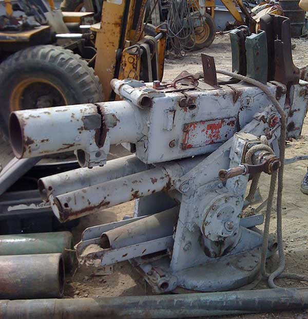
LA gun at recycle yard in San Pedro, CA.
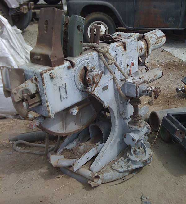
LA gun at recycle yard in San Pedro, CA.
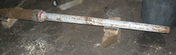
LA barrel as received.
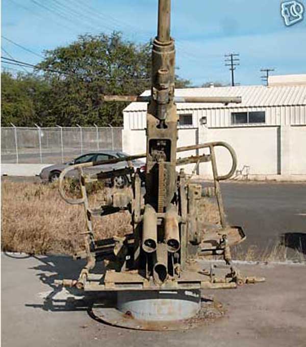
HI gun, photo from seller.
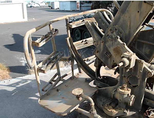
HI gun, photo from seller.
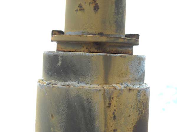
Typical welding of HI gun, barrel sleeve. Photo by Bowfin crew.
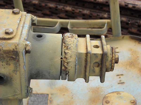
Typical welding of HI gun, hand operating sleeve. Photo by Bowfin crew.
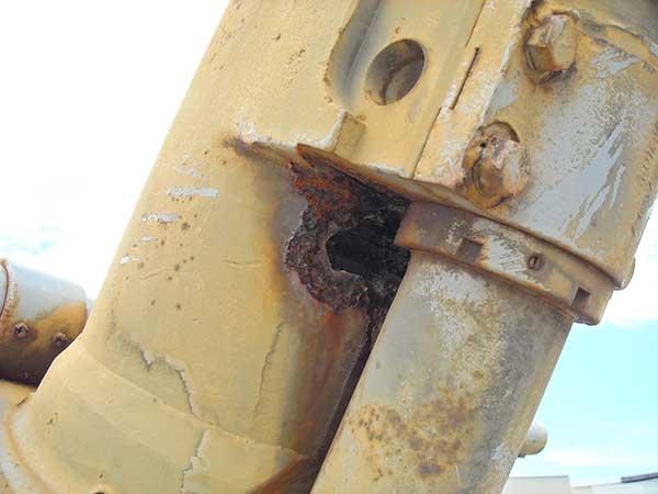
HI gun rotted out, the top of the recoil cylinder was also rotted. Photo by Bowfin crew.
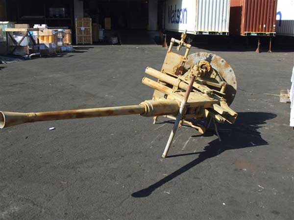
Gun in two pieces as picked up from airport in HI.
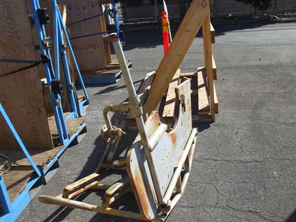
Gun in two pieces as picked up from airport in HI.
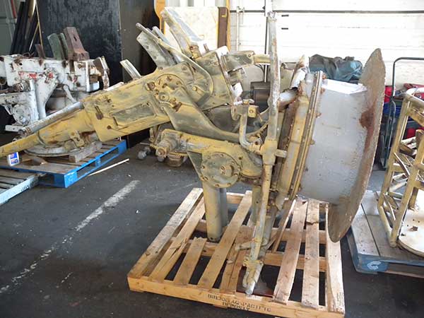
HI gun as delivered to Pampanito

Loader deck, magazine rack, from HI arrival condition.
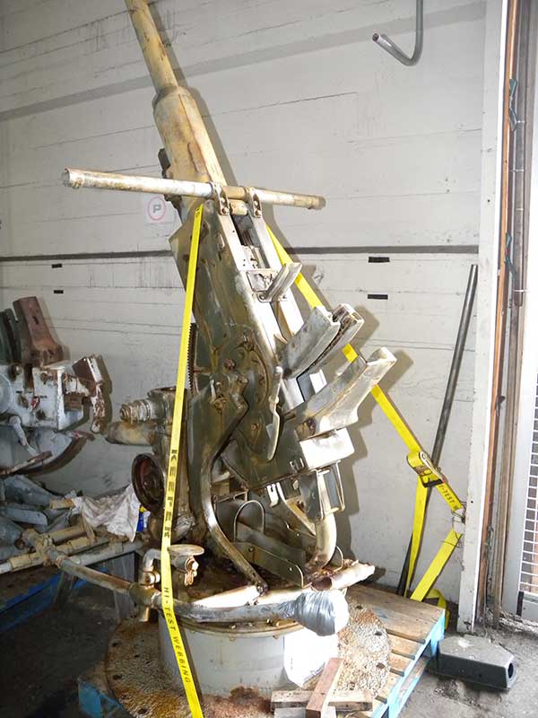
HI gun set upright. In seismically active San Francisco we needed to get this depressed or dismounted for safety.
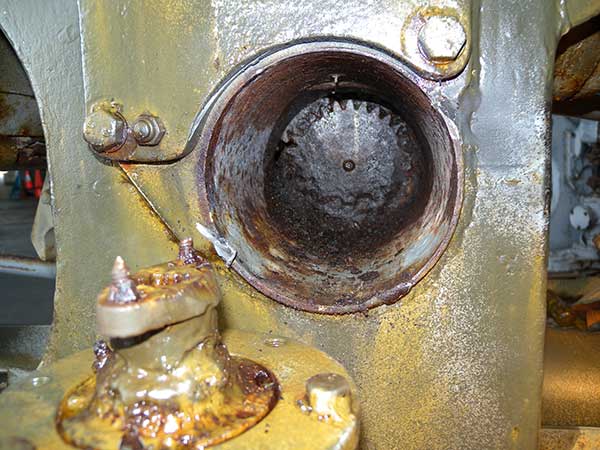
HI elevation gear was rotted out, we would not be able to depress the gun.
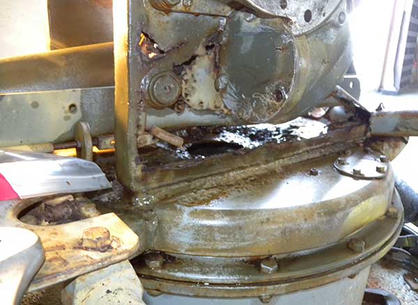
Another reason to dismount the gun, there was not enough metal in the mount to hold the weight.
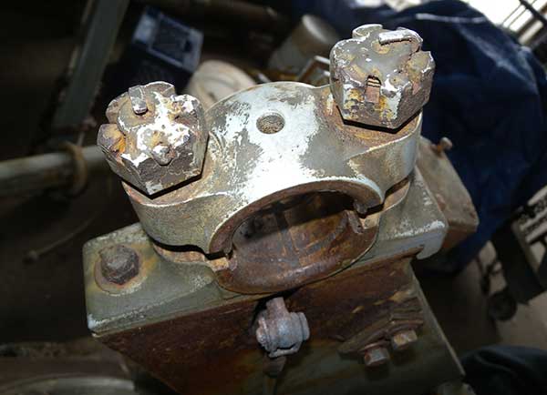
Trunnion cap studs unscrewed with the welded nuts attached. All the exposed nuts and bolts on this gun were welded.
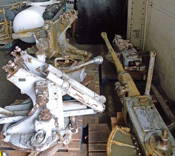
Both guns dismounted.
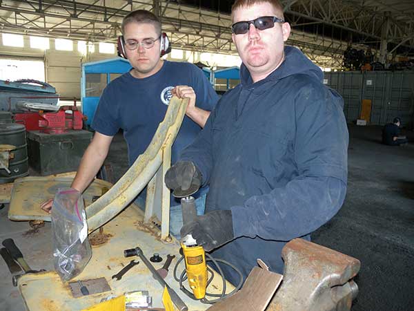
The US Coast Guard armory personnel came by for a day to help.
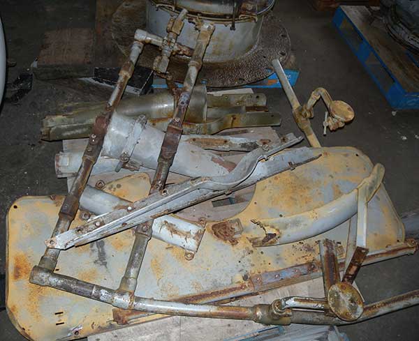
We got the remains of both loader decks and chutes off.
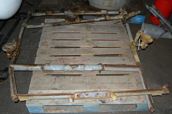
We laid out what we had to see what was missing from the loader deck frame.
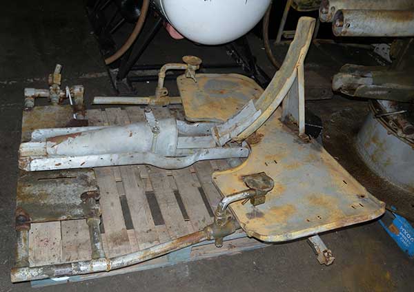
These are the recovered frame, deck and chute parts. Parts from both guns, it was not a complete set.
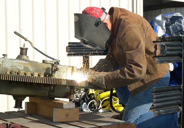
Ralph Waller used air-arc gauging to remove weldment.
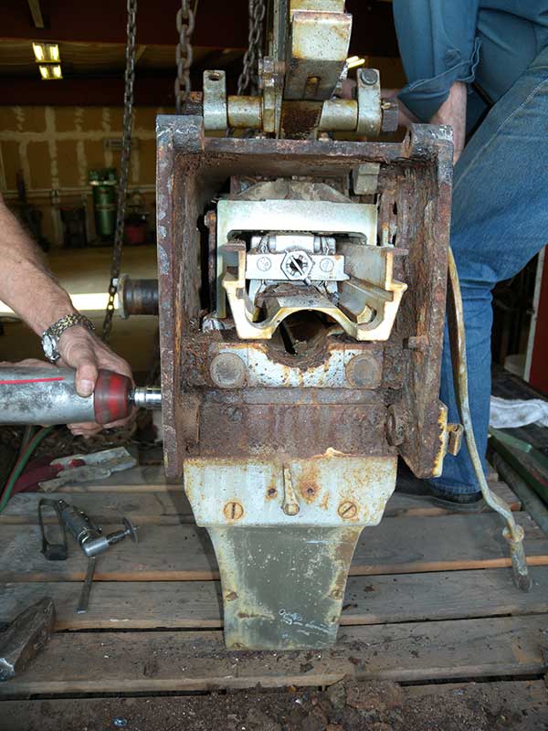
The center of the rear cover hinge was rotted away, the cover is off.
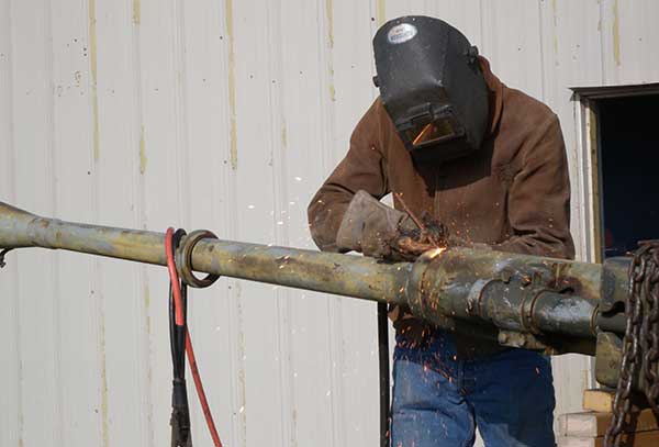
The bronze barrel sleeve was welded into the spring casing.
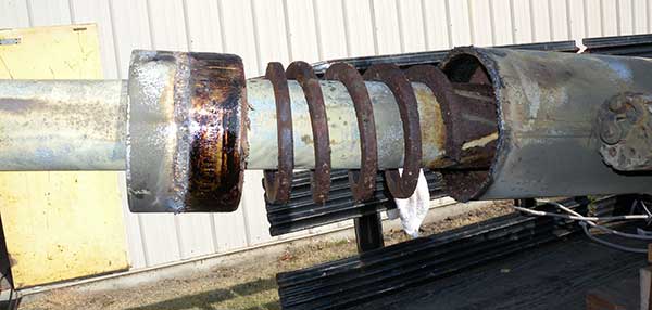
When the air-arc removed the weld 5 rings of the spring gently popped out.
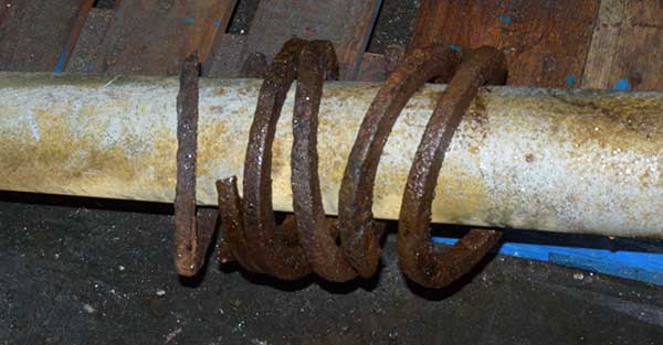
The next few rings came out one at a time. The deeper into spring casing we reached, the smaller the pieces that came out.
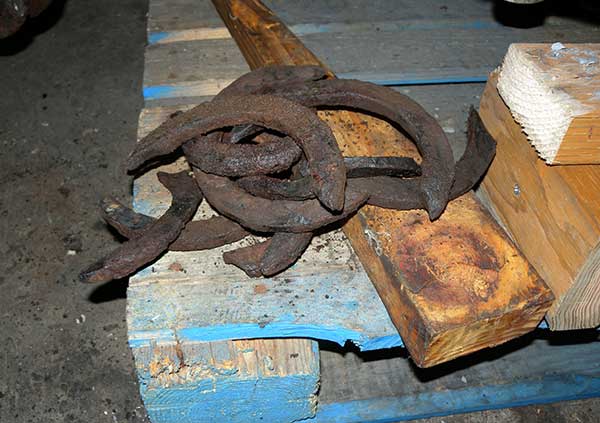
As the pieces got smaller, they were harder to get out.
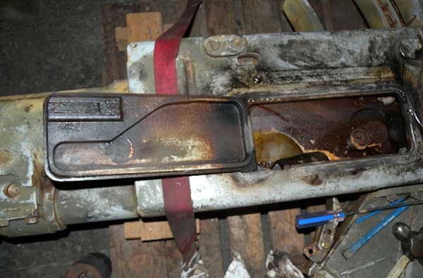
Getting the door open was difficult without breaking the latch parts.
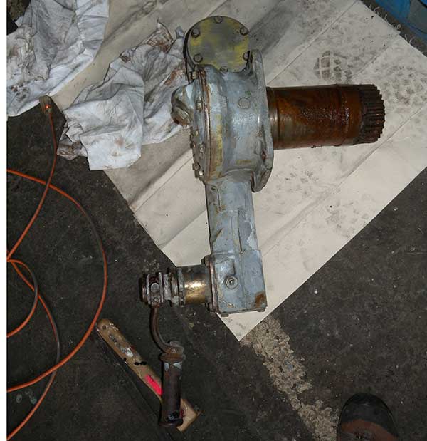
We got the elevating gear out of LA mount. It was frozen, we took it completely apart with Jake Roulstone's help.
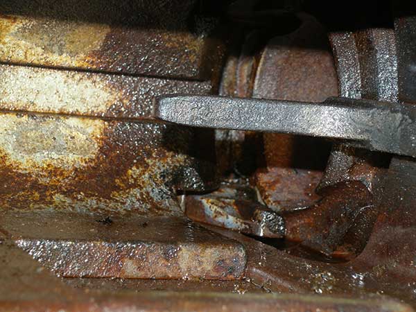
The breech is mid position, the extractors are jammed, the barrel is turned out of position.
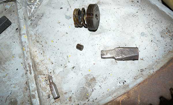
The loader bolt was frozen so the spring would not push it out. We removed the spring from the opposite side with customized tools. That allowed us push it out from the right side.
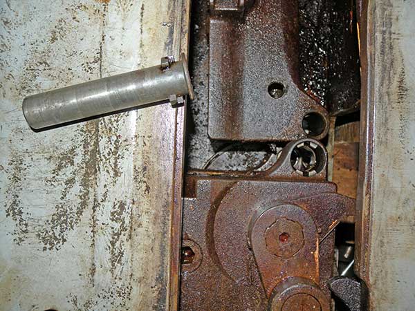
Loader bolt out, note the loader tray sprang out of position. It was under tension.
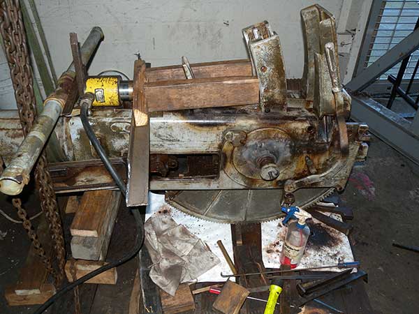
Loader moved. We tried a lot of less aggressive means to move this before the hydraulic ram. With the operating handle pulled partially back, its internal lever is preventing the loader from moving.
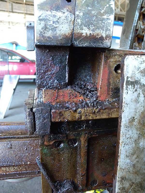
Every normally empty space was full of rust mixed with sand, and at the bottom, rocks.
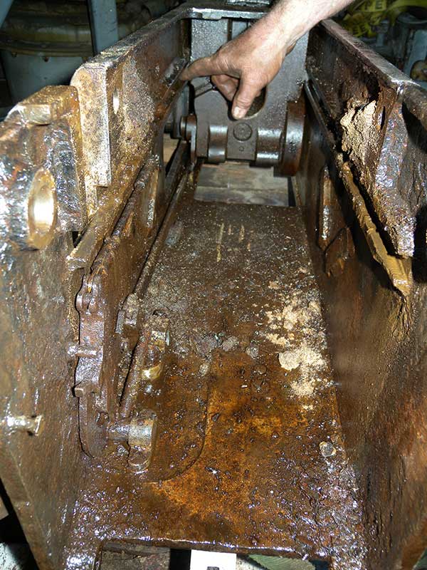
Another view of the sand/rust. There were rocks that prevented the hand operating lever from moving in addition to the rust.
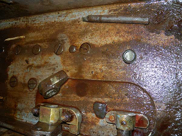
We broke the end of the hand operating shaft getting the loader out. Note the typical rock that might have been catching. The rod is what was left of the rear door hinge.
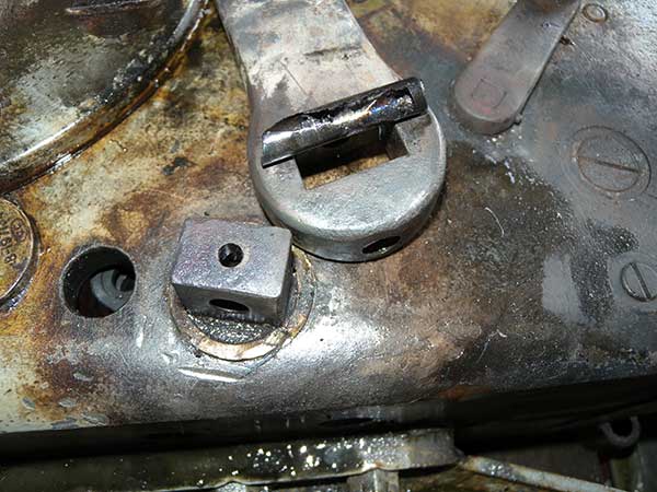
We had to drill out the hand lever pin. The shaft was still frozen. The bushing came out before the shaft turned.
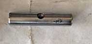
Replica hand operating lever hinge pin.
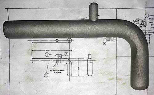
Replica breech locking bolt.
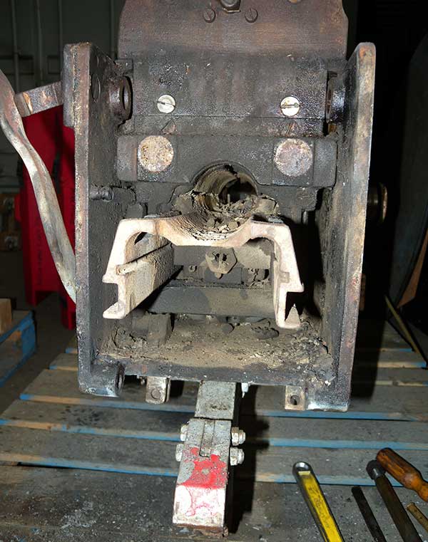
Animal remains in the LA gun.
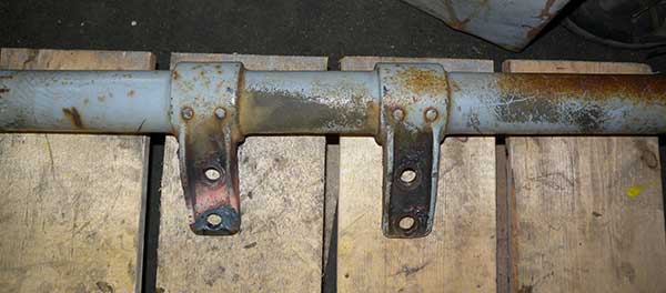
Repaired sight crossbar mounting flange after welding.
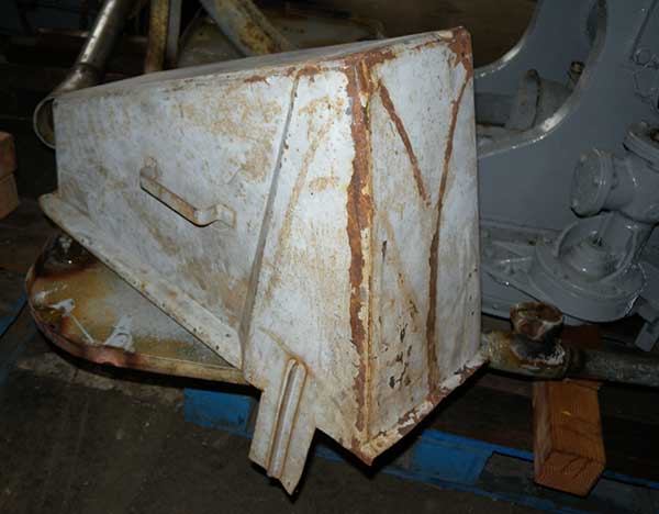
This loader cover was flattened when we found it. It is pretty close to original shape after some tender loving care with big hammers by Ralph Waller.
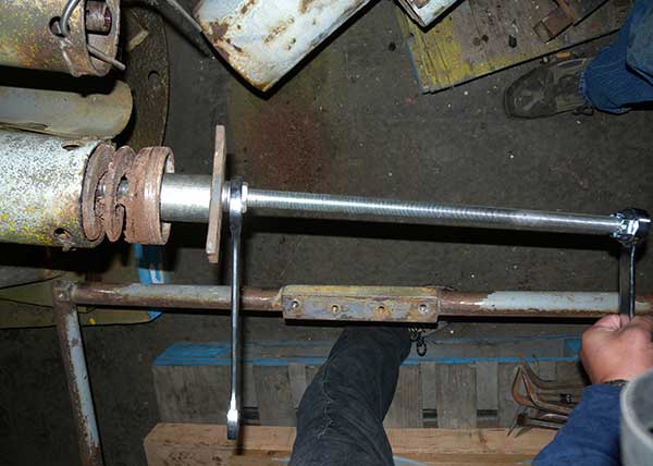
Our improvised tools used to relieve the spring tension on the equilibrator springs of the HI gun.
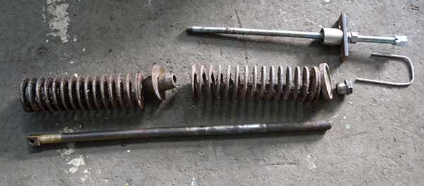
The two of the three removed springs, one of two separators, washer, nut, rod and our improvised tools.
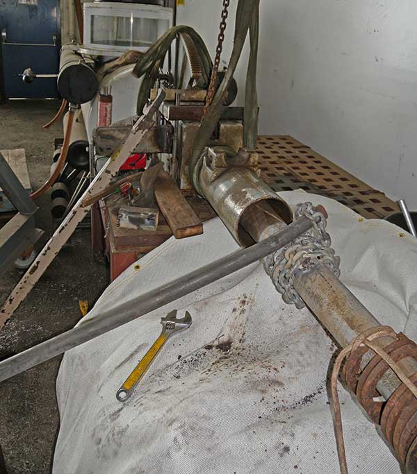
The final setup that got the barrel to turn. Nothing broke.
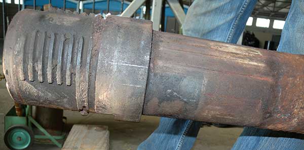
Once it turned a bit, it was only a matter of time before we got it out. The threads were full of rust and sand.
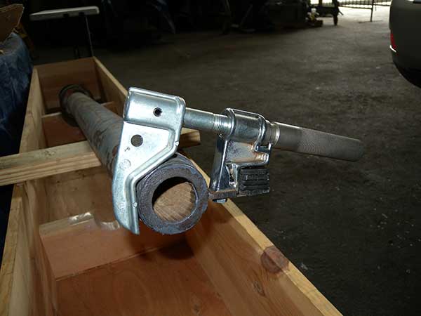
The threads on the LA barrel were rough. We started by using the OTC tool to repair the threads.
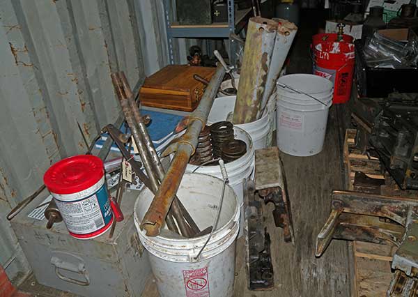
More and more removed parts in buckets.
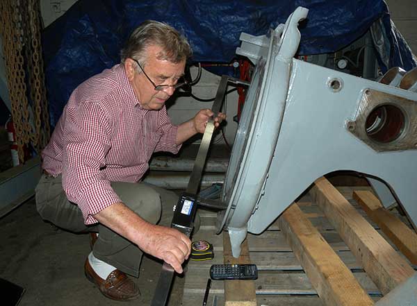
Measuring up the mounting holes for the foundation.
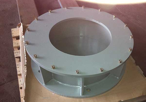
The replica foundation, copied from the original on the boat.
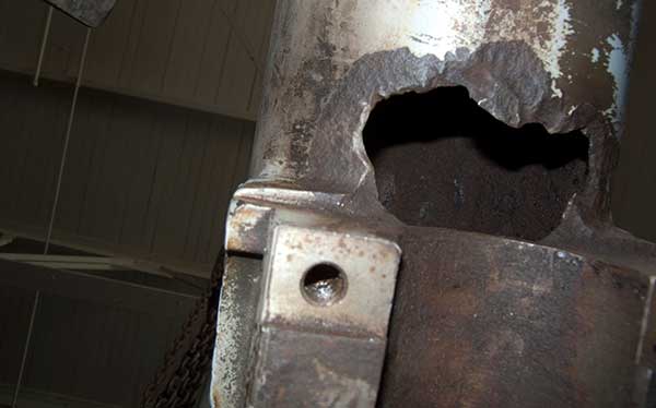
Spring casing rot before repair.
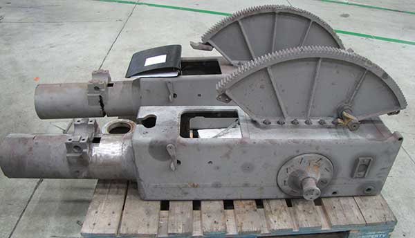
Breech casings after blasting and spring casing repair by NGMS.
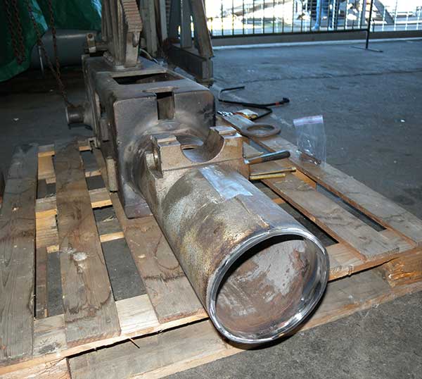
Spring casing after repair by Oakland Machine Works.
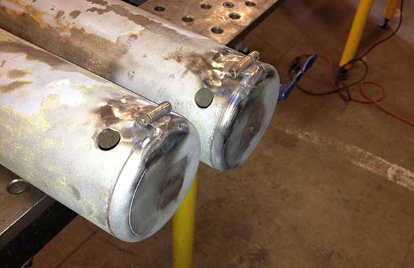
Equilibrator case replica covers created at Techshop by Pampanito volunteers.
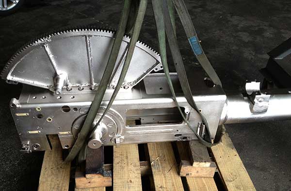
Breech casing and sector gear after plating by Electro-Coatings Inc.
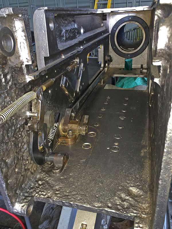
Inside breech casing. Firing mechanism, hand operating gear, stop pad and extractor lever installed.
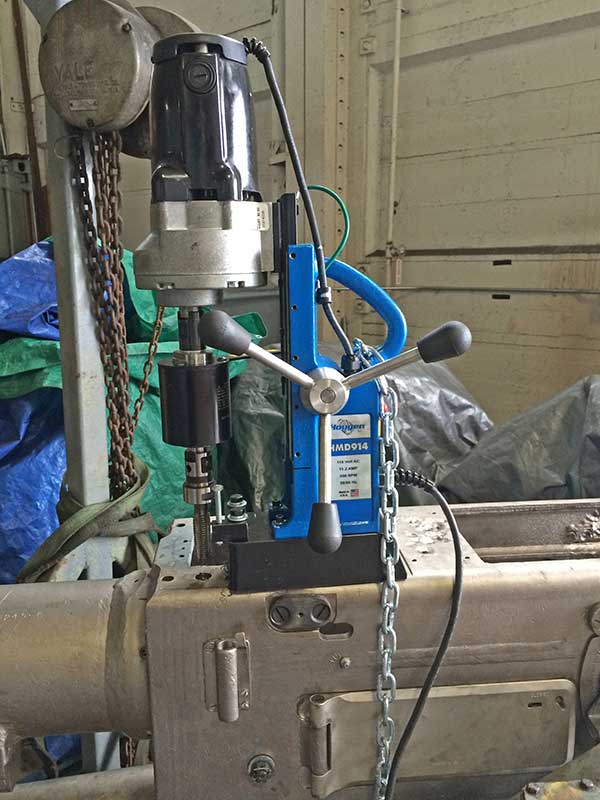
Drilling and taping new holes for thread inserts to mount sight cross bar. We only did two of the four but now wish we had done all four.
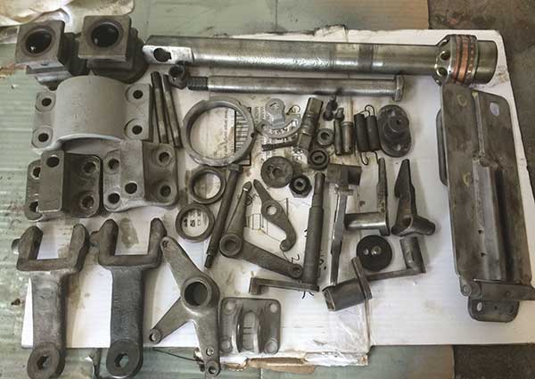
One of the batches of parts sent to plating. We plated parts that had been damaged by rust.
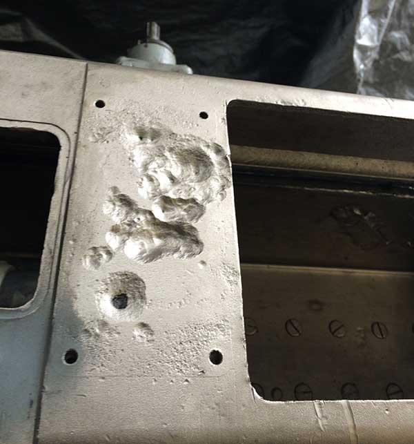
Pitting under the data plate before filling.
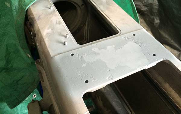
After filling. The data plate was bedded when installed. Also note the three pins restored, we are not sure what these are for. We guess a gunners quadrant. Two of the originals were broken off, they were extracted and replaced.
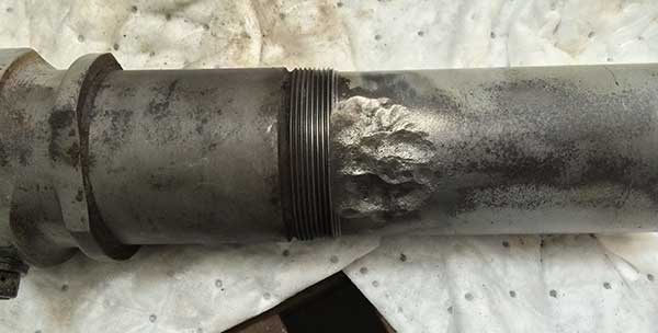
Recoil cylinder pitting.
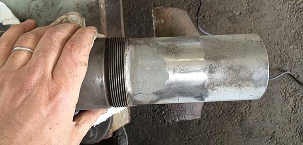
Recoil cylinder filled.
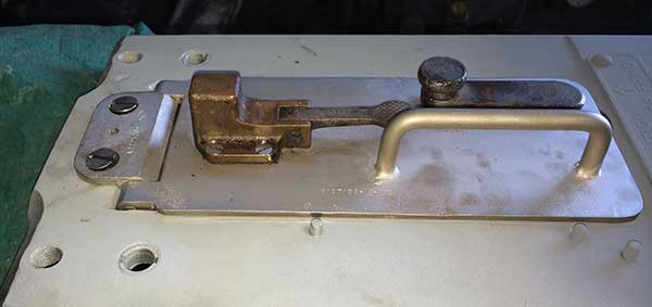
Restored top cover. The mounting screws are not straight and so the entire cover is about 1/16" to 1/8" too far forward. The repaired sight bar mounting holes are also visible.
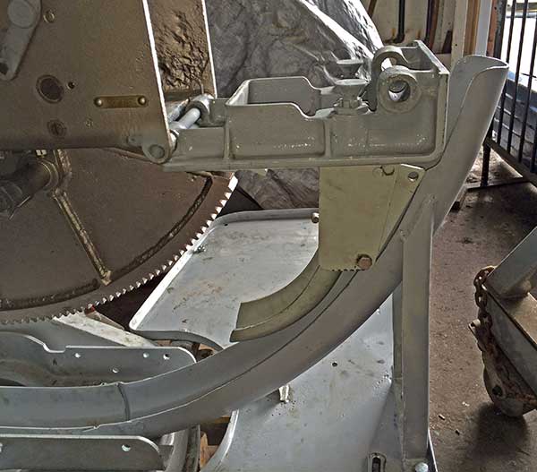
We did not understand the slots in the side of the rear chute until assembled and we opened the rear door.
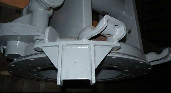
Training stop that was removed. It made the loader frame flange and bolts difficult to maintain and is not used on submarines. Submarines use extensions to the hand rails that block the barrel.
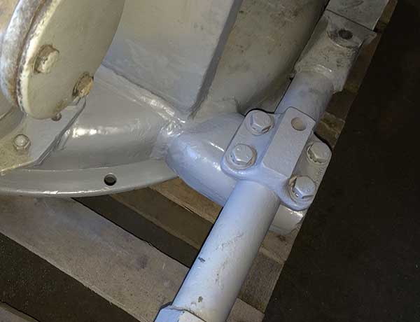
Training stop removed.
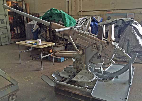
All the original parts were test fit Memorial Day 2014. It was still missing paint, handles, sights, and Army style seats. The high uncertainty work was completed.
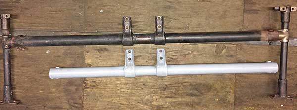
The sight crossbar, and sight parts on top (in black) are from VA gun. The grey sight crossbar on the bottom came on the gun from the HI gun. We extended the short side to make it symmetrical. When we stripped the paint, we found the same type of extension on the VA gun sight crossbar.
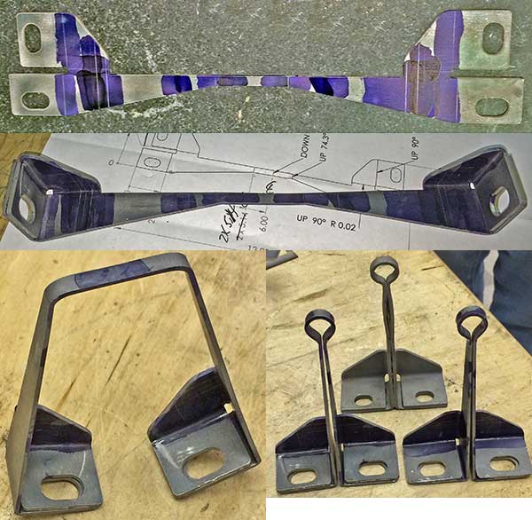
The Army style rear sights were bent from single pieces of sheet metal just like the originals. The two in front are replicas of the original in the rear.
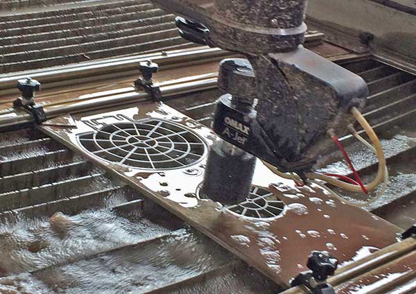
A computer controlled water jet of 55,000 psi water mixed with garnet was used to cut the replica Army style front sights. In this case we deviated from the original sheet metal construction.
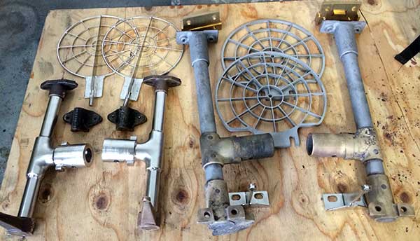
The sight parts on the left for the Navy style sights on the new gun, the parts on the right are for the Army style sights for the VA gun on loan from the Navy.
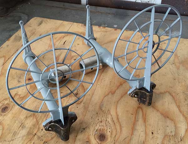
The Navy style sights ready for mounting and final paint. The welded sight bars, and one of the rear sights are replica. All the other parts are real.
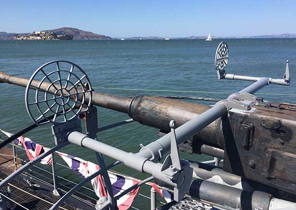
The Army style sights on VA gun. The front sights, front sight mounting adapter, and rear sights are replica. This rest is original.
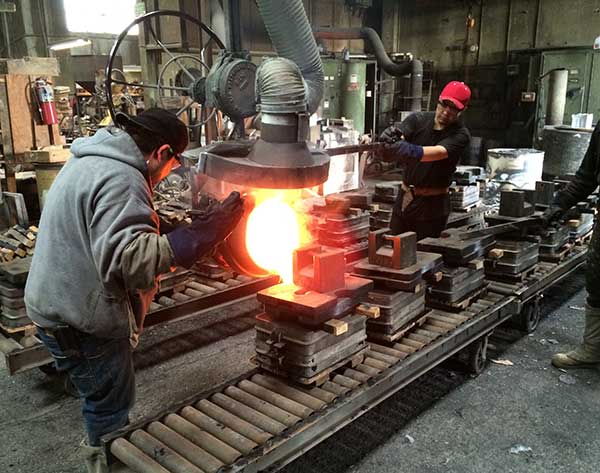
We borrowed real crank handles, and used a real Navy style rear sight as patterns for sand casting in bronze.
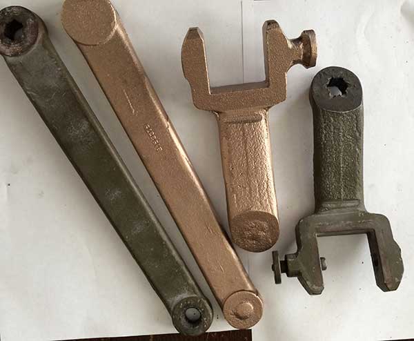
Original and replica castings. There is still a lot of work to machine the parallel surfaces, broach the splines, turn and mill the shafts, turn the plastic handles and create the locking shaft and handle.
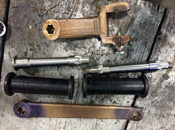
Machined crank handle parts before assembly.
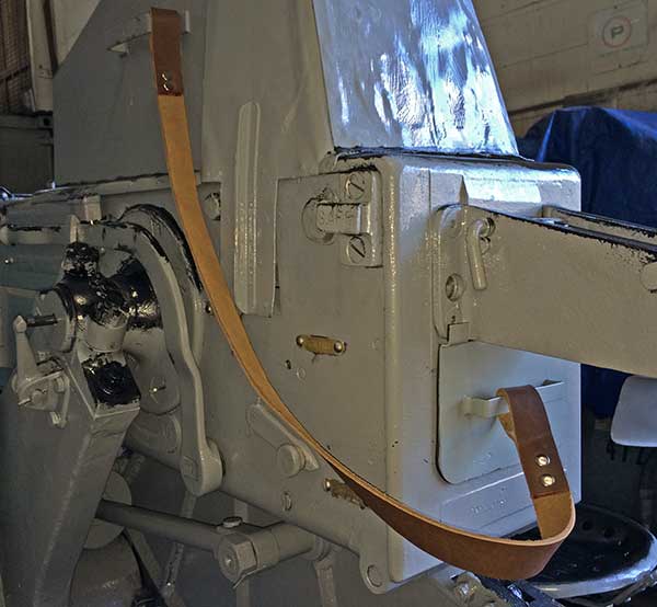
Real loader hood, replica rear shield with replica tie strap.
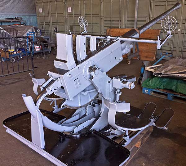
Painted with "distressed" Measure 32 using brush cross hatch and stippling on the grey to black transitions. The effect works from a distance, but is pretty crude up close. We are seeking the donation of spray tools for experimentation. 30 Aug 2014.
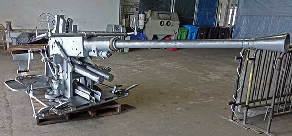
Another view 2016 with crank handles.
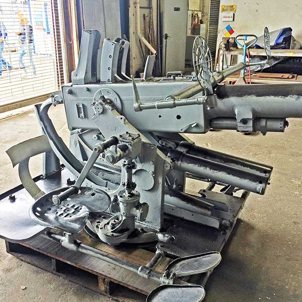
Another view 2016
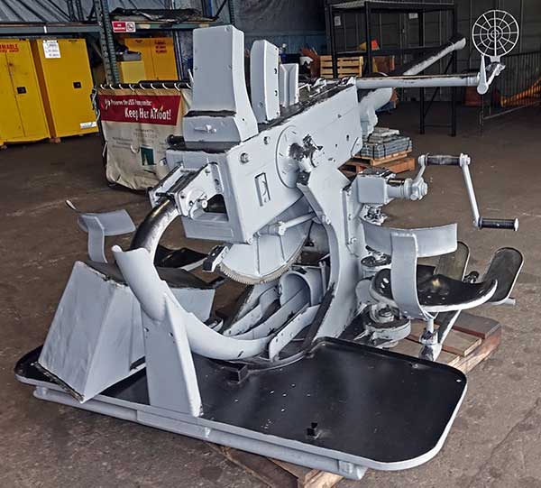
Another view 2016
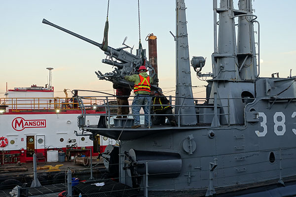
Nov 2016 the VA gun was removed for restoration before drydocking, the new fully restored gun (LA+HI) is shown being lowered onto the boat when Pampanito returned to Pier 45.
==== Below are a smaller sample of photos from the VA gun restoration ====
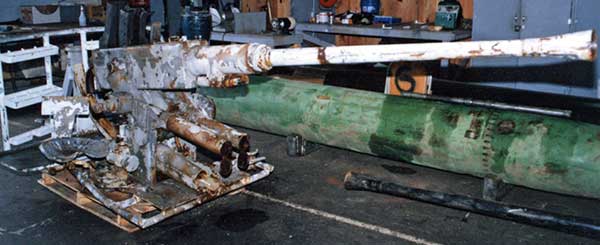
VA gun as received in the 1980s. Note the broken loader frame, no hand cranks, missing foot rests, no loader hood, and lots of rust.
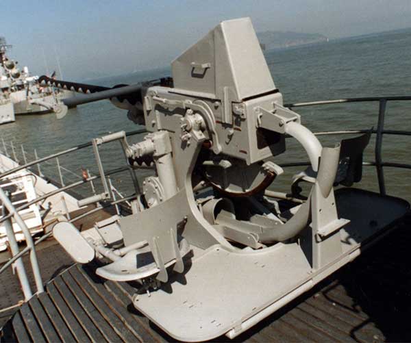
VA gun sometime after initial restoration in the 1980s. There are no front sights. Improvised hand cranks were installed.
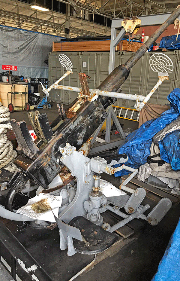
Nov 2018 VA gun in the shop near the start of the 2019 restoration. Front sights had already been repaired with replica parts. Heavy paint accumulation, and failed coatings.
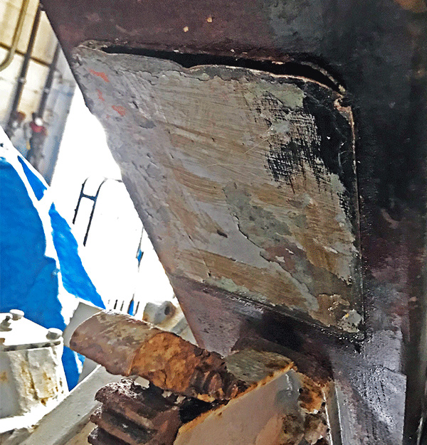
Mar 2019 VA gun sheet metal attached with non-historic screws instead of a bottom cover from the 1980s.
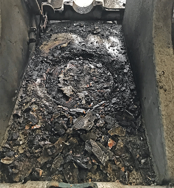
Mar 2019 VA gun some of the rust, putty, and crud that we chipped out above the cover that is hard to reach with the cartridge chute installed. We are still skeptical that the cover would have been installed on a submarine as it will hold air.
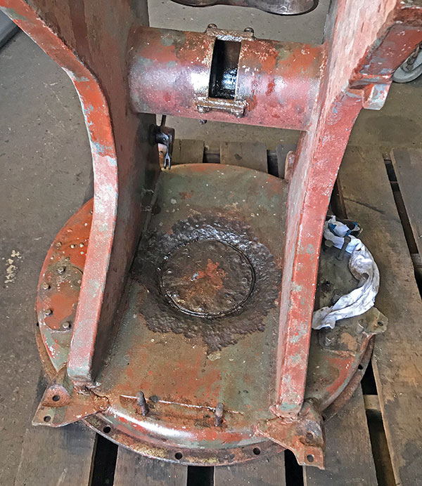
Apr 2019 VA carriage after the first pass of removing coatings. Note the red primer is not lead, we tested. There is deep pitting around the bottom cover. The heads of the screws are rotted away.
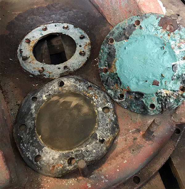
Apr 2019 VA carriage with rotted bottom cover and gasket.
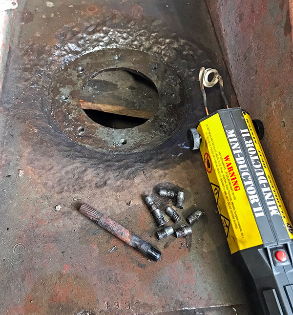
Apr 2019 VA carriage with last of the damaged screws removed. The induction heater worked really well on these.
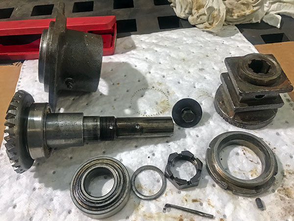
May 2019 VA elevating hand operating gear apart. Outer bearing is rusty inside. The traversing hand gear had similar damage.
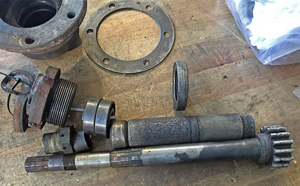
Apr 2019 VA gun. Traversing pinion shaft fully disassembled. All three bearings and both seals are damaged.
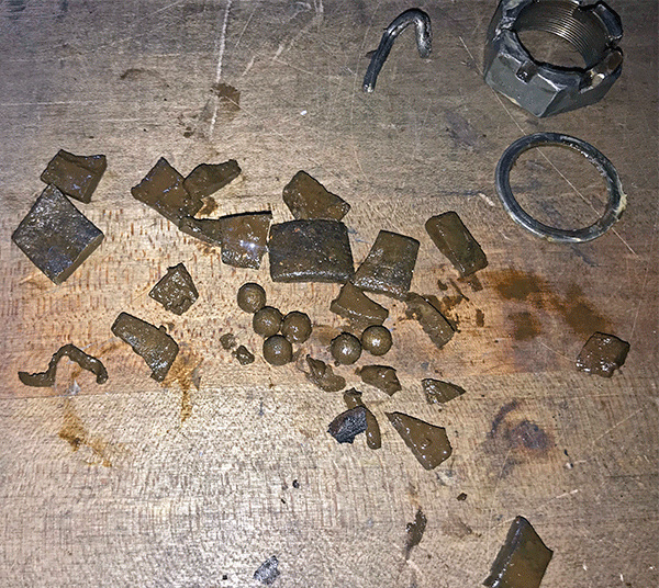
Apr 2019 VA gun. These ball bearings and pieces of the bearing outer race and cage found in the bottom of the traversing pinion case. They started in a bearing above the pinion gear and were forced through the pinion and spur gears below the bearing.
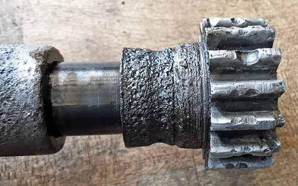
Apr 2019 VA gun. Traversing pinion shaft. On the left you see the spacer, then shaft, then the inner race of the lower bearing which is all that is left of the bearing. Finally the pinion gear with every tooth damaged by the pieces of the bearing as they worked their way past the gear.
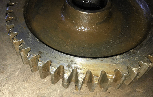
Apr 2019 VA gun. Damage to the traversing spur gear that meshes with the pinion gear above. This was later gently filed to remove high spots and gear re-installed.
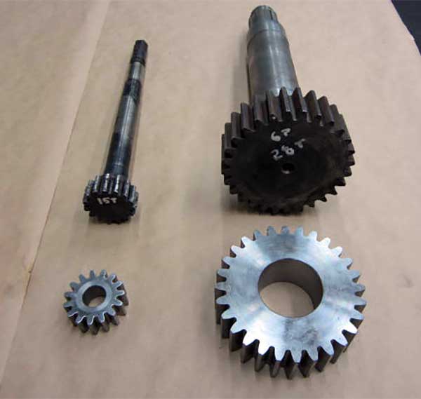
Nov 2019 VA gun. Custom Gear and Machine and Oakland Machine Works partnered to repair the traversing pinion and elevating pinion gears. First they were measured up, new "donut" blanks were made, then the gear cut on the blank.
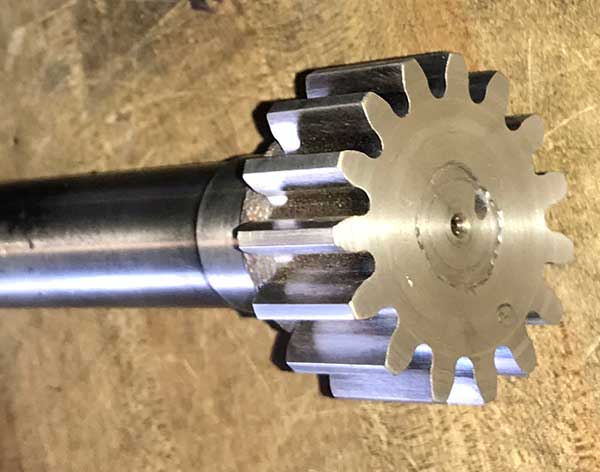
Nov 2019 VA gun. The old gear was then turned off the shaft, keyways cut in the gear and shaft, gear press fit to shaft, finally the gear welded to the shaft. This produced a really strong repair that preserved the maximum amount of historic fabric. The gear end was later nickel plated.
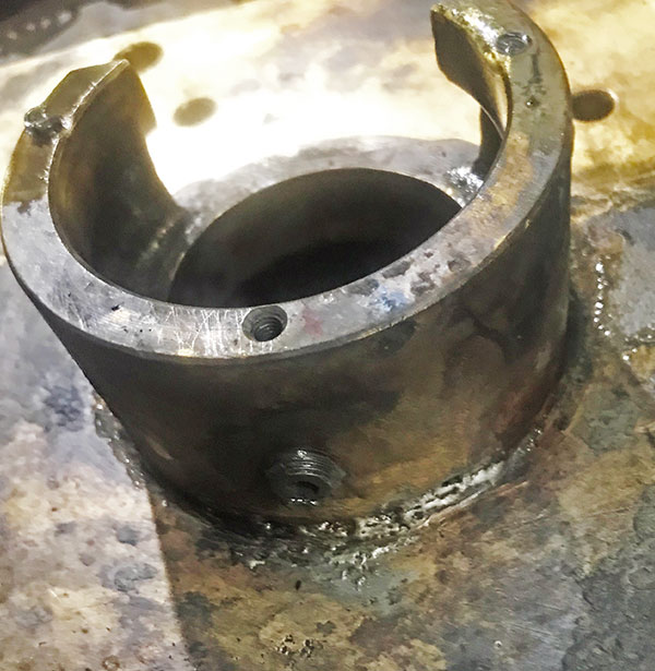
Apr 2019 VA gun. Traversing gear case has a poorly made solder repair. A damaged grease fitting was removed. The broken cover screws were extracted just after this photo was taken.
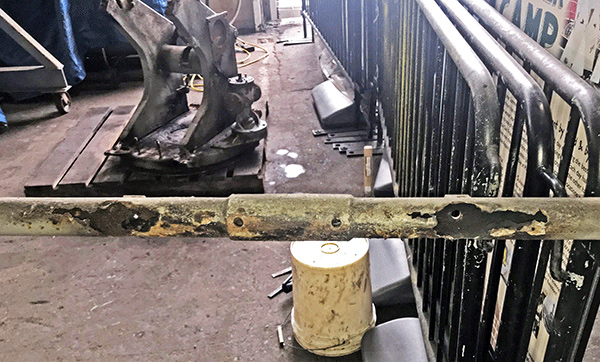
Apr 2019 VA gun loader frame is rusted out where it sat on the carriage.
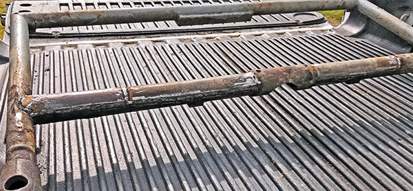
Apr 2019 VA gun loader frame with three half round insert repairs done by Ralph Waller. His careful work saved the maximum amount of the historic fabric.
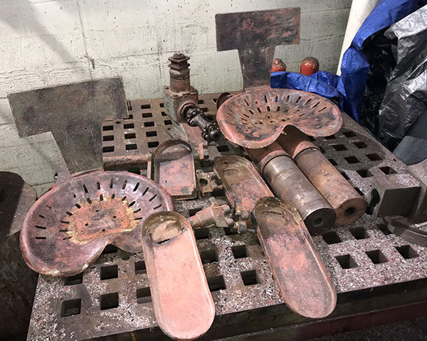
Apr 2019 After needle scaling to remove coatings from VA gun parts. It is not lead paint. You really never know what the metal condition is until the paint and rust are removed.
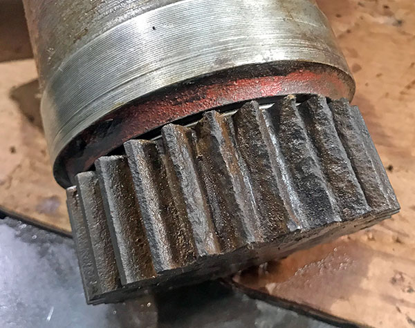
May 2019 VA gun elevating pinion was severely degraded by rust on 7 or 8 teeth.
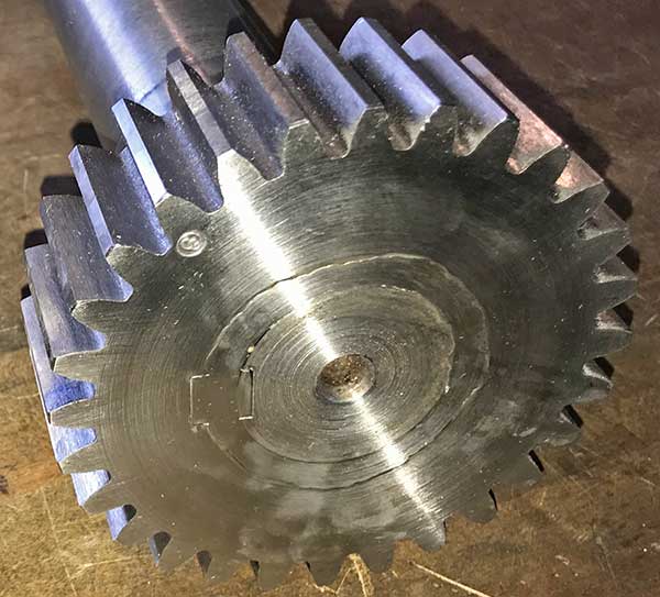
Nov 2019 VA gun elevating pinion gear repaired using the same technique as the training pinion gear described above.The gear end was nickel plated after this photo was taken.
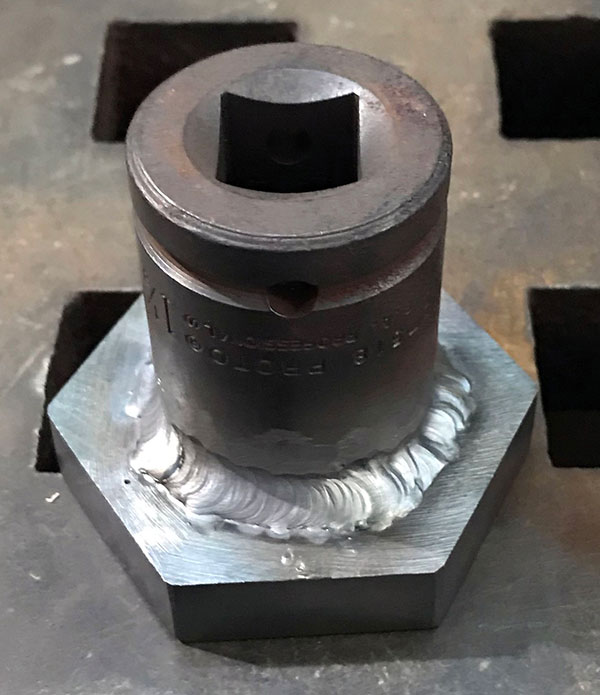
May 2019 We created a functional replica for wrench 41-W-1977-100 to remove the elevating pinion bearing cap A223889.
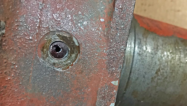
May 2019 The lock screw on the elevating pinion bearing cap was missing, and the hole drilled out.
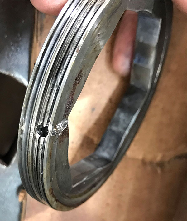
May 2019 The elevating pinion bearing cap had a hole drill through its threads and side. The detritus from this may explain why we stressed a 3/4" air wrench removing the bearing cap.
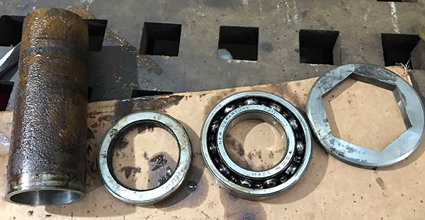
May 2019 Elevating pinion spacer, grease retainer, bearing, and bearing cap.
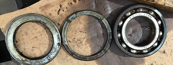
May 2019 Elevating pinion inboard grease retainer, spacer, and bearing.
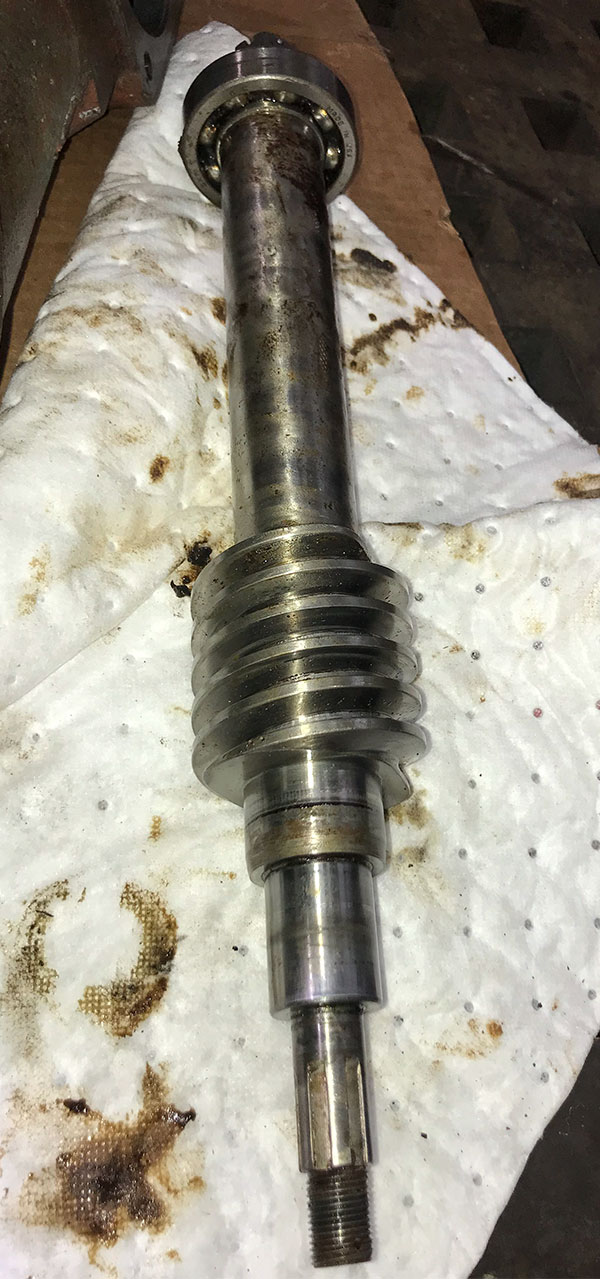
May 2019 Elevating worm out.
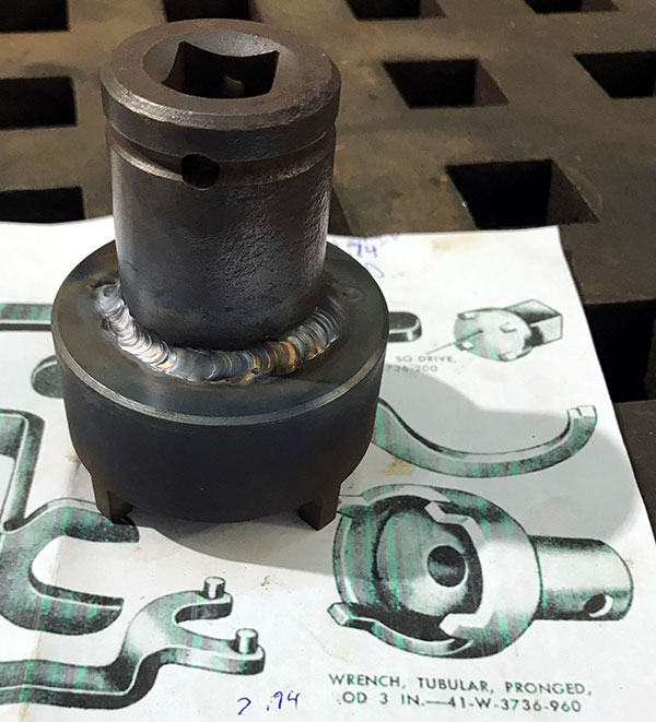
May 2019. We made this functional replica of wrench 41-W-3736-960 to remove the elevation worm pinion bearing cap, and the bearing cap of the traverse gear case. Note the elevating worm bearing cap that is removed after its shaft is removed, but training bearing cap normally has the shaft installed before the bearing cap is installed. Also note the deep fingers to reach over the casting by way of the grease fitting hole in the transverse cap.
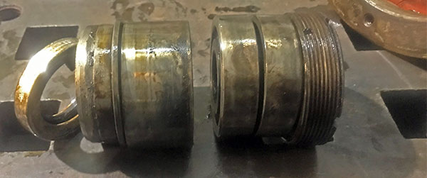
May 2019. Removed elevation worm pinion bearing cap, two bearings, bushing, sleeve and grease retainer.
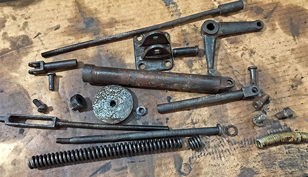
May 2019 VA gun external firing mechanism apart.
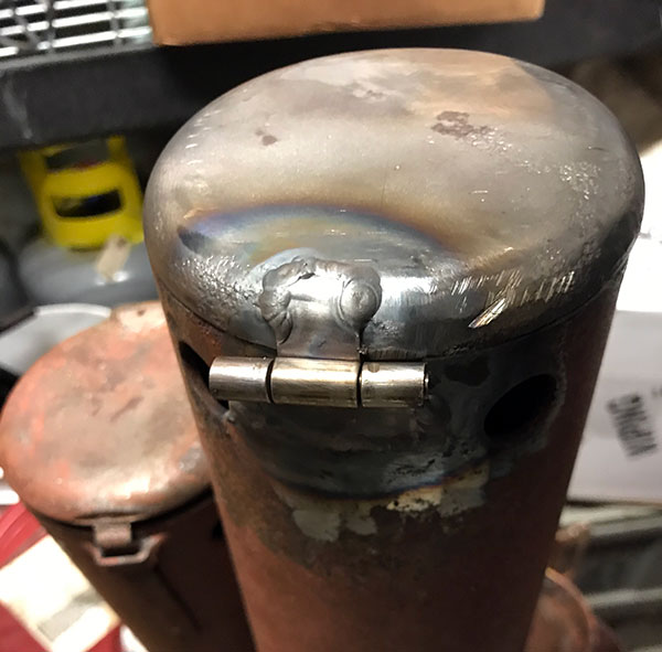
May 2019 VA gun equilibrator with replica hinge, and a real cover from another WW II gun.
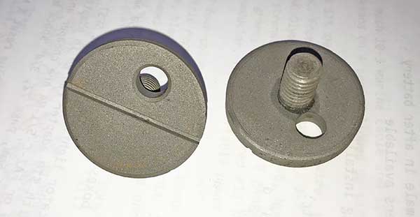
Jun 2019 VA gun replica gear screws A223966 for hand operating sleeves.
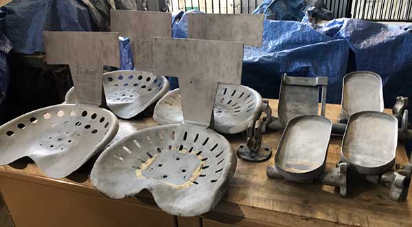
Jun 2019 VA gun. The two seats on the left are replicas of the Army style seats created by Ralph Waller that will be used on the HI+VA gun to replace the Navy style seats initially installed. The next two seats are the ones we found on the VA gun. They show signs of multiple repairs in the past. The foot pedals on the right were repaired with small steel inserts.
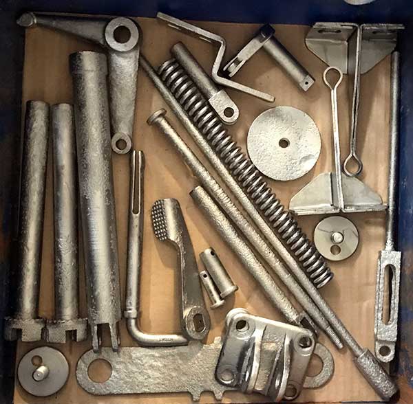
Jan 2020 VA gun. Small parts nickle plated for VA gun. ECI also nickle plated the seats, seat bases, seat posts, seat handles, and replica end of traverse and elevating pinion gears.
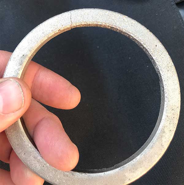
Feb 2020 VA gun. The elevating pinion spacer has a crack in it, but is stable.
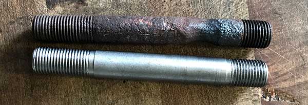
Feb 2020 VA gun. Original and replica stud for rear of loader deck.
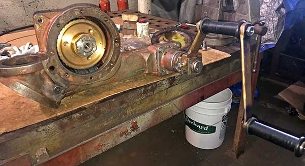
Feb 2020 VA gun. The elevating pinion case re-assembled and tested on the bench. We replaced 3 seals, 3 bearings, all the lock washers and cotter pins. The crank handle assembly and sleeve screw are replicas we made. The covers were waiting for new gaskets.
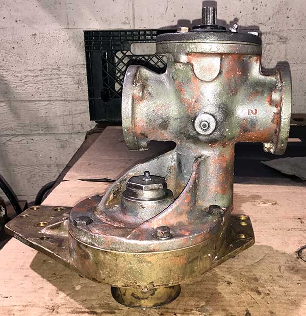
Feb 2020 VA gun. Training pinion with repaired pinion gear, two new seals, four new bearings, all new lock washers and cotter pins. The side covers were waiting for new gaskets.
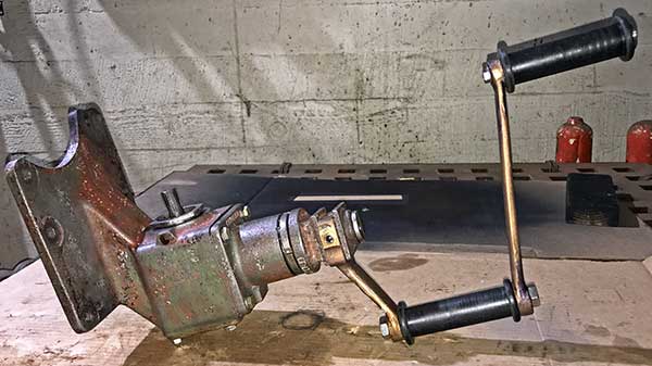
Feb 2020 VA gun. Training hand gear with three new bearings, and replica hand crank assembly and sleeve screw.
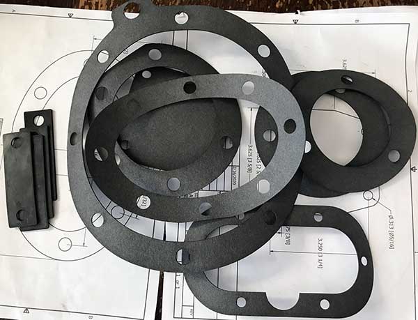
Feb 2020 VA gun. We used one of the CNC laser cutters at humanmade.org to create the gaskets. We also laser cut rubber elevation sector stops from n-buna rubber.
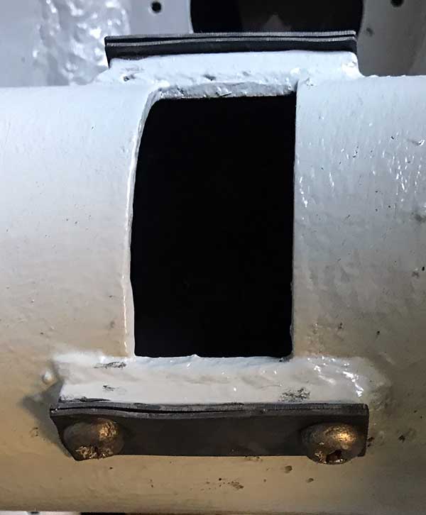
Feb 2020 VA gun. Tube pads, elevation sector stops installed. The originals were probably leather, but leather does not survive in our environment.
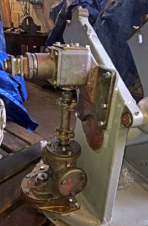
Feb 2020 VA gun. Overhauled training gear re-installed. Most of the backlash is in the splines of the flexible coupling. The threaded taper pins were installed after this photo.
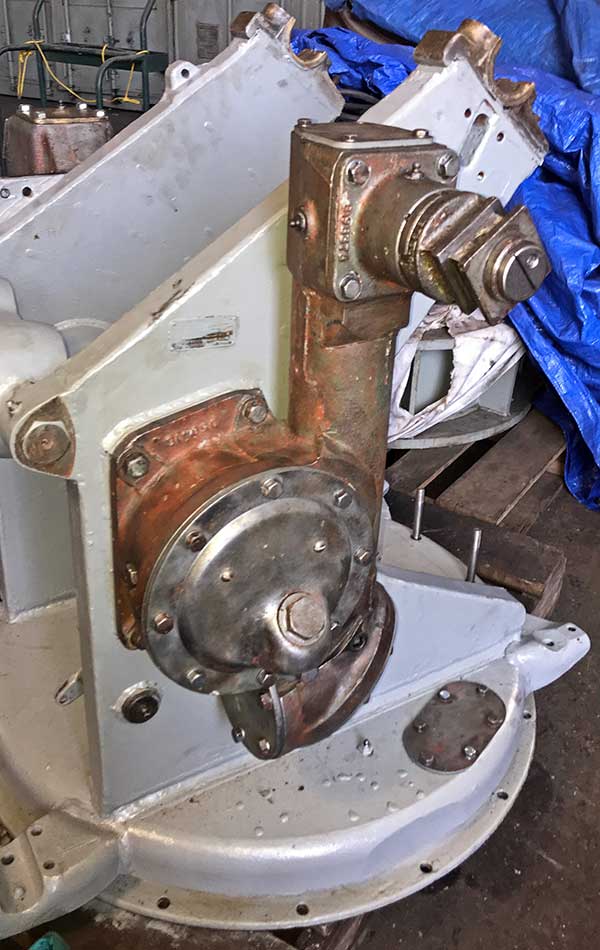
Feb 2020 VA gun. Overhauled elevating pinion re-installed.
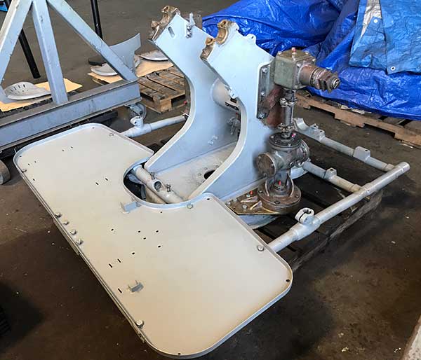
Feb 2020 VA gun. Loader frame and deck installed. Elevation pointer installed.
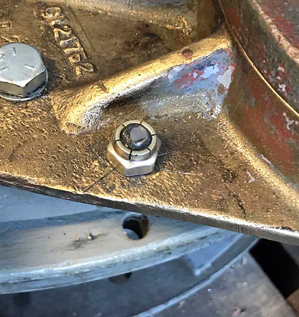
Mar 2020. To remove a threaded taper pin, tighten (clockwise) turn the flex lock nut. It will pull the threaded taper pin out of its blind hole.
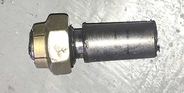
Mar 2020. Another view of the threaded taper pin with lock nut.
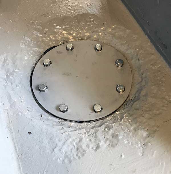
Mar 2020. Replica bottom cover rubber gasket and mild steel cover installed.
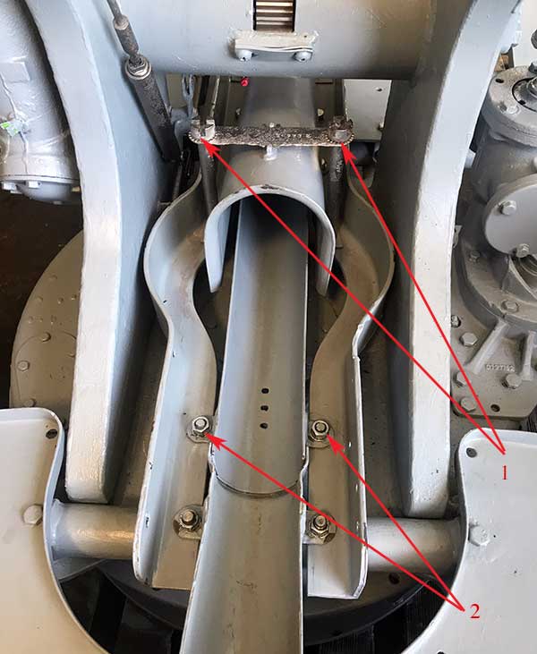
Jul 2020. To access the bottom cover for painting: 1-Remove the chute stud cover and studs. Slide the chute aft to remove. 2- Remove two nuts and then lift and withdraw the rear, intermediate cartridge chute. This can be done with everything else in place.
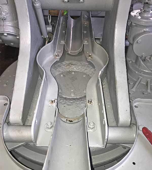
Aug 2020. Access for maintenance with minimal removals.
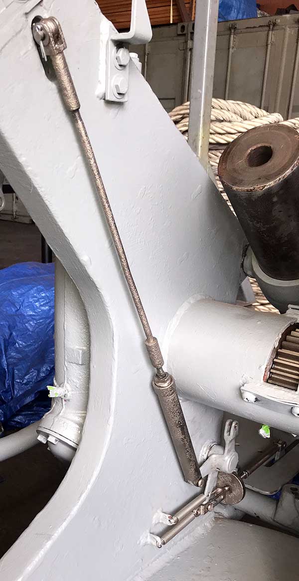
Jun 2020. External firing mechanism installed.
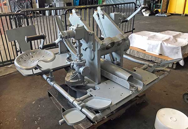
Jul 2020. Shell ejector chute and seats installed.
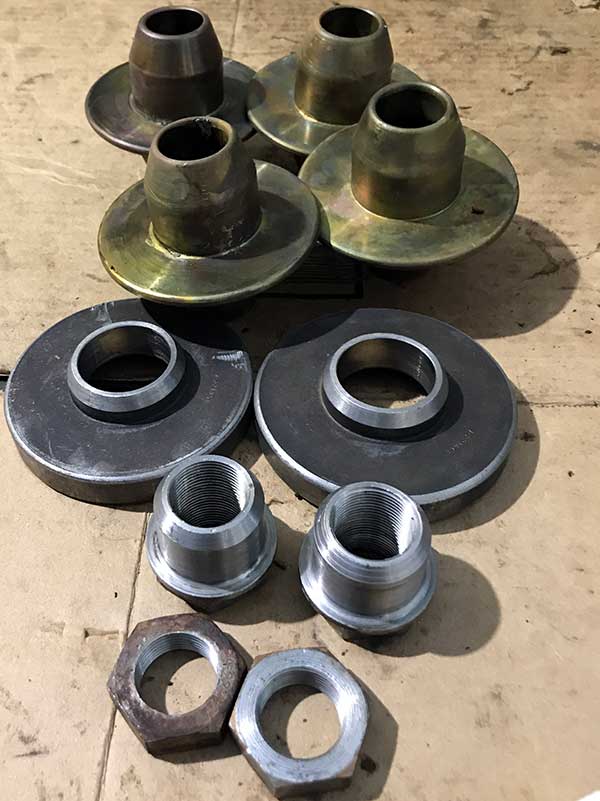
Mar 2020. Equilibrator spring spacers and nuts were in good condition after cleaning. The rods had more rust damage and were nickle plated.
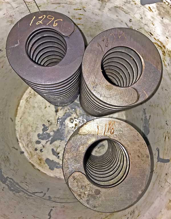
Mar 2020. The ends of the equilibrator springs were etched with spring force. There are two right and one left (center) springs. Across the two spring casings, the three springs in each case were chosen to have a similar total force.
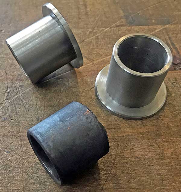
Jun 2020. Replica equilibrator bushings on top. The originals had the flange broken off.
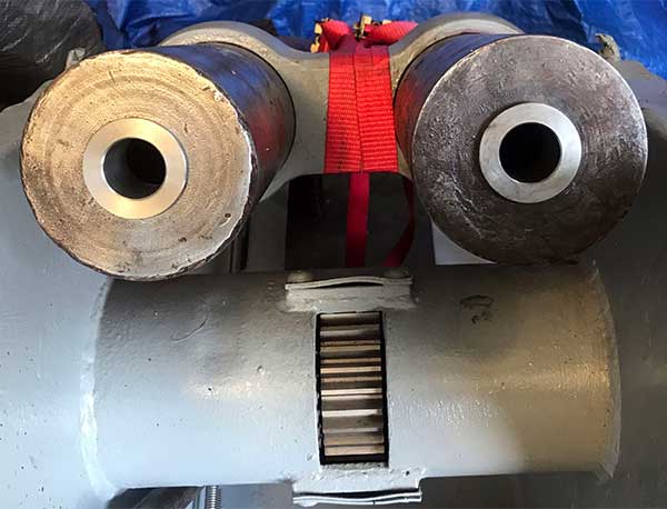
Jun 2020. Replica equilibrator bushings installed in the cases.
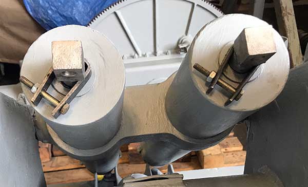
Aug 2020. The ends of the equilibrator spring rods are held 3/4" from the end of the spring casing by temporary holders at the start of spring installation.
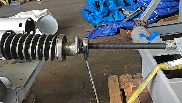
Aug 2020. The springs are loaded right, left, right turn with separators in between. The spring compressor rod is screwed into the end of the equilibrator rod. This photo shows the spring before tightening.
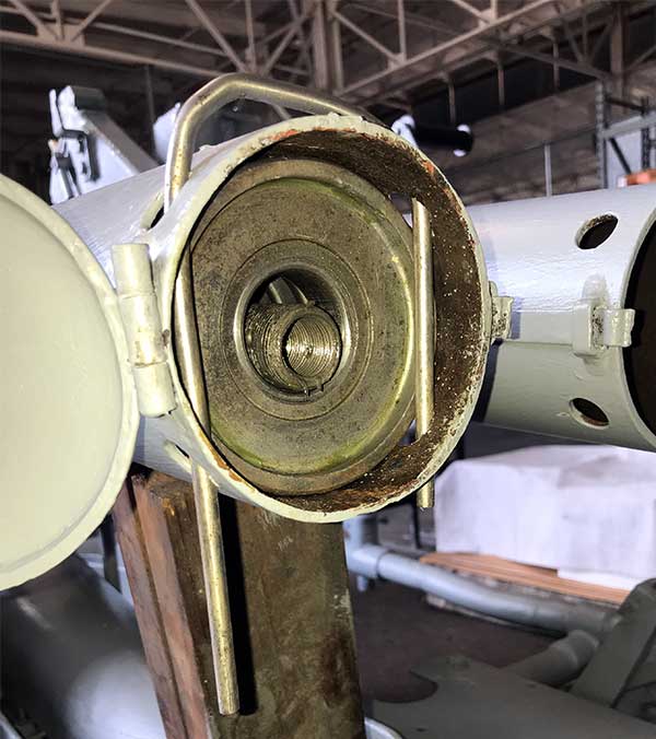
Aug 2020. The spring is compressed, then the holder (the bend rod) is installed, then the compressor backed off. The pressure of the springs is now on the holder. The compressor rod is removed, and we are now ready to screw in the nuts.
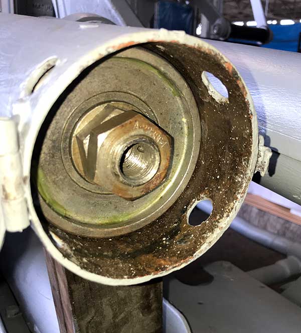
Aug 2020. The spring nut is tightened relieving the pressure on the holder which is removed. The depth will be evenly adjusted for equal elevation/depression after the gun is fully installed.
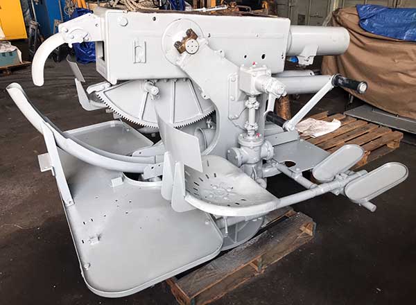
Aug 2020. Breech casing re-mount on carriage.
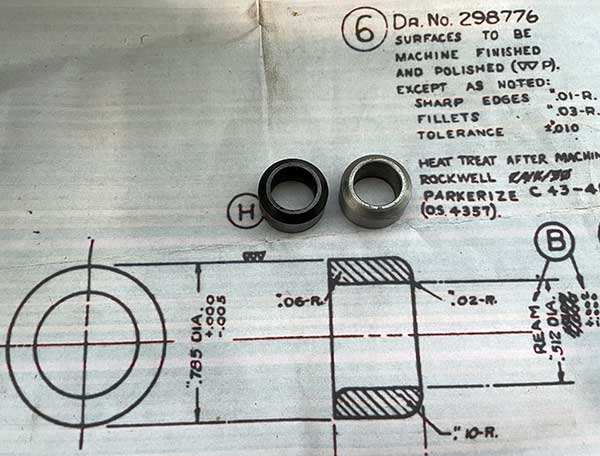
Apr 2021. Original loader tray roller on the left, replica on the right.
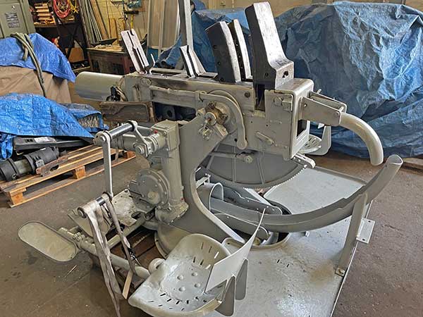
Apr 2021. 20 Apr 2021 Pampanito went to drydock on short notice. So after Covid-19 and Pier 45 fire and mooring failure crises paused restoration we needed to re-assemble as quickly as possible so the gun could be mounted during the crane availability in drydock. Cleaned and lubricated breech ring and loader are re-installed. The equilibrator rods are attached to the breech casing without the barrel installed so there is a strong spring force trying to elevate the gun. We have straps on the elevation handle and on the muzzle end of the breech casing for safety.
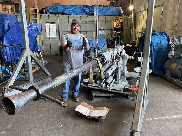
May 2021. Barrel starts upside down, then turns 180 degrees once in the interrupted threads of the breech ring. We used the chain hoist on our gantry crane to hold the weight, it makes installation really easy. Breech was also re-installed.
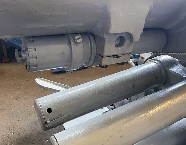
May 2021. Recoil buffer re-installed. We did not disassemble and overhaul it, just exterior coatings.
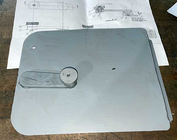
May 2021. Replica bottom cover for VA gun, prepped for coating.
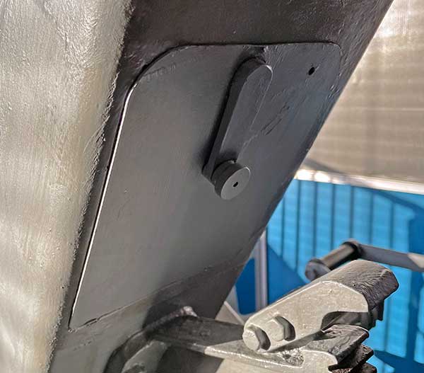
May 2021. Replica cover installed.
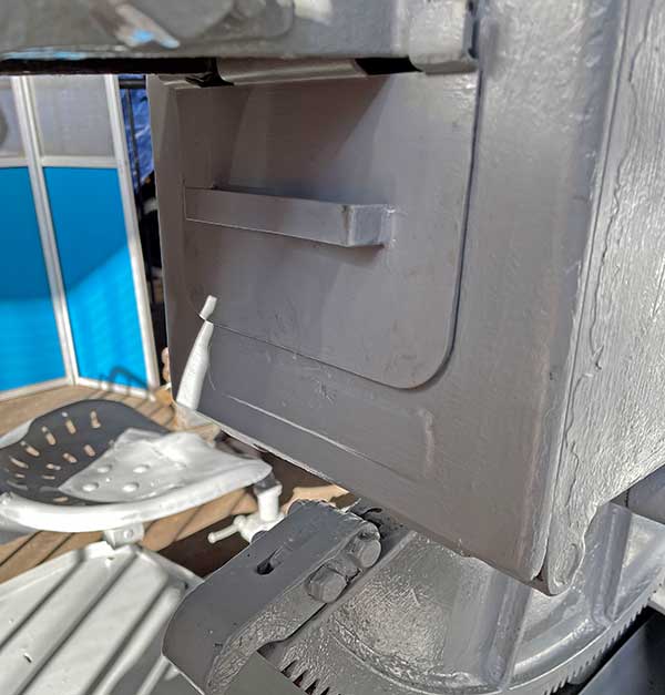
May 2021. Replica rear cover installed. This is too tight and needs to be reworked to fit properly.
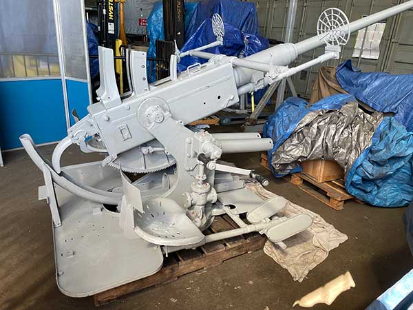
May 2021. Reassembled VA gun, complete with two coats of epoxy primer. All but the loader cover that is waiting restoration installed.
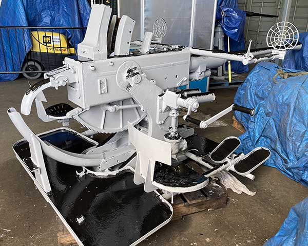
May 2021. VA gun with two coats of polyurethane top coat, and Measure 32 camouflage ready for mounting on the boat. The black from above better hides the boat from aircraft when dived. The black is roughly applied to avoid sharp lines and to invoke the war time shipboard painting.
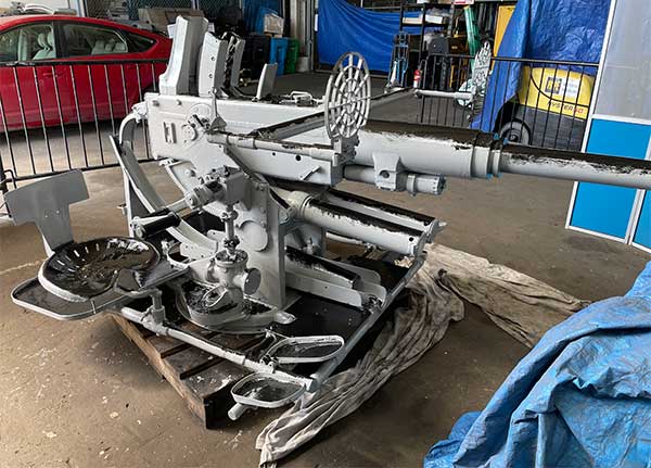
May 2021. Another view fo VA gun with Measure 32 camouflage.
Jun 2021. Gun is lifted over the DD-1 drydock wing wall at Bay Ship and Yacht on the way to Pampanito. Note the correct pick points.

June 2021. Muzzle locks and shell screens are still needed forward and aft. Forward gun needs the deflection stop on the rail.
VIDEOS:
Each of the videos in the links below have glimpses of Bofors guns on Fleet submarines. We could not afford to buy reference copies, but the still clips on the vendor's website were helpful:
• http://www.criticalpast.com/video/65675076062_USS-Skate_submarine-underway_sailors-working_water-breaking-over-surface
• http://www.criticalpast.com/video/65675075999_United-States-sailors_submarine-underway_firing-gun_men-aboard-junk
• http://www.criticalpast.com/video/65675075187_USS-Bluegill-SS-242_World-War-II_firing-rifles_Chief-Petty-Officer
• http://www.criticalpast.com/video/65675075917_USS-Trepang_enemy-sampan-underway_shells-being-fired_man-standing-on-deck
• http://www.criticalpast.com/video/65675076075_American-submarine_bow-of-submarine_Japanese-motor-sampan_firing-deck-gun
• http://www.criticalpast.com/video/65675075959_United-States-officers_Suma-harbor_officers-discussing_submarine-commander-being-congratulated
• http://www.criticalpast.com/video/65675052641_United-States-sailors_firing-5-inch-gun_aboard-submarine_sun-set_firing-shoreline
• http://www.criticalpast.com/video/65675076080_American-submarine_loading-torpedo_men-standing_clearing-search-light
• http://www.criticalpast.com/video/65675052646_Commander-George-L-Street-III_USS-Tirante-SS-420-submarine_Japanese-junk-set-on-fire_periscope
• http://www.criticalpast.com/video/65675076031_United-States-submarine_men-on-deck_5-inches-gun_watching-through-binoculars
• http://www.criticalpast.com/video/65675076094_American-submarine_submarine-underway_bow-of-submarine_airplane-in-flight
• http://www.criticalpast.com/video/65675075978_United-States-submarine_airplane-in-flight_watching-through-binoculars_men-aboard-tender
These show manufacturing during WW II.
• http://youtu.be/EF95yXtPcEQ
• http://youtu.be/u8ryXclE2Ww
| 