PLATE XX
DETAILS OF OBRY GEAR.

A frame.
B valve-body.
D air-cushion cylinder.
E frame-lugs.
F gyroscope wheel.
G inner ring.
H outer ring.
I impulse-sector.
M boss.
O stop-arm.
V vertical rock-shaft.
W centering-arm.
X boss arm.
Y rock-shaft spring.
Z counter-weight.
a control-pin.
b valve-arm.
c valve-plug.
dd valve-plug adjusting-screws.
ee valve-plug springs.
g valve guard.
h air-pipe to valve.
j steering-rod coupling.
ll frame pivot clamping-screws.
nn outer-ring pivots.
oooo outer-ring clamping-screws.
v counter-weight jamb-nut.
plate20
 

PLATE XXI.
DETAILS OF OBRY GEAR

A frame.
B valve-body.
C steering-engine.
D air-cushion cylinder.
E frame-lugs.
F gyroscope wheel.
G inner ring.
H outer ring.
I impulse-sector.
K impulse-spring.
P horizontal rock-shaft.
Q position-arm.
U position-holder.
Z counter-weight.
c valve-plug.
dd valve-plug adjusting-screws.
ee valve-plug springs.
g valve guard.
h air-pipe to valve.
v counter-weight jamb-nut.
plate21
 

PLATE XXII.
DETAILS OF OBEY GEAR.

F gyroscope wheel.
G inner ring.
H outer ring.
Z counter-weight.
a control-pin.
mm' outer-ring bearings.
nn outer-ring pivots.
oooo outer-ring clamping-screws.
qq' inner-ring pivots.
rrrr inner-ring clamping-screws.
v counter-weight jamb-nut.
plate22
 

PLATE XXIII.
plate23
 

PLATE XXIV.
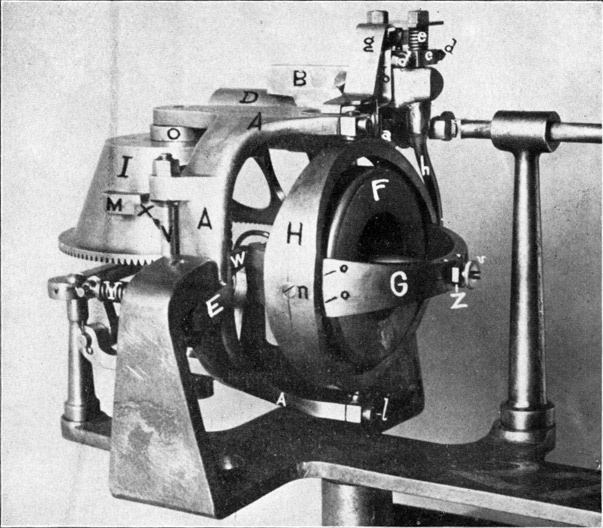
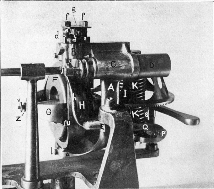
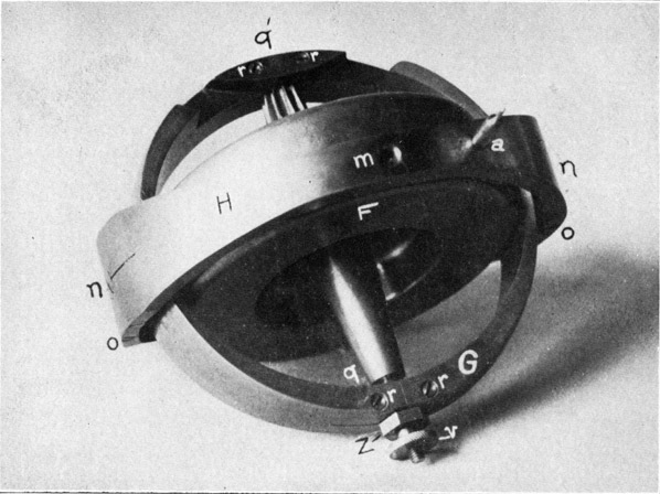
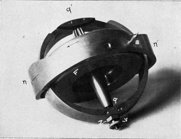
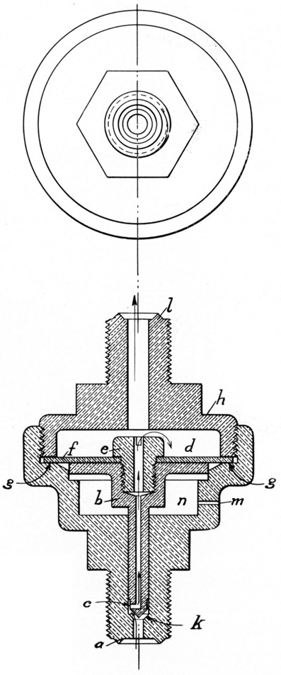
REDUCING-VALVE FOR OBRY GEAR.

Air enters at the nipple, a, on the end of the valve casing, passes into the axial channel of the valve, b, through the radial holes, c, and emerges into the pressure-chamber, d, through the axial hole in the screw, e.

The diaphragm, f, is of thin German silver, and is held on the seat, gg, by the cover, h, and to the valve by the screw, e.

The pressure in the chamber, d, causes the diaphragm, f, to yield, owing to its pliability, and as it buckles downward it forces the valve, b, downward until it is fully seated upon the valve-face, k. Supply air is thus cut off until the pressure in the chamber, d, is sufficiently reduced by the Obry steering engine through the nipple, l, when the valve again opens admitting air.

A hole at, m, permits the free escape of air that may leak by the valve into the chamber, n.

If necessary a paper washer may be laid on the seat, gg, tinder the diaphragm, f. Increasing the thickness of this washer makes the valve more difficult to seat, and hence gives greater average working pressure. The valves are adjusted in manufacture to work at 150 300 lbs.

plate24
 

PLATE XXV.
DETAILS OF OBRY GEAR.

A frame.
B valve-body.
C steering-engine
D air-cushion cylinder.
a control-pin.
b valve-arm.
c valve plug.
ee valve plug springs.
ff valve body-studs.
g valve guard.
h air-pipe to valve.
i piston-rod flange.
j steering-rod coupling.
a' valve.
b'b' radial channels in valve-plug leading to c'.
c' annular groove around valve.
d'd' longitudinal surface channels on valve.
e'f' annular grooves (top, middle, bottom) around valve-plug.
h'h' valve-plug ports.
i' channel from valve-plug to forward end of steering-engine.
k' channel from valve-plug to after end of steering-engine.
l'l' valve-plug ports.
m'm' radial exhaust-ports in valve.
n' axial exhaust-channel in valve.
o' supply air-channel in valve-body.
p' piston.
q' piston-rod.
y' steering-rod for vertical rudders.
b" clamp-screw for valve-arm.
plate25
 

PLATE XXVI.
DETAILS OF OBRY GEAR.

A frame.
C steering-engine.
D air-cushion cylinder.
E frame lugs.
S trigger for Obry gear.
A' stuffing-box in after bulkhead for vertical steering-rod.
B' vertical steering-rod extension.
C' rudder-connection.
D' spindle-yoke.
E'E' spindle rudders.
F'F' bearings for vertical rudder spindle.
h air-pipe to valve.
i piston-rod flange.
j steering-rod coupling.
r' lower arm of releasing-lever.
s' releasing-lever.
t' bell-crank.
u' link.
v' push rod.
w' upper arm of releasing-lever.
x' lower arm of adjustable-head.
y' steering-rod for vertical rudders.
z' guide for steering-rod coupling.
v" stuffing-box of push-rod.
plate26
 

PLATE XXVII.
DETAILS OF OBRY GEAR.

A adjusting-stand base.
B adjusting-stand pivot.
C adjusting aria.
D centering-pin socket.
E centering-pin socket.
F roller for adjusting-arm.
G stand for indicator-card.
H clamps for indicator-card.
I recording-pencil and holder.
J testing-tiller rod.
K testing-tiller bearings.
L frame lugs for mounting Obry gear.
M nipple for making air-pipe connection.
N releasing-lever.
O support.
plate27
 

Previous Part
More Plates
Whitehead Home Page
Whitehead Home Page


Copyright © 2013, Maritime Park Association.
All Rights Reserved.
Legal Notices and Privacy Policy
Version 3.00