Typewriter Maintenance, TM 37-305, 1944, presents the proper methods of adjustment and repair of the typewriters of WW II.
In this online version of the manual we have attempted to keep the flavor of the original layout while taking advantage of the Web's universal accessibility. Different browsers and fonts will cause the text to move, but the text will remain roughly where it is in the original manual. In addition to errors we have attempted to preserve from the original this text was captured by optical character recognition. This process creates errors that are compounded while encoding for the Web.
Thank you Robert Flory for the opportunity to scan this manual.
Note that the Index is in the back of the book on page 149.
Please report any typos, or particularly annoying layout issues with the Mail Feedback Form for correction.
United States Government Printing Office Washington: 1944
WAR DEPARTMENT,
WASHINGTON 25, D.C., 30 November 1944.
TM 37-305, Typewriter Maintenance, is published for the information and guidance of all concerned.
[A. G. 300.7 (8 Jan 1944).]
BY ORDER OF THE SECRETARY OF WAR:
G. C. MARSHALL, Chief of Staff.
OFFICIAL:
J. A. ULIO, Major General, The Adjutant General.
DISTRIBUTION:
Armies (10); Corps (10); SvC (10); Dept (10); PC & S (4) (Overseas) (1); QM Dep (15); QMSO, ASF Dep (15); ASF Dep (2); T of Opr (500).
For explanation of symbols see FM 21-6.
1
INTRODUCTION
1. General. Although a typewriter is a complicated piece of mechanical equipment, it can be said that rarely does the machine "wear out". Generally speaking these machines become so maladjusted that they cannot continue to produce satisfactory work until the adjustments are brought back to factory standards. A typewriter contains approximately 1800 to 2000 parts, which require approximately 20,000 different operations to manufacture. An operator typing at the rate of sixty words per minute actually motivates, with his or her fingers, 10,000 to 12,000 parts per minute, approximating 200 moving parts per second. If the typist maintains an even touch and perfect rhythm the typewriter responds perfectly. Uneven touch and erratic rhythm will cause a perfectly adjusted machine to skip, pile, crowd, or shadow. A flimsy or uneven desk will create a vibration that may result in any of these difficulties in a perfectly adjusted machine. An improperly installed ribbon or ribbon spool will create ribbon trouble and dim or unevenly typed impressions. Too often, because of some of these defects of operation, a mechanic will attempt adjustments resulting in maladjusting the machine.
2. Purpose. It is the purpose of this manual to present proper methods of adjustment and repair for the benefit of all personnel engaged in adjusting and repairing typewriters. Careful study of this publication will enable proper adjustments and repairs to be made with a minimum amount of time lost in such operations.
3. Method of presentation. Attempt has been made to consolidate into each section similar assemblies of all of the latest models of all makes of non-portable typewriters. As nearly as possible, the material is presented in order of adjustments to be made, so that adjustments, once made, will not be affected by subsequent adjustments to other assemblies. Sequence of Adjustments (see page 44) details the correct approach for adjusting each make of typewriter.
2
COVER PLATES
REMINGTON
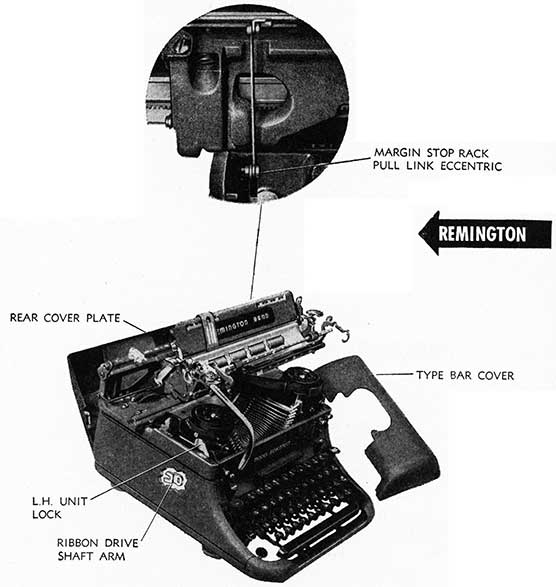
Cover Plates and Typewriter Unit of the Remington #17 may be removed in the following manner:
a. Top Typebar Cover may be removed, after moving carriage to the left to position Line Space Lever out of contact with Cover, by moving the Cover forward, lifting rear of cover upward to disengage from detents. Cover may be moved forward and off machine.
b. Rear Cover Plate may be removed by grasping top edge of rear (center) Plate at point just below Margin Bar and pulling outward. Hooks at bottom of Plate position on pins and plate may be disconnected by moving downward and out.
c. Typewriter Unit may be removed from Base Frame in the following manner:
(1) Remove Margin Stop Rack Pull Link Eccentric (inset).
(2) Remove Platen.
(3) Remove L.H. and R.H. Top Cover Aprons by removing binding screws.
(4) Depress Shift Lock.
(5) Determine that Ribbon Drive Shaft Arm (inset left side of machine frame) points down toward rear rubber foot of machine, see drawing.
(6) With right and left thumbs located on Unit Locks on either side of machine, pull forward while raising front end of unit keyboard upward so that the Ribbon Universal Bar will clear the Space Bar Line Lock Pawls (see Space Bar). Unit may be removed from frame.
(7) NOTE: Some machines require loosening of the Carriage Rail Assembly before the unit can be removed because of tight fit. For method of loosening Carriage Rail Assembly, see Main Carriage (page 8).
(8) As levers and parts of mechanism extend below the Unit, a small wooden jig may he constructed with a cleat at each end to hold unit while adjusting, which will permit operation of keylevers, etc.
d. Typewriter Unit may be replaced into Base Frame in the following manner:
(1) Depress Shift Lock.
(2) Position Ribbon Drive Shaft Arm as shown in drawing.
(3) Guide unit back into frame so that the Ribbon Driving Gear Stud seats itself properly in Fork of the Ribbon Drive Shaft Arm.
(4) With unit returning to Frame properly, press unit (top of keylever comb, right and left) towards rear and downward. If difficulty is experienced in returning unit to frame, check the Tabulator Bellcrank (See Tabulator). Check unit sides to determine that it is positioned properly in frame.
(5) With unit seated properly in frame, connect and readjust Margin Stop Rack Pull Link Eccentric. (See Margin Stops and Line Lock.)
(6) Replace Platen.
(7) Replace L. H. and R. H. Top Cover Aprons.
(8) Check position Space Bar Line Lock Pawls, which may be positioned between the wrong keylevers causing levers to bind.
(9) Check Typebars, Space Bar, Back Space, Line Lock, Shift Keys and Tabulator for proper operation without binding.
(10) Replace Rear Cover Plate.
(11) Replace Typebar Cover.
3
4
ROYAL
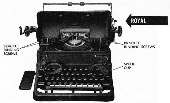
Typebar Cover and side plates of the Royal Typewriter may be removed in the following manner:
a. Typebar Cover. Remove Typebar Cover Bracket Binding Screws (2 on each bracket as indicated in drawing). Remove Ribbon Spool Cup Binding Screws (2 on each cup). Remove Ribbon Spool Cups. Typebar Cover may now be removed without affecting eccentric adjustments on Cover Bracket.
b. Top Cover Latches and Stops (to position cover properly in relation to ribbon spools) are located on front inside edge of the Typebar Cover. Stops may be formed to position Cover clear of the Ribbon Spools and Latches may be formed to hold cover locked down in position.
UNDERWOOD
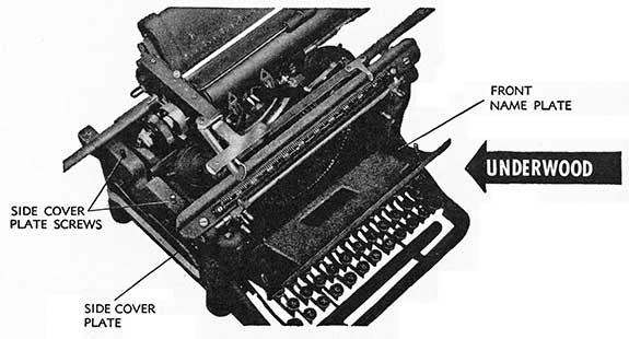
Cover Plates on the Underwood S model (with the exception of the Front Name Plate) are held in position with binding screws and may be removed without complication.
a. Front Name Plate may be removed by reaching hand inside front rail of main carriage, pressing Plate outward. Lower Lips (2) ride over the top of Keylever Comb. Name Plate may be lifted up and out.
b. Side Cover Plates are held in position with two screws, positioned as shown in drawing. Remove two screws and press out left hand cover plate. After removing two screws, it is necessary to remove Ribbon winding handle on R.H. side of machine, by holding Shaft tightly with wrench, screw may be backed out, and cover plate removed.
C. Rear Cover Plates may be removed by removing binding screws (one holding plate to frame, the other holding plate to Tabulator Housing).
5
6
WOODSTOCK
Rear Housing and Typebar Cover (Cowl) may be removed from the Woodstock in the following manner:
a. Rear Housing:
(1) Remove two Rear Cover Plate Binding Screws indicated in drawing.
(2) Check to determine if Manual Ribbon Reverse Rod Extensions are located on Reverse Rod. If so, remove them. Rear housing may be withdrawn (facing machine from the rear) exercising care to keep the sides parallel. Slight pressure with screwdriver applied between top plate and Rear Housing will assist in removal.
b. Type Bar Cover (Cowl) may be removed by depressing ears of Cover nearest platen as the Cover is withdrawn. Earlier models have Typebar Cover latches on either side, which may be released by pressing in as the cover slides off the top plate. In replacing Typebar Cover, rear edge of cover should be positioned on edges of Top Plate and the Plate moved slowly back, guided by the top plate. Caution: Do not force the cover onto the machine. It should move on freely, otherwise the ribbon mechanism may bind.
L. C. SMITH
Cover Plates may be removed from the L. C. Smith Typewriter in the following order:
a. Rear Top Cover Plate. Remove Rear Top Cover Binding Screws (one at either end in position indicated in drawing) which are made accessible by moving the carriage to the left and the right. Center carriage properly on base. Rear Top Cover Plate may be withdrawn from rear of machine.
b. Back Name Plate is held in position with two springs. It may be lifted up, springs disconnected and plate removed.
c. Right Hand Side Cover Plate. After removing Rear Top Cover Plate, remove Right Hand Rear Binding Screw, Right Hand Front Binding Screw and Right Hand Front Plate Binding Screws from positions indicated in drawing.
d. Left Hand Side Cover Plate may be removed in the same manner as Right Hand Side Cover Plate by removing Left Hand binding screws.
e. Front Name Plate. After loosening or removing Left Hand and Right Hand Side Cover Plates, the Front Name Plate may be lifted out of position.
f. Typebar Cover, which positions itself on Typebar Cover Brackets by two studs (one on either side) entering holes in brackets, may be removed (after Side Cover Plates are removed) by squeezing ends of Typebar Cover together (applying pressure to one side while holding the other) to disengage stud from Bracket. Typebar Cover Springs may be disconnected, freeing the cover. Care should be exercised in replacing these springs; if not positioned properly, they will bind the ribbon mechanism.
g. Paper Table Cover Plate. Remove two binding screws at either end. Remove Tabulator Universal Clear Lever Screw and Lever. Spring Cover Plate out over Tabulator Universal Clear Lever Shaft and remove from carriage.
7
8
MAIN CARRIAGE
REMINGTON
1. Proper fitting of the carriage is essential if alignment is to be controlled, and proper position of the carriage is necessary if Ring and Cylinder adjustments are to be properly made.
2. ADJUSTMENTS:
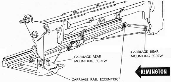
a. Carriage Rails. If the carriage is loose in its rails, proper fitting can be made by adjusting the Upper Carriage Rail. Adjustment should be made by loosening the four Upper Rear Carriage Rail Screws. The holes through which they fit into the rail, being oversized, permit adjustments to remove excess play. After adjustments, tighten the four Upper Rear Carriage Rail Screws and check the carriage to see that there is no bind or excess play in its entire end to end movement. Determine that the Carriage Trucks are in proper position by moving carriage to the left until it limits against its carriage end stop screw. Check both ends of carriage trucks to determine that trucks are inside the carriage rails. If not, with carriage moved to extreme left, loosen four Upper Rear Carriage Rail Screws and position carriage trucks just inside the left end of the carriage rail. Tighten Upper Rear Carriage Rail Screws. Determine that carriage rails are smooth and not pitted. If pitted they may be honed smooth with special rail file or stone.
Determine that Lower Carriage Rail cover is not bent, binding the carriage.
b. To Remove Carriage. Remove back panel. Disconnect drawband by loosening its anchor screw and attach draw-band to drawband anchor screw in machine frame. Back out Margin Stop Rack Pivot Screw, after loosening its lock nut, and remove Margin Stop Rack (do not disconnect Margin Stop Rack Pull Link Eccentric). As movement of the carriage forward or backward affects the Ring and Cylinder Adjustment, it is suggested that a mark be made on the typewriter frame at the bottom of the front carriage rail on each side, so that the carriage may be replaced with the least possible chance of affecting the Ring and Cylinder Adjustment.
Move carriage to the left and right, removing Left and Right Carriage Roll Rail Lower Eccentric Screw and Left and Right Carriage Roll Rail Lower Guide Screw. THE CARRIAGE MAY NOW BE LIFTED COMPLETE, AS A UNIT, FROM THE MACHINE. Determine if there are any shims located between the carriage and machine-if so, they should be replaced in the same position when carriage is returned to machine.
c. To Remove Carriage from Carriage Rails. Remove Tabulator Stop Set Arm Bracket by removing two screws as
shown in drawing. Remove two Carriage End Stop Screws as shown in drawing. The Carriage may now be moved out of the carriage rails to the right.
d. To Replace Carriage to Carriage Rails. With Carriage Trucks removed, slide carriage into carriage rails from the right. Replace two Carriage End Stop Screws in positions shown in drawing. Move Carriage to extreme left end with carriage limiting against its stop Screw. Insert Lower Front Rail Carriage Truck from left end of rail with left end roll of truck just inside left end of Lower Front Rail. Loosen three (3) Upper Carriage Truck Rack Screws. insert Upper Rear Carriage Truck from left end of Carriage Rail with left end roll of truck just inside left end of Upper Rear Rail. Check both ends (without moving carriage) to see that both trucks are within carriage ends. Then tighten three (3) Upper Carriage Truck Rack Screws. Replace Tabulator Stop Set Arm Bracket in position shown in drawing.
e. To Replace Carriage with Carriage Rails to Machine. On Elite-12 pitch machines, remove Escapement Unit first-see Paragraph 2b(4) Escapement Action. Return Carriage assembly to position with carriage rails fronting to mark previously made on typewriter frame at the bottom of the front carriage rail on either side. (If installing a new wide carriage assembly to frame it will be necessary to check and adjust Ring and Cylinder and Platen Parallel.) Replace Carriage Roll Rail Lower Guide Screws (one on each end of Carriage Frame) in position indicated in Drawing. Replace Carriage Roll Rail Lower Eccentrics (one on each end of carriage frame), positioned properly over screw hole in Carriage Frame and turn screw to hold in position. Test Ring and Cylinder Adjustment (see Ring and Cylinder), adjusting Carriage Roll Rail Lower Eccentrics until Ring and Cylinder are properly positioned. Both ends of the carriage Frame should be adjusted simultaneously to maintain parallel of the platen. When Ring and Cylinder adjustment has been made, tighten Carriage Roll Rail Lower Guide Screws. Replace Margin Stop Rack and properly position Stop Rack Pivot Screw so that Margin Stop Rack will be free on its pivots without end play. Tighten Stop Rack Pivot Screw Lock Nut.
Check position Lip "A" in its relation to Tabulator Stop (see keyset mechanism). Adjust stop set arm bracket to proper position, elongated slots are provided in Bracket for this purpose, then tighten Tabulator Stop Set Arm Bracket Screws.
TO REPLACE ESCAPEMENT UNIT IN ELITE-12 PITCH MACHINES-See ESCAPEMENT ACTION.
9
10
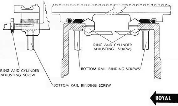
ROYAL.
1. Proper fitting of the carriage is essential if alignment is to be controlled. It is necessary that all loose play be reduced to an absolute minimum.
2. ADJUSTMENTS:
a. Carriage Rails and Fittings. Carriage clamps fitted to carriage rail casting adjust the carriage to the main carriage rail. Diagonal slots are provided in Carriage clamps for this purpose. It is essential that main carriage rail be true, otherwise binding will occur. All clamps must be adjusted to a snug fit, without binding.
Carriage Support Rail adjustment is provided by adjustment slots in Support Rail Bracket, adjustment being made with Support Rail Adjusting Screws on each end of rail. Tabular Rack roll must be free from bind in carriage support rail, and Rack roll binding screws must be tight. Carriage Support rail bracket binding screws must be tight.
b. Rail Balls and Pinions. Indicators are provided on Bottom rail for location of Bottom rail ball rollers and pinions. Unless positioned properly they may become disconnected from the rails. Rail Balls and Pinions should be set properly before Carriage clamps are adjusted; with carriage clamps loose, they may be positioned properly by using a thin screwdriver, to lift the carriage slightly to
permit their free movement. With carriage at extreme right, position of pinions is indicated on drawing of bottom rail.
c. Removal and Replacement. Facing machine from the rear, remove right hand Cover Plate Screws and Cover Plate. Replace drawband anchor screw in main frame. Disconnect drawband from carriage and attach to anchor screw.
Remove two carriage clamps shown in drawing. Loosen center carriage clamp. Move carriage to within one inch of right end (direction shown in drawing) tilting carriage back to disengage Tabular rack roll from support rail. Move carriage remaining distance to its right end (as shown in drawing) tilting carriage left end upward and slipping Back Space. Rack Lock Arm through opening between carriage end and rack bail. Carriage may now be lifted from machine.
To Replace. Position Bottom Rail balls and pinions properly in positions as shown in drawing; with carriage at extreme end of writing line, bottom rail pinion should be set three teeth inside end of rail. Replace carriage, feeding Back Space Rack Lock Arm through opening between carriage end and rack bail; then tilt carriage and move to left about 1 inch so that tabular rack roll returns to its position in carriage support rail (in this movement right bottom rail pinion and ball should move in with the carriage). Adjust clamps as outlined under Paragraph 2 a above. Replace drawband to carriage anchor screw. Replace right hand Cover Plate and Screws.
See instructions for removing Bottom Rail. (Motion and Shift Mechanism.)
WOODSTOCK
1. The position of rear carriage rail should not be disturbed. It is positioned accurately in its relation to abutment ring and its adjustments should be preserved.
2. ADJUSTMENTS:
a. The Front Carriage Rail should be adjusted to eliminate carriage play without binding the entire length of the carriage rails. In making front rail adjustment, front carriage rail screws should be loosened at both ends of rail. Adjustments should be made with Front Rail Adjusting Screws. There is one at each end of Front Rail just inside Rail Screw positions, between the rail and the top plate casting (front). At either end, and directly back of the segment, atop the front carriage rails, are located Front Rail Adjusting Screw Lock Screws. The rail adjusting screws are located in the center of the front rail V. In making adjustment, back out adjusting screw lock screws and using small screwdriver, make adjustment with the rail adjusting screws, being sure that, when completed, the rail adjusting screw is countersunk in the rail and does not protrude into the rail where it will damage the retainer rollers.
b. To Remove Carriage. Disconnect carriage drum strap from under right end of carriage attached to Drum Strap Screw. It can be held in position by fastening it to drum strap stud situated in top plate or by inserting piece of wire through eyelet and hooking .under edge of-top plate.
Remove bakelite carriage end plates, if machine is so equipped.
Remove Tabulator Bar by moving carriage to right end and remove right hand tabulator adjusting screw after backing out adjusting screw lock nut. Be careful not to lose washers on each end of tabulator bar' position them for return to proper pivot as they are of different thicknesses. Remove margin stop release lever by removing two release lever screws. Remove two front rail screws at either end of front rail. Place rubber band around top of
line finder and attach to key on keyboard. Holding front rail in place, tip machine on its back, then holding carriage and rail firmly on each end, slide backwards, up and toward you. (Be careful, do not catch front carriage scale underneath line finder screws.)
c. To Replace Carriage. Place machine on its back, pick up carriage, and center the roller retainer frame (to ascertain center position, look underneath carriage casting; there are two flat surfaces which will serve as a guide in centering the carriage retainer frame). Place front rail over roller retainer frame, taking care not to disturb position of retainer frame. Keeping ends of front rail even with ends of carriage casting, place the carriage over the rear rail, fitting the rollers properly in the rear rail V and the ends of the carriage even with the ends of the rear rail.
Bear down forward on carriage and front rail. The carriage unit and front rail will fall into their natural positions. Replace the front rail screws but do not tighten these screws. Carriage will run freely, but there may be lost motion which must be taken up by adjusting the front rail adjusting screws. When carriage rail is properly positioned, tighten the front rail screws. Fasten drum strap to stud under end of carriage. Replace margin stop release lever and the tabulator bar.
d. Roller Retainers. The roller retainers must be perfectly straight to prevent binding and the lips on the rear roller retainer must mesh smoothly in the slots of the front roller retainer. To place in position, hook the lips into slots taking care that they are bent over properly so that they will hold in position, but will not hind. Place rear roller in carriage groove and spring front roller retainer gently into position. Slide roller retainer from side to side, noticing whether arms clear bottom of carriage casting all the way, without binding in the rear anti-creep rack. Movement of roller retainers is governed by the anti-creep rack.
e. Anti-creep Racks. Place front rail in position and check the front anti-creep rack. If necessary to move the anti-creep rack in order to bring into proper alignment, loosen anti-creep rack screws. The racks must be so placed that the retainer pinion meshes smoothly, but firmly, in both racks along their entire length without binding and snugly enough to prevent their slipping out of place.
11
12
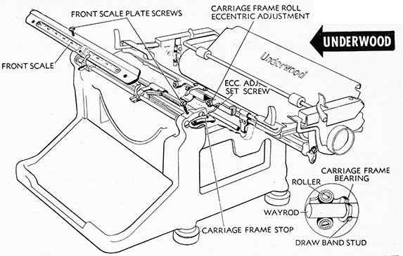
UNDERWOOD
1. The Underwood Typewriter carriage is fitted to a Way-rod with two Carriage Frame Bearings. (See inset in drawing.) Front Carriage Frame Rolls, positioned in the formed rails of the Front Scale Plate, perform the function of front rail rollers on other machines.
2. ADJUSTMENTS:
a. Wayrod and Carriage Frame Bearings. The carriage Frame Bearing must be fitted properly on the Wayrod with play reduced to a minimum of not more than .003". Adjustment is made by removing carriage from machine and forming by tapping the bearing sleeve at point of opening. Rollers must be free on their pivots. Carriage frame bearings must not bind the entire length of the wayrod. The Wayrod must be true throughout its entire length.
b. Carriage Frame Rolls (front). The left Carriage Frame Roll should set on the lower lip of the Front Scale Plate. This Roll provides the bearing for the front of carriage. The Right Carriage Frame Roll, which is eccentric, provides up-stop bearing and is adjustable to remove excess up and down play in front of carriage skeleton. Right Carriage Frame Roll should be adjusted to just clear the upper lip of Front Scale Plate. Adjustment is made with Carriage Frame Roll Eccentric after loosening Eccentric Adjusting Set Screw.
c. Carriage Frame Pointers must be aligned to Margin Stop Points and to front scale markings. Adjustment is made by loosening the Front Scale screws and Margin Stop Binding Screws and positioning Pointers properly.
d. Carriage Frame Stop should be adjusted, if necessary, by filing, to provide .001" clearance with Marginal Stop Release Lever when Margin Stop is in extreme Right Position contacting Margin Stop Release Lever.
e. To Remove Carriage. Remove Front Scale Plate screws as shown in drawing, being careful not to lose Carriage
Frame Stop. Slide Front Scale Plate out of engagement with carriage. Disconnect Carriage Draw Band from Carriage Draw Band Stud and position it on Draw Band Stud on Main Frame.
(1) Machines Equipped with Brake Band. Lifting front end of carriage up slightly, slide carriage to the LEFT. As the Right Brake Band Stud (right end of carriage) nears the Brake Band Guide on Tabulator Housing, tilt the left end of carriage downward so that Right Brake Band Stud will clear Brake Band Guide. Continue movement of Carriage to the Left to remove from Wayrod.
(2) Machines Not Equipped with Brake Band. Lift front end of carriage up slightly, slide carriage off, Wayrod to the RIGHT.
f. To Replace Carriage
(1) Machine Equipped with Brake Band. Place Right Hand Carriage Frame Bearing on Wayrod and move carriage to the right (lifting front end up slightly) until Right Brake Band Stud at right end of carriage nears the Brake Band Guide or Tabulator Housing. Tilt left end of carriage downward so that Right Brake Band Stud will clear Brake Band Guide. Continue movement of Carriage to Right feeding Left Hand Carriage Frame Bearing onto Wayrod. Continue movement to the right until Carriage centers properly on machine frame.
(2) Machines Not Equipped with Brake Band. Place Left Hand Carriage Frame Bearing on right end of Wayrod and move carriage to the left (lifting front end up slightly) until carriage is positioned properly on machine frame.
Replace Front Scale and Front Scale Plate Screws, positioning Carriage Frame Stop on Right hand (long) Front Scale Plate Screw.
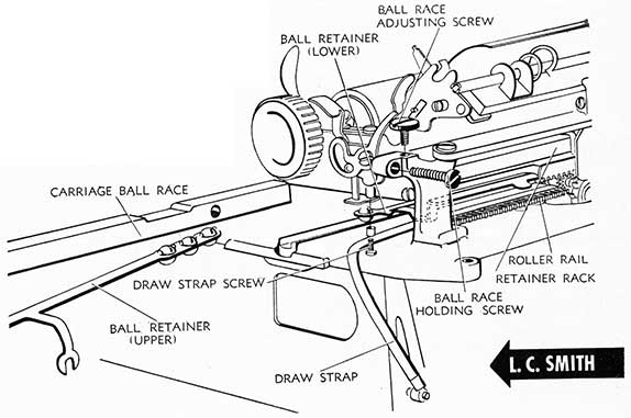
L. C. SMITH
1. Proper fitting of the carriage is essential if alignment is to be controlled. The L. C. Smith Carriage operates on Ball Bearings positioned in Ball Retainers, upper and lower. Ball Retainers are formed to lock bearings in position.
2. ADJUSTMENTS:
a. Carriage Rails. If the Carriage is loose in its rails, proper fitting may be made by adjusting Carriage Ball Race Adjusting Screws (see drawing) after loosening Ball Race Holding Screws. Lower Carriage Ball Race (rail) may be levelled by center adjusting screws (2) after loosening Lock Nuts, by entering screwdriver between keylevers 26 and 27 in the R. H. side and between keylevers 16 and 17 in the L. H. side. Carriage Rails must have a smooth, even surface. If rails are pitted, smooth flow of the Carriage will be affected. Rails may be re-surfaced with special formed file or stone to remove dents or pits.
b. To Remove Carriage. Disconnect Draw Strap by removing Draw Strap Screw and Washer, attaching Draw Strap to Frame Draw Strap Stud as located in drawing. Remove Ball Race Holding Screws (2). Remove Ball Race Adjusting Screws (one on each end of bracket-see Drawing). This is necessary only on the Super-Speed Models-not on
the Model #8. Remove Top Ball Race (rail) by sliding out. Remove Upper Ball Retainer. Remove Platen. Move left end of Carriage to the front of machine and move Carriage out of position to the left. Remove Ball Retainer Assembly.
c. To Replace Carriage. Place lower ball retainer in central position with wheel parallel to the starwheel shaft. Move carriage to rail position from the left, and center over lower ball retainer. Place top ball retainer centered over lower ball retainer in slotted arm of lower ball retainer.
Slide Top Race Rail over top Ball Retainer and into position. Insert right and left Ball Race Holding Screws, and tighten each side. Check Carriage to determine that it is free in its entire length. With margin stops at extreme right and left, move carriage to the right and to the left to determine whether ball retainers are centered properly. With Carriage to right and left, outside top Ball should position approximately 1/2" from the end of top race rail. If Ball Retainer is not centered properly, remove top anti-creep rack (viewing machine from rear) and position Ball Retainers properly to right and left; then replace Top anti-creep rack. Replace Ball Race Adjusting Screws, right and left, and adjust carriage in accordance with Par. 2a above.
13
14
SUB CARRIAGE
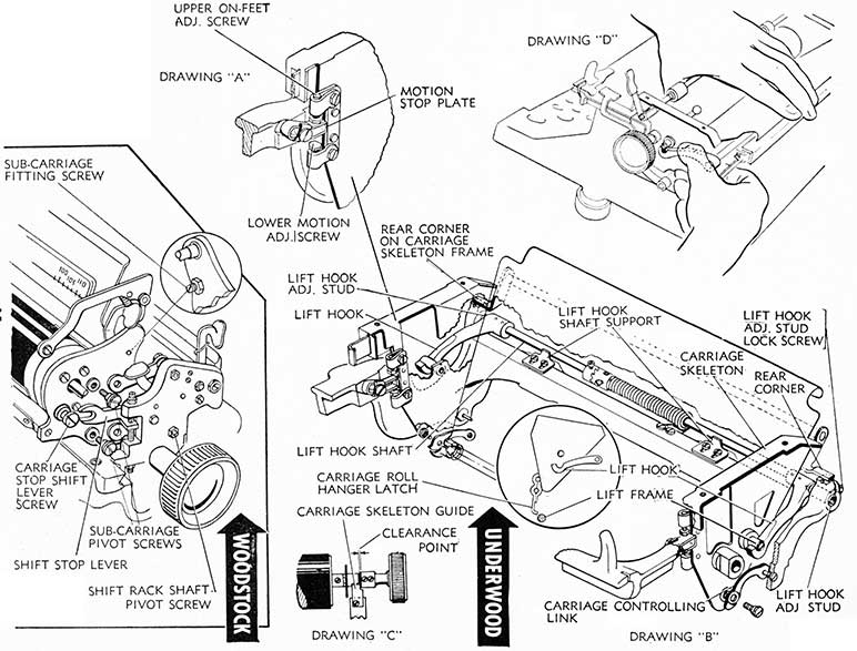
UNDERWOOD
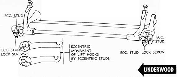
1. Proper fitting of the Underwood Sub-carriage is essential to securing good alignment and impression. The Sub-carriage pivots in the Carriage Skeleton on the left and right Lift Hooks. In normal non-shifting position, the Sub-carriage must seat uniformly on rear corners (right and left) of the Carriage Skeleton Frame, as shown in drawing. The Front corners of the Sub-carriage are positioned in and controlled by the Motion Stop Plates. In shifting, the Sub-carriage is raised by the action of the Lift Frame upon which the Carriage Roll rides. The Carriage Roll Hanger Latch (see inset) limits the upward movement of the Sub-carriage and keeps the Carriage roll positioned on the Lift Frame. The Carriage Controlling Links control the Sub-carriage in shifting and seating position.
2. ADJUSTMENTS:
a. Lift Hooks. The Lift Hooks must be parallel and Sub-carriage pivots must seat uniformly in the Lift Hooks, with a minimum of end shake. Adjustment is made by forming the Lift Hooks.
Lift Hook Shaft Supports must be parallel to Lift Hook Shaft with clearance not in excess of .002". Adjustment is made by loosening Lift Hook Shaft Support binding screws, positioning Lift Hook Shaft Supports, and tightening binding screws when adjustment is accomplished. Lift Hooks should be held down while making this adjustment. When adjustment is made, release Lift Hook Shaft Spring and see that hooks drop down freely and that shaft has a minimum of end shake. Restore tension to Shaft Spring after test or adjustment has been made.
Lift Hook Shaft must be adjusted to its highest position with a minimum of end shake. Adjustment is made with Lift Hook Adjusting Stud after loosening lock screws. As this adjustment also affects the Ring and Cylinder Adjustment Position, Ring and Cylinder should be checked for proper position.
Carriage Skeleton. The carriage skeleton (Drawing C) must be positioned to eliminate binding in both positions and to permit easy shifting. Adjust by moving Lift Hook Shaft to the left or right after loosening Lift Hook
Adjusting Stud Lock Screws and moving lift hook Adjusting Studs in or out. Tighten lock screws when adjustment has been made and check Shaft for freedom on pivots Also check Ring and Cylinder position.
The right hand Platen knob (Drawing C) must be adjusted to provide clearance point shown in drawing. Adjust by loosening R. H. Platen Knob set screws and moving knob. Test by turning knob completely around.
Lift Hook Spring should be adjusted to provide sufficient tension for light carriage shifting. Adjust by loosening spring clutch set screw and turning clutch. Tighten Set Screw when adjustment has been made.
b. Carriage Controlling Links. The Left Carriage Controlling Link is adjusted, by forming, to seat all four corners of the Carriage Skeleton on their resting places. The Right Carriage Controlling Link is adjusted, by forming, to remove rocking motion from Carriage Skeleton. The forming adjustment lengthens or shortens the Controlling Links. When Shift Key is depressed, carriage should move off all four corners simultaneously, and when released slowly, all corners should seat simultaneously.
c. To Remove Carriage Skeleton with carriage end cover plates removed, remove R. H. Carriage Controlling Link by backing out two screws (Drawing B). Remove L. H. Carriage Controlling Link by backing out one screw and disconnect Controlling Link from pivot pin.
Holding Lift Hook down with right thumb (See Drawing D), grasping hold of carriage skeleton in manner shown, lift skeleton up and towards the back of machine to disengage Carriage Roll Hanger Latch from Lift frame as shown in inset (Drawing B), and to disengage Motion Stop Screws from position on Motion Stop Plate. Then lift out.
d. To Replace Carriage Skeleton, determine that Lift Frame is held in down position. Holding Carriage Skeleton in manner shown in Drawing D, feed Skeleton Frame Bearings into Lift Hooks. Tilt carriage toward back of machine slightly to permit Carriage Roll Hanger Latch to engage Lift Frame properly, then seat down in proper position.
WOODSTOCK
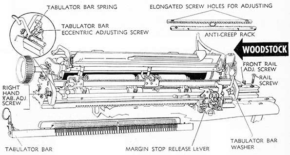
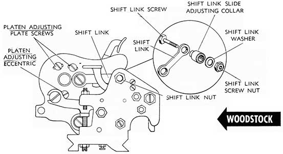
1. The Sub-carriage is fitted into main carriage frame and held in position by Sub-carriage Pivot Screws (two on each end of carriage). The upper pivot screw is fitted to sub-carriage frame through the Shift Link, which controls the Ring and Cylinder adjustment. The lower Pivot Screw is fitted to the sub-carriage frame through the Shift Rock Shaft Arms. The sub-carriage wheel, attached to sub-carriage frame and riding atop the shift rail, provides the upward movement of the sub-carriage in shifting. Proper adjustment of the sub-carriage fitting is necessary to insure good alignment and to assist in eliminating crowding.
2. ADJUSTMENTS:
a. Sub-carriage Adjusting Screws and lock nuts, located inside of sub-carriage frame ends, are adjusted to just touch the head of the Shift Link Screws to remove and shake in the sub-carriage, yet must not bind the sub-carriage when shifted. When adjustment has been made, tighten lock nut.
b. Shift Rock Shaft Pivot Screws (on each end of carriage) should be sufficiently tight to remove end play in the Shift Rock Shaft but must not bind the shaft. Adjust by loosening shift rock shaft pivot screw lock nut and turning screw clockwise to tighten; counter-clockwise to loosen. Test, by shifting, before tightening lock nuts.
c. Sub-carriage Pivot Screws (2 on each end of sub-carriage) and the Shift Stop Lever Screw on each end of sub-carriage should be checked for tightness. If necessary to tighten Shift Stop Lever Screw be sure to also tighten lock nuts.
d. To Remove Sub-carriage. Loosen R. H. Platen Knob set screws and remove R. H. Platen Knob. Loosen L. H. Platen Knob Set Screws; draw Platen Knob over to key into variable knob, then unwind (turn counter-clockwise) the L. H. Platen Knob until it is released from Platen Clutch Plate Wire. (See Platen.)
(Continued on page 20)
15
16
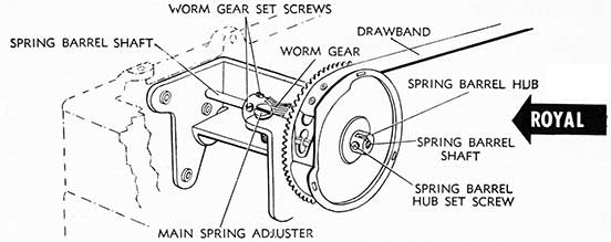
MAIN SPRING AND DRAWBAND
ROYAL
1. The carriage should be fitted properly to carriage rail and must operate freely before main spring tension adjustments are made. Drawband should be in good condition and properly secured to spring drum stud and to carriage drawband stud. Typewriter should be operated on a solid level table or desk, otherwise up-hill or down-hill travel will increase or decrease standard tension adjustment.
2. ADJUSTMENTS:
a. Main Spring Tension should be set at 1 1/4 to 1 1/2 pounds, or sufficient to move carriage to the extreme left.
(1) To Increase Tension turn Main Spring Adjuster (which is accessible through opening in Left Hand Rear cover plate by moving carriage to the right) counter-clockwise.
(2) To Decrease Tension turn Main Spring Adjuster clockwise.
b. Main Spring Drum:
(1) To Remove Drum, remove Typebars and Type Bar Links #1 and #2 (left side of segment) lettered Q and A to permit passage of Spring Barrel Shaft under bottom rail. Turn Main Spring Adjuster
counter-clockwise to release all tension, then turn it until Worm Gear Set Screws are visible. Loosen Worm Gear Set Screws sufficiently to allow Spring Barrel Shaft to be drawn through Worm Gear and Spring Barrel Hub. Drum may now be removed.
(2) To Replace Drum, reverse above procedure, being sure to properly assemble Worm Gear on Shaft before seating shaft in its position on Drum Bracket.
(3) To Remove Main Spring with Drum removed from machine, Drum Cover may be pried or loosened from Drum by tapping edge of cover with light hammer. Spring may be removed and disconnected from hub connection.
(4) To Replace Main Spring, place new spring with holding clamp in position over drum and force spring into drum as the holding clamp is released. Return cover to drum and tap into position.
c. Drawband should be checked to insure that there is no interference with ribbon worm shaft pinion which seats on drum gear. Drawband should not bulge at Drum connection end and should be formed flat at that end. Drawband must not be twisted between drum and carriage anchor screw.
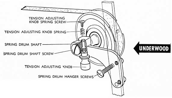
UNDERWOOD
1. Carriage should operate freely on Wayrod (which should be wiped clean with slightly oiled cloth) and be free in front rail before carriage tension is adjusted. Tension should be sufficient to move carriage to the extreme left end. Typewriter should be operated on a solid level table or desk, otherwise spring tension will be increased or decreased by tilt of table.
2. ADJUSTMENTS:
a. Main Spring Tension:
(1) To Increase Tension turn Tension Adjusting Knob clockwise.
(2) To Decrease Tension turn Tension Adjusting Knob counter-clockwise.
b. Main Spring Drum:
(1) To Remove Drum release all spring tension, by turning Tension Adjusting Knob counter-clockwise.
Disconnect Drawband from Drum connection. Remove two spring Drum Hanger Screws. Spring Drum assembly may now be removed from machine.
(2) To Replace Drum reverse above procedure.
(3) To Remove Spring from Drum turn Spring Drum Cover Plate counter-clockwise and remove. Main Spring may be disconnected from Drum Hub and removed. Care should be taken in removing or replacing Main Spring that the Spring is kept under control. New Springs are equipped with a holding clamp which may be removed as the Spring is entering the Spring Drum.
c. Drawband must be fitted smoothly to Spring Drum and properly connected to Carriage Drawband Anchor Stud. Drawband must not be twisted between the Drum and the Carriage Drawband Anchor Stud.
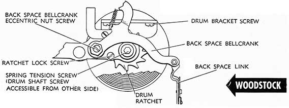
WOODSTOCK
1. The Mainspring drum must operate freely on its bearing and there must be no obstructions to the free movement of the drawband from the drum to the Drawband Stud on the right carriage end. Carriage should move freely in its rails without binding.
2. ADJUSTMENTS:
a. Main Spring Tension. There are three different methods of winding and releasing main spring tension on different Woodstock Typewriters. Main spring tension should be set at 1 1/2 to 1 3/4 pounds.
(1) To Increase and Decrease Tension: Woodstocks 220,000 to 583,000 are equipped with a ratchet pawl for the purpose of releasing tension by moving the ratchet pawl up and down, after backing out ratchet lock screw. Machines in this serial range are equipped with a thumb screw winding device for increasing tension.
Woodstocks 583,001 to 600,000 are equipped with a shaft screw but no ratchet pawl. To release tension, back out ratchet lock screw and brake the drum with fingers while it unwinds. To increase tension, hold drum with fingers while backing out Ratchet Lock Screw, then wind drum with fingers, resetting Ratchet Lock Screw between ratchet teeth when proper tension has been secured.
Woodstocks above 600,000 are equipped with a nut head on the shaft screw. With a socket wrench hold the shaft screw in position while unlocking Ratchet Lock Screw, then wind or unwind the main spring with the socket wrench, and reset Ratchet Lock Screw when proper tension has been secured.
(Continued on page 22)
17
18
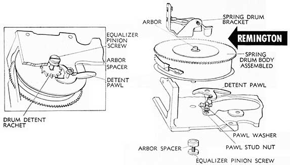
REMINGTON
1. Tension of the Main Spring should be sufficient to move the carriage to the extreme left. The carriage should be free in its rails before adjusting spring tension.
2. ADJUSTMENTS:
a. To Increase Main Spring Tension, turn Equalizer Pinion Screw. Detent Pawl will hold in each position, locking the Drum Detent.
To Decrease Main Spring Tension, work Detent Pawl up and down.
b. To Remove Drum Assembly. Release spring tension.
Disengage Drawband. Remove Spring Drum Bracket by removing two Spring Drum Bracket screws.
(1) To Remove Drum from Bracket, back out and remove Equalizer Pinion Screw.
(2) To Remove Spring from Drum, tap Geared Drum Cover to loosen, then remove. Remove Main Spring.
To Replace Spring in Drum, fasten outside end of new Main Spring on Main Spring Catch in Main Spring Drum. Position new Main Spring inside Drum, forcing Spring out of Clamp into the Drum. Replace Drum cover. Replace Drum Assembly.
L. C. SMITH
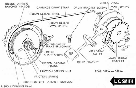
1. The heart of the operating mechanism of the L. C. Smith Typewriter is pivoted on or housed in the Main Spring Drum Bracket. This mechanism includes the Escapement Rocker, the Starwheel and Pinion, the Ribbon Driving Mechanism, the Back Spacer Mechanism and the Carriage Release Mechanism. Whenever the carriage moves, to the right or to the left, the operation is controlled by the mechanism of this bracket.
As in other typewriters, the Main Spring is encased in its own drum and the tension is controlled (increased or decreased) similarly. However, a special braking mechanism is provided in the L. C. Smith to brake the speed of the drum when Tabulating and this special braking mechanism also provides a slight braking power for the Ribbon Driving Ratchet to prevent a back lash in the ribbon.
On the Drum Shaft two ratchet wheels pivot free. Between these ratchets is a flat brake band. Tension between these Ratchet Wheels is provided by the Friction Spring which is compressed by the Friction Spring Nut and Lock Nut. The inner Ratchet Wheel (Ribbon Driving Ratchet) is engaged by the Ribbon Driving Pawl which pivots on the Spring Drum. As the Spring Drum turns, pulling the carriage to the left, the Ribbon Driving Pawl locks the Ribbon Driving Ratchet Wheel to the operation of the Drum, turning both Ratchet Wheels and the Ribbon Driving Pinion with it. The outer Ratchet Wheel (Ribbon Detent Ratchet) is engaged by the upper tooth of the Ribbon Detent Pawl, and, as will be noted in the drawing, both ratchet wheel teeth are set in the same direction and both pawls lock the movement of the Ratchets in the same direction. However, as the Ribbon Driving Pawl pivots on the Spring Drum its position is determined by movement of the drum, while the Ribbon Detent Ratchet Pawl. pivoting on the Tabulator Brake Bellcrank, remains in a stationary position and prevents the outer ratchet wheel from hacking up with the drum, while the brake tension also holds the inner. Ratchet Wheel stationary.
In Tabulating, the Tabulator Brake Bellcrank rear arm is moved downward and the lower tooth of the Ribbon De-tent Pawl moves in (upward) to lock the outer Detent Ratchet stationary. As the Ribbon Driving Pawl is engaged in the inner Ribbon Driving Ratchet forcing that ratchet to move with the drum in tabulating (carriage, is moving to the left) friction between these two ratchet wheels slows down the movement of the drum.
Tension of the Main Spring should be sufficient to move the carriage to the extreme right. The carriage should be tested for free movement in its rails without binding before adjusting Main Spring Tension.
2. ADJUSTMENTS:
a. To Increase Main Spring Tension loosen Ratchet Nut and turn Main Spring Ratchet to proper tension. Tighten Ratchet nut when adjustment has been made.
To Decrease Main Spring Tension loosen Ratchet Nut and using Adjusting Pallet, move in and out until desired tension is secured. Tighten Ratchet Nut when adjustment has been made.
b. To Remove Drum Assembly. The escapement mechanism, including the escapement rocker, back space mechanism and Main Spring assembly are assembled on the Main Spring Drum Bracket. Disconnect Back Space Link. (See Back Spacer.) Disconnect Pull Link from Pull Arm. (See Ribbon Cover.) Release Main Spring tension. (See Paragraph a above.) Disconnect Drawband from Main Spring Drum. Remove Escapement Connecting Screw on Universal Bar. (See Universal Bar.) Moving carriage to extreme right and left, loosen Spring Drum Bracket Top Plate Binding Screws, uniformly, alternating between them until Spring Drum Bracket is loose from top plate. Slide Bracket out between Tabulator Housing and side frame, to the right (viewing machine from the rear).
(1) To Remove Spring from Drum: Remove Drum Shaft Screw and Ribbon Detent Ratchet assembly. Remove Tabulator Brake Bellcrank, by loosening binding screw. Remove Main Spring Drum from Main Spring Shaft. Main Spring may now be removed.
(2) To Replace Spring in Drum: Fasten outside end of new Main Spring on Main Spring catch in Main Spring Drum, positioning new spring inside drum spring arms, slip spring out of clamp into the main spring drum. Place Main Spring Drum over Main Spring Shaft, snapping main spring down on shaft hub stud so that inside end of the spring will catch and position itself on huh stud. Replace Ribbon Detent Ratchet assembly. Replace Drum Shaft Screw. Replace Tabulator Brake Bellcrank by Replacing binding Screw, positioning properly.
c. To Replace Drum Assembly. Position Bracket under top plate, by moving through opening between Tabulator Housing and side frame. Reinsert Drum Bracket Top Plate Binding Screws in position as the Bracket is centered properly, replacing the screws and drawing the Bracket into locked position. by alternating from one binding screw to the other, until Bracket is properly locked' to top plate. Connect Escapement Connecting Screw on Universal Bar. Connect Pull Link to Pull Arm. (See Ribbon Cover.) Connect Back Space Link. (See Back Spacer.) Replace Drawband on Main Spring Drum. Wind up Main Spring tension with Main Spring Ratchet and when tensioned properly, tighten Ratchet nut.
19
20
MOTION AND SHIFT MECHANISM
REMINGTON
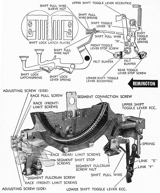
1. The shifting of the Remington #17 Segment is controlled, when the Shift Key is depressed, by the action of the Shift Pull Wire pulling the Shift Toggle Lever forward, in which action Link "E" moves the Segment downward to Shift position. The Shift Balance Spring provides tension to return Segment to normal position after shifting.
2. ADJUSTMENTS. Before attempting adjustments, determine that end shake in Segment has been reduced to an absolute minimum and that the Segment moves up and down freely in its race without binding. Adjustment may be made, after removing unit from frame, by disconnecting Segment Connection Screw and adjusting Segment Race fitting with Side Adjusting Screws (both sides) after loosening lock nuts. Check Shift Keys for bind. Segment should float almost to top of its race. Replace Segment Connection Screw. Segment should rest at top position, as governed by Segment Shift Stop Screws. Caution: Segment Shift Stop Screws are not adjusted to provide On-Feet or Motion. They are adjusted only to remove excess movement to Segment after On-Feet and Motion adjustments are completed with Shift Toggle Eccentrics.
a. On-Feet. The On-Feet Adjustment is made with the Upper Shift Toggle Lever Eccentrics in the following manner. (1) Back out both Segment Stop Screws, after loosening Lock Nuts. (2) Adjust Lower Shift Toggle Lever Eccentric, after loosening screw, positioning large side of Eccentric toward rear of machine as a temporary adjustment. (3) With Segment in Shift position, held down by the finger on Shift Kevlever, adjust Front Toggle Lever Stop Screw to bring Links "E" and "F" into a straight line. (4) Adjust Upper Shift Toggle Lever Eccentric, setting Capital Letters on their Feet. Release Shift Key and adjust Rear Toggle Lever Stop Screw to bring Rear Links into position to form a straight line.
b. Motion. With on-feet adjustment properly made, adjust Lower Shift Toggle Lever Eccentric to bring capitals and small letters into alignment. With Segment in normal non-shifting position, adjust Rear Segment Shift Stop Screw to remove up play in segment. Holding Segment in down position by depressing Shift Key, adjust Front Segment Shift Stop Screw to remove down play in segment. Test motion, and if off a trifle, back up on 'Rear Segment Shift Step Screw and raise Lower Shift Toggle Lever by adjustment of its Lower Shift Toggle Lever Eccentric. Readjust position of Rear Segment Shift Stop Screw.
c. Shift Keylevers should be adjusted so that top of Shift Key is approximately 1/16" above bottom row of keys. Adjustment may be made, after loosening Shift Pull Wire Nut, by turning Shift Pull Wire Sleeve Nut clockwise to raise the Shift Keys, counter-clockwise to lower them. Tighten Shift Pull Wire Nut when adjustment has been made.
After adjusting, check motion and on-feet and test segment for locking in non-shift position by pushing segment down with the hand. If not locking, check Shift Lock Lever extension, just below Shift Pull Wire Connection, to determine if it is limiting on Tabular Key Shaft, forming Shift Lock Lever extension, if necessary, to clear. Position of Shift Keys must be checked after forming to insure that they are positioned properly in relation to lower bank of keys, as outlined above.
d. Shift Lock Latch Plates must be adjusted to hold segment down securely and both Shift Lock Keys must lock with equal tension and with uniformity when both Shift Lock Keys are depressed simultaneously. Adjustment may be made, after loosening Shift Lock Latch Plate Binding Screws, and by positioning Shift Lock Latch plates properly, tightening binding screws when adjustment has been made. When adjustment is properly made, both Shift Lock Keys may be depressed and locked simultaneously; depression of a Shift Key should release the Shift Lock on that side a fraction prior to releasing the Shift Lock Key on the other side.
e. The Shift Toggle Lever Spring assists the Shift Balance Springs to return the Segment and Shifting Mechanism to proper position and also performs the function of holding the Shift Toggle Lever in inactive position, preventing rebound of the segment.
f. To Remove Segment (unit removed from Frame), remove type bars, after loosening Type Bar Fulcrum Wire retaining screw, by inserting follow-up wire in Segment Fulcrum Wire Slot. Typebars are formed for positions #1 to 42 inclusive and when removed should be laid out in order for convenience in replacing. Typebar links are special in size and shape and should be separated for replacement on typebars. Remove Segment Fulcrum Screws, after removing Segment Fulcrum Screw Nuts (lower drawing). Remove Segment Shift Bracket on which the Segment Connection Screw is fitted. Remove Segment Ball Stop. Segment may now be lifted up and out of frame.
To replace, reverse above procedure.
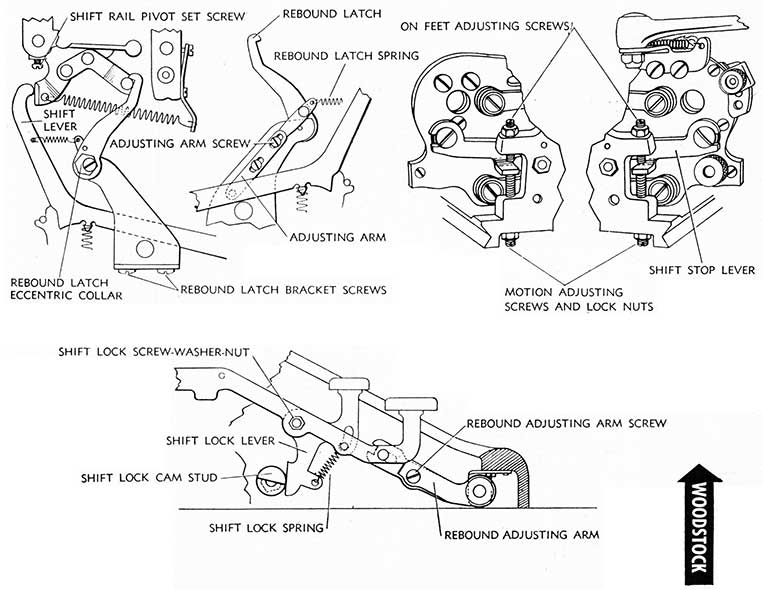
WOODSTOCK (Continued from page 14)
Remove the sub-carriage pivot screws (2 on each end of sub-carriage). Move carriage to left and disengage sub-carriage from Shift Stop Lever Arm, at the left. Move carriage to right and disengage sub-carriage from Right Shift Stop Lever Arm. Sub-carriage may now be lifted up and out of carriage.
e. To Replace Sub-carriage. See that Shift Rail is held down properly by Rebound Latch (See Paragraph f). Move carriage to right and setting sub-carriage in main carriage, place right carriage end pivot in right Shift Stop Lever Arm. Move carriage to left and place left carriage end pivot in left Shift Stop Lever Arm.
Replace sub-carriage pivot screws in their respective positions; by shifting sub-carriage, lower pivot screw will enter Shift Rock Shaft Arm. Replace Variable Spring (if previously removed) on Platen Clutch Plate Wire, turn clockwise until Platen Knob Shaft is tight against left sub-carriage end plate, then turn Platen Knob and Variable Knob counter-clockwise two complete revolutions; push platen knob to the right and tighten set screws. (See Platen.) Replace Right Hand Platen Knob and tighten set screws.
(Continued on page 24)
21
22
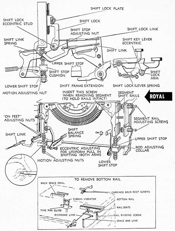
ROYAL
1. The Shift Mechanism of the Royal Typewriter involves the downward movement of the Segment (on Segment Shift Models) which is accomplished as the Shift Keylever is depressed by the forward movement of the Shift Link, pulling the Shift Arm down.
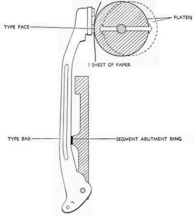
The face of the type is curved to fit the curvature of the cylinder and if On-Feet Adjustments are not made correctly, impressions will result which are light on the top or the bottom.
2. ADJUSTMENTS. Before attempting adjustments, determine that end shake in Segment has been reduced to an absolute minimum and that the Segment moves up and down freely in its rails without binding. Adjustment may be made with Segment Rail Adjusting Screws.
a. On-Feet adjustments are made with the Shift Stop Adjusting Nut (upper) positioning the Upper Shift Stop to control the downward movement of the Segment by contacting the shift stop cushion properly to maintain proper relationship between the curved type face and the platen. Adjustments must be made on both sides of the Segment with the Upper Adjusting Nuts, after loosening the top lock nuts. Adjustment must be uniform on both sides of the Segment and may be tested by inserting thin tissue strips between both Upper Shift Stops and Shift Top Cushions, setting the Shift Lock; determine by slippage if adjustments are uniform.
b. Motion. With the On-Feet Adjustment properly made, Motion Adjustment is made with the Motion Adjusting Nuts on either side of the Segment, after loosening Motion Adjusting Nut Lock nuts. After adjusting, test for uniformity on both sides of the Segment by inserting thin tissue strips between the Lower Shift Stops and Shift Stop Cushions and determining by slippage if adjustments are uniform. After adjusting check Segment Shift Lock.
c. Shift Mechanism:
(1) Segment Shift Lock must be adjusted so that the Segment will lock and release properly and all surplus play is eliminated. Adjustment may be made with Shift Lock Eccentric Stud after loosening lock screw.
(2) Shift Frame Extension should be adjusted by forming to permit of 1/16" further depression of the
Shift Keylever when the Upper Shift Stops have limited on the Shift Stop Cushions.
(3) Shift Lock Arm should be adjusted so that it will hold Segment in locked position but will release freely with slight pressure. Adjustment may be made with Shift Keylever Eccentric.
(4) Shift Lock Link should be adjusted so that Shift Lock will take firm hold on Shift Lock Plate. Adjustment may be made with Shift Lock Link Sleeve Nut.
(5) Shifting Arms should provide uniform pull in shifting. Adjustment may be made with Shifting Arm Eccentric (right side) as indicated in drawing.
(6) Shift Balance Spring should provide sufficient tension to return Segment to inactive position, after shifting, but should provide a light shifting touch. Shift Balance Spring Hook Arms on Shift Arms may be formed uniformly (both left and right) to increase or decrease tension.
d. To Remove Segment. Remove Carriage (see Main Carriage). Remove Keyset Stem (see Keyset Mechanism). Remove Segment Dust Plate Cover. Remove Line Finder Bracket by loosening two (2) Bracket Binding Screws available through holes in Segment. Insert Segment Rail Screws (shown in drawing) to hold rails intact. Remove Segment Rail Adjusting Screws (two on either side position indicated in drawing). Disconnect Top Shifting Arm Screws. Remove Motion Adjusting Nut and Lower Shift Stops. Remove Typebar Rest Arm connection to Segment (on both sides). Lift Segment and Typebar Assembly up and out.
e. To Replace Segment, reverse above procedure, adjusting Segment Rails, Pull Arm Eccentric and Motion and Line Finder Scale properly.
f. To Remove Bottom Carriage Rail. Remove Carriage (see Main Carriage). Disconnect Space Bar Link. Disconnect Bichrome Link. Remove Back Space Pawl. Remove Rail Binding Screws (2), one on either end of rail. Loosen Carriage Back Rest Screws. Bottom Rail and assembly (including Escapement Rocker) may now be removed from machine.
g. To Replace Bottom Rail, reverse above procedure, feeding Ribbon Vibrator into position on Type Bar Guide. Position Rail so that it seats properly on Rail Seats. Replace other mechanism previously disconnected.
WOODSTOCK (Continued from page 16
b. Main Spring Drum:
(1) To Remove Drum Bracket, release all spring tension by backing out Ratchet Lock Screw and unwinding drum by proper method outlined above. Unhook the drum strap from the drum. Disconnect the Back Space Link from the Back Space sub-lever by unlocking at point shown in drawing. Turn out the Back Space Bellcrank Screw, and remove the Back Space Bellcrank Eccentric Nut and the Back Space Belkrank. Tip the machine forward (viewing the machine from the rear) and remove the two drum bracket binding screws. The Bracket and drum may now be removed. The Drum may be removed, without removing the bracket, after releasing all spring tension and unhooking drawband by removing Drum Shaft Screw and spring tension screw. To replace Bracket and Drum, reverse above procedure.
(2) Main Spring: To Remove, with the Drum Bracket removed as outlined above, remove the drum shaft screw holding the drum to the bracket. Pull off the drum. Remove the drum disc by prying it forward and turning it clockwise. The spring may then be removed.
To Replace, place the new spring in the drum (with spring clamp holding spring securely), press the spring down into the drum as it is disengaged from the spring clamp. Turn the spring around to engage end of spring securely on the hub prong. Press the drum disc into position, at the same time turning it counterclockwise. Replace the drum on the bracket and replace the drum shaft screw, connecting the Back Space Bell-crank, Bellcrank Eccentric Nut and Screw and reconnect Back Space Link.
c. Drawband must be connected smoothly to main spring drum connection and must not be twisted between Spring Drum and Carriage Draw band stud.
23
24
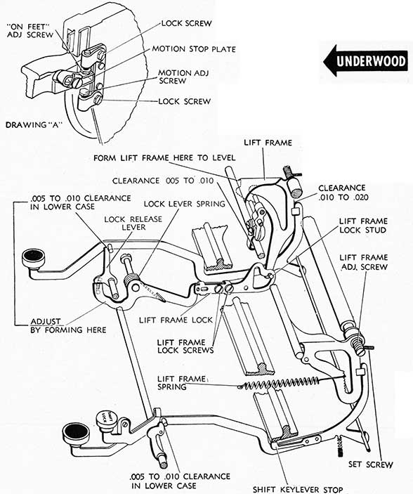
UNDERWOOD
1. The On-Feet Adjustment is the proper positioning of the platen in its relation to the curved face of the type. It is essential that the platen be of correct diameter and that its surface be smooth if best quality of impression is to be obtained. Platens ground down more than .010" from their original diameter will not provide a satisfactory type face fitting and should not be used.
The Motion Adjustment aligns.the capital and small letters to the same writing line.
The Shift Mechanism relates to the raising and lowering of the sub-carriage, locking the Shift Rail in either upper or lower positions as may be determined by position of the Shift Lock or Shift Keys. In accomplishing the Shift Lock and Release operation, depression of the Shift Lock Lever positions the Right Lock Release Lever over the keylever stud, and moves the Lift Frame in-the Lift Frame Lock Stud positioning itself in the front position of the Lift Frame Lock where pressure of the Lift Frame Lock retains it. When the Left Hand Shift Lever, which performs the function of the Shift Lock Release, is depressed, the Left Hand Shift Lever Stud contacts and moves forward (toward the front of machine) the Left Hand Lack Release Lever, which trips the Lift Frame Lock and moves the Lift Frame Lock Stud back to its non-shift position as shown in drawing, and releases the Right Hand Lock Release Lever from its position over the Right Hand Shift Lever Stud. It is essential that the sub-carriage (skeleton frame) be seated properly if these adjustments are to be maintained.
2. ADJUSTMENTS:
a. On-Feet. The Sub-carriage must first be paralleled and Ring and Cylinder Adjustment properly made. The sub-carriage must seat properly and uniformly on both rear corners (see Sub-carriage), and the Motion Stop Plates must clear the sub-carriage frame about 1/32", which adjustment is made by loosening Motion Stop Plate Binding Screw and positioning Stop Plate properly. The On-Feet Adjustment is made with the Upper On-Feed Adjusting Screws after loosening On-Feet Adjusting Screw Lock Screw. After making On-Feet Adjustment, check the sub-carriage to determine that it seats uniformly on both rear corners and on both Motion Stop Plates by using strips of tissue paper under rear corners and between On-Feet Adjusting Screws and Motion Stop Plate, determining by slippage if all seat properly.
b. Motion. Test motion with capital H and small h. If capital letters are lower than small letters, release Lower Motion Adjusting Screw Set Screws and turn Lower Motion Adjusting Screw counter-clockwise. If capital letters are higher than small letters, turn Lower Motion Adjusting Screw clockwise. By inserting a thin sheet of tissue between the Motion Stop Plate and Lower Motion Adjusting Screw on both sides of sub-carriage, and shifting carriage, determine by slippage that adjustments are uniform. Tighten Motion Adjusting Screw Set Screw when adjustment has been properly made.
c. Shift Mechanism:
(1) Shift Levers must work freely on their bearings and in the keylever comb, and there must be a clearance of .010" to .020" with Lift Frame, point indicated on drawing. Clearance with Lift Frame may be adjusted by forming Shift Keylever Stops at point of contact.
(2) Lift Frame must operate freely on its pivots with a minimum of end shape. Adjustment is made with Lift Frame Adjusting Screw after loosening lock screw.
Lift Frame Lock performs the function of locking the lift frame in both shift and non-shift positions. Pressure of Lift Frame Lock on Lift Frame Lock Stud must be sufficient to hold carriage in both positions. Pressure should be equalized with carriage in both positions. Lift Frame must be level in order to secure uniform pressure. Lift Frame may be formed at point indicated on drawing to level. Lift Frame Lock may be formed between Lock Stud positions by mauling.
Lift Frame Lock Spring tension may be adjusted by forming end of spring positioned on Lock Lever.
(3) Lock Release Levers (right and left) must clear Shift Keylever Studs (carriage in non-shift position) .005" to .010" as indicated in drawing. Adjustment is made by Forming Lift Frame Lock Lever at point indicated on drawing. Lock Release Lever (left) must clear Left Shift Keylever Stud (carriage in shift position) by .005" to .010". Adjustment is made by Forming Lock Release Lever.
(4) Carriage Roll Hanger Latch must clear Lift Frame Rod by .005" to .010" with carriage in non-shifting position, point indicated on drawing. Carriage Roll Hanger Latch may be formed to provide this clearance.
(Continued from page 20)
f. Rebound Latch. With the carriage in non-shift position, the Rebound Latch should be adjusted so that it rests lightly on carriage rebound lock plate latch stud. Adjustment is made by loosening Rebound Latch .Screw and turning the eccentric nut. The Rebound Latch (carriage lock) is released when shift keys are depressed:by the stud on the left hand shift lever. If sufficient up-or-down movement of rebound latch cannot lie secured with the eccentric adjustment, the Extension Adjustment, located on opposite
side of Rebound Latch Bracket, has .provision for bodily raising or lowering of the Rebound Latch.
g. Shift Rail. Check the Shift Rail for level. If not level, raise or lower Shift Rail by using Bender Tool on the rail or by prying under rail with a heavy screwdriver (be careful not to break the welding of shift rail arm). Shift Rail should fit snugly on its pivots without binding and should be centered on its pivots properly to prevent Ribbon guide from binding on Type guide. Pivot lock screws should be tight. (See Motion and Shift Mechanism.)
25
26
WOODSTOCK
1. The correct On-Feet adjustment determines both the correct position for subsequent adjustment of the motion as well as correct shifting position. The face of the type, being curved to fit the radius of curvature of the cylinder, necessitates that the On-Feet adjustment be correctly made. If the cylinder is either high or low in its relation to the curvature of the Type face, typed impressions will either be light on the top or light on the bottom, depending upon the cylinder position. A platen which has been ground down naturally loses some of its circumference dimension resulting in an improper fitting with the type face. For this reason a platen which has been ground down more than .010" from its original diameter will not provide a satisfactory type fitting and should not be used.
On-Feet, Motion and Shift Mechanism all relate to the raising and lowering of the sub-carriage in the Woodstock typewriter through the medium of the Shift Lever; the Shift Rail; the Rebound Latch, which locks the carriage in non-shift position to prevent vibration; and the Shift Stop Lever, which controls the upward throw and the writing line position, being limited by the Motion Adjusting Screws.
2. ADJUSTMENTS:
a. On-Feet. Type are put on their feet, in Upper Case (capital letters) by properly adjusting On-Feet Adjusting Screws, after first releasing lock nuts. Impression should be tested and adjustment of On-Feet Adjusting Screws continued until a sharp uniform impression is secured. The Platen must be paralleled before this adjustment is made. After making On-Feet Adjustment, hold adjustment screws with screwdriver while tightening lock nuts. Insert a thin sheet of tissue between stop of Shift Stop Lever at point of contact with On-Feet Adjusting Screw (on both ends of the carriage) and holding the shift key down, by friction pull on tissue sheets, determine that adjustments are uniform.
b. Motion. Test motion with capital H and small h. If capital letters are lower than small letters, release Motion Adjusting Screw Lock Nuts (on each end of carriage) and turn Motion Adjusting Screws clockwise. If capital letters are higher than small letters, after checking the sub-carriage to determine that there is no obstruction holding sub-carriage from its maximum travel upward, turn Motion Adjusting Screws counter-clockwise until positioned properly. By inserting a thin sheet of tissue between Shift Stop Lever and Motion Adjusting Screws at points of contact (both ends of carriage) determine by slippage that adjustments are uniform. Tighten lock nuts.
c. Shift Mechanism:
(1) The Shift Levers should be checked to determine that they are straight and not binding in the
comb, and that the end of the shift lever is so formed as not to strike the sides of the base frame posts which would cause the carriage to hang up after shifting.
(2) Shift Rail should be checked to determine that it is free on its pivots without excessive end shake. In centering shift rail, ribbon guide should be tested in red position, with shift lock set, to determine that shift rail is properly centered. If not, ribbon guide will bind, when keylever is depressed, and will not return to its normal position after impression has been made. Shift Rail Pivot Set Screw is accessible by setting Shift in locked position, turning machine up on its back and inserting long thin screwdriver between rear frame and sub-frame casting at either rear post position. Loosen Shift Rail Pivot Set Screw, force in (with screwdriver) the Shift Rail Pivot located in outside edge of Pivot Casting, tighten set screw and then check Shift Rail for binding and ribbon guide for centering properly on type guide.
(3) Shift Locks (on either side) are adjusted by turning the Shift Lock Cam Stud, after loosening Shift Lock Cam Stud Lock Nuts, toward the. front of the machine (clockwise on right hand, counter-clockwise on left hand side), so that the shift lock lever may be depressed deeper permitting more secure purchase. Both Cam Studs should be adjusted uniformly, so that you can depress both Shift Lock Levers- simultaneously and both will hold on the cam studs. If adjusted properly, Shift Keys depressed for releasing shift lock should require only minimum pressure to unlock shift, which pressure should be uniform on both shift keys. Adjustment is made on Rebound Adjusting Arm Screw after releasing lock nut. Shift must lock and release easily from both sides of the keyboard.
(4) Rebound Latch locks the sub-carriage in lower case (non-shift position) to prevent vibration of sub-carriage in typing. Rebound Latch should be adjusted so that it rests lightly on top of stud on Rebound Latch Plate attached to Shift Rail. Adjust by loosening Rebound Latch Eccentric Collar Screw and turning Rebound Latch Eccentric Collar until positioned properly. If this position cannot be attained with the Eccentric Collar (Rebound Latch not positioning high enough, or too high), Adjusting Arm, located behind Rebound Latch Bracket, may be adjusted by releasing adjusting arm screws and moving Adjusting Arm to raise Rebound Latch, or down to lower Rebound Latch. Tighten Adjusting Arm Set screws down after adjustment has been made. Readjust Rebound Latch Eccentric Collar, as may be necessary, after positioning Adjusting Arm.
27
28
L. C. SMITH
1. As the Shift Lever is depressed, the Shift Lever Connector moves the toggle arm and the rock shaft downward drawing with it the segment basket which performs the shifting operation. The segment moves in the segment ball race on ball bearings as indicated (right and left) in lower drawing. The Toggle Arm (on the right) controls the shift of the basket.
2. ADJUSTMENTS: Before attempting adjustments determine that the basket moves freely in the ball race with a minimum of end shake. Adjustment may be made with Ball Race Adjusting Screws and Nuts. Determine that end shake in Rock Shafts is reduced to an absolute minimum by adjusting pivot screws, after loosening pivot screw lock nuts.
a. On Feet. The Segment must first be adjusted to a snug fit in its ball races and all loose play in Rock Shafts must be removed, providing a smooth fit without binding. Adjustment may be made after loosening Ball Race Adjusting Screw lock nut by turning Ball Race Adjusting Screws to fit segment properly in its ball race. End shake in Rock Shafts may be removed after loosening Rock Shaft Lock Nuts, by turning Rock Shaft pivots, alternating from right screw to left screw in order that basket may be centered properly and there may be no bind in the Shift Rock Shafts. The On-Feet Adjustment on lA Models is made with the small letter (lower case) while the segment is in inactive position. Loosen Segment Stop Screw Lock Nut and back out On-Feet Adjusting Screw. Back out Segment Locating Plate Mounting Screw and position segment so that lower case letters will type a little heavy on the bottom, and light on the top. Now, turn On-Feet Adjusting Screw clockwise to make a uniform impression. Tighten Segment Stop Screw Lock Nut. (Late model #8 prior to 1A model reversed the position of the On-Feet Adjusting Screw and the Motion Adjusting Nut-the On-Feet adjustments being made with the top nuts instead of with the screw.)
b. Motion. With adjustment made as called for under paragraph a On-Feet and Segment in Shift Position-depressed (not locked), unlock Motion Adjusting Nuts and move the lower nut clockwise or counter-clockwise to bring the capital letters into alignment with lower case letters. Hold lower Motion Adjusting Nut while tightening top (locking) nut.
If adjustment has been made as directed above, there will be sufficient movement in segment for it to go down far enough to achieve proper motion. However, if the adjustment has not been made as indicated above (under Paragraph a-On-Feet) segment has previously been located too high and it will he necessary to retrace the steps or relocate Segment Locating Plate. If the latter is necessary, On-Feet Adjustment will have to be rechecked.
c. Shift Mechanism:
(1) If Segment has been located properly, as outlined above, Shift Balance Link will lock segment properly in inactive position.
(2) Shift Lock Latch. It is essential that the Shift Lock Lever be free when the Shift Key is held in depressed position. The Shift Lock Latch may be adjusted by loosening Shift Lock Latch Abutment Adjusting Screws and properly positioning Shift Lock Latch Abutment by raising or lowering the abutment until the Shift Lock Latch drops in under the abutment plate with slight pressure on Shift Lock Key. Tighten Shift Lock Latch Abutment Adjusting Screw.
(3) Shift Lever Adjusting Screws (both sides after unlocking lock nut) should be adjusted to provide about M6" drop on shift key before it picks up the basket mechanism.
(4) Lock Release Arm Assembly should be adjusted to provide approximately 1/16" clearance between right hand Shift Lever and the Right Lock Release Arm. If properly adjusted the Shift Lock Latch on the Left Shift Lock Lever will be positioned properly to release Shift Lock, when Shift Lever is depressed.
d. Keylever Assembly (viewing machine from beneath), if not positioned properly (moved to the rear too far or to the front too far) will affect the shifting mechanism. Three positioning plates attach Keylever assembly to main frame, and they are adjusted with sliding brackets when the Binding Screws are released.
Proper location of the keylever assembly should be tested before attempting any adjustments. The test may be made by shifting the basket with the Shift Lever. If the Type bar keylevers on either side or center of the keyboard bounce (move up or down) while shifting, it means that Sliding Keylever Bracket on the left side, the center, or the right side needs positioning, in whichever position the keylevers move. For example, if the keylevers on the right side bounce (move up or down) while shifting, the Sliding Bracket (underneath machine) on that side should be adjusted. This unbalanced condition will create a bind or provide a sluggish movement of the segment in shifting, and must be corrected before Shift mechanism is adjusted.
e. To Remove Typebar Basket. Remove On-Feet Adjusting Screw, after removing Segment Stop Screw Lock Nut and Motion Adjusting Nuts. Remove Rock Shaft Pivot Screw and nuts (center) at either side of Motion Adjusting Nuts. Remove Line Finder Frame Binding Screws located on top plate under the carriage which may be made accessible after removing platen by moving the carriage to the left or right-screws are accessible at end of Deflector Pan. Remove the Line Finder Frame. Disconnect Ribbon Carrier. Disconnect all type bar links from type bars (available at top of type bar nest). Back out Ball Race Adjusting Screw after loosening lock nuts (both sides). Type bar basket may now be removed. In replacing, reverse above procedure. It will be necessary to reset On-Feet and Motion, Ball Race, Rock Shaft Pivot and Line Finder Adjustments. (See paragraph 2.)
29
30
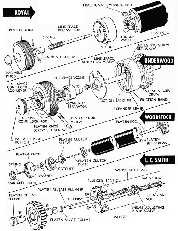
PLATEN
REMINGTON
1. The Remington #17 utilizes a platen with diameter of 1.594". It is essential that Variable Mechanism operate properly, without slippage, otherwise platen spacing will be affected.
2. ADJUSTMENTS:
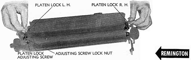
a. Platen should fit properly in carriage without excessive end play. Right Platen Knob is adjustable by threading onto Platen Shaft. It is held in position by Platen Locking Screw when adjustment has been made.
b. To Remove Platen, release Right and Left Platen Locks and lift platen assembly out of the carriage.
c. Platen Locks. The Tension of Platen Locks is determined by Platen Lock Adjusting Screws on either end of the carriage. Locks should be adjusted to hold the Platen shaft snug without binding. Tighten lock nut when adjustment has been made.
ROYAL
1. All model Royals utilize a platen measuring 1.486" in diameter. It is essential that the Fractional Cylinder End Springs (see VARIABLE) be of proper tension and cylinder end teeth are not worn; otherwise the Variable will not operate and creeping of the platen will result.
2. ADJUSTMENTS:
a. To Remove Platen, loosen left cylinder knob set screws. Loosen right platen set screw and remove Fractional Line Space Aligning Screw. Grasping the Right Hand Platen Knob and holding the plate, withdraw the Platen Shaft to the right. Platen may now be lifted out of machine.
b. To Replace Platen, place platen in carriage, fitting Fractional Cylinder end into ratchet. Feed Platen Shaft through right carriage and bearing and through platen. Replace Fractional Line Space Aligning Screw and aligning screw positioning holes in platen with Platen Knob Set Screws, tighten Platen Set Screw and Fractional Line Space Aligning Screw. Tighten Lift Cylinder Knob Set Screws.
UNDERWOOD
1. Underwood Typewriters #5 and #6 utilize a platen with diameter of 1.750". Platen should fit properly in carriage. If necessary, use a platen end reamer on wood core, after removing platen end, to secure proper fitting. Platen must be true and of proper size and condition.
2. ADJUSTMENTS:
a. The Right Hand Cylinder Knob should be fitted properly to right Carriage Skeleton Guide without binding in Shift position. Adjustment is made with Cylinder Shaft Knob Screws. After adjusting, turn knob and try shifting in each position.
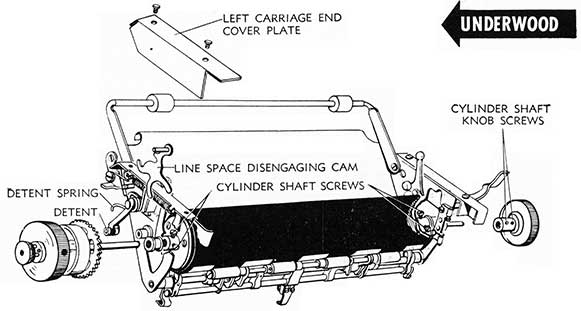
b. To Remove Platen:
(1) Remove Left Carriage End Cover Plate.
(2) Loosen Right Hand Cylinder Shaft Knob Screws (2) and remove Knob.
(3) Disconnect Detent Spring from position on Spring Post, permitting removal of Line Space Disengaging Cam.
(4) Loosen Cylinder Shaft Screws (2) on each end of cylinder.
(5) Holding platen with right hand, draw out cylinder shaft from the left.
(6) Platen may be removed from carriage.
c. To Replace Platen, reverse above procedure.
31
32
WOODSTOCK
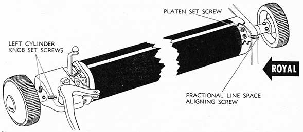
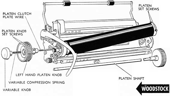
1. All Woodstock typewriters utilize a platen measuring 1.500" in diameter. Machines above 564,000 serial are equipped with a push-in friction variable which requires removal of Variable Knob and Left Hand Platen Knob before the Platen can be removed, as shown in drawing. Platen used on Woodstock machines above 564,000 serial has a metal platen end and platen set screws on right end of platen only.
Woodstocks below 564,000 serial utilize the etched Variable Knob for Variable line spacing and the platen may be removed without removal of the Left Hand Platen knob. To the left of the two Left Hand Platen Knob Set Screws, on the platen knob shaft, is the Platen Rod Screw. By backing out this screw and the two platen set screws on each end of the platen, the platen rod may be withdrawn from the right and the platen moved to the right and out. Care should be used in extracting the left end of platen from the clutch shaft lips to prevent breaking.
2. ADJUSTMENTS:
a. Platen Set Screws, on right hand end of late model machines, are pointed to fit embossed points drilled in Platen Shaft. It is essential that set screws be positioned in Shaft properly and heads are flush with metal end of platen.
b. To Remove Platen, loosen L.H. Platen Knob Set Screws. Move L.H. Platen Knob to the left to permit Variable Knob to Key into Platen Knob slot, then turn Platen Knob counter-clockwise (the Variable Knob will turn with it) until Variable Knob unwinds from Platen Clutch Plate Wire Thread. Variable Knob and Platen Knob may then be removed from clutch wire. Do not lose Compression Spring located in Platen Knob.
Loosen R.H. Platen Set Screws (2). As these screws are pointed, they should be backed out sufficiently to prevent scoring the Platen Rod.
Grasping the Right Hand Platen Knob and holding the platen, withdraw the Platen Shaft to the right. Platen may now be moved slightly to the right, up and out.
c. To Replace Platen, first inspect Line Space Lever mechanism to determine that it is in its proper place. Then place platen in sub-carriage with two platen set screws facing upward. Turn the platen slowly to align the three pins in the Clutch Sleeve with the three holes in Platen Core. Then push Platen to the left.
Insert Platen Rod through right sub-carriage end bearing and through cylinder, revolving it slowly as it nears the clutch end. Push it to the left until it finds its proper position in and through the clutch drum. Then turn the R.H. Platen Knob until knob set screws are in the same position as Platen Set Screws (facing upward) and Knob Shaft is up against sub-carriage end. Tighten Platen Set Screws.
Placing compression spring on Platen Clutch Plate Wire, turn R.H. Platen Knob until flat surfaces on left end of Platen Rod face upward. Fitting variable knob key into L.H. Platen Knob, replace on Platen Shaft and turn clockwise until platen knob, keyed to variable knob, is solidly against left end of sub-carriage frame. Back Platen Knob and Variable Knob out (counter-clockwise) two complete turns (3 if required)-push L.H. Platen Knob to right with Knob Set Screws in position over flat surface of Platen Rod. Position can be checked by reference to set screws on R.H. Platen Knob. Tighten set screws. Check Variable Knob for release and operation.
L. C. SMITH
1. The L. C. Smith Typewriter utilizes a platen with diameter of 1.750". Two types of Platen Latches are used, the one pictured in the drawing operating from the top of the carriage casting, and one operating from the outside front edge of the carriage casting on either end. It is essential that the platen be true in its entire length and provide a smooth surface for the benefit of clear type impressions.
2. ADJUSTMENTS:
a. Platen should fit properly in carriage without excessive end shake and without binding. Adjustment may be made by inserting or removing thin washers between the Platen Bushing and the Platen.
b. To Remove Platen, release Right and Left Platen Locks and lift Platen Assembly out of the carriage. In replacing Platen, check position of the Line Space Pawl, moving it up and out of the way before positioning Platen Shaft in its bearing in Carriage casting. Set locks properly.
33
34
VARIABLE
REMINGTON
1. The Variable should operate smoothly when the Variable Knob is depressed, to disengage the Ratchet. Release of the Variable Knob should result in instant return to ratchet operation.
2. ADJUSTMENTS:
a. Variable Knob must have end play when the left Platen Knob is tight, otherwise creeping of the platen under Line Space Lever operation may result. No end play in Variable Knob would indicate that the Clutch Dogs are not seating in Ratchet Slots, which would be caused by Clutch Dog Cams limiting on plunger, preventing action of the Clutch Dog Cams on the Clutch Dogs to seat them properly.
b. The Clutch Dog Cams should move freely and with good spring tension.
c. The Clutch Dogs should not stick in the slots of the Ratchet, and the Clutch Dog Springs should be in good condition and provide proper tension. If the Clutch Dogs are not positioning properly by the action of the Clutch Dog Cams, remove the left hand Platen Knob, Plunger, Platen Roll Bushing, Platen Roll Spring and Clutch Head (by removing three Clutch Head Binding Screws). Entering a flat pencil in position between Clutch Dogs to contact points of Clutch Dog Cams, push in to depress Spring Tension of the Clutch Dog Cams; slipping the Ratchet over pencil. position the Clutch Dogs properly in their relation to the Ratchet and to the flat surfaces of the Clutch Dog Cams. When seated properly, replace mechanism after removing pencil.
d. The Platen Roll Spring should be inspected for condition and tension.
e. The Ratchet should be positioned properly in its relation to the de-tent roll (see Line Space Lever).
35
36
ROYAL
1. Proper operation of the Royal Variable depends upon Fractional Cylinder End tension returning Cylinder End to locked position without binding and teeth being in good condition to permit proper mesh with Ratchet inside teeth. The Variable Knob is sweated to the Line Space Release Rod in manufacture and the spring is housed in the Platen Knob. If Line Space Release Rod is bent or deformed it will not operate properly.
2. ADJUSTMENTS:
a. Fractional Cylinder End Teeth if not in condition will not
seat properly in Ratchet and the Variable will not work. As replacing either the Cylinder End or the Spring is difficult, a new cylinder core is recommended.
b. Ratchet. If Variable teeth inside Ratchet are worn and will not seat Cylinder End teeth properly, the Ratchet should be replaced.
c. Tongue Washer must be in place in fractional cylinder end, otherwise Variable will not operate.
d. Variable Knob-Line Space Release Rod-Spring. Inasmuch as the Variable Knob is sweated onto the Line Space Release Rod in manufacture, it is difficult to remove and replace with assurance that the job will hold. It is therefore recommended that the complete assembly be replaced.
UNDERWOOD
1. Moving the Variable Push Button to the left releases all pressure of the Friction Bands on the Line Spacer Drum, and disengages the platen from ratchet control, which permits variable spacing. As the Push Button is pushed in (to the right), pressure of the Line Spacer Cone on the Friction Bands provides full pressure of the bands against the Line Spacer Drum, and locks the platen to the operation of the ratchet.
2. ADJUSTMENTS:
a. The Variable Friction Bands should apply sufficient pressure
against Line Spacer Drum to prevent slipping. Adjust this tension after loosening Adjusting Screw Set Screw. Turning Line Space Adjusting Screw clockwise increases tension; counter-clockwise decreases tension. Tighten Adjusting Screw Set Screw when adjustment has been made.
b. Line Space Cone Lock Rod Lever on Left Platen Knob should lock Line Spacer Cone securely when Variable Push Button is moved to the right. Adjust by loosening Platen Knob Screw Set Screw and Platen Knob Screw and moving Variable Push Button until Line Space Cone Lock Rod Lever locks over Line Space Cone Lock Rod properly. Tighten Platen Knob Screw and Platen Knob Screw Set Screw when adjustment has been made.
WOODSTOCK
1. Woodstock Typewriters, serials above 564,000, are equipped with friction type Variable pictured in drawing. Proper functioning of this variable depends upon proper assembly in carriage. (See instructions for Removal and Replacement of Platen.)
2. ADJUSTMENTS:
a. It is essential that proper spacing between Platen Knob and Variable Knob be maintained in order that the Variable may operate satisfactorily. Platen Knob set screws should be in place on flat surfaces of left end of platen shaft. If, as recommended under Paragraph 2c Platen, there is not sufficient clearance between Platen and Variable Knob after backing both out two complete turns and
pushing Platen Knob to right, disengaging the two, it may be necessary to back both out an additional complete turn in order to provide the necessary clearance between the two when the Platen Knob is moved to the sub-carriage end plate.
b. Ratchet Teeth inside the ratchet, if worn, will affect operation of the Variable by failing to permit the Platen Clutch Plate teeth to seat properly.
c. Platen Clutch Plate Teeth, if worn, will prevent proper seating.
d. Platen Clutch Plate Wire must be straight and centered properly to prevent binding in Platen Clutch Plate Sleeve and Platen Ratchet. If the Platen Clutch Plate Wire becomes unsoldered from its head, unless it can be soldered and centered properly, it should be replaced.
e. To Remove and Replace. See Platen for instructions.
L. C. SMITH
1. The pressure of the rollers against the ratchet drum, caused by the cam spring pressure against the Wedge, locks the platen to the operation of the Ratchet. When this pressure against the rollers is released, by turning the Platen Release Sleeve into the Platen Knob, the Platen Release Plunger is forced inward moves the Wedge Adjusting Plate inward and takes the Cam Spring pressure off the wedge, thereby releasing pressure on the rollers. When the Platen Release Sleeve is released (moved out of the platen knob) the Cam Spring returns pressure against the Wedge forcing the rollers out to apply pressure friction against the Drum and locking the platen to the action of the ratchet.
2. ADJUSTMENTS:
a. Rollers. As the pressure of the rollers against the drum controls the locking of the platen to the ratchet and as the Wedge is not adjustable, if the variable is creeping, one larger sized roller may be installed to take up the slack and increase the tension against the drum to correct the
creeping trouble. Rollers are available in the following sizes: .091", .094", .096", .099", .102". The standard roller is .091". In the absence of rollers, it is possible to form the point of Wedge down with three prongs to contact sloping edge of wedge plate to increase pressure on rollers somewhat.
b. Cam Spring must provide sufficient tension to maintain Wedge pressure on Rollers, when pressure of Platen Release Sleeve against Wedge Adjusting Plate (through the plunger) is released. Adjustment may be made by tightening (turning clockwise) Spring Adjusting Nut.
c. Platen Release Plunger must be positioned in Wedge Adjusting Plate so that when Platen Release Sleeve is turned into the Platen Knob the plunger will force Wedge Adjusting Plate and Cam Spring back to take pressure off the Wedge. Adjustment may be made by positioning Wedge Adjusting Plate after releasing Adjusting Plate Screw.
d. Plunger Spring must have sufficient tension to return Plunger to normal inactive position when released.
e. To Remove Variable remove three (3) Variable End Plate Screws (two of which are shown removed in drawing). The Variable mechanism may be removed from the platen.
37
38
TOOL SET
Tool No.
Description
44
Bender, arm, ribbon vibrator
2
Brush, dusting
15
Brush, type cleaning
120
Can, Oil, 1/2 oz. w/cap
69
File, rat tail, 6"
64
File, segment
71
File, warding, 4"
51
Gauge, soldering, Universal type
76
Hammer, Mechanic's
72
Handle, file, small
92
Hook, spring
137
Kit, tool, with tray, tool roll and glass containers
59
Paste, soldering, 2 oz. can
83
Pick, segment, Royal
NN56
Pliers, needle nose, approx. 7"
16
Pliers, parallel, side cutters, 6 1/2"
2
Pliers, three-prong, approx, 7"
9
Pliers, wire cutting, with mauling and type cutting jaws
The typebar in forward motion should contact simultaneously the Segment Abutment Ring and the Platen (with one sheet of paper inserted) regardless of carriage position. One of the following adjustments may be necessary to secure the desired contact:
RING AND CYLINDER ADJUSTMENT-Move entire platen in horizontal plane as indicated in drawing.
PARALLELING THE PLATEN-Move one end of platen in horizontal plane until typebar pressure on paper is constant across entire platen.
ON-FEET (see Motion and Shifting Mechanism) adjustment is the proper fitting of the type face to the curvature of the platen, by means of raising or lowering the platen, or, on Segment Shift machines, the segment.
Before making adjustments determine whether:
a. Platen is true by use of a straight edge.
b. Typebar is off the ring or off the cylinder by holding typebar against the platen or the Segment Abutment Ring. If off the ring, move platen back; if off the cylinder, move platen forward.
c. Platen is parallel to ring by moving carriage across rails while typebar is held to segment ring.
d. Platen is of correct diameter. If platen has been ground down more than .010" from its original diameter, type face, which is formed to fit the curved surface of the platen, will not strike squarely and equally on the platen, thus making a poor impression. In such instances the platen should be replaced.
40
REMINGTON
1. The forward or backward movement of the Platen on the Model 17 is controlled by movement of the Carriage Frame, which is held in position by Carriage Rear Mounting Screw (in adjustable slots) and controlled by Carriage Rail Eccentrics. The size of a Remington Model 17 platen is 1.594".
2. ADJUSTMENTS. (See Foreword on Ring and Cylinder.)
a. Paralleling Platen. Movement of one end of the platen in order to parallel the platen with a typebar held against the Segment Abutment Ring is accomplished by loosening Carriage Rear Mounting Screw on the side of carriage frame to be adjusted. Loosen Carriage Rail Eccentric Screw and adjust eccentric until platen is in proper position. Tighten Carriage Rail Eccentric Screw and Carriage Rear Mounting Screw.
b. Ring and Cylinder. Movement of the entire cylinder forward to meet a typebar held against the Segment Ring is accomplished by loosening the Carriage Rear Mounting Screws on either side of carriage frame; loosening the two Carriage Rail Eccentrics; and moving the carriage frame forward by alternate adjustments of the eccentrics until the typebar contacts the cylinder with one sheet of paper inserted. After adjustments have been made, tighten the Carriage Rear Mounting Screws (2) and the Carriage Rail Eccentrics (2). Test platen for results.
c. Note. Sometimes in installing a new carriage on a machine Ring and Cylinder, adjustment cannot be made with Carriage Rail Eccentric (they will not position in Top Plate holes). In such instances use large washer under Eccentric (removing eccentric from slot)-such screw operates only as a binding screw in this instance.
ROYAL
1. Setting of the Ring and Cylinder on the Royal Typewriter involves movement of the bottom rail and carriage assembly of the machine. Such movement automatically necessitates a recheck and readjustment of the Shift Stops, Segment Lock, Type Bar Trip, Escapement Back Limit Stop and the Universal Bar Ribbon Adjusting Screw. Size of a Royal Platen is 1.486" diameter.
2. ADJUSTMENTS. (See Foreword to Ring and Cylinder.)
a. Paralleling Platen. Movement of one end of the cylinder (including carriage and rail assembly) forward to Parallel platen with typebar contacting the Segment Abutment Ring may be accomplished after loosening Bottom Rail Binding Screw on side of machine involved. Turning Ring and Cylinder Adjusting Screw clockwise (to the right) moves the platen back. Turning Ring and Cylinder Adjusting Screw counterclockwise (to the left) moves platen to the front. Tighten Bottom Rail Binding Screw when adjustment has been made.
b. Ring and Cylinder. Movement of the cylinder (including carriage and rail assembly) forward to properly contact a typebar held in position on the Segment Ring is accomplished after loosening both Bottom Rail Binding Screws. Turning Ring and Cylinder Adjusting Screws equally counter-clockwise (to the left) moves platen forward (toward the front). Turning Ring and Cylinder Adjusting Screws equally clockwise (to the right) moves platen back (toward the rear). Check platen for parallel, both ends of carriage, before tightening Bottom Rail Binding Screws.
41
42
UNDERWOOD
1. Movement of the Platen, forward or backward, in order to set the typebars on the Segment Ring and on the Cylinder (Platen) is controlled by position of the Carriage Lift Hooks, which pivot on Eccentric Studs. These eccentric studs also provide adjustment for paralleling the Platen. Size of the Underwood #5 and #6 Platen is 1.750". The use of a platen ground down more than .010" is discouraged.
2. ADJUSTMENTS. (See Foreword on Ring and Cylinder)
a. Paralleling. Platen may be brought parallel to the ring by loosening Eccentric Stud Lock Screw on Lift Hook Shaft position involved and adjusting the Eccentric Stud, until the platen and typebar face meet squarely at all points. Tighten Eccentric Stud Lock Screw, when adjustment has been made.
b. Ring and Cylinder. Adjustment is made by loosening Eccentric Stud Lock Screws on either end of Lift Hook Shaft, and adjusting the Eccentric Studs by movement of one and then the other uniformly until the Cylinder (Platen) has been brought into its proper position in relation to the typebar held on the Segment Ring. Tighten Eccentric Stud Lock Screws.
WOODSTOCK
1. The necessity for Ring and Cylinder positioning is set forth in the foreword of this section. Before any Ring and Cylinder adjustments are attempted, the carriage should be properly adjusted to the carriage rails. Woodstock rear carriage rail position should not be altered-it is set properly in its relation to the ring. Size of the Woodstock Platen is 1.500".
2. ADJUSTMENTS. (See Foreword on Ring and Cylinder.)
a. Paralleling Platen. The left end of the platen is fixed in the sub-carriage frame. The right end of the platen can be moved by means of the Platen Adjusting Plate Screws and Platen Adjusting Eccentric provided in the right sub-carriage end plate. To adjust remove right end platen knob, loosen adjusting plate screws and turn platen adjusting eccentric until entire platen is parallel to the ring. Tighten lock nuts when adjustment has been made.
b. Ring and Cylinder. Movement of the entire platen is accomplished with the Shift Link Slide Adjusting Collars at each end of sub-carriage, the bottom edge of which is flat to permit sliding on carriage casting formed for the purpose. To adjust, loosen Shift Link Screw Nut on both ends of the carriage. Alternating, left and right, tap Shift Link Slide Adjusting Collar, until entire platen is in proper contact with the typebars when pressed against the ring. Tighten Shift Link Screw Nuts.
43
44
ADJUSTMENT SEQUENCE
REMINGTON
Carriage fitting and tension
Platen fitting
Variable
Line Space Lever
Paper Feed
Paper Bail
Margin Stops and Line Lock
Segment fitting and tension
Platen Parallel
Ring and cylinder
On-Feet
Motion
Shifting Mechanism
Escapement Rocker
Escapement Trip
Escapement Safety Zone
Universal Bar and Oscillator
Space Bar
Tabulator
Ribbon Feed
Ribbon Cover
Keylever Tension
Back Spacer
Aligning
ROYAL
Carriage fitting and tension
Platen fitting
Variable
Line Space Lever
Rack, Pinion and Starwheel
Paper Feed
Paper Bail (Clamp)
Segment fitting and tension
Platen Parallel
Ring and cylinder
On-Feet
Motion
Shifting Mechanism
Typebar action
Key action, touch control
Escapement Dogs, limits
Escapement Trip
Space Bar
Ribbon Cover
Margin Stops and Line Lock
Tabulator
Back Spacer
Ribbon Feed and Reverse
Aligning
UNDERWOOD
Carriage fitting and tension
Sub-carriage (skeleton) fitting
Platen fitting
Lift Frame and Shift mechanism
Variable
Rack, Pinion and Starwheel
On-Feet
Motion
Ring and cylinder
Line Space Lever
Paper Feed
Paper Bail
Margin Stops and Line Lock
Universal 'Bar
Escapement Rocker, dogs, etc.
Escapement Trip
Space Bar
Ribbon Feed and Reverse
Ribbon Cover
Tabulator
Back Spacer
Keylever Tension
Alignment
WOODSTOCK
Carriage fitting and tension
Sub-carriage fitting
Platen fitting
Variable
Sub-frame and keylever comb fitting
Platen Parallel
On-Feet
Motion
Ring and cylinder
Line Space Lever
Paper Feed
Paper Bail
Margin Stops and Line Lock
Shifting mechanism and shift rail
Rack, Pinion and Starwheel
Escapement Rocker, Dogs, etc.
Escapement Trip
Ribbon Feed and Reverse
Ribbon Cover
Tabulator
Back Spacer
Keylever Tension
Alignment
L. C. SMITH
Carriage fitting and tension
Tighten Drum Bracket Binding Screws
Margin Stops
On-Feet Adjustment
Motion Adjustment
Keylever Assembly, position
Shifting Mechanism
Universal Bar
Escapement Rocker, Dogs, etc.
Escapement Trip
Universal Bar Pick-up
Rocker Limit
Ribbon Cover
Space Bar
Line Lock and Release
Tabulator
Ribbon Feed
Typebar Action
Keylever Action and tension
Aligning
45
FOREWORD
Drawings of the paper feed mechanism of typewriters were made from positions necessary to properly locate adjusting mechanism. Instructions for each adjustment will indicate method to make these adjustment positions available to the mechanic.
Before attempting any paper feed adjustments, the paper feed mechanism should be checked after first cleansing platen and feed rolls with alcohol. The following causes for paper feed troubles should be explored and adjusted before making any mechanical adjustments on feed roll tension:
COMMON CAUSES FOR PAPER FEED TROUBLES
Causes
Corrections
Platen and feed rolls glossy
Should be cleansed with alcohol.
Paper feed rollers binding
Feed rollers should have a little end play and be absolutely free on their shafts.
Paper feed roller bearings dry
Bearings should be oiled sparingly.
Paper finger or Bail rollers binding.
Should be free on their shafts and applying equal tension to platen.
Platen binding or not fitted properly
See instructions under Platen.
Ratchet detent not contacting ratchet properly
Check ratchet and detent roller for position.
Worn ratchet or worn detent roller.
Check and replace, if necessary.
Insufficient ratchet detent tension.
Check and form or adjust spring to provide additional tension if necessary.
Improper sizes of Feed Rolls
Straight Edge assembly - all rolls must be of uniform size. Replace rolls if necessary.
Flat, cracked or inflated feed rolls
Replace feed rolls.
Paper Deflector (pan) improperly positioned
Adjust.
46
PAPER FEED
REMINGTON
1. Before attempting Paper Feed Adjustments, check common causes for Paper Feed troubles on Foreword Sheet of this section. If all causes are rejected, after testing, the trouble is then traced to the condition or tension of the rear and front feed rollers. The Paper Feed mechanism includes the Feed Rollers, the Platen, and the Paper Bail or Finger Rollers, all of which should be conditioned properly (all glaze removed by cleaning with alcohol saturated cloth) and all must be free on their bearings if the Paper Feed mechanism is to function properly. Feed roll assemblies should be straight-edged to insure that all rollers are of equal size. The Rear Feed Rollers (4) act as guiding rollers to guide the paper into the Front Feed Rollers which do the actual feeding.
2. ADJUSTMENTS:
a. The Rear Feed Rollers must have equal tension on both ends of the Shaft. Test for uniform tension by inserting
two strips of paper between platen and rear feed rolls only. By pulling these strips of paper, uniformity of tension can be determined by slippage. Adjustment is made with Rear Feed Roll Tension Adjusting Screws as indicated in drawing. These screws are accessible from rear of carriage by moving carriage to the right and left. Tension on Rear Feed Rollers should be less than on the Front Feed Rollers.
b. Front Feed Roller tension should be equalized across the three front rollers. Tension may be tested for uniformity as indicated above for Rear Feed Rollers. Adjustment may be made with Front Feed Roller Tension Adjusting Screws available from rear of carriage by moving carriage to right and left.
c. Paper Pan may be removed by lifting its studs from the paper trough support bracket with platen removed from carriage.
ROYAL
1. Before attempting adjustment for Paper Feed troubles, check common causes for Paper Feed troubles, foreword of this Section. If all causes are rejected, after testing, then the trouble may be traced to tension of front and rear feed rollers. The Paper Feed Mechanism includes the Feed Rollers, the Platen and the Paper Holder Rolls, all of which should be conditioned properly with all glaze removed by cleaning with alcohol saturated cloth, and free on their bearings if the Paper Feed Mechanism is to function properly.
2. ADJUSTMENTS:
a. Rear Feed Roll tension should be equalized on both ends of the feed roll shaft but should not be excessive. Test for uniform tension by inserting two strips of paper between the platen and the rear feed roll only. By pulling these strips of paper, uniformity of tension may be determined by slippage. Adjustment of Rear Feed Roll tension may be made with Large (rear) Feed Roll Adjusting Nuts located behind the platen, under the rack, on either end of the feed roll. Adjustment Nuts are available from the rear of carriage by moving carriage to right and left and tilting the machine up on its front frame cross member. Turning large feed roll adjusting nut clockwise will increase tension; turning Nut counter-clockwise will decrease tension.
b. Front Feed Roll tension should be equalized across the three front feed rollers and should be slightly less than tension on Rear Feed Roll. Tension may be tested for
uniformity by inserting three strips of paper between platen and the front feed rolls only. By pulling these strips of paper uniformity of tension may be determined by slippage. Adjustment may be made with Small Feed Roll Adjusting Screws after loosening Lock Nuts, which may be made available by removing Top Rail Cover, front lower edge of carriage. Turning Small Feed Roll Adjusting Screws clockwise will increase tension; turning counter-clockwise will decrease tension. Tighten lock nuts when adjustment has been made. The top Rail Cover is held in position with three screws, the outer screws being accessible by movement of the carriage to the right and left, while the center screw may be reached by raising the type bar cover, positioning the Segment in Shift Lock, and moving the carriage center slightly to the left of the type bar guide.
c. To Remove Feed Roll Assemblies, the rear feed roll and its rod may be lifted out of its bearing. The front feed roll rod nut may be backed out and the feed roll assembly removed.
d. Paper Pan should be adjusted to permit entry of at least 6 sheets of paper with accompanying carbons and there should be no friction when feed roll is released. If carbon copies fail to feed along with the original, the paper pan should be lowered. This adjustment may be made by forming the Pan at the back in line with bottom of rear feed roll to provide a uniform, gradual slope, rather than a sharp bend. The pan bend must be uniform.
47
048
UNDERWOOD
1. Before attempting Paper Feed Adjustment, check common causes for Paper Feed troubles on Foreword sheet of this section. If all causes listed are rejected, after testing, the trouble may then be traced to Feed Roll tension, Paper Rest clearance, or cylinder shield clearance.
2. ADJUSTMENTS:
a. The Rear Feed Rollers should have equalized tension across all four rollers. Test for uniform tension by inserting four strips of paper between platen and rear feed rolls only. By pulling these strips of paper uniformity of tension can be determined by slippage. Adjustment is made with the Rear Feed Roll Tension Adjusting Screws. As the Underwood carriage is easily removed, it is recommended that the carriage be removed from the machine to make and test these adjustments (see Main Carriage). Determine that Screw Locks on Feed Roll Tension Adjusting Screws lock the heads of screws properly.
b. Front Feed Rollers should have equalized tension across all four rollers. Test for uniform tension in same manner as specified for rear feed rollers. Adjustment may be made with Front Feed Roller Tension Adjusting Screws.
c. Feed Roller Tension Spring Retainers must be adjusted to Provide .003" clearance with Feed Roll Release Rod.
Adjustment is made after loosening Feed Roll Tension Spring Retainer Set Screw and moving Feed Roll Tension Spring Retainers to clearance position. Tighten Set Screw when adjustment has been made.
d. Feed Roll Release Rod must operate freely and must clear Feed Roll Release Rod Levers (point indicated on drawing) by .003" when in normal pressure applying position. With Feed Roll Release Lever engaged, feed rollers (front and back) must release simultaneously and should clear cylinder by .075". Adjustments are made by forming Feed Roll Hanger Release Lever Bracket up or down as may be necessary, but clearance of .003" with Release Levers must be maintained.
e. Paper Rest (Table) must be adjusted to clear Platen by .070". Adjustment may be made by forming Paper Rest Extensions.
f. Paper Deflector must be free, providing proper clearance with feed rollers, and adjusted with minimum of end play, which is adjusted by forming forked ends of the deflector. Deflector must clear platen in its entire length, adjustment being made by forming Bumper Ends to just contact the rear of Paper Rest. Front end of Deflector must clear the platen by .010" to .012" which may be adjusted by forming front edge of deflector.
WOODSTOCK
1. Before attempting Paper Feed adjustments, check common causes for Paper Feed troubles, Foreword of this section. If all causes are rejected, after testing, the trouble lies with condition or tension of front and rear feed rollers. The paper feed mechanism includes the Feed Rollers, the Platen and the Paper Bail or Finger Rollers, all of which should be conditioned properly (cleaned with alcohol saturated cloth) and all must be free on their bearings if the Paper Feed Mechanism is to function properly. Feed Roll Assemblies should be straight-edged to insure that all feed rollers are of uniform size and each roller is true in its entire length. Flat or cracked feed rollers should be replaced and the assembly checked for uniformity of size.
2. ADJUSTMENTS:
a. The Rear Feed Roller Tension should he adjusted so that the pressure of the rollers on the platen is sufficient to just carry the paper into the paper feed (front feed rollers). Tension must be uniform across the entire rear feed roll (or rollers) with slightly increased tension on the center adjustments. Test for uniform tension by inserting three strips of paper between the platen and rear feed rollers only. By pulling these strips of paper, uniformity of tension may be determined by slippage. Adjustment may be made with Rear Feed Roll Tension Adjusting Screws indicated in drawing. The End Adjusting Screws can be made accessible
by moving the carriage to the right and left end of the machine, while the center adjusting screws can be reached by facing the rear of machine (with rear cover plates removed), tipping the machine up on the front frame cross bar, and moving the carriage to the right until the sub-carriage wheel bracket is visible between the drum bracket and the carriage shift rock shaft. In this position, the adjusting screws for center tension can be seen, and by inserting a thin screwdriver between the third and fourth keylever from the right, directly behind the lower U-Bar and in front of the drum bracket, adjustment may be made. (It is not necessary to remove carriage.)
b. The Front Feed Roller Tension should be adjusted to about 2 3/4 lb. tension, or approximately three complete turns on the end adjusting screws and 3 1/2 complete turns on the center adjusting screw after the feed rollers have been brought up to the platen without any tension on them. Test by inserting strips of paper between the platen and each front feed roller as suggested in Paragraph 2a. above. Tension Adjusting Screws are accessible by following instructions outlined above.
c. Throat Opening (to accept more sheets of paper) is made with the Paper Feed Release Arm Bushing after loosening Paper Feed Release Arm Nut and Bushing Set Screw. Paper feed release arm ratchet teeth may be positioned on Arm Bushing to permit Release Lever to position as far back as possible, yet limiting clear of the Paper Table.
49
50
L. C. SMITH
1. Before attempting Paper Feed Adjustments, check common causes for paper feed trouble, Foreword of this section. If all the causes listed are checked and parts operate satisfactorily, the trouble may be traced to pressure (feed roll) tension or paper pan interference.
2. ADJUSTMENTS:
a. Feed Rollers. All Pressure (feed) Rollers must rest against the platen with equal tension, which must be sufficient to insure even feeding of the paper. Pressure (feed) Roll Arm Springs may be formed up to increase or down to decrease tension. Tension springs must be replaced in their slotted positions.
b. Roller Release Arms should be secured firmly to the Release Shaft and must be positioned to provide a little play between the Ribbon Release Arm and Pressure Roller Arm when platen is in position. Adjustment may be made with Roller Release Arm and Set Screw.
c. To Remove Pressure (Feed) Rollers, remove Platen. Remove Rear Pressure Roller Shaft Pivot Screw and remove Arm Pivot Clamp rear Screw, both ends of Roller Release Shaft. The entire Pressure Roller Assembly may be removed. Pressure Rollers may also be removed, by moving Platen. Remove Pressure Roller Release Locking Lever. Raise paper (Deflector) pan. Remove Pressure Roller Shaft Pivot Screws. Remove Pressure Roller Assembly.
To Replace. Replace rear Feed Roll Shaft Assembly and replace Rear Shaft Pivot Screw. Replace Front Feed Roll Assembly. Then tighten Arm Pivot Clamp Rear Screw. Clean Shaft with crocus cloth to polish for smooth surface and oil sparingly.
d. To Remove Deflector, remove front pressure roller pivot screws.