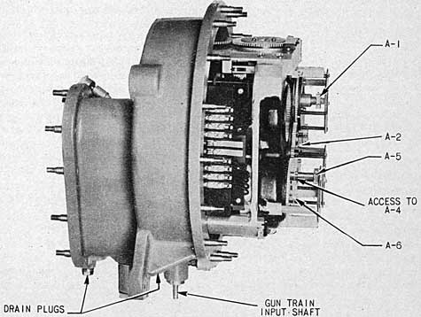
1. The mount stand designs are deck flange assemblies which include the mount training circle, pintle thrust bushing, supporting bearing, and holding-down bearing. These large circular assemblies are virtually alike in all details except the bearings and the lubricant retention facilities. A typical assembly is illustrated by figure 11.
2. Components.-Each stand assembly is composed of the following elements, with exceptions and differences as described in this chapter. Component arrangements are shown in figure 12.
Training indicator scale.
Pintle bushing.
Training stops.
Depression and training stop cam.
Baffle ring.
3. Stand design differences.-Stand designs differ as defined in the subparagraphs following.
(a) Stand Mark 10 Mod. 5.-This design is the typical assembly illustrated by figures 11 and 12 and described in the detail description of components.
(b) Stand Mark 10 Mod. 6.-Similar to Stand Mark 10 Mod. 5 except that the training circle is a steel casting instead of a carbon steel forging and the adjusting ring is steel instead of aluminum bronze.
(c) Stand Mark 10 Mod. 7.-Identical to Stand Mark 10 Mod. 6 except that the deck
FIGURE 11. - 3-inch Stand Mark 10 Mod. 5.
42
flange is thinner and requires a 1.25-inch thick circular liner when emplaced.
(d) Stand Mark 10 Mod. 8.-This design is the submarine deck emplacement assembly. It differs from the other designs principally in details of the bearings (rollers instead of balls), cadmium plating of all machined surfaces, and substitution of corrosion resistant materials for training circle and other parts. The adjusting ring is the same piece as for Stand Mark 10 Mod. 6 but is chromium plated.
Detail Description
4. Stand unit.-The main element of the assembly is a large circular steel casting or forging, 44.75 inches diameter. It provides deck flange by means of which the mount assembly is secured to the ship emplacement by sixteen 1.25-inch bolts. These are equally spaced on a 42.5-inch diameter circle. The unit includes an annular groove, 23.75 inches diameter, in which the lower race of the stand inner bearing assembles (see fig. 12 and par. 7). Machined surfaces of larger diameter provide seats concentric with this roller path race, for pintle bushing (carriage radial bearing), and bolting flange of the training circle (see fig. 12 and par. 5) .
5. Training circle.-The training circle is a large circular casting or forging secured to the unit described above by sixteen equally spaced 1.25-inch screw bolts, located on a 39.8-inch diameter circle. On its outer periphery is the training gear wormwheel, pitch diameter 37.50; a 14 1/2° involute type, 150 teeth incomplete circle. On its inner cylindrical surface a 29° screw thread, 35.3 inches diameter, provides seat for the adjusting ring of the holding-down bearing assembly (designated "outer bearing assembly," par. 8) . The training circle unit of Stand Mark 10 Mod. 8 is manganese bronze; other designs, steel.
6. Adjusting ring.-This ring mates with the unit above, as indicated and as shown in figure 12. It is an aluminum bronze casting in the Mark 10 Mod. 5 design and steel in the other designs, chromium plated for the wet mount assembly. An upper-interior flange bears directly on the upper race of the outer bearing assembly and thus functions to retain the carriage on the stand.
7. Inner bearing assembly.-The inner bearing assemblies are of two types: ball bearing in the Mark 10 Mod. 5 design, roller bearing in the Mark 10 Mod. 8 design.9 The former consists of an upper and lower race of special chrome-plated roller-path steel, 23.75-inch mean diameter, and 59 chrome-plated balls of 1.25-inch diameter. The lower race is pressed into an annular groove in the stand; the upper race is similarly seated in the carriage. The roller-bearing type consists of an upper and lower race of rolled-aluminum bronze, a roller separator of copper silicon alloy, and 41 pairs of 1.5-inch diameter aluminum-bronze rollers. Each pair of rollers is mounted on a pin which is seated in the separator. The rollers are of two lengths, a longer and shorter, staggered alternately in the separator.
8. Outer bearing assembly.-The outer bearing assembly for the Mark 10 Mod. 5 stand is like the inner-bearing assembly except that the ball-path diameter is 32.0 inches and carries 80 steel balls. The upper race is fitted into a pilot well in the adjusting ring; the lower race is fitted into a like well in the carriage. The bearing and the adjusting ring retain the carriage by preventing it from tilting during gunfire. The Mark 10 Mod. 8 stand is equipped with roller-type bearing similar to the roller bearing described in paragraph 7 except that it carries 56 pairs of rollers, all of equal length.
9. Training indicator scale.-The training indicator scale is a cast ring of phosphor bronze or steel plate which encircles the outer circumference of the stand and is secured to the stand by sixteen %-inch machine screws, equally spaced. The top surface of the ring, calibrated from zero to 360°, is graduated every degree and enumerated clockwise every 5°. This scale is read against the training-indicator pointer (see ch. IV) and is positioned at assembly so as to indicate zero or 180° train when the gun and mount are secured.
10. Pintle bearing.-A bronze bushing is fitted over the 27.50-inch diameter vertical-flange surface of the stand and is secured to it by four 3/8-inch brass screws. This thrust bushing is the pintle which centers the carriage
9 Roller bearing also used on some dry mounts.
43
FIGURE 12. - 3-inch Stand Mark 10 Mod. 5 Isometric Section View.
concentric with the mount-train axis and receives the horizontal component of the recoil brake.
11. Training stops.-The two training stops are of the positive lug type. They are fabricated from 1/2-inch sheet-steel plate and are secured to the stand base flange by two of the holding-down bolts. (See figure 12.) These stops are positioned at installation of the mount so that it will be impossible to train the line of fire into any of the ship's superstructure. They are contacted by a fixed training-stop bracket bolted on the front of the carriage and projecting down over the training-circle cover. On Stand Mark 10 Mod. 8 a depression and training stop cam arrangement, described below, is substituted for the positive-type lugs.
12. Depression and training stop cam.-The depression and training stop cam, used only on Stand Mark 10 Mod. 8, is a ring of cast copper-silicon alloy which is secured to the stand by six 3/4-inch bolts on a contact diameter of 20.80 inches. The contour of the cam is cut to suit the firing clearances for each installation.
13. Baffle ring.-The baffle ring is a bronze flanged ring which is mounted on the stand
within the inner-bearing assembly. It extends upward to nest with the 21.00-inch diameter well of the carriage. This acts as a grease retainer and shield for the inner-bearing assembly. The upper edge of this ring approaches to within a close clearance with the lower edge of the carriage cover-plate-retaining ring. Stand Mark 10 Mod. 8 does not include this part.
14. Deck flange liner.-The deck flange liner is a ring of 1.25-inch steel plate 44.75 inches in outside diameter which is employed to increase the thickness of the bolting flange of the stand. This liner is used with any stand having less than standard thickness.
Maintenance Instructions
15. General.-Maintenance of the two types of stand described in the preceding text comprises preservation of their respective parts and retention of the main-bearing clearances. Preservation has been anticipated, insofar as practical, through extensive use of noncorrosive alloys and chrome or cadmium plate of finished surfaces. Pitting and wear of plated surfaces can
44
and will occur if lubricating film is not maintained. (The primary function of lubrication in such assemblies is prevention of corrosion.) It is therefore imperative that the stands shall be frequently inspected as to adequacy . of lubrication.
16. Lubrication.-Lubricate the bearings according to the frequency and with the lubricants specified on the lubrication chart. For extreme cold weather lubrication of the roller path, radial and holding-down bearings, see instructions as to dilution and substitution of lubricants as prescribed in Ordnance Data 3000.
17. Preservation.-Inspect unplated surfaces for corrosion and adequacy of paint protection. Scale and clean down to bare metal any painted surfaces that are pitted and corroded. Do not repaint over oily, greasy, or damp surfaces. Scaled surfaces must be first-coated with red lead or zinc chromate primer.
18. Holding-down bolts.-Before and after firing inspect the holding-down bolts for corrosion, fracture and uniform tightness.
19. Drain holes.-Weep holes in Stand Mark 10 Mod. 8 must be kept clear, free from paint, grease, and dirt.
20. Trouble shooting.-Subsequent to mount installation, difficulty in training may develop. The maximum handwheel pull should not exceed 10 pounds at a 4.50-inch radius. In such event one of the following causes may be responsible, and the respective remedies are indicated:
(a) Rust may be present between foundation and stand. If so, disassemble stand and remove rust with emery cloth.
(b) Rust may be present on frictionless washers 8-Z-1117-2. If so, install new washers.
(c) Taper pins, 12-Z-49-63, securing bevel gears to shafts in the handwheel bracket may have dropped out. If so, replace taper pins.
(d) Dirt and chips may be present in hand-wheel brackets, training circle, or stand. If so, remove all dirt and grease from affected areas, clean surfaces thoroughly, reassemble, and lubricate.
(e) Plating of balls and races may have broken, peeled, or become pitted. If so, either deplate and replate balls and races or replace with new parts. When replacing balls or
rollers use a complete new set as all are furnished in sets graded as to size.
(f) Screws in stand bushing may have backed out because they were not staked and are binding on the carriage. If so, tighten screws and stake.
(g) Lubricant too thick due to cold weather. For cold weather precautions see chapter XI and appended lubrication charts.
21. Adjustments.-When the carriage is installed on the stand it is important that the adjusting ring be positioned and locked in place so that the holding-down bearing is correctly adjusted. The desired clearance, which should be checked periodically, is between 0.001 and 0.002 inch. This is best attained by turning the adjusting ring down tight and backing off until the vertical lift between the carriage and the stand is between 0.001 and 0.002 inch (backing off 2 inches, measured on periphery of ring, should approximate this clearance). Space gauge reading is to be taken at each 90° point on the ring circumference. If any readings exceed 0.005 inch the bearing assemblies should be checked for parallelism. The carriage may be jacked up with a pinch bar and the readings taken with a dial indicator clamped to the carriage. The carriage is successively rotated through 90° in order to obtain the quadrant-spaced readings. After the desired clearance is obtained, the hole for the lockscrew must be drilled, tapped, and counterbored, taking care that no chips fall back into the bearing. Install lockscrew as shown on the adjusting ring drawings and stake in place. Plug old lock-screw hole.
Disassembly and Assembly
22. Disassembly.-Before disassembly of stand, refer to figures 11 and 12; then proceed as follows:
(a) Remove the setscrew which locks the training circle and the adjusting ring together; using a large spanner wrench, turn the adjusting ring until the outer bearing is free.
(b) By the use of four jackscrews, release the inner bearing assembly and hoist the carriage pedestal out of the stand.
(c) Withdraw the four brass screws securing the thrust bushing to the stand and remove the bushing. Using the four jackscrews, unseat the inner-bearing assembly and remove.
ch2
RESTRICTED
NAVY DEPARTMENT, BUREAU OF ORDNANCE, WASHINGTON, D.C.
To all holders of Ordnance Pamphlet 811 (1st. Rev.)
Insert change; write on cover "Change 2 entered"
Approved by The Chief of The Bureau of Ordnance
OP 811 CHANGE 2
(1st. Rev.)
25 October 1944
1 Page Page 1
ORDNANCE PAMPHLET 811 (1st. Rev.)
is changed as follows:
3" GUN MOUNTS
MARK 20 MODIFICATIONS
MARK 21 AND MODIFICATIONS
MARK 22 AND MODIFICATIONS
Page 45, Paragraph 24(c): - Insert the following:
Relocation of the training indicator scales of the type with separate mounting lugs (Drawing No. 232842, pc. 1) can usually be accomplished without interference with the drain hole plugs in the base of the stand. A slight shift, however, of the alternate type of indicator scale with continuous mounting flange (Drawing No. 254069, pc. 1), recently adopted, will result in covering the drain holes in the stand.
When relocating a training indicator scale, first determine the position of the stand drain holes with respect to the relocated indicator scale bolting flange, and cut openings as necessary in this flange to provide access to the drain hole plugs.
DISTRIBUTION
Requests for additional copies of OP 811, First Revision, Change 2 should be submitted on NAVORD FORM 1, ORDNANCE PUBLICATIONS AND FORMS REQUISITION, to the nearest Ordnance Publications Distribution Center: Navy Yard, Wash, 25, D.C. Adak, Alaska; Mare Island, Calif.; Espiritu Santo, New Hebrides; Exeter, England; Pearl Harbor, T.H.; Manus Island, Admiralty Islands. Distribution Center mailing addresses should be obtained from List 10 nn of the Standard Navy Distribution List, or from the reverse side of NAVORD FORM 1.
Standard Navy Distribution List No. 28
2 copies unless otherwise noted.
(d) Withdraw the sixteen securing bolts and remove the training circle.
(e) withdraw the sixteen securing screws of the training-indicator scale and remove. Remove the two training stops. On Stand Mark 10 Mod. 8 remove the depression and training stop cam after withdrawing the six bolt fastenings.
23. Assembly.-Reassembly of the stand is performed in the reverse order of the routine above; observe the following instructions:
(a) When assembling the_ inner-roller bearing on the wet mount, take care that the rollers are mounted in the separator correctly, i. e., in alternating pairs of longer and shorter rollers. (See par. 7.)
(b) When assembling the depression and training stop cam on the wet mount, always point the inscribed arrow toward muzzle. Likewise, replace the training stops on other mounts with their proper holding-down bolts.
(c) Before assembling the training circle on the stand, clean the mating surface thoroughly and coat with O. S. 627-A, applied hot.
(d) When assembling the adjusting ring, coat the mating threads with antiseize, Ord. Std. No. 53;10 tighten into position with adjustment as described in paragraph 21.
(e) The diameter clearance between the stand bushing and the carriage-base well should not exceed 0.006 inch.
(f) When replacing the cover plate, bed in fresh paint and secure.
24. Installation.-Prior to installing the stand, the gun foundation on board ship must be prepared as follows:
(a) The stand is of a relatively light construction and must be provided with a very flat foundation to prevent straining or buckling. It has been found necessary to use a spotting plate on both wood and steel foundations and continue the bluing and spotting operation until approximately 75 percent bearing is obtained. The gun foundation should be flat within 0.005 inch in a distance of 45.0 inches if of wood, and 0.002 inch in a distance of 45.0 inches if of steel, and parallel to the normal waterline.
(b) Well dried white oak and Georgia pine have been found satisfactory for merchant ship
10"Lubriplate" is commercial equivalent.
installations. Teakwood is specified for all Navy emplacements.
(c) Use Bureau Ships drawing number 529641 or Ordnance Standard No. 8 for preparation of holding down bolts. Use working circle drawing for all mounts for location of the holding-down-bolt holes. Naval Gun Factory drill jig (shop assembly sketch 48060) may be used if available, for bolt-hole locations, thus insuring that there will be no interference with beams or girders. On some ships the mount may be shifted slightly to avoid such interference. If it is necessary to rotate the stand in relation to the centerline of the ship, then the training-indicator scale must be repositioned a like amount in order that the training-indicator pointer will be at zero when the gun bore - is parallel to the fore and aft centerline of the ship.
(d) Use No. 6 canvas impregnated with red lead between the foundation and the gun stand. If canvas is not available, a heavy coat of red lead between the stand and foundation will suffice.
(e) Lower the mount in position on the gun foundation and draw down on stand bolts uniformly. The mount should be tried in train continuously while the stand is being bolted. In event the training gear binds, the holding down bolts should be loosened and the mount trained completely around to determine whether the binding is due to malfunctioning of the assembly or distortion of the stand. If the fault is not in the training gear, the gun foundation surface should be rechecked for flatness. The holding down bolts should be flush with the locknut on the top side. If the bolt protrudes, the training bracket or training circle will strike the bolt and the mount will not train.
(f) Before the stand is finally secured, the training stops must be positioned so that it will be impossible to train the line of fire into any of the ship's structure. Where possible to obtain 360° train it may be desirable to provide depression rails of 2.50-inch outside-diameter pipe.
(g) Some wet mounts require training stops in addition to training and depression stop mechanism.
46
PLATE 11 - 3-INCH SIGHT, MARK 16 MOD 13 - GENERAL ARRANGEMENT
47
CHAPTER VI
3-INCH SIGHTS MARK 16 MODS. 5, 7, 8, 10, 12, 13, 15, 16, MARK 33 AND MARK 33 MOD. 1
General Description
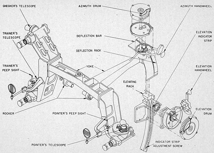
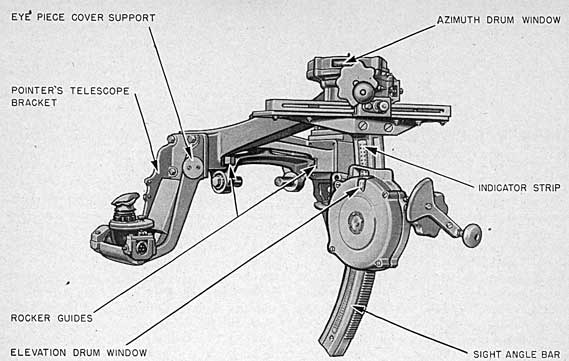
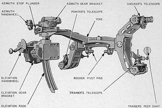
1. The sight designs listed in the title are slide-yoke-type assemblies of two differing arrangements. The Mark 16 designs are slide pivoted assemblies providing pointer, trainer and checker, open and optical lines-of-sight, arranged with deflection and sight angle mechanisms common to all lines-of-sight; Mark 33 designs have fixed mounting of the yoke on the slide, and provide open sights only, for pointer and trainer with separate sight angle off-set mechanisms for each line-of-sight, and do not include deflection off-setting arrangements. Plate 11 and figures 13, 14, and 15 illustrate typical features of all Mark 16 designs; figure 16 shows the assembly common to the Mark 33 design and its modification. The detail descriptions below separately describe the basic designs; the Mark 16 design is described in paragraphs 2 to 14 inclusive, the Mark 33 design in paragraphs 15 to 21 inclusive.
3-Inch Sight Mark 16 Modifications
2. Components.-The modifications of the Mark 16 sight listed in the title are composed of the following elements which are described below in the sequence listed.
3. Design differences.-Sights Mark 16 modifications indicated in the title differ as described in the subparagraphs following.
(a) Sight Mark 16 Mod. 5.-This assembly is the sight adapted for installation on Mounts
Mark 20 modifications. The azimuth movement (changed in latter designs) totals 400 mils.
(b) Sight Mark 16 Mod. 7.-This is a wet mount design which carries the submersion-type Telescope Mark 78, at the trainer's and pointer's stations. In all other respects it is similar to Sight Mark 16 Mod. 5 with the exception of the substitution of noncorrosive or plated metal throughout the assembly and the addition of bronze-channel liners in the rocker guides.
(c) Sight Mark 16 Mod. 8.-This assembly is identical to Sight Mark 16 Mod. 5 with the exception that the lines-of-sight of the pointer's telescope (Mark 74) and peep sight are 1.25 inches higher and the design is adapted for Mount Mark 22 and Mark 22 modifications.
(d) Sight Mark 16 Mod. 10.-Identical to Sight Mark 16 Mod. 5 except for increase of azimuth movement (600 mils total, 300 mils right and left).
(e) Sight Mark 16 Mod. 12.-A wet mount design identical to Sight Mark 16 Mod. 7 except that it includes increased azimuth movement as for Sight Mark 16 Mod. 10.
(f) Sight Mark 16 Mod. 13.-This assembly shown on plate 11, is Sight Mark 16 Mod. 8 with added azimuth movement as for Sight Mark 16 Mod. 10.
(g) Sight Mark 16 Mod. 15.-Same as Sight Mark 16 Mod. 13 except that sight-angle and sight-deflection receivers are mounted on the respective indicator-drum covers of the sight.
(h) Sight Mark 16 Mod. 16.-Identical to Sight Mark 16 Mod. 8 except that sight-angle and sight-deflection receivers are mounted on the respective indicator-drum covers of the sight.
48
FIGURE 13.-3-inch Sight Mark 16 Mod. 12, Left Rear View.
4. Sight elevating gear rocker.-The elevating gear rocker, a steel casting, transversely spans and is horizontally pivoted to the slide (see ch. III, par. 5). The rocker is also vertically pivoted and radially keyed to the yoke (see fig. 15). The two horizontal-pivot pins are threaded to the lower ends of the rocker; above them the two radial keys and the vertical center-pivot pin, each integral with the rocker, provide supporting bearings and guides for the yoke in azimuth motion. For the wet mount, Sights Mark 16 Mods. 7 and 12, the rockers are cast bronze and their azimuth-pivot bushings are flanged on their lower ends.
5. Yoke.-The yoke, an L-shaped steel casting, supports the sights and their operating gear. The yoke's transverse section or crossbar forms at each end a vertical bolting pad for a telescope holder. The crossbar also carries a pivot bushing and two radial keyways for the rocker.- From the crossbar's left half extends back a long tapered arm terminating in a cylindrical shell, open at the top, and in radial channel guides extending beneath the shell. The shell forms the housing for the azimuth drum; in the channel guides are inserted the deflection
bar and deflection rack. A setscrew through the rear guide projects into a groove in the deflection bar to limit sight deflection.
6. On Sights Mark 16 Mods. 7 and 12 the yoke is cast steel, cadmium plated, and carries bronze-channel liners in the rocker guides. Six bronze telescope-cover plugs with peripheral threads are secured to each yoke at convenient locations. The covers are removed from the telescopes and threaded to these plugs prior to using the telescopes.
7. Telescope holders.-The telescope holders, cutout-channel steel castings, project outboard from the yoke. The pointer's and trainer's telescope holders are keyed and bolted to the yoke; the sight checker's telescope holder is keyed and bolted to the trainer's holder. Secured to the sight-checker's holder is a leather-covered sheet steel guard which projects out under the telescope's color-filter housing and functions as a head guard for the trainer. The outer end of each holder supports a telescope in two bearings: a forward swivel bearing and a rear adjustable bearing. By turning the rear bearing's four adjusting screws, the telescope's line of sight can be elevated and deflected into
49
alignment. On Sights Mark 16 Mods. 7 and 12 the holders are made of copper alloy.
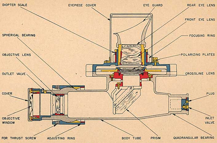
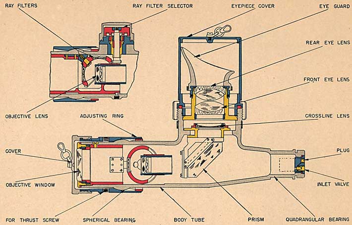
8. Telescopes.-Sights Mark 16 Mods. 7 and 12 are equipped with Telescope Mark 78 at pointer's, checker's, and trainer's stations. All other sight designs are equipped with Telescope Mark 74 at all stations. These instruments are fixed-power, prismatic, antiaircraft gunsight designs with assembled arrangements as illustrated by plate 12 (Mark 74) and plate 13 (Mark 78). Both instruments are described and illustrated in Ordnance Pamphlet No. 582, first revision. They are similar designs differing as to watertightness, color filter selections,11 and optical characteristics indicated in the tabulation below.
Mark 74
Mark 78
Magnification
6.11 X
4.0 X.
True field
10°
15°.
Exit pupil
5.5 mm
5 mm.
Eye distance
26 mm
27 mm.
Eyepiece-adjustment limits, diopters.
+2 to -4
Fixed (-3/4)
9. Open sights-The peep sights are mounted slightly above the pointer's and trainer's telescopes on short brackets fastened to the telescope holders. Each sight is composed of a bar, a front ring sight, a rear sight, and (on some mounts) a guard. The bar is held rigidly in its bracket and parallel to the telescope's line of sight. The front sight ring encloses five parallel, equispaced wires. These wires are mounted horizontally in the pointer's sight, and each wire indicates a sight-angle difference of two degrees. The wires, are mounted vertically in the trainer's sight and each wire indicates a deflection difference of 20 mils. Each ring is held at right angles to the bar and is adjustable vertically. The rear sight, supported with its base held at right angles to the bar, is adjustable laterally. These adjustments are used in aligning the peep sight. The guard, secured to the sight bracket if installed, protects the sight from above.
11 Color filters for Telescope Mark 74 are yellow, red, clear, and variable density; those for Telescope Mark 78 are yellow, dark neutral, clear and light neutral.
10. Azimuth gear.-The azimuth gear assembly comprises a deflection bar and rack, azimuth gearing and drum, and an operating hand-wheel. The deflection bar, a cast-steel arc, is secured to a bolting pad on the upper end of the sight-angle bar, and is bolted to the deflection rack. This rack is of cast steel and carries vertical teeth on a pitch radius of 32.25 inches from the sight azimuth-pivot pin. The rack meshes with a pinion gear which is on the lower end of the azimuth wormwheel shaft. Midway up this shaft the wormwheel is keyed on. This wormwheel meshes with a worm which is carried on the azimuth handwheel shaft. The upper portion of the wormwheel shaft carries a flanged collar which is pinned to the shaft. Secured to this flange by screw bolts is the azimuth drum, which carries duplicate graduations on the top surface and on the outer surface of the rim. These inscriptions are in mils and are graduated every two mils and enumerated every 10 mils from 300 mils to 700 mils. These graduations and enumerations are internally illuminated and are cut clear through the drum; they are filled with white lacquer after the face of the drum has been coated with black enamel. The operating handwheel shaft and worm are bushing mounted in the drum housing on the yoke.
(a) Sight Mark 16 Mod. 7 has the azimuth-drum shaft mounted in flanged bronze bushings and the deflection rack rides in a bronze-channel bushing in the azimuth wormwheel bracket; the deflection bar is cast bronze and the rack is rolled-aluminum bronze; the pinion and worm-wheel are also of aluminum bronze, while the worm is phosphor bronze; the inscriptions on the drum are engraved and filled with black wax; this drum scale is the externally-illuminated type. The azimuth-drum cover is a bronze casting which is mounted on the azimuth-drum bracket and completely encloses the drum. Two window openings are cut through the cover, one on top and the other on the side; these serve as index pointers for the graduations on the drum.
(b) Sights Mark 16 Mods. 10, 12, 13 and 15 have similar azimuth gear to Sight Mark 16 Mod. 7 except for the following details: The limit of azimuth motion is increased from a total of 400 mils to a total of 600 mils (300 mils on
50
PLATE 12 - TELESCOPE MARK 74
51
PLATE 13 - TELESCOPE MARK 78
Submersible type
52
FIGURE 14.-3-inch Sight Mark 16 Mod. 12, Right Rear View.
each side.) Accordingly the graduations on the azimuth drum start with 200 mils and progress up to 800 mils (with 500 mils the zero sight deflection calibration). The azimuth-handwheel drive is modified by the addition of a drum-cover-adapter bracket which mounts an additional spur-reduction gear. The drum and drum cover are increased in diameter to accommodate the increased scope of azimuth graduations. The sight-bar head and deflection rack are extended to a chordal length of 22.00 inches. The azimuth stop is modified to a spring-loaded-plunger type.
11. Elevating gear.-The elevating gear assembly comprises an elevating-gear bracket, elevating rack (sight-angle bar), elevation drum, and handwheel drive. The gear bracket is mounted on the vertical bolting pad on the left side of the slide (as described in ch. III) where it is secured by four 3/4-inch screw bolts and two 1/2-inch dowels. This bracket houses the elevating pinion and also acts as a guide for the elevating rack. The elevating-gear-bracket cover fits over the bracket and is secured by two 3/4-inch screw bolts and three 1/2-inch machine
screws. This cover forms the outer guide for the elevating rack, houses the elevating gearing and handwheel drive, and mounts the lamp for the indicator-drum illumination.12 The elevating-indicator-drum cover is mounted on the elevating-gear-bracket cover. The drum cover also houses the indicator drum and is pierced by top and side pointer apertures through which the drum graduations are visible. The sight-angle bar of steel is secured to the deflection bar by four machine screws and two dowels. It extends downward and carries a rack of integrally-generated teeth on a 32.0 inch pitch radius (centered at the rocker pivot-pin axis). As it passes through the guides in the elevating-gear bracket, it meshes with the elevating-gear pinion. The bar carries on its outboard face a black-lacquered indicator strip which is mounted in a dovetail keyway and is locked in position by a machine screw. The strip's face is engraved in yards on one side and in minutes on the other. The yard scale is graduated from zero yards to 9,900 yards (last two ciphers are omitted). The minute scale is graduated every
12 Wet type designs excepted.
53
10 and enumerated every 30 minutes from zero to 1,800 minutes. All engravings are filled with white wax. These graduations are identified with the index lines flanking the sight aperture in the elevating-gear-bracket cover. The elevating gear pinion shaft is integral with the pinion which is located on the inboard end of the shaft. Midway along the shaft the worm- wheel is keyed on, and the outboard end carries the drum disc on which is mounted the elevating drum. The wormwheel meshes with the worm which is keyed on the handwheel drive shaft. The handwheel drive and wormwheel shafts are mounted in the elevating gear bracket cover. The drum is similar in design and construction to the azimuth drum with exception of the inscriptions. The elevating drum is graduated in yards on the top and in minutes on the side. The range graduations, corresponding to sight angle, extend from zero yards to 8,400 yards, and the sight-angle graduations extend from zero minutes to 1,135 minutes. The sight-angle graduations' are enumerated every 20 minutes, while the range graduations are enumerated as often as space permits.13
12. Operation.-These sights are operated as follows: The sight is operated by the sight setter from the pointer's side of the mount, by means of the elevating and azimuth hand-wheels. As the elevation handwheel is rotated, the worm transmits the motion to the worm-wheel. As the wormwheel and shaft rotate, so also do the elevating pinion (sight) and the indicator drum. As the sight-elevating housing and handwheel gear is secured directly to the slide, the motion imparted to the sight-angle bar raises or lowers it. The upper end of the sight-angle bar is secured to the deflection bar which is in turn keyed to the yoke by the azimuth-gear-bracket guides; 'consequently, as the sight-angle bar is raised or lowered the entire yoke and attending parts are likewise moved with respect to the centerline of the gun bore. The desired vertical angle between the line of sight and the axis of the gun bore is effected in this manner. The amount of sight angle in yards range is indicated both on the
13 Refer to "Ordnance Technical Instructions G12-43" for interim installation of paper graduation strips for elevation drum and sight bar, adapting sight to ballistic characteristic of Projectiles Mark 23 and Mods., and Mark 27 and Mods. in accordance with dr. No. 248845.
elevation-sight drum and on the sight-angle bar. The relative elevation between the line of sight and the gun bore axis, in minutes, is indicated on the sight-angle bar and the drum. The readings on the drum and bar coincide until the drum has made one revolution; from that point on, the drum readings are ignored and those on the sight-angle bar only are observed.
13. The deflection rack is nondeflectable (see par. 10 and pl. 11). Meshing with it the deflection pinion, driven by the wormwheel and worm, moves along the rack, rotating the azimuth drum and deflecting' the yoke and telescopes. The desired horizontal angle between their lines-of-sight and the axis of the gun bore is thus effected, and the angle is indicated by the graduation on the drum appearing at the drum housing index.
14. Color filters-operation and use.-The use of the telescope color filters is as follows:
(a) The red filter absorbs the violet and blue part of the spectrum.
(b) The yellow or haze filter is used during foggy weather. It cuts through and removes the bluish haze which hangs over the image.
(c) The light-neutral filter absorbs the same color region as the yellow filters, at the same time reducing the intensity of the region not absorbed. It is used chiefly to protect the eye from bright reflections on the water.
(d) The dark-neutral filter reduces the intensity of the light throughout the visible spectrum in about the same proportion and can be used only against the direct rays of the sun or a searchlight as it is too dark for other purposes either by day or night.
(e) The variable-density filter consists of two polarized glass discs, one fixed and one on a variable-axis mounting. By rotating the density knob, the same effect as described in subparagraphs (c) and (d) may be simulated in any degree desired.
Sight Mark 33 and Mark 33 Mod. 1
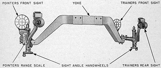
15. The two sight designs of this title are identical except for the bracket details that attach the yoke to the slide. The Mark 33 design applies to Mount Mark 20 type assemblies; Mark 33 Mod. 1 to Mount Mark 22 type assemblies. The assembly, shown in figure 15, is a bar-type open sight arrangement rigidly
54
secured to the slide. It has adjustable eyepieces providing separate off-set arrangement for each line-of-sight for changes in range, but has no provision for deflection setting. The unit comprises: a yoke, sight bar cradles, sight bars, front sight assemblies, ranging bracket assemblies, and eyepiece bracket assemblies. Parts of trainer's and pointer's sights are identical details but of opposite hand.
16. Yoke.-The yoke is a steel casting. It is machined for attachment in transverse alignment on top of the slide. Each end is machined for bolted attachment of the units described in the following paragraph.
17. Sight-bar cradles.-A sight bar cradle is doweled and bolted to each end of the yoke. Each supports a sight bar in a lubricated sleeve which holds the bar parallel to the centerline of the gun. The bar, supporting the front and rear sights, is prevented from turning by a clamping screw in the sleeve and by a chain-secured taper pin passing through the sleeve and engaging a notch in the bar.
18. Front sight.-The front sight assembly consists of a front ring sight, a front sight post, and a front sight holder. The sight post passes vertically through the sight bar, is prevented from turning by engaging lugs, and is clamped by a thumb screw. The holder fastens the sight ring to the post. The ring arrangement consists of vertical and horizontal crossbars suspended within concentric circles, the annular spaces being further subdivided into 30° sectors in each quadrant. The two rings
are alike except that the trainer's horizontal cross-bar carries calibrations designated "speed teeth."
19. Ranging bracket.-The ranging bracket assembly is rigidly mounted by its sleeve to the rear end of the sight bar. This bracket's near vertical portion, inclined slightly forward, is slotted to form a guide track and rotably mounts an adjusting screw with its handwheel and handle on its lower end. To the outboard side of this bracket is fastened a range scale, a flat brass plate with range in yards engraved on its rear face. The graduations beginning at zero are numbered every 1,000 yards through 9,000, intermediate graduations being inscribed as frequently as space permits.
20. Eyepiece bracket assembly.-The eyepiece bracket, a bronze casting, supports at its upper end a rubber headrest and also the rear eyepiece with its cross wires and rubber eye-guard. The bracket's lower end is guided by the ranging bracket's slot, is threaded to the handwheel screw, and carries an index plate.
21. Operation.-Turning the handwheel screw vertically positions the rear eyepiece along its inclined guides, and, at the same time, moves the index plate along the range scale to indicate the range selected. The same setting is made at both the trainer's and the pointer's sights. When the mount is not in use, the sight may be stowed by withdrawing the taper pin from the sight-bar cradle, loosening the clamping screw, turning the sight assembly inboard 90°, and tightening the clamping screw.
FIGURE 15.-3-inch Sight Mark 33 Mod. 1, Left Rear View.
55
Maintenance Instructions
22. General.-These sights do not require disassembly overhaul for appropriate maintenance; all parts are accessible for lubrication and cleaning. Emery paper, lacquer, or paint solvents, or strong detergents must not be used when cleaning the mechanism; such materials will destroy the lacquer and wax-filled calibrations.
23. Operating care.-The deflecting bar and rack, or handwheel drives, or the elevating rack and its indicator strip, if "frozen" or seized must not be forced; distortion of any of these elements will destroy the accuracy of the sight.
24. Lubrication.-The sight assemblies must be lubricated with the lubricants and according to the frequencies specified on the appended lubrication charts.
25. Telescopes.--Gunsight telescopes should be treated with the greatest care in order to keep them serviceable and ready for immediate use. They should never be disassembled unless absolutely necessary and then only by a person skilled in such work. All personnel having anything to do with the telescopes should be familiar with the precautions and instructions for the care of telescopes and specifically the items given below:
(a) The exteriors of the telescopes should be cleaned with a dry cloth only and the cloth should never touch the lenses.
(b) When not in use, glass surfaces must be protected from direct rays of the sun. The variable-density filters must be given special examination frequently to detect deterioration; replace the filter when it becomes defective.
(c) Moisture must not be allowed to remain on a lens or prism surface for any length of time as it causes pitting and this can only be remedied by regrinding the surfaces so affected. Lenses should be wiped off only when necessary. If very dirty or greasy, they should be cleaned with a few drops of alcohol and then dried with a chamois skin, soft linen cloth, or lens paper.
(d) Frequent examinations of all screws about the telescope should be made to see that they are not slacked back. All bolts for securing the telescope should be set up hard before bore sighting.
577305°-44 5
(e) Small particles of dirt visible in the field of view should be tolerated in preference to cleaning the optical surfaces. If, however, the efficiency of the telescope 'is seriously affected by the presence of dirt, the telescope should be cleaned. This should be done only by repair ship or optical shops ashore. Dust or dirt on the crossline lens will appear to be in or near the field of the image.
(f) Rubber guards prevent injury; locate the eye at the proper distance, and keep out stray light. They should not be exposed unnecessarily to extremes of temperature and to the sun's rays. If perspiration or oil accumulates on the eyeguard, it should be removed immediately by wiping with a clean cloth.
(g) Spare eyeguards should be stored in boxes filled with French chalk (talcum powder) to exclude the air, or should be kept under water. A temperature of about 60° F. is the most desirable for storage purposes. To make them pliable they should be steeped in warm water. Rust should be removed immediately by washing guards in soapy water and rinsing in fresh water. Washing soft-rubber eye-guards at frequent intervals will prevent deterioration of the rubber.
(h) During rainy weather leakage of water may occur at eyepiece draw tubes or at the color-filter assembly. This leakage may be controlled by the following procedure, which is graphically illustrated on sketch 99921.
(1) Wax the eyepiece rear lens seat.
(2) Wax under the heads of all screws in the color-filter housing.
(3) Wax the surface between the color-filter housing and cover.
(4) Coat the eyepiece draw tube and color-filter operating shafts with grease; O. S. 1350 will be satisfactory.
(5) Drill a 1/16 inch drain hole through the wall of the color-filter housing at the lowest point.
(i) To obviate the possibility of entry of moisture at the telescope eyepieces it is strongly recommended that all vessels provide canvas covers for eyepiece and color-filter housings. These covers should replace metal covers when stations are manned and should be constructed
56
so as to be removable. It has been the Gun Factory's experience that this simple step will do much to prevent entry of water at eyepieces of exposed optical instruments.
26. Telescope Mark 78 is sealed to withstand a pressure of 150 pounds per square inch and must be tested at this pressure after overhaul or after the telescope seal has been disturbed for any reason. The procedure for emergency testing aboard a submarine is as follows:
(a) Place the telescope to be tested in a suitable pressure cylinder, making sure that the emergency cap for the color-filter knob and the eyepiece cover has been removed.- Seal the cylinder; open the air valve and admit water through the inlet valve until telescope is completely submerged. Close valves and wait 5 minutes before applying pressure.
(b) Run pressure up to 150 pounds per square inch and maintain for one hour. If additional "valuing in" is necessary to maintain pressure, it is evident that the telescope is leaking, and the test should be discontinued and the telescope removed from cylinder.
CAUTION.-When preparing to remove telescope from cylinder do not release pressure suddenly, as this will cause the balsam cement between the eyepiece lenses to crystallize. The pressure is released by slowly opening the drain valve.
(c) Remove the telescope and examine it for leakage. If the only evidence is fogging of the lenses, open the air inlet and outlet valves. If the fog does not disappear within half an hour, then it is evident that the telescope has leaked. If leakage has occurred, the telescope must be disassembled, thoroughly dried, and cleaned.
(d) Considering the work required to put a telescope in serviceable condition after it has flooded, it is essential that all possible precautions be observed in assembling the packings.
(e) After the telescope has been satisfactorily sealed, it should be charged with dry air or dry nitrogen.
27. Recharging telescopes.-In order to maintain the interiors free from moisture the telescopes must be periodically recharged with a dry gas, such as nitrogen or helium, which has been passed through a filter of silica gel. This
recharging should be repeated every 6 months, preferably at the conclusion of overhaul, and always upon reassembly after cleaning or resealing. The interval should never exceed 12 months. There are several methods of drying and recharging optical instruments each of which requires the use of special equipment. These methods are described fully in O. D. 2847.
Adjustments
28. Bore sighting.-The object of bore sighting the mount is to aline the line of sight of the pointer's, checker's, and trainer's telescopes parallel with the axis of the gun, when all parts of the sight are correctly assembled and the sight drums and sight angle bar graduation strip are reading zero range and zero deflection. The theory of this adjustment and the ensuing processes of verifying alinement of bore and lines of sight throughout the range of gun and sight movements is fully discussed in Ordnance Pamphlet 762, Alignment of Ordnance Installation on Board Ship. In such operations, various targets may be used. The target used in bore sighting is often a specially-prepared screen on which are painted vertical and horizontal lines. (The lines are spaced vertically and horizontally at the spacings .of gun axis and lines-of-sight.) This screen may be mounted on the shore or in a boat which is located at a convenient distance. Any object or landmark on the horizon, however, may be used as a target.
29. With the ship in drydock, a batten target is erected a few yards from the muzzle of the gun. Using the bore sight telescope and training the mount slowly in zero gun elevation, a base line is established. A target line is constructed above this base line. With the sight-angle drum set at zero range, the telescopes are moved from left to right in deflection and if correctly installed they will follow the target line. Target lines may be erected perpendicular to the base line and the telescopes elevated or depressed to check the movement of the line of sight in sight-angle motion.
30. Bore Sight Mark 18 is used on these mounts and consists of the following parts:
(a) The telescope holder, a cast steel bracket, bolts directly on to the rear face of the housing
57
and mounts the telescope on the axis of the gun bore.
(b) The cast-aluminum muzzle disc fits into the muzzle of the gun. It is tapered and the exterior surface is engraved by well-defined circumferential lines 1/8-inch apart traced parallel to the face and filled with black wax. In the center of the disk is the 1/16-inch hole used in adjusting the bore-sight telescope.
(e) The Telescope Mark 8 Mod. 6 is used on this assembly. A complete description of the construction, and instructions for the care and adjustments necessary for the Mark 8 type telescopes will be found in O. P. 483.
31. Preparation for bore sighting.-Preliminary to the bore sighting routine outlined in paragraph 32, check the following:
(a) Examine the pointer's, checker's, and trainer's telescopes to see that they are clean, properly focused, and that the crosslines are clearly visible.
(b) See that the gun is in zero elevation, and that the sight drums and elevating-rack scale are in zero position for sight angle and deflection.
(c) Insert the muzzle disk in the muzzle of the gun, tapping it lightly to match the annular engravings with the muzzle face.
(d) Open the breech of the gun by means of the hand operating mechanism and secure the spring as described in chapter II to retain the breechblock in its lowered position, thus preventing its closing.
(e) Attach the telescope-holder bracket to the housing and screw the telescope into the center mounting in the bracket. Adjust the telescope crosslines until they are centered in the hole in the muzzle disk; then tighten the adjusting screws. The line-of-sight through the boresight telescope will then be coincident with the axis of the bore of the gun.
(f) Remove the muzzle disk and focus the telescope on the target as required, noting that there is no parallax.
32. Routine check of lines of sight and bore alinement.-With the bore sight installed as described in paragraph 30 and with the preparations of paragraph 31 complete, proceed as follows using batten or calibrated screen-type target.
(a) To reduce parallax and to centralize the eye in the telescope, diaphragms or disks having the smallest practical drilled peep hole in exact center should be used in the telescope eyepieces, in conjunction with the rubber telescope eye-guards.
(b) With the sight set at 500 mils deflection and 0 minutes sight angle, position the mount so as to bring the bore sight crosslines on the bore sight target. Adjust the telescopes in the holders or adapters so that the crosslines in the pointer's, trainer's, and checker's telescopes fall on their respective target crosslines. Also check the alinement of the open sights at this time.
(c) Train the mount to the right an amount so that when the lines of sight are deflected their design limit to the left, the telescope lines of sight again fall on the targets. The vertical shaft of the horizontal crossline of any telescope should not exceed an angle of one minute, as indicated by the graduated lines on the targets. Bring the mount and sight back to their original positions and repeat this test in the opposite direction.
(d) Again set the mount so that the bore sight and telescope crosslines fall on their respective target crosslines. Elevate the gun 30° (the lines of sight should remain on plumb lines during this operation). Depress the sight until the telescope lines of sight again fall on the targets. The horizontal shift of the vertical crossline of any telescope should not exceed an angle of one minute as indicated by the graduated lines on the targets.
(e) The following operations will ascertain presence of any excessive lost motion in the azimuth gear: Deflect the lines-of-sight well to the right, then bring them slowly back, without reversing the direction of handwheel rotation until the vertical crosslines in the telescopes fall on their respective target crosslines. Note the deflection reading. Run the lines of sight well to the left, then bring them slowly back, without reversing the direction of handwheel rotation, until the same deflection reading is obtained. The horizontal shift of the vertical crosslines in the telescopes should not exceed an angle of one minute as indicated by the graduated lines on the target.
(f) Replace the muzzle disk and check to insure that the bore sight is still coincident with
58
the axis of the bore. Upon completing this verification the gun may be considered properly bore sighted.
33. Observed errors and correction.-When the ship is at sea, all errors discovered in the sight, together with their causes, should be recorded. Bore sighting and readjustment should be made as soon as possible. When the sight is tested during an overhaul period, sight errors should be traced and repaired by standard shop procedure before leaving port. After repair, the sight must be rechecked. The total error in the sight shall not exceed one minute in either elevation or deflection.
Disassembly and Assembly
34. Disassembly is similar for all modifications of the Mark 16 sight. The procedure for disassembly of Sight Mark 16 Mod. 8 is described below:
(a) The counterweight must first be unbolted and removed from the slide before the sight assembly can be dismantled.
(b) Dismantle the open sights and telescopes after the sight has been set at a near-horizontal and mid-deflection position. Remove the azimuth stop screw.
(c) Move the yoke to the left until the azimuth pinion clears the azimuth rack and the yoke forward bearings clear the rocker guides; then lift the yoke off the rocker-pivot pin.
(d) Remove the four azimuth drum cover screws, and remove drum cover.
(e) Withdraw the four machine screws and clamping disk; then remove the azimuth drum.
(f) Withdraw taper pin and disassemble drum disk.
(g) Disassemble drum pinion and shaft, and the azimuth wormwheel.
(It) Remove the lower elevation stop screw and dismantle the sight bar from the sight bracket.
(i) Withdraw the two top-screw bolts and the two rear-screw bolts, and disassemble the deflection head and the deflection rack and rack rivets. Withdraw the two dowels from the sight bar.
(j) Move the elevating rack upward and out of engagement with the elevating handwheel bracket.
(k) Withdraw the four securing bolts of the elevating handwheel bracket and remove the bracket from the gun slide.
(l) Withdraw the four sight angle drum cover screws and remove drum cover.
(m) Withdraw the four machine screws, the clamping disk, and remove the sight-angle drum.
(n) Disassemble the elevation handwheel worm and wormwheel; unbolt and remove the cover from the elevating and azimuth gear bracket.
(o) Remove the elevating shaft and pinion. Remove the rocker from the slide.
35. Reassembly is the reverse of the disassembly procedure.
36. Sight installation.-The following is a description of the procedure and sequence of operations necessary to install any Sight Mark 16 modification on one of the subject mounts. Refer to plate 23, chapter XII, for crane sling arrangement. Drawing numbers referred to are details of the Mark 16 Mod. 8 and Mod. 13 sight, as typical of the two general classifications of sight assemblies covered in this text.
(a) Clean sight thoroughly, removing all dirt and grease.
(b) Check all mating and working surfaces for burrs.
(c) Slush all working surfaces on the sight with Ordnance Bearing Compound, O. S. 1350, and apply Gun Slushing Compound, O. S. 627, on the bearing surface between elevating and azimuth gear bracket and slide before this assembly is made.
(d) Assemble sight angle bar and deflection bar in elevating and azimuth gear bracket.
(e) Place elevating and azimuth gear bracket on slide and pull bolts up snug, not tight.
(f) Assemble elevating gear rocker (2364311) and pins (236431-2) on slide.
(g) Refer plate 23. Assemble yoke on elevating gear rocker and deflection bar. Care must be exercised when assembling yoke to rocker that the pivot on the rocker does not damage the bushing (236431-3) in the yoke.
(h) After the yoke is assembled to the deflection bar, turn down stop screw (12-Z--4101) into slot in the rear of the deflection rack (on 3-inch Sight Mark 16 Mod. 8) or assemble
59
the azimuth stop details, drawing number 241900 as shown in the right hand side of section S-S-S, drawing number 241613. (For 3-inch Sight Mark 16 Mod. 13.)
(i) Try the sight in deflection and elevation. If the operation is satisfactory draw the bolts on the elevating and azimuth bracket up tight. Try the sight in deflection and elevation again for final check on satisfactory operation.
(j) Center the sight azimuth drum with respect to the slot in the deflection rack.
(1) With the stop screw or azimuth stop assembly in position, run the yoke as far to the right as it will go and set the azimuth drum at 700 mils (3-inch Sight Mark
16 Mod. 8) or 800 mils (3-inch Sight Mark 16 Mod. 13).
(2) Run yoke as far to the left as it will go and the azimuth drum should read 300 mils for the Mod. 8 sight and 200 mils for the Mod. 13 sight.
(3) In the event that the above is not the case, due to clearances, center the azimuth drum with respect to the maximum stop position.
(k) Set zero of angle of departure and range strip opposite index lines of the elevating and azimuth gear bracket and adjust the sight,elevation drum to read zero opposite the index line on elevating and azimuth gear bracket.
60
This page is blank.
61
CHAPTER VII
ELECTRICAL INSTALLATION
3-INCH FIRING AND LIGHTING CIRCUITS MARK 5 MODS. 5 TO 7, 11 TO 13, 16 TO 27, INCLUSIVE, AND MARK 10
General Description
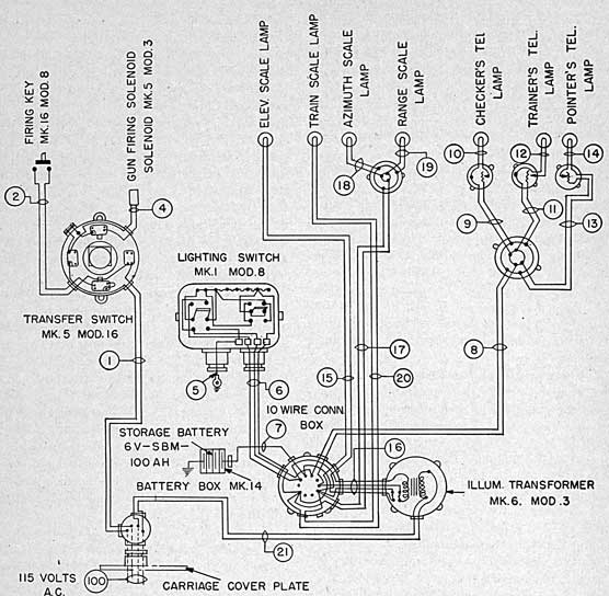
1. All 3-inch mount assemblies described in this book, with exception of mount assemblies for submarine emplacement, include electrical equipment installations for firing and for battle illumination. Some arrangements also include circuits for communication and fire control. The units provided for the respective mount assemblies are designated in the Index of Mount Assemblies, appendix I. They comprise the firing and lighting circuit designs indicated in the title. These designs vary according to number of circuits and differ as to details of assembly or equipment.. According to circuit functional arrangements they comprise three design types.
(a) Firing, lighting and oral communications circuits.-Firing and Lighting Circuits Mark 5 Mods. 5, 6, 7, 11, 12, 13, comprise a design group with similar functional arrangements. These provide for firing, battle illumination and telephone communication.
(b) Firing, lighting, fuse setting and oral communications.-Firing and Lighting Circuits Mark 5 Mods. 16 to 27, inclusive, comprise a design group with similar functional arrangements.. These provide for firing, battle illumination, fuze setter synchro connection and telephone communication.
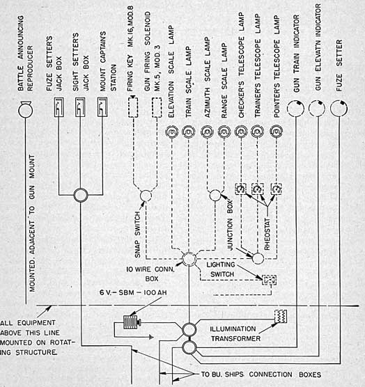
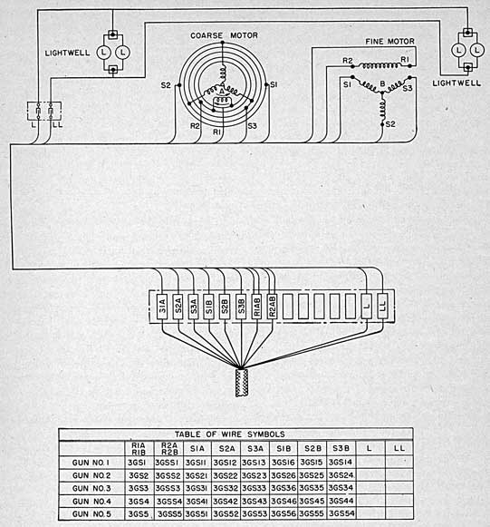
(c) Firing, lighting, and fire control.-Firing and Lighting Circuit Mark 10 is a design type that includes all of the features of the second group and in addition provides: A remote-firing feature in the firing circuits, and synchro circuits and lighting circuits for gun train indicator, gun elevation indicator, sight-angle receiver, and sight deflection receiver. Both the firing and the synchro circuits connect
to the ship's gun-director system or its target-designator system by fire-control circuits.
2. Design differences.-The firing and lighting circuits have principal differences as indicated in the subparagraphs following:
(a) Firing and Lighting Circuit Mark 5 Mod. 5.-This assembly is designed for 115-volt A. C. with firing circuit connected direct and lighting circuit transformed to lower voltage. Battle illumination comprises shielded support light at elevation and training indicator points, interior bulb illumination of azimuth and range-sight drums, and crossline illumination in all telescopes. The assembly is designed for installation on Mount Mark 20 modifications.
(b) Firing and Lighting Circuit Mark 5 Mod. 6.-Same as the Mark 5 Mod. 5 design except that the firing circuit is planned for 110-volt D. C. supply and the system omits lighting circuit transformer. Lighting circuit is supplied from 6-volt battery. The design is for installation on Mount Mark 20 modifications.
(c) Firing and Lighting Circuit Mark 5 Mod. 7.-Same as the Mark '5 Mod. 5 and Mod. 6 arrangements for Mount Mark 20 modifications except that the firing circuit as well as the lighting circuit is supplied from 6-volt battery.
(d) Firing and Lighting Circuit Mark 5 Mods. 11,12, and 13.-These designs are similar respectively to the Mark 5 Mods. 5, 6, and 7, but are adapted for installations for Mount Mark 22 and Mark 22 modifications.
(e) Firing and Lighting Circuit Mark 5 Mods. 16,17, and 18.-These designs are similar respectively to Mark 5 Mods. 5, 6, and 7 designs but with added provision for fuze setter dial
62
PLATE 14 - FIRING AND LIGHTING CIRCUIT MARK 5 - MOD. II 3-INCH GUN MOUNT MARK 22-RIGHT FRONT VIEW
63
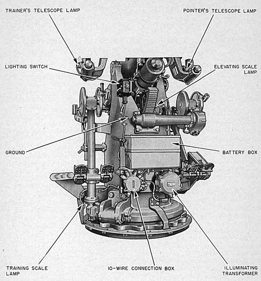
FIGURE 16.-Firing and Lighting Circuit. Mark 5 Mod. 11.
illumination. They are adapted for installation on Mount Mark 20 modifications.
(f) Firing and Lighting Circuit Mark 5 Mods. 19, 20, and 21.-These designs are similar to the Mark 5 Mods. 16, 17, and 18 designs, respectively, but are adapted for installation on Mount Mark 22 and Mark 22 modifications.
(g) Firing and Lighting Circuit Mark 5 Mods. 22, 23, and 24.-These designs are similar to Mark 5 Mods. 5, 6, and 7 designs, respectively, with added provision for fuze setter dial illumination. They are adapted for installation on Mount Mark 20 modifications.
(h) Firing and Lighting Circuit Mark 5 Mods. 25, 06, and 27.-These designs are the
same as the Mark 5 Mods. 22, 23, and 24, respectively, but are adapted for installation on Mount Mark 22 and Mark 22 modifications.
(i) Firing and Lighting Circuit Mark 10.-This design is similar to the Mark 5 Mod. 25 design with the added fire control features indicated in paragraph 1 (c) and with a different gun firing solenoid. The latter change provides a design which operates on a lower current line demand. The battery is located off the mount.
Detail Description-Firing Circuits
3. Remote and local firing.-Two systems are provided for electrical control of firing: A remote control system (for those mounts with
64
train and elevating gun attachments) by which the guns are fired from any one of the ship's directors ("director fire"), the particular director being chosen by the setting of the selector switches in the plotting room; and a local or "pointer fire" control by a firing key on the handwheel. Each director has three firing keys-officer's, pointer's, and trainer's-all connected in parallel so that firing may be controlled by any one. The circuit is normally energized by ship's 110-volt D. C. or 115-volt 'A. C. supply. In case of failure of ship's supply the circuit is energized by an emergency
D. C. supply from 6-volt storage battery. Switch over from one supply to the other is made by a transfer switch located at the gun mount pointer's station. The firing system does not include firing-stop mechanism on any of the mounts. Premature firing is normally prevented by the mechanical design of the firing-pin assembly.
4. Components of the firing circuit.-The several firing circuit design arrangements include the following described principal units.
(a) Firing keys.-The pointer's Firing Key Mark 16 Mod. 8 is a pistol grip type mounted on the pointer's right handwheel. It includes a latch for locking into closed position. The design is shown on' drawing number 165694. The director is equipped with Firing Key Mark 16 Mod. 9 which is the same key as the pointer's without the latch feature.
(b) Storage battery.-The storage battery is a 6-volt, 100-ampere-hour type located on the "front of the mount on merchant installations, but below decks on all service emplacements.
(c) Transfer Switch Mark 5 Mod. 16.-This unit is a rotary-type snap switch of standard design. It is enclosed in a heavy aluminum-alloy case. Its four positions are marked: Off, local battery, off, motor generator. The design is shown on drawing number 231598.
(d) Gun Firing Solenoid Mark 5 Mod. 3.-This unit, located on the slide cam plate as shown on plate 1, is a percussion fire actuating device. As the circuit is closed in the firing key, the solenoid is energized and the plunger snaps forward and contacts a lug or trigger, forcing it to rotate beyond its release point, thus firing the gun.
(e) Gun Firing Solenoid Mark 14.-This
unit, mounted on an extension support secured to the top of the slide cam plate, is also a percussion fire actuating device, but is adapted for a design variation of the firing mechanism. It is a 120-volt, 60-cycle unit designed for low current operation. The direction of the plunger movement is opposite to that of the Mark 5 Mod. 3, thus upon closure of the firing circuit the plunger snaps back into the unit dragging the upper end extension of the trigger forward and tripping the sear.
5. Operation.-Firing is effected by the action of the solenoid on the trigger. The gun is cocked for fire as soon as the breechblock closes. The sear may be tripped either mechanically through the foot-firing linkage or electrically by the thrust of the solenoid plunger on the trigger. Firing takes place when the circuit is closed by either the pointer's firing key or, in director installations, by firing key at the director. Details of operation of the two types of system arrangements are indicated in the subparagraphs following.
(a) For director fire.-The transfer switch is positioned to energize the circuit from the firing transformer. The pointer's firing key is next latched closed. After the breech has closed the gun will fire when any key in the director is closed. It is not possible to utilize the battery for director fire.
(b) Pointer fire.-In case of failure of the ship's power supply, the pointer's key must be unlatched, the transfer switch set to battery supply, and the firing controlled locally by the pointer's key.
Lighting Circuits
6. The lighting circuits provide illumination by small lamps in shielded enclosures at all instruments and controls used during battle. It also includes independent crossline illumination control for each telescope by a rheostat in the lamp lead. The circuit uses 6-8-volt lamps and has current supply from either of two sources: The ship's regular 115-volt A. C. line by step-down illumination transformer, or from a 6-volt storage battery. Selection of power supply is effected by the lighting switch.
7. Components of the lighting circuit.-The description and location of the lighting-circuit components are as follows:
65
(a) Mazda 64 lamp is used, all single-filament, bayonet-socket 6-8-volt type, located as shown on plate 14 and figure 16.
(b) Lamp Sockets Mark 9 are used throughout.
(c) Rheostat Mark 8 Mod. 15 controls the telescope-crossline illumination. Three are used, one each for the pointer's, checker's and trainer's telescopes, located as shown on plate 14 and figure 16. Each rheostat is a 0-25-ohm, 6-volt variable resistor of nichrome wire on a Bakelite ring.
(d) Illuminating transformer is a 75-watt; 60-cycle single phase illuminating transformer,
with 115-volt primary and 6-volt secondary. It is housed in a watertight drum-shaped case mounted below deck whenever possible. Its primary leads are supplied through a connection box from the ship's 115-volt supply. Its secondary feeds a tank of seven 5-ampere fuses within the transformer housing; these protect the various circuits against short circuit.
(e) Lighting Switch Mark 1 Mod. 8 is a combination of two snap switches in one housing, one a transfer switch to connect the lighting circuit to either transformer or battery supply, the other a dimming switch with Normal and Dim positions. In the Dim position, it
FIGURE 17.-External Wiring Diagram Mount Mark 22 Mod. 4.
66
introduces a resistance which reduces all except the telescopes to a low illumination. Included also in the switch housing is a resistance equalizer so connected that there will be equal dimming whether the circuit is on battery or transformer supply.
(f) Fuses are provided only on the lighting circuit of the 115-volt A. C. installations. These fuses are located within the watertight case which houses the illuminating transformer.
Fire Control Circuits
8. The ship's gun director system is connected by the fire control circuits for these mounts to their annunciators or to the synchro motors of the gun elevation indicators, gun train indicators, sight angle receivers, sight deflection receivers, and fuze setters.
Communication Circuits
9. The communication circuits for those mounts so equipped include a battle telephone system and an announcing reproducer as described below.
10. Battle telephone system.-The ship's battle telephone system provides communication between the mount and the fire-control stations (director, plotting room, etc.). It has branches on the mount at the sight setter's, fuze setter's, and gun captain's station. Each branch has a jackbox outlet to the respective station and the operator at each station is furnished a headset with an extension cord which plugs into the jackbox. The headset comprises a pair of receivers and a transmitter. The battle telephone system operates by electrical transmission of voice impulses but is energized only by voice power. The stations are arranged to be served by the primary system which, normally, connects all stations through a switchboard-control exchange located in the plotting room.
11. Battle announcing reproducer.-Battle orders are received at the mount also by audible signals or verbal orders received over the battle-announcing reproducer. This is a powerful loudspeaker located adjacent to the mount and is part of a public-address system which connects the directors and the plotting room with all mounts. The conventional auditory
battle-order signals are generated by this system and transmitted to the mounts by closing an appropriate contact maker in the director. Verbal orders are sent out to the mount through a transmitter in the director. Each mount's reproducer is connected to the appropriate director by switching arrangements in the plotting room.
Maintenance Instructions
12. The primary difficulties to be encountered in electrical equipment are insulation failures due to an accumulation or absorption of moisture, and loosening or breaking of connections due to shock. Precautions and remedies for moisture troubles are detailed in paragraphs below. Trouble caused by moisture will be quickly detected by the daily insulation check. Troubles due to loose or open connections will become noticeable through faulty operation or complete failure of the equipment concerned. Connection looseness will manifest itself in local heating at the panels, and the cause of such heating should be investigated. Heating is, in general, a good indication of trouble.
13. Firing circuits.-It cannot be too strongly emphasized that the firing circuit is a low-resistance circuit, designed to carry heavy current at low voltage. Insulation of the ungrounded portion of the circuit must be checked regularly and frequently. Flexible cable, particularly the handwheel loop portion, must be tested frequently to insure that no breaks exist, resulting in intermittent flow of the current. These will cause misfires when the cable is stretched or twisted.
14. Firing-circuit inspection.-In addition to the above tests the firing circuit should be examined frequently for kinks which lead to internal breaks, worn insulation, oil soaked insulation, and elevation loops that may catch on some projection of gun or mount.
15. Fuze failure is proof of trouble in the circuit. Before replacing a blown fuse, check and remove the cause of the overload. Fuses should never be replaced with those of higher ampere rating, because the "heavier" fuse in conducting higher currents fails to protect the wiring and equipment of the circuit. Consult the wiring diagram, if available, for the proper amperage of the fuse to be used.
67
CHAPTER VIII
DIRECTOR GEAR 3-INCH TRAINING GUN ATTACHMENT MARK 7 AND MARK 7 MOD. 1 3-INCH ELEVATING GUN ATTACHMENT MARK 1 GUN TRAIN INDICATOR MARK 23 MODS. 2 TO 12, INCLUSIVE, GUN ELEVATION INDICATOR MARK 21 MOD. 4 SIGHT DEFLECTION RECEIVER MARK 1 AND MARK 1 MOD. 1 SIGHT ANGLE RECEIVER MARK 1
General Description
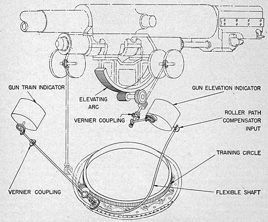
1. The assemblies indicated in the title comprise gun mount mechanisms and instruments for director controlled emplacements. The mount assemblies on which they are installed are indicated in the Index of Assemblies, appendix I. The training and elevating gun attachments are separate arrangements of shafts and gears which are mounted on the right and left sides of the carriage respectively, as shown on plate 15. They function to transmit the angle of train and elevation from the worm shaft of the manual drive in each case to their respective indicators. The indicators, in addition to receiving the existing angle of gun train or gun elevation mechanically from their respective handwheels, receive the desired angle of gun train or elevation electrically from the gun director or the target-designation transmitter. The sight-deflection receivers and the sight-angle receiver are not actuated mechanically but electrically only by the target-designation transmitter. These transmitted angles may be read from the indicators' and receivers' dials.
Training Gun Attachments
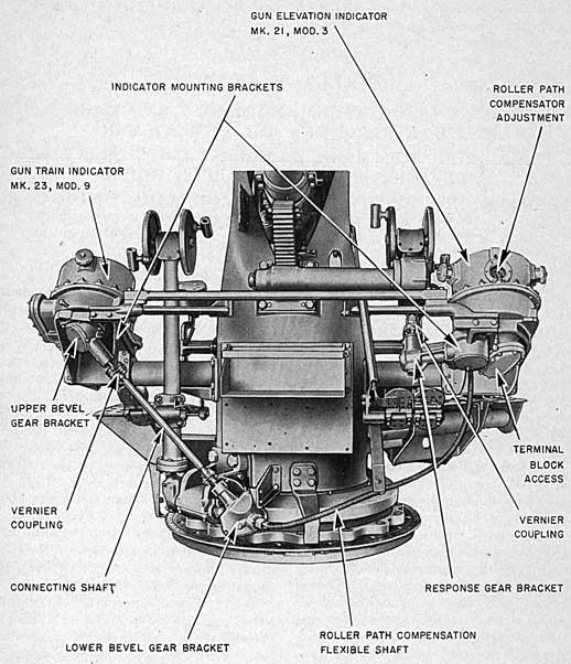
2. Training Gun Attachment Mark 7.-The training gun attachment is mounted on the right side of the carriage and conveniently position's a gun-train indicator forward and to the right of the trainer's handwheels. (See fig. 18.) This attachment consists mainly of a
support bracket, an indicator-mounting bracket, an upper bevel-gear bracket, a connecting shaft, and a lower bevel-gear bracket. Through the connecting shaft, bevel-gear brackets, and train-worm shaft the existing train angle is transmitted from the hand wheels to the indicator.
3. The Training Gun Attachment Mark 7 Mod. 1.-The modified attachment differs from the Mark 7 design principally in the redesign of the upper bevel gear bracket. The bracket is separated into two elements, designated upper bevel-gear bracket and upper shaft-mounting bracket which are joined by four bolts. The shaft mounting bracket carries the bearings which mount the short bevel gear shaft. This arrangement permits ready alignment of the bevel gears by shimming between the two elements of the bracket and between the two parts of the indicator input-shaft gear.
4. Lower bevel gear bracket.-The lower bevel gear bracket provides engagement for the training gun attachment linkage with the rotating portion of the mount, by means of an Oldham self-aligning coupling between the training worm shaft of the mount manual drive and the lower bevel gear pinion shaft. (See ch. IV, par. 5.) This pinion shaft is ball bearing mounted in the lower bevel-gear bracket and carries the pinion gear keyed to it and located within the bracket. The forward end of this shaft couples with a flexible shaft to the gun elevation indicator on the left side of the
68
PLATE 15 - 3-INCH GUN MOUNT MARK 22, MOD 4 FRONT VIEW
69
FIGURE 18.-Training Gun Attachment Mark 7.
mount. Meshing with the pinion is the mating bevel gear keyed to the lower end of its shaft which extends upward at an angle of 58° with the pinion shaft and projects out of the bracket. These shafts and gears are housed in a cast bracket which is mounted on and secured to the forward end of the training-worm bracket by four 5/8-inch bolts. Additional support is provided by a shaped strut of steel plate, securing this bracket to the carriage.
5. Upper bevel gear bracket.-The upper
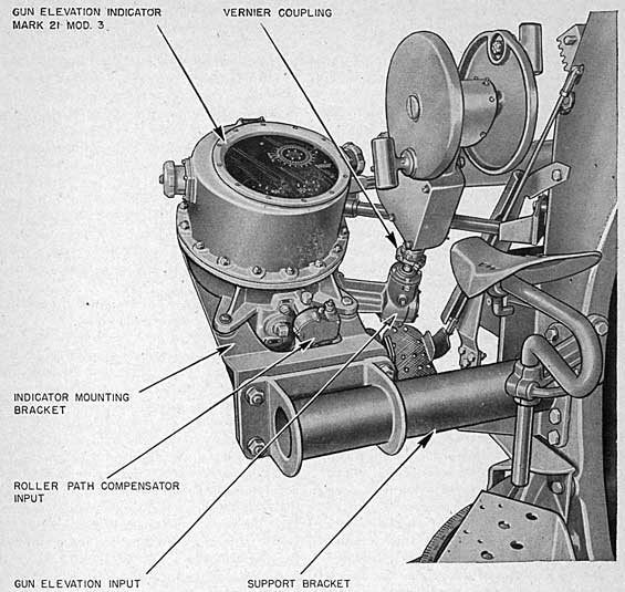
bevel gear bracket serves merely to mount and house the upper end of the mechanical shaft linkage. This consists of a set of bevel gears mounted within the bracket which connect the indicator unit with the connecting shaft between this bracket and the lower bevel-gear bracket. The bracket bevel gear shaft is connected to the connecting shaft by a vernier coupling. The bracket is mounted on and secured to the underside of the indicator mounting bracket by five 3/8-inch bolts.
70
6. Support bracket.-The support bracket in a weldment of 3/8-inch steel plate and 4.0-inch pipe. It is designed to provide support and mounting for the upper, bevel gear bracket and the gun train indicator. The inboard end of this bracket is secured to the right face of the mount carriage by six 3/4-inch bolts. The bracket extends outward from the carriage to present a vertical bolting pad facing forward.
7. Indicator bracket.-The indicator mounting bracket is designed to furnish mounting for the indicator unit and the upper bevel gear bracket. It is a cast bracket mounted on and supported by the support bracket to which it is secured by four 3/4-inch bolts.
Gun Train Indicators
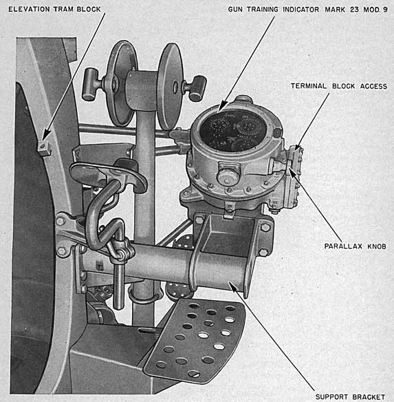
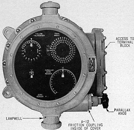
8. Train indicator.-Gun Train Indicators Mark 23 Mods. 4-12 receive gun train orders and train parallax orders electrically from the
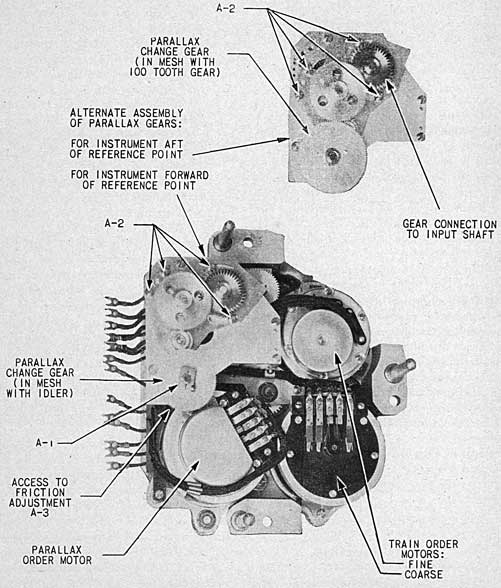
controlling director. The modification numbers of these indicators are determined by the diameter of the particular parallax change gear used to suit the location of the mount with respect to the controlling director. These indicators receive the existing gun train mechanically from the train worm shaft, and receive parallax correction from a manually operated knob on the instrument case. Dials are provided for indicating gun train and parallax correction and for synchronizing these quantities with the orders.
9. Gun Train Indicators Mark 23 Mods. 2, 3 are similar to the Mark 23 Mod. 4 design except that the parallax unit is blocked out. These indicators receive existing gun train mechanically in the same manner as the other designs, but they receive gun train orders electrically from the target designation transmitter.
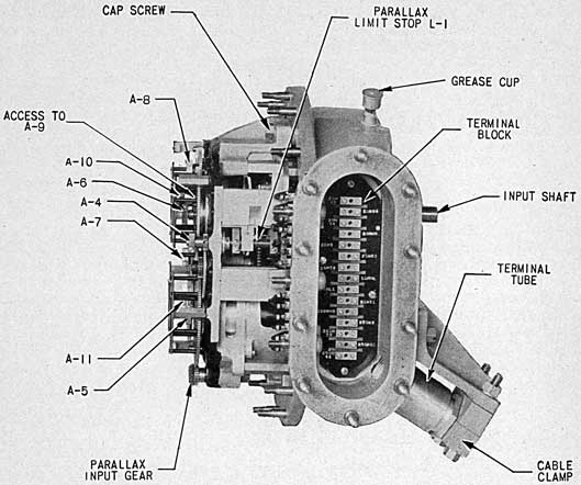
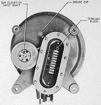
10. Cases.-The cases of the indicator units are water-tight and have drain plugs at the
FIGURE 19.-Training and Elevating Gun Attachments, Schematic Diagram.
71
FIGURE.-Gun Train Indicator Mark 23 Mod. 1.
lower ends. Windows in the covers are fitted with nonshatterable glass.
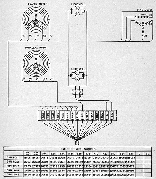
11. Electrical connections.-The ship cables are brought through standard terminal tubes into junction boxes cast integrally with the indicator cases. The rotors of the synchro motors are energized from the same 115-volt, 60-cycle fire control supply circuit that is connected to the transmitting units. The stators are energized from synchro generators in the gun director or the target designation transmitter. Current for lighting is received from an illumination transformer.
12. Illumination.-Illumination of dials is as required for instruments in exposed locations. Light is obtained from one or more lampwells, each containing two Mazda-type 64 double-contact 6-8-volt lamps, connected in parallel. The lampwells have covers which can be readily unscrewed to remove or install lamps.
577305°-44-6
Removal of a Iampwell cover does not impair the watertight seal of the mechanism case, as the lamp housing is flange and gasket mounted in the case and the inner end is sealed by a translucent diffusion disk. By unscrewing the cap of the lampwell unit, the twin lamp mounting may be lifted clear for the replacement of lamps. The light shines through the graduations and figures which are cut through the dials and face plates and are filled with translucent lacquer.
13. Description indicator mechanism.-Gun train order is received electrically by two synchro motors. A shaft extends through the bottom of the case for the input of existing gun train. (See fig. 26.) One revolution of the train input shaft represents 10° gun train. Increasing gun train causes clockwise rotation of the shaft as viewed from the shaft extension end. The coarse motor, type 5B, is so mounted that its stator is rotated by the train handwheel
72
through a differential; one revolution of the stator represents 360° of gun train. A zero-reader-type dial is mounted on the rotor; one revolution represents 360° of gun-train order. (See fig. 20.) The fine motor, type 5F, is mounted with the stator stationary. Its rotor carries a dial for follow-the-pointer operation; one revolution represents 10° of gun-train order. Concentric with the fine-rotor dial is the index-ring dial, driven, like the stator of the coarse
motor, by the output of the differential, but at a gear ratio such that one revolution of the dial represents 10° of gun train. By turning the handwheels until the zero-reader pointer is matched with its fixed index, and the index on the follow-the-pointer ring dial is matched with the pointer on the rotor dial, the gun is trained to the correct angle.
14. Graduations on both coarse and fine rotor dials, together with the designations, left and
FIGURE 21.-Gun Train Indicator Mark 23 Mod. 3 Wiring Diagram.
73
right, on the fine dial, indicate the direction and amount of any deviation of existing gun train from the correct angle. These graduations can also be used for calibration and testing. The follow-the-pointer rotor dial is graduated to indicate 5° each side of the pointer: up to 2° in 5' steps, and from 2° to 5° in 30' steps. The zero-reader dial is graduated in 2° steps for 10° each side of the pointer.
15. A 5B synchro motor, used to receive train parallax order, is mounted so that the stator is rotated by the parallax knob on the outside of the case. Mounted on the stator, and turning with it, is a- ring dial graduated to read in 10' steps from 0° to 12° in both directions. The rotor carries the parallax-zero-reader dial and pointer. Reading the ring dial against this pointer shows the parallax order computed for 100-yards base length. When the parallax knob is turned to bring the pointer in line with the fixed index, a quantity proportional to the parallax order is combined in the differential with gun train from the train hand-wheels. One revolution of the parallax knob represents 6° parallax correction (referred to 100-yard base). Counterclockwise rotation of the knob introduces increasing parallax correction in an instrument mounted on a gun forward of the reference point and decreasing correction in one on an after gun. Figure 25 shows the alternate methods of assembly of the parallax gears to accomplish this reversal. The percentage of the order thus introduced is equal to the ratio of the actual base length to 100 yards, and therefore represents the proper parallax correction for that base length. A parallax change gear is used to suit the actual base length for each instrument, the design being such that the number of teeth in the gear is equal to the base length in yards.
16. The parallax order transmitted from the ballistic converter unit of the gun director is computed for guns mounted forward of the reference point. For such guns, the instrument is assembled with an idler gear in mesh between the change gear and the 100-tooth gear, as shown in the rear view of the mechanism. For guns aft of the reference point, it is assembled as shown in the small insert on figure 25 with the change gear in mesh with the 100-tooth gear, thereby reversing the correction.
17. The parallax correction, introduced as explained in paragraph 15, offsets the train zero-reader and follow-the-pointer dials, and requires the trainer to rematch them by means of his handwheels. By this operation he trains the gun to the correct angle,, that is, the algebraic sum of gun train order and parallax correction.
18. The output of the differential rotates the train angle dials also. These dials indicate the existing gun train only when the parallax correction is zero. They indicate the train order when the follow-up dials are matched with their respective indexes. The coarse train angle dial is graduated from 0° to 360° in 10° steps. The fine dial is graduated in 5' steps; one revolution represents 10°.
19. Operation.-The procedure of operating the gun train indicator is as follows:
(a) Turn the parallax knob so as to keep the parallax-zero-reader dial pointer in line with the fixed index. This must be done continuously while the instrument is in use.
(b) Turn the train handwheels so as to bring the pointer on the zero-reader dial in line with the fixed index for an approximate setting.
(c) Turn the handwheels so as to keep the index on the follow-the-pointer ring dial continuously matched with the pointer on the inner dial. If the inner follow-the-pointer dial rotates clockwise with respect to the ring dial, the word left is carried toward the index mark on the ring dial. This indicates that the gun is off to the left, and it must therefore be trained right in order to synchronize the dials. Counterclockwise rotation carries the word right toward the index mark which, of course, means the reverse.
Elevating Gun Attachment Mark 1
20. The elevating gun attachment is mounted on the left side of the carriage and conveniently positions a gun elevation indicator forward and to the left of the pointer's handwheels. (See fig. 22.) This attachment consists mainly of a response bevel gear bracket, an indicator mounting bracket, a support bracket, a roller path compensation worm and wormwheel bracket, and a flexible shaft which will be described below. Through the response bracket existing gun elevation is mechanically transmitted from
74
FIGURE 22.-Elevating Gun Attachment Mark 1.
the handwheels to the indicator; through the flexible cable and compensation bracket existing gun train is mechanically transmitted from the lower bevel gear bracket to the indicator.
21. Response gear bracket.-The response-gear bracket houses a set of bevel gears which transmit the angle of elevation from the hand. wheel bracket to the indicator unit. The response-connecting shaft projects from the inboard portion of this bracket to be connected to the elevating-worm shaft by a vernier coupling and an Oldham coupling. This response shaft carries a pinion which meshes with a bevel gear keyed on the end of the response cross shaft. This cross shaft extends through the
transverse tube of the bracket and projects into the indicator mounting bracket.
22. Indicator bracket.-The indicator mounting bracket is a casting which provides an inclined bolting pad for mounting the gun elevation indicator, and houses a set of bevel gears which transmit the gun elevation from the response cross shaft to the indicator shaft. This bracket is mounted on and secured to the vertical pad surface of the support bracket, and is secured to it by four 3/4-inch bolts.
23. Support bracket.-The support bracket is a weldment fabricated from steel plate and a length of 4.0-inch steel pipe. It is secured to
75
the left side of the carriage by four 3/4-inch bolts and positioned by two 3/4-inch dowels. The bracket extends horizontally out from the carriage to provide a vertical bolting pad to support the indicator mounting bracket.
24. Compensation bracket.-The roller path compensation worm and wormwheel bracket is a casting mounted and secured to the underside of the indicator unit. This bracket is connected by a flexible cable across the front of the carriage to the lower bevel gear bracket of the training gun attachment. ( See par. 4.) When the mount trains, the turning flexible shaft within the cable actuates the bracket's worm and wormwheel engagement to rotate the indicator's input shaft.
Gun Elevation Indicator Mark 21 Mod. 4
25. Function.-This instrument receives gun elevation orders electrically from the gun director or the target-designation transmitter. It receives the existing angle of gun elevation and of gun train mechanically from the elevating
and training drives. A roller-path compensator, driven by gun train, is included in the instrument. This device computes and applies a correction to gun elevation to compensate for the inclination of the roller path. Dials are provided for indicating gun elevation and for synchronizing it with the order.
28. The effect of inclination of the roller path of the gun with respect to the reference plane is to cause a sinusoidal variation in true gun elevation as the gun is trained. This variation is computed by the roller-path compensator and introduced into the gun-elevation gearing differential. The compensator consists of an eccentric pin mounted on a gear rotated by gun train, and operating in a slot in a sliding rack. The movement of the rack is sinusoidal with respect to the rotation of the gear, the extreme movement in either direction being equal to the distance of the pin from the center. This distance, which is adjustable, is made proportional to the inclination of the roller path. A linear scale, graduated in 5' steps, shows the position
FIGURE 23.-Gun Elevation Indicator Mark 21.
76
of the eccentric pin for any roller-path inclination between 0' and 60 minutes. The gear is adjusted with respect to gun train, received mechanically, so that the extreme travel of the rack occurs at the high and low points of the roller path. A dial mounted on the gear is graduated every 5° and indicates the train from the high point when read against a fixed index. Movement of the rack, representing the compensation, is transferred to gearing and is added in the differential to gun elevation from the elevation handwheels.
29. Roller-path compensation, having been combined with the gun-elevation input in the differential as explained above, offsets the zero-reader and follow-the-pointer dials and requires the gun pointer to rematch them by means of his handwheels. The operation results in the gun being elevated to the correct angle: that is, the algebraic sum of gun elevation order and the correction.
30. The output of the differential also rotates the elevation minutes dials. These dials indicate the actual elevation of the gun above its own roller path only when the gun is trained 90° from the high point. They show the gun-elevation order when the zero-reader and follow-the-pointer dials are matched with their respective indexes. The coarse elevation minutes ring dial is graduated from 0' to 7,000' in 100' steps. The fine dial is graduated in 5' steps, one revolution corresponding to 600 minutes. A dial reading of 1,000' represents zero gun elevation.
31. To prevent damage to the instrument's mechanism due to the kick when the gun is fired, there is a safety spring coupling on the input shaft just inside the case. On the shaft connecting with the input shaft, there is a second spring coupling. ( See fig. 29.) When the gun is fired one of the springs is wound up momentarily without driving the instrument gearing. It unwinds immediately, bringing the dials to the correct position. The springs are so heavy that they cannot be wound up by means of the handwheels; consequently they do not cause any lag of the dials in normal operations.
26. Description indicator mechanism.-Gun elevation order is received electrically by two synchro motors. Shafts extend through the
rear and bottom of the case for the mechanical inputs of existing gun elevation and gun train, respectively. One revolution of the elevation input shaft represents 600' gun elevation. Increasing gun elevation causes clockwise rotation of the shaft as viewed from the shaft extension end. One revolution of the train input shaft represents 120° gun train. Increasing gun train causes counterclockwise rotation of the shaft as viewed from the shaft extension end. The coarse motor, type 5B, is mounted so that its stator is rotated by the elevation handwheels through a differential, one revolution of the stator representing 10,800' of gun elevation. A zero-reader-type dial is mounted on the rotor, one revolution of which represents 10,800' of gun elevation order. The fine motor, type 5F, is mounted with the stator stationary. Its rotor carries a dial for follow-the-pointer operation, one revolution representing 600' of gun-elevation order. Concentric with the fine-rotor dial is the index-ring dial, driven, like the stator of the coarse motor, by the elevation handwheels through the differential, but at a gear ratio such that one revolution of the dial represents 600' of gun elevation. By turning the handwheels until the zero-reader pointer is matched with its fixed index, and the index on the follow-the-pointer ring dial is matched with the pointer on the rotor dial, the gun is elevated to the correct angle.
27. Graduations on both coarse and fine rotor dials, together with the designations, low and high, on the fine dial, indicate the direction and amount of any deviation of existing elevation from the correct angle. These graduations can also be used for calibration and testing. The follow-the-pointer rotor dial is graduated in 5' steps to indicate 20' each side of the pointer. The zero-reader dial is graduated in 100' steps to indicate 200' each side of the pointer.
32. Operation.-The procedure of operating the gun-elevation indicator is as follows:
(a) Turn the gun elevation handwheels so as to bring the pointer on the zero-reader dial in line with the fixed index for an approximate setting.
(b) Turn the handwheels so as to keep the index on the follow-the-pointer ring dial continuously matched with the pointer on the inner dial. If the inner follow-the-pointer dial
77
rotates clockwise with respect to the ring dial, the word "low" is carried toward the index mark on the ring dial. This indicates that the gun is too low, and it must therefore be elevated in order to synchronize the dials. Counterclockwise rotation carries the word "high" toward the index mark which, of course, means the reverse.
(c) If the pointer of the zero-reader dial is at any time noticeably out of line with its fixed index, follow items (a) and (b) again in sequence.
Sight-Deflection Receivers
33. Receiver components.-Sight Deflection Receiver Mark 1 mounted by means of an adapter to the Mark 16 Mod. 16 sight's deflection indicator drum cover (see ch. VI, par. 10), indicates electrically the desired angles of sight deflection from the target designation transmitter. The receiver is composed mainly of a casing, a motor, a dial, a terminal block, and two lamps.
34. Casing.-The casing is made in two halves. The inboard half is bolted to the supporting adapter; and is threaded to a packing gland which receives the 10-wire conductor cable. To the outboard half is fastened by screws a frame with a safety-glass dial window, a side cover carrying an air-inlet valve, and on the opposite side a drain plug. By means of the valve and plug moisture may be removed and the interior dried out.
35. Motor and dial.-The synchro motor, a 115-volt, 60-cycle single-phase A. C. unit, is mounted in the outboard casing by a three-point seat and clamp. To the motor is fastened its terminal block. The motor's deflection dial is graduated in increments of 10 mils and numbered counterclockwise every 20 mils from 300 to 700 mils. The dial's graduations and numbers and its peripheral index arrow are cut through and filled with a white, translucent lacquer for illumination from two internally mounted lamps. Between the lamps and the dial a red lucite shield dims the light and causes the inscriptions to appear red.
36. Receiver modification. - Sight Deflection Receiver Mark 1 Mod. 1 is mounted by means of an adapter to the deflection-indicator drum cover of Sight Mark 16 Mod. 15. Except for the fact that the dial is numbered clockwise
to agree with the numbering and rotation of the adjacent drum, this receiver is the same as the Mark 1 receiver.
Sight-Angle Receiver Mark 1
37. This receiver, mounted by means of an adapter to the elevating-indicator-drum cover (see ch. VI, par. 11) of Sights Mark 16 Mods. 15 and 16, indicates electrically the desired sight angles from the target-designation transmitter. In all respects this receiver is the same as the sight-deflection receivers just described except that the dial is graduated in 20-yard increments and numbered every 100 yards from 0 to 1,200 yards.
Maintenance Instructions
38. The training and elevating gun attachments with their indicator and receiver units are to be operated, adjusted, lubricated, and maintained in accordance with the regulations of the Ordnance Manual and the specific instructions following. The gears, shafts, and bearings of these assemblies shall be lubricated according to the frequency, and with the lubricants specified on the lubrication chart. If lubricants other than those specified are used as a temporary substitute, they must be completely removed before lubricating the parts with the correct lubricant.
39. Gun train and elevation indicators.-The glands through which the input shafts enter the indicators have external grease cups. These cups should be kept filled with O. S. 1350. Care should be exercised to avoid excessive lubrication. If too much grease is used it may be forced into the instrument case. A very light film of O. S. 1350 lubricant should be applied to the gearing once a year. Dirt and old lubricant should be removed before the new is applied. For all ball bearings, including those in the synchro motors, use O. S. 1362. Oil bearings sparingly, using not more than one or two drops once a year in each bearing.
40. Should trouble occur with a synchro motor, examine the brushes, brush springs, and slip rings. Remove any dust or foreign matter from the rings with alcohol on a clean, lint-free cloth. Special care should be exercised to avoid injury to the brush rigging and the polished surfaces of the rings. For further information on the care of synchro motors see O. D. 2620.
78
FIGURE 24.-Gun Elevation Indicator Mark 21 Mod. 4, Wiring Diagram.
Testing
41. General.-Simple tests to check the condition of, the circuits and the operation of the indicators and receivers are described below. Such tests should be made daily. If any test proves unsatisfactory, the unit should not be opened until the following conditions have been positively verified.
(a) All circuits are properly connected and energized at the switchboards.
(b) No fuzes or switches are open.
(c) All leads are connected to the correct terminals at junction boxes.
(d) All transmitters are functioning properly:
If all the motors of one type read incorrectly it is probable that the trouble is in the transmitting unit, or in the circuits leading from that unit. Only after the fault has been definitely located in one indicator or receiver should it be
79
opened or the mechanism removed, and then only by qualified personnel. Any adjustments which may have been disturbed by removal of the mechanism, or otherwise, must be restored before replacing the cover.
42. Daily tests-gun train indicator.-Throw the switches so as to connect all gun train indicators to the gun director or the target-designation transmitter. Energize the circuits. Set up in succession 33°, 97°, 150°, 213°, 277° and 300° on the gun train-order-transmitter
dials. Check each indicator for three of these orders as widely separated as the train of the gun will permit. To check an indicator, synchronize the zero-reader and follow-the-pointer dials by turning the gun train handwheels, and read the train angle dials.
43. Daily tests-gun elevation indicator.-Throw the switches so as to connect all gun elevation indicators to the gun director or the target designation transmitter. Energize the circuits. Set up in succession 0, 2800 and 5600
FIGURE 25.-Gun Train Indicator Mark 23 Mod. 1, Rear of Mechanism.
80
minutes on the gun-elevation-order transmitter dials. For each transmitter reading, synchronize the zero-reader and follow-the-pointer dials in each indicator by turning the gun elevation handwheels, and read the elevation minutes dials.
Adjustments
44. Gun train indicator.-To furnish a means of securing a correct relation between the various elements of an indicator, adjustment points are provided. These adjustment points, consisting principally of clamps and couplings, are adjusted initially at the factory or at the time of installation. They should require no further attention unless the mechanism has been damaged or disassembled. Only men thoroughly familiar with the work should be permitted to make any readjustment, and then only when approval has been given by a qualified authority. The procedure for making adjustments on the indicators of the title is described below. This procedure must be followed rigidly, and adjustments must be made in the order in which they are given. When one adjustment is changed, all succeeding adjustments must be checked also.
45. At the time of installation, it is necessary to adjust the dials of each indicator with respect to the gun training mechanism. This is done by means of the micrometer coupling on the shafting leading to the indicator. Set the parallax correction at zero. Turn the worm on the micrometer coupling until the train angle dials indicate actual gun train, and tighten the locknut to secure the adjustment. The cover of the indicator must not be removed for the purpose of making this adjustment.
46. The general instructions given in paragraph 44 should be followed in making the following adjustments. Locations of adjustment points may be found by reference to figures 25 and 26. The mechanism must be removed from the case to make adjustments A-1 through A-3 but must be replaced and reconnected before proceeding with the remaining adjustments. The adjustments in sequence are as follows:
A-1.-Assemble clamp for parallax change gear. If indicator is for a gun forward of the reference point, tighten clamp
with hub of gear on side away from bearing, as shown in the full rear view on figure 25. If indicator is for an after gun, hub should be on side toward bearing, as shown in the insert on the same plate.
A-2.-Swing rear plate carrying 100-tooth gear and 32-tooth idler until change gear is meshed either with idler or with 100-tooth gear, depending oh location of instrument. If change gear has been properly mounted (A-1), it will mesh with idler in forward instruments, but will clear idler and mesh with 100-tooth gear. in after instruments. Insert fillister-headscrew dowel in threaded hole (accessible through hole in 100-tooth gear) and tighten. Insert and tighten three fillister head clamping screws.
A-3.-Adjust friction so that rotation of gun train input shaft will not cause any change in setting of parallax ring dial. (The minimum amount of brake drag required is 20-inch ounces.) Tighten clamp.
A-4.--Tighten clamp with parallax ring dial reading 0° against fixed index and parallax limit stop (L-1) at index marks (10 turns from either end).
A-5.-Turn parallax input gear until parallax ring dial reads 0° against fixed index. Connect the parallax motor as shown in figure 21, which will cause the rotor to assume the electrical zero position. Line up pointer of parallax-zero-reader with fixed index and 0° graduation on ring dial, and tighten clamp.
A-6, A-7.-With any graduation on coarse train angle dial in line with fixed index, adjust fine dial so that its 0° graduation is also in line with index, and tighten clamps.
A-8.-With train angle dials reading 0°, turn follow-the-pointer ring dial until its index mark is in position shown in figure 20 and tighten clamp.
A-9.-Assemble clamp only and tighten.
A-10, A-11.-Turn input shaft until train angle dials read zero degree. Connect both motors as shown in figure 21, which will cause the rotors to assume the electrical zero position. Line up follow-the-pointer and zero-reader dial pointers
81
FIGURE 26.-Gun Train Indicator Mark 23 Mod. 1, Right Side.
with their respective indexes and tighten clamps.
A-12.-Adjust friction coupling so that parallax knob will slip when limit of stop L-1 is reached, but will hold and drive at all other times. (The most satisfactory friction coupling drag value is 125-inch ounces.) Tighten clamp on shaft of knob inside of cover (fig. 20).
47. Gun elevation indicator.-At the time of installation, it is necessary to adjust each indicator with respect to the roller-path inclination of the gun. The procedure is described below. After adjusting the roller path compensator, the elevation minutes dials must be adjusted with respect to the gun-elevating mechanism. This is done by means of the micrometer coupling on the elevation shafting leading to the indicator. The coupling is in
the gun elevation attachment. Turn the worm of the micrometer coupling until the elevation minutes dials indicate actual gun elevation and tighten the locknut to secure the adjustment. The cover of the indicator must not be removed for the purpose of making this adjustment.
48. The general instructions given in paragraph 44 should be followed in making the following adjustments. Locations of adjustments may be found by reference to figures 29 and 30. Subparagraph designations indicate location of adjustment points.
A-1, A-2.--With any graduation on coarse elevation minutes dial in line with fixed index, adjust fine dial so that any 00 graduation is also in line with index, and tighten clamps.
FIGURE 27.-Gun Elevation Indicator Mark 21, Rear View
FIGURE 28.-Gun Elevation Indicator Mark 21, Left Side
83
ring dial until its index mark is in position shown in figure 22 and tighten clamp.
A-4.-Assemble clamp only and tighten.
A-5, A-6.-Turn input shaft until elevation minutes dials read 1,000 minutes. Connect both motors as shown in figure 24 which will cause the rotors to assume the electrical zero position. Line up follow-the-pointer and zero-reader dial pointers with their respective indexes and tighten clamps.
A-7.-Loosen four clamping screws in dial and move pin to position where index mark on pin indicates the inclination of the high point of the roller path. Tighten clamping screws. Access to the roller path compensator dial may be obtained either by removing the small window over the dial or by removing the indicator cover. To complete the adjustment of the roller path compensator, it is necessary to adjust the dial with respect to gun train by means of the external coupling in the shafting
connecting with the gun train input. With the gun trained to the angle of the high point of the roller path loosen the coupling in question. Rotate roller path compensator dial until graduation at 0° is in line with fixed index. If gun cannot be trained to the angle of the high point, train to the angle of the low point and rotate roller path compensator dial until graduation at 180° is in line with fixed index. Tighten coupling.
Disassembly and Assembly
49. Train and elevation gun attachments.-The disassembly and assembly of the brackets and couplings comprising the mechanical elements of the gun attachments is apparent from an inspection of general arrangement drawings 253007, 253008, 245456, and 245457.
50. The train and elevation indicators.-Occasions for disassembly of these units will be infrequent. Extreme care should be observed while working on these units as the delicate parts may be easily deranged.
FIGURE 29.--Gun Elevation Indicator Mark 21, Top of Mechanism.
84
FIGURE 30.-Gun Elevation Indicator Mark 21, Rear of Mechanism.
51. Removal of mechanism.-Removing the cover of an instrument (use pry slots to loosen) exposes the top of the mechanism and the cap screws which secure it to the case. If these screws and the screws which secure the wire terminals are taken out, the mechanism may be withdrawn as a unit. In replacing the mechanism care should be taken to see that the one or more gears or Oldham couplings which connect with the input shafts are properly engaged.
Installation
52. For instructions and procedure to be followed in the installation of the training and elevating gun attachments on the mounts as indicated, see Ordalt 1302 and NGF letter S73-1 (3-6734).
Trams
53. As shown in figures 13 and 18 all Mounts Mark 22 Mod. 4 are equipped with tram blocks for the accommodation of the telescopic tram 8-Z-934. By means of the tram, the director
controlled mounts may be alined with the director in train and in elevation on occasions when the horizon is not visible. Also the amount of lost motion in the director system is revealed by tramming the mount from both directions and noting the difference in indicator dial readings. The elevation tram blocks are located: one on the right side of the slide and one on the right rear edge of the carriage. The train tram blocks are located: one on the left side of the carriage and one on a short extension bar welded on the stand. Each train seat is covered by a brass face plate, when not in use, which retains a protective packing of grease. The trams position the gun assemblies and mount in approximate zero degree elevation and train respectively; plus or minus the small angular divergence which is determined for each mount and tram set at the time of the initial director and mount alinement on board ship. These corrections are stamped in the lid of the tram storage box.


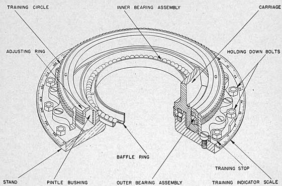
 To all holders of Ordnance Pamphlet 811 (1st. Rev.)