So far, generators and motors are the only instruments
described as using the principle of induction. COILS and
TRANSFORMERS, while much simpler in design and containing NO MOVING parts, also depend upon INDUCTION for
their operation.
Radios use hundreds of coils and transformers. Some
are large, over a foot long, and several inches in diameter,
while others are so small that a dozen could be placed
inside a cigarette pack.
Many coils and transformers have special names, such
as CHOKES, POWER TRANSFORMERS, INTERMEDIATE TRANSFORMERS, INPUT TRANSFORMERS, and many others. It
will not be unusual to hear all coils and transformers
called by a general name of INDUCTANCE or INDUCTOR.
SELF INDUCTION
One characteristic of induction is the ability of a COIL
to INDUCE a voltage in ITSELF-SELF INDUCTION.
87
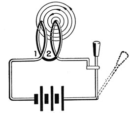
Look at figure 73. A coil of two turns is connected to
a battery through a switch. When the switch is closed,
the conductors will be surrounded by a magnetic field.
If only a SINGLE loop of wire were present, the magnetic fields would have little influence on the operation of
the circuit. But it follows naturally that the field surrounding loop 2 also cuts across loop 1.
Figure 73.-Self induction.
When the switch is FIRST closed, the fields surrounding
the loops are being CREATED. As long as the current is
INCREASING the field is EXPANDING-in other words MOVING.
Now here is the situation. You have a MOVING magnetic field and conductors-loops 1 and 2-so what will
take place?
Right! The field of loop 1 will induce a voltage in
loop 2, and the field of loop 2 will induce a voltage in
loop 1.
When the current through the coil becomes constant,
the fields become stationary and no INDUCTION takes
place. The field is SUSTAINED at a constant strength.
When the switch is opened, the SUSTAINING current
falls. The field BEGINS to collapse, moving in a direction
OPPOSITE to its motion when it was being created. In
88
collapsing, the field again induces a voltage in the turns
of the coil. Thus, whenever the magnetic field of a coil
is either EXPANDING or CONTRACTING, a VOLTAGE is INDUCED in its own TURNS.
COUNTER EMF
What happens to the voltage that is INDUCED in the
turns of the coil ? Does it AID, or OPPOSE the battery
voltage ?
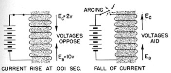
Look at drawing A of figure 74. The switch has just
been closed and the current is rising. The INDUCED
VOLTAGE is ALWAYS in OPPOSITION to the voltage that
CREATED IT. Thus, if the emf of the battery is 10 volts,
and the induced emf is 2 volts, the resulting emf tending
to cause the current to flow through the coil is-
10 - 2 = 8 volts.
After the current has reached a steady value, the
INDUCED VOLTAGE becomes zero, and the resulting emf
is-
10 - 0 = 10 volts.
As long as a steady current is maintained, no induced
COUNTER EMF is present, and the magnetic field remains
constant.
Figure 74.-Counter emf.
When the switch is suddenly opened, figure 74B, the
magnetic field will collapse and induce a voltage in a
DIRECTION OPPOSITE to the COUNTER emf, the SAME direction
699198°-46-7
89
as the APPLIED Voltage. Hence, on the collapse of a field, the INDUCED emf ADDS to the APPLIED emf.
If the switch is opened SUDDENLY, the induced emf from the collapsing field added to the battery voltage will cause a SPARK to jump between the terminals of the switch.
LENZ'S LAW
Here is something to remember. In any inductance,
the INDUCED voltage is always in OPPOSITION to the VOLTAGE THAT CREATED it. When the current caused by the applied emf is rising, the induced voltage tends to reduce the current; but when the current from the applied voltage is falling, the induced voltage tends to keep it going. This statement is known as LENZ'S LAW.
ON INDUCTANCE AND A. C.
In figures 73 and 74 you learned what happens when d.c. is applied to a coil. Now observe what takes place when a.c. is applied to a coil.
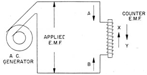
Figure 75.-Counter emf created by a.c.
In figure 75 an a.c. generator is delivering an emf to the inductance. During one half of the alternation, the current will be flowing in direction A, and during the other half-cycle, the current will flow in direction B. Since a.c. is never steady, a counter emf will be present at all times. The DIRECTION of this counter emf will always be opposed to the emf of the half-cycle that created it.
90
As an example, in figure 75, if the applied emf is in the direction indicated by arrow A, the counter emf will be in direction X, while on the next half alteration, the counter emf will be in direction Y.
INDUCTANCE OF A COIL
The magnitude of the counter emf depends upon two
factors-the construction of the coil, and the FREQUENCY
of the current.
The construction of the coil includes such factors as the NUMBER of TURNS per inch of the coil's length, the DIAMETER of the coil, the NUMBER of LAYERS of windings, and the KIND of CORE. All these factors are combined in a single unit and referred to as the INDUCTANCE of the coil.
The UNIT of inductance is the HENRY, and the SYMBOL
used to designate INDUCTANCE is the letter L.
The actual calculation of a coil's inductance is an involved and difficult process. But here's all you need to remember-the GREATER the number of turns, and the TIGHTER the winding, the HIGHER the INDUCTANCE. And a coil with an IRON CORE has a GREATER inductance than a coil with an air core.
Inductance is a PHYSICAL property of a coil, and it DOES NOT CHANGE with an increase or decrease of frequency. A certain type of coil, known as a "swing choke," is designed to have a HIGH INDUCTANCE with low current, and LOW INDUCTANCE with HIGH CURRENT. While the second statement seems to contradict the first, the cause of the CHANGEABLE INDUCTANCE is in the CORE and not in the COIL itself.
Coils used with audio frequencies may run higher than 30 Henries, while those used with high radio frequencies may be as small as a few MILLIHENRIES (thousandths of a Henry).
REACTANCE OF A COIL
The REACTANCE of a coil is the OPPOSITION to the flow
of current caused by the counter emf. The AMOUNT OF
91
REACTANCE depends upon the INDUCTANCE of the coil, and
the FREQUENCY of the a.c. applied.
Since a counter emf is induced each time the current
reverses its direction, the greater the number of reversals-the higher the frequency-the greater the counter emf will be.
The formula for finding the reactance of a coil is
simple-
XL = 2πfL
The symbol XL designates the reactance in OHMS; f is
the frequency of the a.c. in cycles per second; and L is
the inductance of the coil in HENRIES.
The factor 2 X π is derived from the ANGULAR rotation
of a cycle. Don't let it bother you. Just think of it as
equal to 2 X 3.14, or 6.28. So now the equation above
becomes-
XL = 6.28 fL
Suppose you have a coil of two Henries inductance,
carrying a 50-cycle current. What is the reactance?
Substitute in the formula, and you get-
XL = 6.28 X 50 x 2 XL = 628 ohms
But suppose the current is of an r.f. frequency of
2,000,000 cycles (2 mc). The reactance of the coil will
now be-
XL = 6.28 X 2,000,000 X 2 XL = 25,120,000 ohms
Remember, the HIGHER the FREQUENCY the HIGHER the
REACTANCE. This feature is used extensively in radio
work. You will hear a lot about it.
92
COILS USED IN RADIO CIRCUITS
The coils used in radio circuits are divided into two
classes-those designed to be used with AUDIO FREQUENCIES, and the others to be used with RADIO FREQUENCIES.
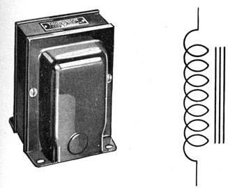
Audio frequency coils, usually called A.F. CHOKES, have
IRON CORES to increase their inductance. Figure 76
shows the schematic symbol and one example of an audio
Figure 76.-Audio frequency choke.
frequency choke. While this example is one of the most
common types, don't be surprised to find them of other
designs.
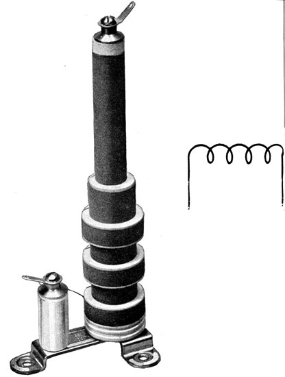
Radio frequency coils, R.F. CHOKES, usually don't have
iron cores. If they did, so much heat would be produced
in making and destroying the field in the core that the coil
would burn up.
R.F. coils have a greater variety of shapes and sizes
than a.f. types. Some of the windings are of fine wire;
others are made of large copper tubing with the individual
turns widely spaced. Figure 77 shows the schematic
symbol and one example of an r.f. choke.
93
Figure 77.-Radio frequency choke.
MUTUAL INDUCTANCE
When a coil is placed close enough to another coil so
that the magnetic field of the first induces a voltage in
the second. you have MUTUAL INDUCTION.
94
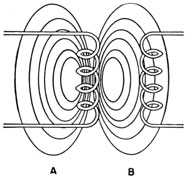
In figure 78, the magnetic field of coil A induces a
voltage in coil B. If the coils are far apart, coil A will
induce a small voltage in B. Moving the coils closer together INCREASES the emf induced in B. When the coils
are very close together, the magnetic field of the induced
current in B will induce an emf in A.
The relative position of the two coils is expressed as
the DEGREE of COUPLING. If the first coil is just able to
Figure 78.-Mutual induction.
induce an emf in the second, the coils are LOOSELY
coupled. When coil A induces a maximum voltage in B,
without B inducing a voltage in A, the coupling is CRITICAL. Any coupling greater than critical is CLOSE.
To keep the TYPES of INDUCTION straight in your mind,
remember that MUTUAL induction requires TWO coils,
while SELF induction needs but ONE.
THE TRANSFORMER
Mutual inductive devices are called TRANSFORMERS. In
figure 78, coil A is the PRIMARY winding and B the
SECONDARY. You can always tell which is the PRIMARY
because it is the coil WINDING that receives the APPLIED
voltage. The SECONDARY is the winding receiving the
INDUCED voltage.
Transformers are used with both a.f. and r.f. Audio
frequency transformers have iron cores, and the windings
95
are usually of heavier wire. Most radio frequency
transformers DO NOT have iron cores. The wires used for
the lower r.f. coils are fine and are wound on plastic tubes.
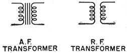
Figure 79.-Audio and radio frequency transformers.
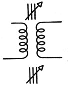
In figure 79, the schematic symbols for both a.f and r.f.
transformers are given. You will see each type with different numbers of loops, but the identifying feature is the
absence of the iron core with r.f. types.
Transformers operate on only a.c., because with d.c.
induction takes place only when the circuit furnishing
the applied emf is made or broken. Certain transformers are used with rapidly pulsating d.c., but these cases
are few. You may never see one used.
AUDIO FREQUENCY TRANSFORMERS
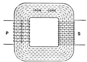
The core in audio frequency transformers is used to
increase its efficiency. The iron core forms a LOW
Figure 80.-A. F. transformer.
96
RELUCTANCE path for the flux to couple the primary and
secondary windings together.
In figure 80, the iron core forms a complete circle for
the flux to follow. In this way, any change in the
primary current will be quickly carried to the secondary.
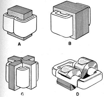
Not all transformers have cores and windings like the
one in figure 80. In figure 31, four types of cores and
windings are given. In drawing A, the core is circular,
Figure 81.-Transformer cores and windings.
but PART of the PRIMARY and PART of the SECONDARY is
wound on each side of the core. Both primary and secondary windings of drawing B are made on the CENTRAL
LEG of the core. Core C is just double that of B, and
core D is the one illustrated in figure 80.
97
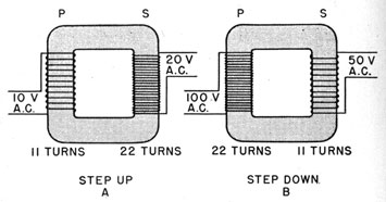
TRANSFORMERS CAN INCREASE OR DECREASE THE VOLTAGE
The transformer's ability either to increase or decrease the voltage is probably its most valuable feature.
Figure 82.-Step up and step down transformers.
If there are MORE windings on the SECONDARY than on the primary, figure 82, the transformer is a STEP UP. If the windings are reversed, with MORE on the PRIMARY, the transformer is a STEP DOWN.
The amount of step up or step down is directly proPortional to the TURNS RATIO between primary and secondary. Thus, in drawing 82A with 11 primary and 22 secondary turns, the voltage will be stepped up by a ratio of 1:2. Therefore, if 10 volts are applied to the primary, 20 volts will appear across the secondary.
With a step down transformer, if 22 turns are on the primary and 11 on the secondary, the step down is 2 to 1. Thus if 100 volts are applied to the primary, only 50 will appear across the secondary.
The step up and step down feature of transformers holds true for all ratios within reason. While, in theory, one turn on the primary and a thousand on the secondary should increase 10 volts to 10,000, ACTUALLY you would get much less. The difference between the THEORETICAL and ACTUAL performances is due to loss of efficiency with extreme ratios.
98
Efficient transformers with ratios as large as 20:1 are not uncommon, but when step up or step down ratios as large as 100 to 1 are desired, it is more efficient to use two 10 to 1 transformers.
Radio frequency also employs the step up and step down principle, but it is less commonly used because of the desire to obtain resonance in r.f. circuits. You will learn more about resonance in chapter 11.
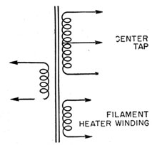
Radios use many transformers that are both step up and step down at the same time. Look at figure 83. The top secondary winding is step up and lower secondary winding step down. It is not unusual to have a single
Figure 83.-Step up, step down transformer.
transformer in a radio receiver's power supply deliver potentials like 600, 6.3, and 5 volts from three secondary windings.
YOU CAN'T TAKE OUT MORE THAN YOU PUT IN
It may seem at first that you are getting more out of a transformer than you put in, but if you look a little further you will see this is not true.
First, you know that it is impossible to take more power out of a device than you put in. That also holds true for transformers. The power you take out of the secondary
99
is EXACTLY equal to the power put -in the secondary.
Thus-
Primary power = Secondary power
or by using the power formula W = Ep X Ip = Es X Is
If the transformer is step up with a ratio of 1:2, and
50 volts with 10 amperes is applied to the primary, the
secondary will have an emf of 100 voltage but a current
of only 5 amperes because-
50 X 10 = 100 X 5
Thus if you STEP UP VOLTAGE, you STEP DOWN CURRENT.
RADIO FREQUENCY TRANSFORMERS
While most radio frequency transformers have primary
and secondary windings, they are called COILS. Don't
let that confuse you. If only one winding is present, it
usually will be called an r.f choke.
You were told that most of the r.f. transformers don't
have cores, but a few do have cores, made of IRON FILINGS
imbedded in a piece of PLASTIC. The symbol for transformers with iron cores is given in figure 84.
Figure 84.-Symbol for iron core r.f. transformers.
The windings of many r.f. transformers are of copper
tubing and are held in place by strips of some special
insulation material.
100
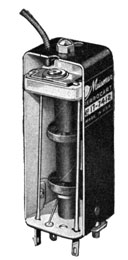
Figure 85.-Intermediate frequency transformer
Two of the many types of r.f. transformers are given
in figures 85 and 86. The one in 85 is small, only 2 or 3
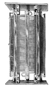
Figure 86.-Transformer used with transmitters.
101
inches long and about 1/2 inch in diameter. It is used in
the INTERMEDIATE stage of a SUPERHETERODYNE receiver.
You will hear more of these transformers later.
The transformer given in figure 86 is used with a low
frequency, high power transmitter. The coil is large,
over a foot long, and several inches in diameter.