The oldest and simplest known source of electricity, or
emf, is the static charge. It is possible to build high
static potentials of many thousands of volts. But these
charges cannot be used as a source of electric power, because they have no RESERVE of ENERGY to call upon to keep
the electrons flowing. With static charges, the potential
falls almost to zero once the spark has jumped-the-gap.
Static charges can be created continuously in a number
of different ways, but the RATE OF BUILDING is TOO SLOW
to make the charges of practical use as a source of emf.
For a long time, primary cells were the only source of
emf to power such devices as the telegraph and telephone.
Electric motors, heating coils, and 101 types of heavy
current consuming equipment, are common today. But
in the early days, batteries alone could not furnish the
65
required amount of current for such equipment. The
modern electrical machines had to wait until a cheaper,
more efficient, and larger source of emf was found.
The development of the principle of obtaining electricity from magnetism is relatively new-within the last
100 years-and is credited to a Danish scientist, Oersted.
Since the appearance of Oersted's first machine, rapid
progress has been made. GENERATORS have been enlarged
until now millions of kilowatts of power are delivered to
homes and industry daily.
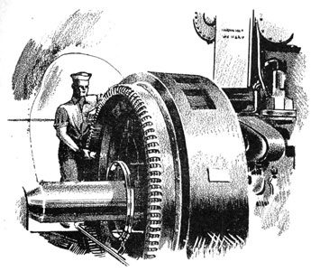
And you know the tremendous power of those big
ship's generators. Battleships and carriers have generators capable of supplying a city of moderate size with
enough electric power to run its factories, operate its
street cars, and to supply all the other electric power
requirements of the community.
The story of how a generator works starts with the
principle of electromagnetic induction.
INDUCTION
Here's the process of induction in a nutshell. WHENEVER A CONDUCTOR CUTS ACROSS THE FLUX OF A MAGNETIC
FIELD, AN EMF IS PRODUCED IN THE CONDUCTOR. If the two
ends of the conductor are connected to an outside circuit,
the induced emf causes current to flow in the circuit.
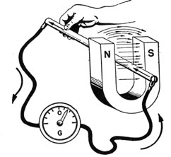
Figure 57.-An emf is produced when a conductor cuts a magnetic field.
66
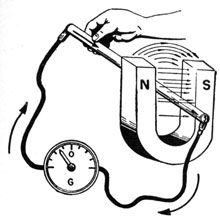
Figure 58.-Producing an emf by cutting a magnetic field.
Now, to see how induction works in a single set up,
study figures 57 and 58.
In figure 57, the GALVANOMETER, an instrument that
shows DIRECTION and AMOUNT OF CURRENT, is connected
to a CONDUCTOR. When the conductor is thrust DOWNWARD into the FIELD between the north and south poles
of a magnet, the meter needle is DEFLECTED, indicating a
FLOW OF CURRENT in the conductor.
Moving the conductor UPWARD (figure 58) causes the
needle to move in the OPPOSITE DIRECTION, indicating that
the direction of current flow has been REVERSED.
If you hold the conductor MOTIONLESS, no deflection
occurs.
A QUICK THRUST produces a LARGE DEFLECTION of the
needle. And a slow movement of the conductor causes a
small deflection.
Here is what you have observed-
Downward motion of the conductor causes current to
flow in one direction.
Upward motion causes current to flow in the OPPOSITE
direction.
The faster the movement, the greater the deflection.
No movement, no deflection.
67
In figures 57 and 58, the CONDUCTOR MOVED and the
FIELD STOOD STILL. But a VOLTAGE can also be induced by
MOVING the FIELD and holding the conductor STATIONARY.
Thus, INDUCTION will take place whenever you have a
MAGNETIC FIELD and a CONDUCTOR together, and a RELATIVE MOVEMENT occurs between the two.
PARTS OF ALTERNATING CURRENT GENERATOR
The Danish scientist, Oersted, discovered how to obtain
an emf by ROTATING a LOOP of wire in a MAGNETIC FIELD.
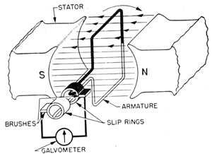
This device became known as the GENERATOR, a relatively simple machine with just four major parts-STATOR,
ARMATURE, SLIP RINGS, AND BRUSHES (figure 59).
Figure 59.-Parts of a generator.
The STATOR is a PERMANENT MAGNET placed in such a
position that the strongest field is between the two poles.
The ARMATURE is a loop of wire so placed in the magnetic field that during rotation the loop will cut across
the flux lines.
The SLIP RINGS are two complete copper rings. In figure 59, the BLACK ring is attached to the BLACK leg of the
loop, and the WHITE RING to the WHITE leg of the loop.
While not shown in figure 59, the LOOP and both SLIP
68
RINGS are mounted on a SHAFT. Mechanical power is applied to the shaft, causing the slip rings to ROTATE with
the loop.
The BRUSHES are pieces of carbon held stationary
against the slip rings by the generator framework.
The GALVANOMETER is not a part of the generator, but
is added to the drawing to indicate the direction of current flow.
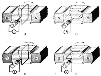
OPERATION OF A GENERATOR
Here is how the generator works. In figure 60, the
loop is rotating in a clockwise direction. At position A,
the TOP leg is moving toward the north pole, and the
LOWER leg toward the south pole. In position A, no flux
lines are being cut since both legs are moving PARALLEL
to the lines of flux. Since NO flux is cut, NO VOLTAGE is
INDUCED, and the GALVANOMETER needle STANDS at ZERO.
In position B, the loop has rotated 1/4 of a turn (90°).
The BLACK leg is moving DOWNWARD, and the WHITE LEG
UP. In this position, BOTH legs are cutting across a MAXIMUM
Figure 60.-Generation of an alternating emf.
69
NUMBER of LINES OF FLUX, and the emf, indicated
by the galvanometer, is MAXIMUM.
At position C the loop has rotated 1/2 of a turn. The
two legs are once more moving PARALLEL to the lines of
flux, and the galvanometer stands at zero.
In the last drawing, D, the black leg is moving upward,
and white leg downward. Both legs are again cutting a
maximum number of lines of force, but in the direction
OPPOSITE to that of position B. Since the legs are CUTTING the field in the OPPOSITE direction, the emf induced
causes the CURRENT to FLOW in the OPPOSITE DIRECTION.
The next 1/4 turn brings the loop back to position A,
and the cycle starts over again.
Now go back and see what happened during one rotation . The emf started at ZERO, increased to a MAXIMUM
value in ONE DIRECTION, fell back to ZERO, increased to
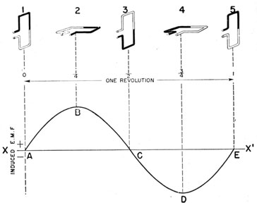
Figure 61.-An alternating emf.
MAXIMUM in the OPPOSITE DIRECTION, and then finally returned to zero.
Look at figure 61. The loop is shown in five positions.
Below the loop diagrams is a graph of the induced emf.
70
Line X-X' is the zero line. All the area above this line
is positive (+), and the area below is negative (-).
In position 1, the loop is cutting no lines of force, so
the induced emf is zero (point A on the graph).
One quarter turn later, the loop is in position 2. It is
cutting a maximum number of lines of force, so the emf
is maximum (point B).
At position 3, the loop has completed 1/2 of a turn, and
no lines of flux are being cut, so the emf is back to zero
at point C.
In position 4, the loop is cutting the field in the direction opposite to that of position 2. The voltage induced
in the coil is maximum, but in the opposite direction
(point D).
Position 5 is the same as 1, so the loop is ready to start
over again.
WHAT IS AN ALTERNATING EMF?
The emf produced by the generator in figure 60 is an
ALTERNATING emf. It starts at zero, rises to maximum in
one direction (+), falls back to zero, rises to maximum
in the opposite direction (-), and then comes back to
zero.
Notice in particular that the graph of an alternating
emf lies on BOTH sides of the ZERO line.
An alternating emf causes the current to flow first in
one direction and then the other. Hence the name, ALTERNATING CURRENT, or just plain A.C.
If the emf is ALL On ONE SIDE of the ZERO LINE, whether
all negative or all positive, it produces a DIRECT CURRENT.
Hence, the emf of an ALTERNATING CURRENT is on both
sides of the ZERO LINE (base line); but the emf of a DIRECT
CURRENT remains on ONE SIDE.
THE SINE WAVE
A sine wave is actually a MATHEMATICAL expression
showing the relationship between the ORDINATE and RADIUS values of a point as it rotates about the circumference
71
of a circle. But, don't let that floor you. You don't
have to understand the mathematics of the sine wave.
The important fact for you to know is that you get a sine
wave picture when you plot induced emf against armature rotation in a generator.
So you should be able to recognize the sine wave and
know something about its structure.
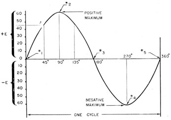
Figure 62.-A sine wave graph of an a.c. voltage.
In figure 62, point 1 is the same as point 1 in figure 61.
Ninety degrees of rotation later, the loop is in position 2,
and the voltage is maximum positive. The rising voltage
generated by the first quarter rotation of the loop is
included in the curve between points 1 and 2.
Directly below point 2, and on the zero line, the number
90° is written. The portion of the base line between 0°
and 90° includes angular ROTATION of the FIRST 1/4 rotation .
Now if you want to know the emf generated after 45°
of rotation, draw a VERTICAL line upward from the 45°
point on the base line (half way between 0° and 90°)
until it cuts the curve at point A. Draw a horizontal
line from point A over to the scale to the left, and you
72
will find it to be about 43 volts-that is, if 60 volts is the
maximum emf.
After the first 90°, the emf begins to fall. It continues
dropping until it is back to "zero," after 180° of rotation
(point 3). The loop has now completed 1/2 of a rotation
and is ready to start upward.
One quarter of a turn later, 270° after the start of the
rotation, the voltage is again maximum, but this time in
a NEGATIVE direction (point 4).
Beyond point 4, the voltage again falls to zero as the
loop returns to its starting point.
The next time around, the loop will generate the same
alternating emf, and so on for each rotation.
A complete rotation is called a CYCLE, and each rotation
thereafter is another cycle.
Thus, if 10 complete rotations are made in one second,
the FREQUENCY of rotation is 10 CYCLES PER SECOND
SIXTY ROTATIONS per second is a FREQUENCY of 60 cycles
per second-the frequency of the ALTERNATING CURRENT
used with commercial electricity power systems. You
have heard about that before.
MORE ABOUT FREQUENCIES AND CYCLES
You will hear the word FREQUENCY used thousands of
times in radio work. You will use it most commonly
when referring to the tuning of your receiver or transmitter.
As an example, you may say your transmitter is tuned
to a frequency of 4,200 kilocycles. What does it mean?
First of all, the word KILOCYCLE means 1,000 cycles per
second; therefore, 4,200 kilocycles is the same as
4,200,000 CYCLES per SECOND. Thus your transmitter is
generating an ALTERNATING CURRENT with a frequency
of 4,200,000 cycles per second.
In radio, you will use three expressions of frequency-
cycles
kilocycles
megacycles
699198°-46-6
73
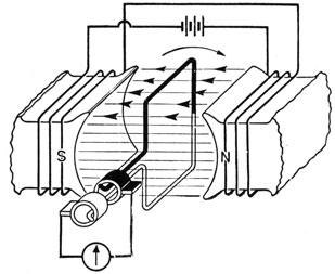
Figure 63.-A.C. generator with electromagnetic stator.
As you have been told, a KILOCYCLE is equal to 1,000
cycles. A MEGACYCLE is equal to 1,000,000 cycles.
Hence, a frequency of 31 megacycles is-
31,000 kilocycles, or 31,000,000 cycles
The megacycle is usually abbreviated Mc. or mc., the
kilocycle Kc. or kc., and the cycle (˜) just one cycle of
a sine wave.
Frequencies used in radio are divided into two basic
classes-
AUDIO FREQUENCIES, from about 20 to 20,000 CYCLES
per second, are those your ear can HEAR.
RADIO FREQUENCIES are all GREATER than 20,000
cycles and extend well above 30,000,000,000 cycles
(30,000 Mc.) .
It is the usual practice to refer to all frequencies
BELOW 20,000 cycles as A.F. or a.f., and those ABOVE
20,000 cycles as R.F. or r.f.
ELECTROMAGNETIC STATOR
In order to obtain a larger emf, a stronger ELECTROMAGNET is used for a stator instead of a permanent
74
magnet. The diagram in figure 64 shows a simple a.c.
generator with an electromagnetic stator. The source of
power to EXCITE the stator is shown as a battery.
ARMATURE
The armatures used with actual generators have many
turns of wire instead of a single loop. The wire is
wound on a core made of SHEETS of SOFT IRON, tightly
clamped together. The iron core is attached to shaft,
which is turned by a pulley and drive belt.
PART OF A DIRECT CURRENT GENERATOR
If you make a slight change in the slip rings of an a.c.
generator, you can obtain direct current instead of
alternating current.
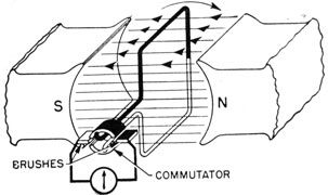
Figure 64.-Parts of a d.c. generator.
In figure 64, the two slip rings of figure 59 have been
Changed to a SINGLE, TWO-SEGMENT RING. The BLACK
leg of the loop is connected to the BLACK SEGMENT, and
the WHITE LEG to the WHITE segment. The two segments
are insulated from each other, so that no electrical contact is possible. The SPLIT RING is known as the COMMUTATOR.
The two BRUSHES are on opposite SIDES of the SPLIT
RING, mounted in such a manner that each brush is in
contact with only one segment at a time.
75
HOW A DIRECT CURRENT GENERATOR WORKS
The generation of the emf by the loop cutting across
the magnetic field is the same in a d.c. as it is in an a.c.
generator. The change to d.c. takes place at the COMMUTATOR.
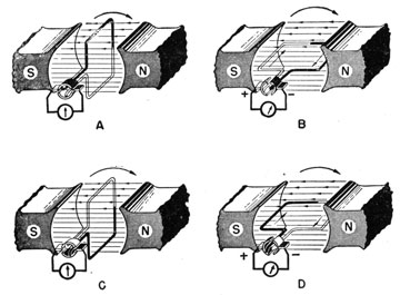
Figure 65.-Operation of a d.c. generator.
The loop in figure 65A is moving in a counterclockwise
direction, parallel to the flux. Hence, no emf is generated. Notice that the BLACK BRUSH is just coming in
contact with the BLACK segment, and the WHITE BRUSH
with the WHITE segment.
In position B, the flux is being cut at a maximum rate.
The BLACK BRUSH is contacting the BLACK SEGMENT and
the WHITE BRUSH the WHITE SEGMENT. And the galvanometer needle is deflected to the RIGHT.
At position C, the loop has completed 180° of rotation.
No flux is being cut, so the emf is zero. The important
thing to observe in position C is the action of the segments and brushes. The BLACK BRUSH is SLIPPING off
the black segment and ON TO the WHITE. At the same
76
instant, the WHITE BRUSH is leaving the WHITE segment,
and going on to the BLACK.
The SWITCHING of commutator segments also switches
legs of the loop. In this way the BLACK BRUSH is ALWAYS
in contact with the leg moving DOWNWARD, and the
WHITE brush in contact with the leg moving UPWARD.
While the current is actually reversed in the loop it is
ALWAYS FLOWING in the same direction through the galvanometer.
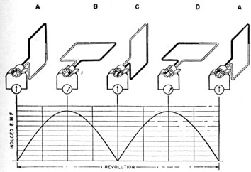
A graph for one cycle of a d.c. generator is given in
figure 66. The generation of the emf for positions A, B,
Figure 66.-Graph of a d.c. voltage.
and C is the same as for an a.c. generator. But at
position C, the brushes, in moving from one commutator
segment to the other, cause the current to flow in the
positive direction rather than becoming negative.
The d.c. furnished by a single loop armature is very
bumpy. It starts at zero, rises to maximum, and falls
back to zero TWICE for each rotation of the loop. To
produce a smoother d.c., more loops of wire are added to
the armature.
77
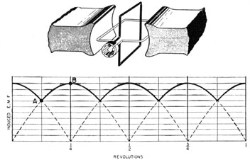
In figure 67, two coils are used instead of one. There
are now four segments but only two brushes in the commutator. With this arrangement, the voltage cannot
fall any lower than point A, so the bump in the voltage
Figure 67.-Voltage from a two-coil armature.
(ripple) is limited to the rise and fall between points
A and B. By adding still more armature coils, the
voltage ripple can be further reduced.