CHAPTER 20 THE ANTENNA IT'S MORE THAN A PIECE OF WIRE
You may think a radio transmitter's antenna is just a
length of wire running from the foremast to the mainmast, and that any dumb-bell can rig one. A receiver's
antenna may be that simple, but that is not quite true
for a transmitter antenna.
An ANTENNA IS a piece of wire. It is cut to the PROPER
LENGTH and CORRECTLY installed so that it will RADIATE
EFFICIENTLY the energy delivered to it from the transmitter. The word "EFFICIENTLY" is the word you want
to note well. ANY WIRE carrying an a.c. radiates electromagnetic energy-remember the HUM that your receiver
picked up from a 60-cycle power line? And the static
from a neon sign driven by an induction coil?
The power line and neon sign are not EFFICIENT RADIATORS because they were not designed to radiate energy.
The power line carries energy from the power plant to
your motor or light bulb, while a neon sign is built to
produce light.
699198°-46-14
201
But an ANTENNA is designed to RADIATE, in the form of
ELECTROMAGNETIC WAVES, the energy delivered to it by
the transmitter.
THE DIPOLE
The BASIC ANTENNA is a DIPOLE-a WIRE with a length
equal to HALF A WAVE LENGTH. If a station is operating
on a wave length of 100 meters, the dipole to be used at
that wave length will be-
100 / 2 = 50 meters, or about 164 feet.
A transmitter operating on a wave length of one meter
(300 mc.) will require a dipole 1/2 meter long-about 20
inches.
IMPEDANCE OF A DIPOLE
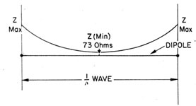
First of all, you must remember that an antenna carries a.c. Therefore the antenna will have inductive reactance as well as RESISTANCE. In a dipole, the impedance is MAXIMUM at BOTH ENDS, and MINIMUM at the
Figure 137.-Impedance of a dipole.
CENTER. In figure 137 the impedance is illustrated as
being greatest at each end, gradually diminishing until it
reaches minimum at the center.
202
Now this information, is just for your convenience-the impedance of a DIPOLE at its CENTER is approximately
73.2 ohms, REGARDLESS of what frequency you use.
CURRENT AND VOLTAGE IN A HALF-WAVE ANTENNA
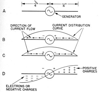
If a feeder line from the transmitter is connected to the
center of a DIPOLE, the antenna will operate as if you set
Figure 138.-Development of an antenna.
an a.c. generator between TWO QUARTER-WAVE antennas,
as in figure 138.
During one half of the alternation, the electrons will
flow from right to left, figure 138B. On the next half-alternation, the generator will make the electrons flow in
the opposite direction, figure 138C.
In an antenna, as in any other circuit, the flow of electrons is the GREATEST where the IMPEDANCE is LEAST.
203
Therefore, more electrons will be moving at the CENTER
of the dipole than at the ENDS.
What's the voltage along an antenna? Voltage is always GREATEST where the IMPEDANCE is the HIGHEST.
Thus you will find the HIGHEST VOLTAGE at the ENDS of
the dipole, figure 138D. During one half of an alternation, the left end of the dipole will be MAXIMUM NEGATIVE,
and the right end will be POSITIVE. On the next half
alternation, the POLARITY of voltages is reversed.
If the antenna extends EXACTLY one-quarter wave
length on each side of the generator, the REBOUNDING or
reflected ELECTRONS from the negative end of the dipole
will return at the proper instant to reinforce the movement of other electrons already moving in that direction.
But if the antenna is GREATER or LESS than one-quarter
wave length on each side of the generator, much of the
energy will be lost in the collision of electrons trying to
flow in TWO directions at the same time.
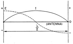
Figure 139.-Relationship of current and voltage in a dipole.
From the CURRENT-VOLTAGE diagrams of figure 139, you
can see the CHARACTERISTICS of an antenna. The current is MAXIMUM at the CENTER. The VOLTAGE is maximum POSITIVE at ONE END and MAXIMUM NEGATIVE at the
OTHER.
204
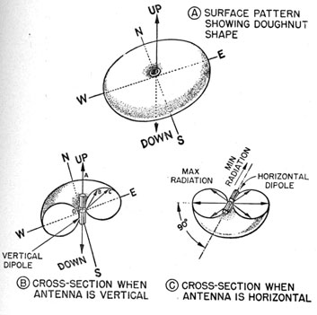
ELECTROMAGNETIC FIELD SURROUNDING A DIPOLE
A dipole suspended out in space away from the influence of the earth would be surrounded by an ELECTROMAGNETIC FIELD the shape of a DOUGHNUT, as shown in
figure 140. You see that no radiation takes place at the
ENDS of the dipole. If the antenna is mounted vertically,
Figure 140.-Electromagnetic field surrounding a dipole.
the field will have the shape of a doughnut lying on
the ground. All areas surrounding the dipole will receive a magnetic field of equal strength, as in figure 140B.
Set the dipole PARALLEL TO the surface of the earth-the
field is the shape of a doughnut standing on edge.
The GREATEST FIELD STRENGTH is along a vertical line
PERPENDICULAR to the dipole.
205
ELECTROSTATIC FIELD SURROUNDING A DIPOLE
High voltage at each end of the dipole produce an
ELECTROSTATIC FIELD which is at maximum strength at
the ends of the dipole. But if the antenna is shorter or
longer than a half-wave length, the electrostatic field
strength will be greatest at the point where the voltage
is maximum.
The electrostatic field is always present with an electromagnetic field. One cannot exist without the other.
In most cases, only the electromagnetic will be discussed,
but remember, the electrostatic is always there too.
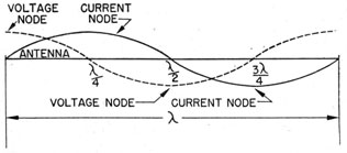
STANDING WAVES
The electrostatic and electromagnetic fields surrounding an antenna each form STANDING WAVES. The two
types of standing waves are as dissimilar as current and
voltage. The electrostatic field is 90° out of phase with
the electromagnetic field. The presence of an ELECTROMAGNETIC field can be shown by the glowing of a MAZDA
lamp-loop in the presence of the field, while a NEON lamp
will glow in the presence of an electrostatic field. The
points along an antenna where the magnetic fields are
MAXIMUM are called CURRENT LOOPS. The points where
the electrostatic fields are maximum are called VOLTAGE
LOOPS.
Figure 141.-Standing waves along full-wave antenna.
Figure 141 shows the location of the loop points along a
full-wave antenna. The CURRENT LOOPS appear every
206
half wavelength, and a VOLTAGE LOOP appears every other
half wavelength.
If you move a NEON bulb along an r.f. transmission line,
the bulb will glow each time a voltage loop is reached.
If the transmission line is several wavelengths long,
several voltage loops will be spotted.
You can determine the wavelength of your transmitter
approximately if you measure the distance between the
loop points, since each loop is exactly one-half wavelength
from the other.
ELECTRICAL LENGTHS AND ACTUAL LENGTHS OF
ANTENNAS
An ideal antenna, one completely free from the influence of the earth, would have an ACTUAL LENGTH exactly
equal to its ELECTRICAL LENGTH. For instance-an ideal
half-wave antenna for use with a 100-meter wavelength
would be 50 meters long.
Since no antenna is completely free from the influence
of the earth, the PHYSICAL length of an antenna is approximately 5 percent shorter than its ELECTRICAL length.
A half-wave antenna for a 100-meter station will be 50
meters minus 5 percent or 47½ meters long.
The physical length of a half-wave antenna for frequencies above 30 mc. can be calculated from the frequency
by using the following equation-
LENGTH (feet) = (492 x 0.95) / frequency, in megacycles
The number 492 is a factor for converting meters to
feet. The correction factor, 0.95, is 100 percent minus
the 5 percent loss due to the effect of the earth.
THE HERTZ ANTENNA
Any antenna that is one-half wavelength long is a
HERTZ ANTENNA, and may be mounted either vertically or
horizontally. The great length of HERTZ antennas makes
them difficult and costly to build to handle low frequencies.
Consider the problem of constructing a half-wave antenna
207
for a wavelength of 545 meters-550 kc. The antenna
would have to be about 851 feet long! You can imagine
the weight of a horizontal cable 850 feet long. And a
vertical half-wave antenna would be as tall as the RCA
building in New York's Radio City.
Because of the construction difficulties and costs, you
will find that half wave antennas are seldom used with
broadcasting transmitters operating at frequencies below
1,000 kc. But half-wave antennas are widely used with
high-frequency communication transmitters. A half-wave antenna for a 30 mc.-10 meters-transmitter will
be only a little over 16 feet long.
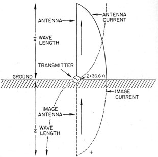
THE MARCONI ANTENNA
The MARCONI ANTENNA is also known as the QUARTER-WAVE ANTENNA, and the GROUNDED ANTENNA. Figure
142 illustrates the principle of a Marconi antenna
mounted ON the surface of the earth. The transmitter is
connected between the BOTTOM of the antenna and the
earth. Although the antenna is only ONE-QUARTER WAVELENGTH, the REFLECTION or IMAGE in the earth is EQUIVALENT to ANOTHER quarter-wave antenna. By this arrangement, HALF-WAVE operation can be obtained from an
antenna only a QUARTER wavelength long.
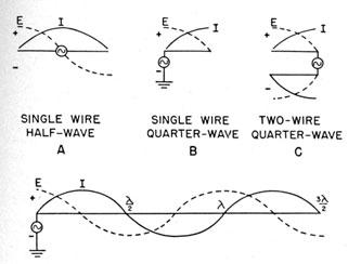
Figure 143.-Current and voltage relationships in antennas of various lengths.
The relationship of impedance, current, and voltage
in a quarter-wave ground antenna are similar to those
in a half-wave Hertz antenna. IMPEDANCE and VOLTAGE
are MAXIMUM at the TOP of the antenna and MINIMUM at
the BOTTOM. The flow of CURRENT IS GREATEST at the
BOTTOM and LEAST at the TOP.
The advantage of using a Marconi antenna can be seen
when you compare a length of 426 feet for a Marconi to
851 feet for a Hertz antenna at 550 kcs.
The quarter-wave antenna is used extensively with
portable transmitters. On an airplane, a quarter wave
209
mast or a trailing wire will be the ANTENNA, and the
FUSELAGE will produce the IMAGE. Similar installations
are made on ships. A quarter-wave mast or horizontal
wire will be the antenna, the hull and superstructure will
provide the image.
ANTENNAS OF OTHER LENGTHS
Occasionally you'll need an antenna of some other
length than one-quarter or one-half wavelength. You'll
see some of the usual lengths in figure 143.
Figures 143A and 143C are examples of CURRENT FED
antennas, while figures 143B and 143D are VOLTAGE-FED.
The expressions VOLTAGE-FED and CURRENT-FED refer to
the points along the antenna where the power is applied.
In the CURRENT-FED antenna of figure 143A, the power k
delivered to the antenna at the point of HIGHEST CURRENT.
The antenna of figure 143B is VOLTAGE-FED, the power being applied to the point of HIGHEST VOLTAGE.
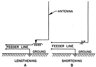
CORRECT THE ELECTRICAL LENGTH
After the antenna has been erected, you .may find that
its physical length is greater or less than its electrical
length. If a grounded antenna is less than one-quarter
wavelength, there will be a CAPACITIVE effect at the base,
and an INDUCTANCE must be added in series to increase
the ELECTRICAL LENGTH, as in figure 144A.
When the physical length of an antenna is GREATER
than its correct electrical length, the antenna will have
excess INDUCTANCE. In this case it will be necessary for
you to add a CONDENSER in series with the antenna to
SHORTEN its electrical length, as in figure 144B.
ANTENNA TUNING CIRCUITS
You will have to change the ELECTRICAL LENGTH of the
antenna each time you change the FREQUENCY of the
transmitter. Since you can't climb up the superstructure
and chop off a piece of the antenna each time you
210
increase the frequency, you will use a combination of
VARIABLE INDUCTANCES and CONDENSERS to adjust the
ELECTRICAL LENGTH. Condensers and inductances used
Figure 144.-Methods of correcting the electrical length.
for this purpose make up the ANTENNA LOADING or ANTENNA TUNING circuits.
TRANSMISSION LINES
The construction of a transmission line to carry LOW-FREQUENCY
a.c. is relatively simple, but the building of a
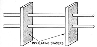
Figure 145-Open two-wire transmission line
211
line that will EFFICIENTLY transmit the energy of a HIGH-FREQUENCY radio transmitter to the antenna is something
else.
Transmission lines used with frequencies below 300 mc.
are of four general types-the OPEN TWO-WIRE system,
the COAXIAL CABLE or CONCENTRIC LINE, the TWISTED PAIR,
and the SHIELDED PAIR.
Figure 145 shows an open two-wire transmission line.
Wires are held rigidly in a parallel position by INSULATED
SPACERS. For 20 mc. and lower, a spacing of at least six
inches is desirable. For frequencies higher than 20 mc. a
spacing of four inches is best.
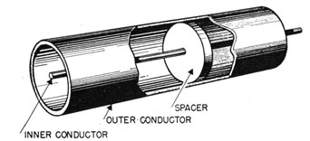
Figure 146 is a drawing of COAXIAL CABLE or a CONCENTRIC LINE.
It consists of a copper tube with a copper
wire extending down the length of the tube. The wire
is held centered in position in the tube by INSULATED
SPACERS
Higher operating efficiency is obtained by filling the
tube of the CONCENTRIC LINE with NITROGEN under several
pounds of pressure. But a pressurized line is often a
source of trouble. Vibrations caused by gunfire or rough
sea may cause leaks which allow the pressure to drop.
If this happens, the efficiency of the line will drop.
Figure 146.-Concentric line.
The concentric line has several advantages. The tube
is GROUNDED This allows you to install the line in any
convenient position Because the open two-wire system
212
lacks insulation, it must be carefully located. It is subject to stray capacitative and inductive coupling.
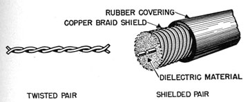
The TWISTED PAIR and the SHIELDED PAIR are not commonly used as transmission lines. Both types are shown
in figure 147. The twisted pair is the least efficient. The
Figure 147.-Twisted and shielded pair transmission lines.
shielded pair possesses an advantage in having a
GROUNDED OUTER SHIELD surrounding the two lines. This
shield prevents stray capacitative and inductive couplings.
RESONANT AND NON-RESONANT TRANSMISSION LINES
Transmission lines are either RESONANT or NON-RESONANT. A RESONANT line has characteristic STANDING
WAVES, while a NON-RESONANT line does not.
Remember the STANDING WAVE is the result of a certain
amount of energy being REFLECTED BACK along the transmission line. Imagine a transmission line so long that
NONE of the energy sent out by the transmitter ever
reaches the end of the line. Naturally, since none
reaches the end, none can be reflected back.
But no line is that long, so why not string up a line
of convenient length and connect a device to the far end
that will ABSORB ALL the energy traveling down the line?
Since all the energy is absorbed, none is left to be reflected
back. This gives you a NON-RESONANT line. To do this,
the IMPEDANCE of the ABSORBER matches the IMPEDANCE of
the ANTENNA. The absorber will collect all the energy
213
fed into the line and feed that energy into the antenna
to be radiated as a magnetic field.
A RESONANT LINE does NOT have its impedance matched
to the impedance of the antenna. This type of line is
actually an ANTENNA whose length is some multiple-1, 2, 3, etc.-of a QUARTER wavelength. You fasten one
end of the line to the antenna, the other end to the
transmitter.
RESONANT lines are usually OPEN TWO-WIRE SYSTEMS,
while the NON-RESONANT line may be TWO-WIRE, a CONCENTRIC, a SHIELDED, or TWISTED PAIR.
YOUR JOB AND ANTENNAS
You may never be called upon to rig an antenna, or
even change an installation you are using, but the knowledge of what an antenna is, and what it does will help you
in the tuning of your transmitters.
Remember the antenna's job is to radiate, in the form
of electromagnetic energy, as much as possible of the
energy delivered by the transmission lines from the transmitter. To do this, the antenna must be correctly built
and correctly installed. But more important as far as
you are concerned-the transmitter must be correctly
tuned and coupled to the antenna. That is your job.