CHAPTER 13 AMPLIFIER TUBES TRIODES-RAISE WHISPERS TO SHOUTS
Lee DeForest, in placing a GRID between the cathode
and the plate, completely changed the systems of communication. The addition of this THIRD ELEMENT made
it possible to start out with a feeble signal and build it up
to such strength that it could be heard by thousands.
This THREE-ELEMENT TUBE-the TRIODE-is not much
different from the diode in physical structure.
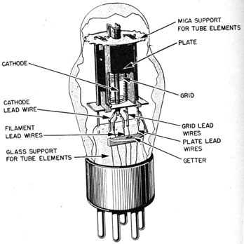
Figure 103 is a cutaway section of a triode. This tube
is an indirect-heater type. Notice that the cathode is a
small cylinder. The new element-the GRID-is the FINE
WIRE FENCE between the cathode and the plate.
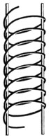
The grid is formed by winding wires on two metal supports. Notice in figure 104 that the wires and supports
look like the yard markers on a football field; hence the
name, GRID. Some vacuum tubes have more than one
grid.
127
Figure 103.-Cutaway section of triode.
Figure 104.-A grid.
128
THE GRID CONTROLS THE FLOW OF CURRENT
In the DIODE, the flow of electrons to the plate can be
controlled by changing either the temperature of the filament or the voltage on the plate. In a triode, the grid
is the most effective control on the flow of current from
the cathode to the plate.
Recall an old familiar principle that you learned in
d.c.-"Like charges repel each other?" In other words,
if two negative-charged objects are brought close together, they will push away from each other. That's
how the grid is able to control or regulate the flow of
electrons.
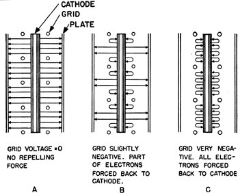
To see how this principle applies, study the diagrams
in figure 105. The three drawings are sections of a triode cut from top to bottom. The cathode is at the center.
The small round circles represent the END VIEWS of the
grid wires. The plate is indicated by the single line to
the outside.
Figure 105.-Effect of a negative grid on the flow of electrons to the plate.
129
In figure 105A, the grid is neither positive nor negative.
The electrons will go to the plate just as if the grid
weren't there. In other words, a triode with a neutral
grid behaves exactly like a diode.
The GRID of figure 105B has been made SLIGHTLY NEGATIVE. Since the electrons are also negative, PART OF THE
ELECTRONS that leave the cathode will be FORCED BACK
toward the cathode. Only a few will have enough energy
to "sneak by" the negative grid and get to the plate.
You know-likes repel.
In figure 105C, the grid has been made VERY NEGATIVE.
The FORCE OF REPULSION, offered by the grid, drives ALL
of the electrons back toward the cathode. Thus the flow
of current from the cathode to the plate is completely
stopped. The NEGATIVE VOLTAGE ON THE GRID that is
large enough to stop completely the flow of electrons
from cathode to the plate is known as the CUT-OFF voltage
of the tube.
THE GRID ACTS LIKE A VALVE
The grid in a triode may be compared to a valve in a
water pipe. If the valve is wide open, it will not exercise
any control on the flow. CLOSING the valve SLIGHTLY has
the same effect as making the grid SLIGHTLY NEGATIVE.
It will cause a SMALL REDUCTION in the flow. The MORE
the valve is CLOSED, or the MORE NEGATIVE you make the
grid, the GREATER will be the REDUCTION in the flow.
When the valve of a pipe is CLOSED COMPLETELY, flow of
water ceases. When the GRID is made EXTREMELY NEGATIVE, the flow of electrons to the plate is likewise stopped.
BIAS VOLTAGE
You have just seen that the number of electrons that
will be able to get to the plate depends upon the AMOUNT
OF NEGATIVE POTENTIAL ON THE GRID. The NEGATIVE
VOLTAGE that is placed on the grid to REDUCE THE FLOW
OF ELECTRONS is known as the BIAS VOLTAGE. It is important for you to understand that whenever the BIAS VOLTAGE
130
is NEGATIVE with respect to the cathode, the grid will
reduce the flow of current to the plate.
The reason for using a bias voltage on the grid is to
permit the grid to control the flow of current to the plate
on both positive and negative half-cycles of the signal.
If no bias were used, the grid could control the flow of
current on only the negative halves of the cycle.
COMBINED ABILITIES OF GRID AND PLATE VOLTAGES IN
CONTROLLING THE FLOW OF PLATE CURRENT
Since the plate voltage also influences the flow of plate
current, what will happen if the plate voltage is made
greater? Will the grid be able to exercise the SAME CONTROL, or will the conditions be changed?
First, stop and think what effect a larger plate voltage
alone will have on the movement of electrons to the plate.
When the plate is made more positive, it will offer a
GREATER FORCE OF ATTRACTION for the electrons. Thus,
if the grid is kept at a constant bias voltage, increasing
the positive potential of the plate will enable the plate to
PULL MORE electrons past the grid.
WHICH DOES THE BETTER JOB IN CONTROLLING THE
PLATE CURRENT?
Since both the grid and plate voltages are capable of
controlling the flow of current to the plate, it is interesting and important to compare the two to see which does
the better job.
Before you can make a comparison, it is necessary to
set up some standard to be used in judging the performance of the two contestants. This is not a new situation.
If you are to have a weight lifting contest, you will have
certain standard weights that ALL contestants must lift.
In a foot race, you will use a SET distance that all will
have to run.
It is much the same in the contest between the grid
and plate voltages. You don't have a distance that the
two must run, or a weight they can lift-instead, you use
a DEFINITE AMOUNT OF CURRENT THAT EACH MUST CONTROL
131
As an example of this, assume that the grid voltage and
the plate voltage each must INCREASE the flow of plate
current by 10 milliamperes.
The first thing that you will do is to KEEP THE BIAS
VOLTAGE CONSTANT. With the bias voltage constant,
INCREASE THE PLATE VOLTAGE until the plate current has
increased 10 milliamperes. After that trial run, you find
that it was necessary to use 40 ADDITIONAL PLATE VOLTS
to increase the plate current 10 milliamperes.
The score for the plate is now-
10 MILLIAMPERES--40 PLATE VOLTS
Return the plate voltage to the value it had before the
contest started. Now DECREASE THE BIAS VOLTAGE-make
it LESS negative-until the plate current has again increased 10 milliamperes. On this trial run, the GRID
increased the current 10 milliamperes with a voltage
change of only TWO VOLTS. The score board now reads-
Which one won the contest? The score is so lopsided
that you can't be mistaken. The GRID is by far the more
effective in controlling the plate current. What is the
ratio? That is simple; the GRID is-
40 / 2 = 20 times as effective as the plate in controlling the plate current.
The ratio of the effectiveness of the grid and plate
voltages in controlling the plate current is given a definite
name. It is called-
"Mu" or written in Greek symbol as μ
It is pronounced as-"Me-u" or "Mew."
THE Mu OF A TUBE
"IT TELLS HOW MUCH A TUBE IS ABLE TO AMPLIFY A SIGNAL"
Actually, the Mu of a tube is much more than a mere
interesting ratio. It tells you how much a vacuum tube
is able to AMPLIFY a weak signal that is placed on the
grid. Referring back to the contest just completed, two
volts of grid change produced the same result as 40 volts
132
of plate change, a ratio of 20 to 1. This may be turned
around and stated in another manner. With the vacuum
tube just discussed, if ONE VOLT OF A.C. is placed on the
grid of the tube, 20 VOLTS OF A.C. WILL APPEAR IN THE
PLATE CIRCUIT. And that is what is meant by AMPLIFICATION. The A.C. came in swinging feebly with one
volt, and left the plate circuit swinging 20 VOLTS. That
explains why the Mu of a tube is also known as-the
AMPLIFICATION FACTOR.
EFFECT OF TUBE CONSTRUCTION ON THE Mu OF THE TUBE
Now that you know that the grid voltage is able to
exercise such a large control over the flow of current
from the cathode to plate, you probably will think it to
be a case of the "tail wagging the dog." That is not
far from being the truth.
The reason why the grid is able to control the current
so effectively lies in the construction of the tube. The
GRID is placed MUCH CLOSER to the cathode than is the
plate. Therefore, any change in grid voltage will exercise as much influence on the movement of electrons as
a larger voltage change on the plate. In general, the
nearer the grid is to the cathode, the HIGHER the Mu of
the tube.
Typical triodes in common use have a wide range
of amplification factors. Some of the older styles, such
as the Type 27 tube, have a Mu of only 9, while the newer
Type 6SF5 tube possesses a Mu of 100. Don't think that
the tube with the highest amplification factor is the BEST
for all purposes. There are many other factors that will
influence the choice of the tube, but they are problems
that belong to the more advanced technicians and designers.
A.C. PLATE RESISTANCE
The one form of resistance is the A.C. PLATE RESISTANCE. More commonly called just PLATE RESISTANCE. It
takes into consideration the CHANGE in the PLATE VOLTAGE
that is produced by the CHANGE IN PLATE CURRENT.
133
To find the A.C. plate resistance of a tube, you will use
the SAME VALUES of Ep and Ip that you used earlier in
this chapter to find the Mu of the tube. These values
are-
ΔIp = 10 ma. or .01 ampere
ΔEp = 40 volts
The Δ means "change."
To find the Rp of a tube you change Ohm's Law for
resistance from-
R = E / I to ΔRp = ΔEp / ΔIp
and substitute the values-
Rp = 40 / .01 Rp = 4,000 ohms
TRANSCONDUCTANCE
So far, you have learned of two characteristics of a
vacuum tube, the amplification factor, Mu, and the internal plate resistance, Rp. A third factor-the TRANSCONDUCTANCE, obtained from the relationship of Mu and
Rp -expresses how well a vacuum tube is able to do its
work. It is a measure of the tube merit.
Don't let the word, transconductance, trouble you. It
has a very simple meaning-
TRANS-Means to transport, carry, from one plate to
the other.
CONDUCT-In electricity this means to carry ELECTRONS
through a conductor.
Now put these two, words together. In a vacuum tube,
what is carried or conducted from the cathode to the
plate? It is electrons! So transconductance merely
means-How WELL are the electrons CONDUCTED from
the cathode to the plate?
134
In any circuit, resistance expresses the opposition to
the flow of current. As you know, the unit used to express the AMOUNT of opposition is the OHM. Since CONDUCTANCE is just the OPPOSITE-tells how WELL a circuit
CONDUCTS CURRENT-the unit for expressing conductance
is the OHM written BACKWARDS, or the MHO.
The transconductance of a vacuum tube is a measure
of HOW WELL the grid voltage is able to control the flow
of current to the plate. It is expressed as the RATIO OF
THE Mu TO THE Rp of the TUBE. In an equation, it will
look like this-
TRANSCONDUCTANCE (Gm) = Mu / Rp (answer in MHOS-pronounced "Mose")
Here is an example of this-suppose that a triode has
a Mu of 40, and an Rp of 20,000 ohms. Substituting in
the equation and solving-
Gm = 40 / 20,000 Gm = 0.002 mho conductance
Because such a number as .002 mho is difficult to use,
and the tranconductance of all tubes is small, it is a common practice to multiply the MHO by 1,000,000 and call
the new number the MICROMHO. Thus 0.002 mho will
become-
0.002 X 1,000,000 = 2,000 MICROMHOS conductance.
For most vacuum tubes, the transconductance is in the
order of a few thousand micromhos. It is desired that
the vacuum tube have a LARGE Mu and a SMALL Rp
in order that it may have a high transconductance.
INTERELECTRODE CAPACITANCE
INTERELECTRODE CAPACITANCE is another high-sounding term, but it, too, has a simple meaning. You know
that a CONDENSER is formed whenever two pieces of metal
are brought near to each other. Within the triode, there
are THREE small condensers formed, one between the
135
CATHODE and GRID, another between the CATHODE and
PLATE, and the third between the GRID and PLATE.
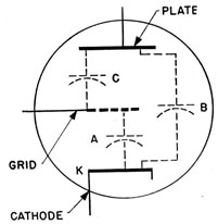
Figure 106 illustrates the interelectrode capacitance in
a triode. The capacitance that is formed between the
cathode and grid is the same as if a small condenser (A)
Figure 106.-Interelectrode capacitance in a triode.
were connected directly from the cathode to the grid.
The capacitance between cathode and plate is indicated
by condenser (B), and the grid-plate capacitance is indicated by condenser (C).
The capacitance between the plate and grid is the most
important, because it is the cause of much trouble. The
value of this capacity is small, usually less than 10 μμf
for a triode, but large enough in a r.f. circuit to feed a
considerable amount of energy from the plate circuit
back into the grid circuit (feed back). This causes
UNWANTED OSCILLATIONS.
These unwanted oscillations are so objectionable in
r.f. amplifiers that it is necessary to use special connections known as NEUTRALIZING circuits to keep the OSCILLATIONS down. Neutralizing circuits add to the bulk and
also reduce the overall efficiency of the set. You can see
that this is objectionable, especially in small receivers.
136
Another way of reducing the effect of this capacitance
is to keep the plate, grid, and cathode small in size. This
is done commonly with tubes designed to be used at very
high frequencies. The smallest of these tubes is called
an ACORN.
THE TRIODE-GOOD, BUT-
The triode is a good vacuum tube, but it has its limitations. The more important are-
FIRST-The amplification factor of a triode is small.
Therefore a triode requires a large DRIVING
POWER. In other words, a triode must be fed
a large signal before it can start the process
of amplification.
SECOND-The most objectionable feature of the triode
is its high INTERELECTRODE CAPACITANCE.
This is not objectionable at AUDIO frequencies.
But if the triode is used to amplify RADIO
FREQUENCY signals, you'll have to use NEUTRALIZING CIRCUITS to overcome the high interelectrode capacitance.
WHAT DOES INTERELECTRODE CAPACITANCE DO?
The grid and plate of a vacuum tube can be compared
to the plates of a condenser. To illustrate this, if the
plate is made LESS POSITIVE by an increased flow of electrons, the grid will become MORE POSITIVE. And, if the
plate is made MORE POSITIVE, the grid will become MORE
NEGATIVE. Therefore, just as in a condenser, ANY
CHANGE IN PLATE POTENTIAL WILL BE REFLECTED BACK
AND CAUSE A CHANGE IN THE GRID POTENTIAL.
In an r.f. circuit, this feed-back SETS UP EXTRA OSCILLATIONS AT ITS OWN FREQUENCY. If your radio receiver
or transmitter is a one-tube affair, these FEED-BACKS
won't be serious, because the extra oscillations are weak.
But a modern radio is not a one-tube job. All of the
extra oscillations produced by one tube are amplified by
69919V-46-10
137
all the following tubes. Therefore, you must kill off
those extra oscillations, or your transmitter will broadcast on SEVERAL frequencies at the same time. If feed-
back oscillations are present in a RECEIVER, it WHISTLES
FOR EVERY STATION, just like a train. You may have
heard receivers that feed-back, oscillate, AND whistle.