In the year 1883, Thomas A. Edison almost discovered
how the vacuum tube worked. In his experiments with
the incandescent light bulb, he was troubled by the repeated breaking of the fragile carbon filament. To give
the filament more strength, he placed supporting wires
alongside, but not touching the filament. A small piece
of insulation provided the bracing link.
One day, Edison attached the POSITIVE terminal of a
battery to the supporting wire and the negative terminal
to the filament circuit. To his surprise, he saw that a
CURRENT was flowing OUT of the bulb through the supporting wire. This wasn't according to the rules, since
there was no conductor connecting the filament and the
wire. Because he did not understand that current represents the flow of electrons, he wrote in his notebook-"When the positive terminal of a battery is connected to
the supporting wire, a current seems to flow. This is
an INTERESTING but WORTHLESS observation."
119
Interesting but worthless? In this case it paid dividends, but years later. In 1904, J. Ambrose Fleming,
an English scientist who understood the flow of electrons,
started to experiment with Edison's WORTHLESS observation.
He replaced the supporting wires with a large metal
plate. With this new tube he conducted many experiments, the results of which are summed up in the following statements-
FIRST: When a filament is heated red hot, electrons
will be given out by the metal and will form a cloud
about the filament.
SECOND: When a positive potential is placed upon the
plate, these electrons will flow from the filament to
the plate. By placing larger voltages on the plate,
the rate of flow can be increased up to a certain
point, beyond which no additional current can be
made to flow.
THIRD: If a negative potential is placed upon the plate,
no current will flow in either direction.
Because Fleming discovered that current could flow in
only one direction, the tube was known as "Fleming's
Valve." The English vacuum tube is still called a valve.
Back in the United States, Lee DeForest continued an
experiment in 1907 that had been suggested by Fleming.
DeForest placed a screen of fine wire between the filament and the plate. He found that when these wires
were made more negative than the filament, the flow of
electrons to the plate was reduced. If the screen was
made more and more negative, the flow was reduced still
further. If the screen was made negative enough, the
flow was stopped completely. The wires of this screen
were wound on a frame so that they resembled the yard
markers on a football field or gridiron. For that reason
the screen is called a GRID.
The use of the GRID in a vacuum tube to control the flow
of current from the filament to the plate is one of the
most important discoveries in electricity. The grid allowed the vacuum tube to grow up.
120
You'll study the simple vacuum tubes first and take up
the complex types later. Regardless of the number of
elements that are included within a single GLASS ENVELOPE, every vacuum tube goes back to the principle discovered in Edison's worthless observations-electrons
are given off by a hot metal filament.
DIODE VACUUM TUBE
The vacuum tube discovered by Fleming was a simple
TWO ELEMENT device-and after 40 years it's still a useful tube. Nearly every radio has at least one DIODE tube.
A high-powered transmitter may have several in places
where the current must flow in ONLY ONE DIRECTION.
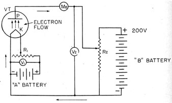
DIRECT-HEATER DIODE
The simple diode has only TWO ELEMENTS-the FILAMENT that is heated white hot and gives off electrons,
and the PLATE that attracts the electrons when it is positively charged. You call the portion of the tube that
gives off or EMITS electrons the CATHODE. And the part
responsible for heating the cathode is the FILAMENT.
In this simple diode tube, the CATHODE and FILAMENT
ARE THE SAME. This is a DIRECT-HEATER TYPE of cathode.
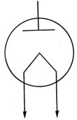
Figure 98.-Simple diode. Direct-heater type.
Figure 98 shows a simple diagram of a direct-heater
diode. The plate is a sleeve that surrounds the pyramid-
699198°-46-9
121
shaped filament. When the filament (cathode) becomes
red hot, electrons will be able to jump clear of the metal
and form a cloud around the cathode. This electron
cloud is the SPACE CHARGE.
The electrons in the space charge will move toward the
plate, if it is positively-charged, and more electrons will
come out of the cathode to replace those that move to
the plate.
INDIRECT-HEATER DIODE
In many circuits, especially those that use A.C. to heat
the filaments, the direct-heater cathode is a source of
much objectionable noise. To reduce this noise, the CATHODE and FILAMENT are made as TWO SEPARATE UNITS.
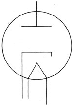
Figure 99.-Simple diode. Indirect-heater type.
Figure 99 shows a cut-away section diagram of an indirectly heated diode. The CATHODE is a METAL SLEEVE,
and the FILAMENT extends up through the center of the
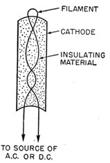
sleeve like the heating element in a soldering iron (figure 100).
The filament does not touch the sleeve, but is embedded
in a material that resembles plaster of paris. This filament may be heated with either a.c. or d.c. When the
cathode becomes red hot, it will give off electrons to form
122
the space charge. The filament is not connected to the
- cathode in any way, and the cathode alone gives off the
electrons. In an indirectly heated tube, the only function of the FILAMENT is to HEAT THE CATHODE.
RIVER OF ELECTRONS FROM CATHODE TO PLATE
You remember that when the PLATE is POSITIVE, electrons will flow from the space
charge around the cathode
Figure 100.-Indirectly heated cathode.
to the plate. This stream of electrons is called PLATE
CURRENT. In the standard abbreviations for radio terms,
the PLATE is indicated by P or p, and the CATHODE is indicated by the letter K or k. By making a combination
of I for CURRENT, and p for plate, you get the symbol
Ip for the PLATE CURRENT.
The amount of current that will flow to the plate depends largely upon the voltage on the plate. The higher
the plate voltage the larger the plate current. But the
increase of plate current with increase of plate voltage
does not go on forever. There is a point with every
diode where the plate current will no longer increase regardless of the amount of increase in plate voltage. This
is called the SATURATION POINT of the tube.
123
THE DIODE-A ONE WAY STREET
Remember the TURNSTILE at the circus or in the subway? You could push through it to go in. But when
you tried to turn around to come out the same way, the
turnstile locked, and kept you in. You could go in only
one direction.
And that's just how a DIODE works-it lets the electrons get INTO the PLATE from the CATHODE, but it refuses
to let them go back to the cathode.
The diode offers a low resistance from the cathode to
the plate, but an extremely high resistance from plate to
cathode. Actually the plate-to-cathode resistance is
equal to an OPEN circuit. Therefore, the diode is an
UNIDIRECTIONAL RESISTANCE. Since the diode is used
most frequently with a.c., the resistance is called UNIDIRECTIONAL IMPEDANCE.
THE DIODE AS A RECTIFIER
One of the most useful applications of the diode is to
CHANGE A.C. INTO D.C. Motor-generator units and other
mechanical devices have been developed for this job, but
for small amounts of power, none has the efficiency and
convenience of the diode.
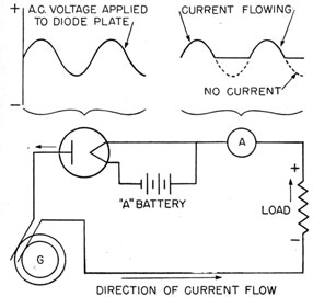
Figure 101.-The diode used as a rectifier.
124
The circuit for a diode rectifier is simple. In figure
101, a diode is inserted in the a.c. line. This arrangement will cause the diode to offer a low resistance in one
direction and a resistance equal to an open circuit in the
other.
On the half cycle when the plate is POSITIVE, the current will flow from the cathode to the plate. On the half
cycle when the plate is negative, NO CURRENT WILL FLOW
THROUGH THE TUBE. But on the next half cycle when the
plate is again positive, the tube will again conduct current.
Thus the current flow through the load will be a pattern of the POSITIVE HALF CYCLE that is applied to the
plate, but will cease to flow on the NEGATIVE HALF of the
cycle.
Figure 102 shows this relationship of the a.c. voltage
applied to the plate of the diode, and the current flowing
Figure 102.-Applied a.c. voltage and current flowing through a diode.
through the tube. Notice that you're using the POSITIVE
half cycles. You are actually wasting ALL THE NEGATIVE
125
HALF CYCLES; but you have succeeded in causing the current to flow in ONLY ONE DIRECTION through the load.
A diode that causes the current to flow in only one direction is called a RECTIFIER.