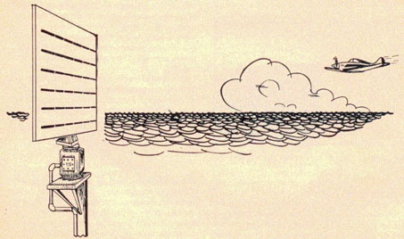
Various radars differ in physical appearance. Each has its special knobs,
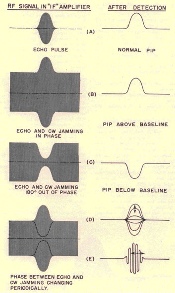
types of presentation,
and "gadgets," depending on the primary function of the individual set.
Regardless of this physical
variance, there is much that can be said, in a general sense, about good
operational techniques
for all radar sets. It is not intended, however, that the information in
this section be followed to
the letter under all conditions and in all tactical situations.
In order to gain the maximum tactical advantage from radar at all times,
the radar operational
techniques must change as the situation changes. Methods of operation
must be flexible. Commonsense, and a thorough knowledge of naval tactics must determine which of
these techniques
should be used in any given situation.
A brief outline of the various basic controls and indicators will form a
foundation for a more
detailed discussion of operational techniques.
1. Range scale. What scale should be used tinder what conditions? How
often should scales be
shifted?
2. Gain Control. This corresponds to the volume control of a broadcast
receiver. Should it be set
high, low, or medium?
3. Antenna rotation. Should the antenna be rotated continuously? How fast
should it turn?
Should it always search an area of 360 degrees? If stopped, for how long?
4. Range. How should ranges be read? Should the range step and
associated dials be used when
provided? Should estimated ranges be used with the assistance of
improvised scales?
5. Bearings. What are the different ways bearings can be read? Should the
bug be used, or
should a cursor be used instead?
6. Scope. If the radar set is equipped with two or more types of
cathode-ray indicators, which
should be used, and under what conditions is one preferable to another?
The answers to these questions, for different types of radar sets
operating in various tactical
situations, will provide you with the foundation of operational
techniques. From this foundation,
each special circumstance will require variations which can only be
determined by radar operating experience and common sense.
There are three basic types of radar:
1. Surface search
2. Air search
3. Fire control
In this section, the operation of the first two types will be discussed
in general terms. However,
since fire-control radars have such widely varying characteristics,
recommended operational
techniques will be particularized for each type, and will appear only in
Part 4.
Each type of radar has been designed for one specific purpose, and there
is nothing that you, as
an operator, can do to modify these purposes. An air-search radar is a
poor surface-search
radar, and vice versa. Each of these types may serve in an emergency as a
fire-control radar,
but they cannot he expected to furnish ranges, bearings, and position
angles with the same
degree of accuracy as a fire-control radar specifically designed for that
purpose. In case of
failure of either the air- or surface-search radars, the fire-control
gear may act as a search
set.
SURFACE-SEARCH RADAR
The words surface search are misleading, since search is only one of many
functions that has
been delegated to this general type of radar. The six major functions are
listed below, together
with suggestions for optimum radar efficiency under each condition.
Long-range search for large targets.
It is essential that large surface targets be detected at the maximum
possible range of the radar,
so that effective attack or evasive tactics can be employed. The range
scale used should be longer
than the expected maximum range on ships. The gain control should be set
for maximum
readability of an echo at 30,000 to 60,000 yards. This setting must be
previously established
for each particular radar set. The antenna should be rotated at the
slowest available speed; an
occasional sweep should be made using the manual control, if one is
provided. The "A" scope (if
the radar is so equipped) will usually show the initial contact before it
appears on the PPI.
3-3
RADAR OPERATOR'S MANUAL
If a contact is established, stop the antenna (when means are provided
for stopping it on
contact) only long enough to obtain an initial bearing and the "A" scope
range. Attempt to
classify the contact specifically by utilizing previous knowledge of the
capabilities of your
particular radar. Data concerning previously observed maximum ranges on
different types of
ships, size of pip, and composition of pips will be useful in making this
decision. Two courses of
action are now open to you. You may follow the procedure outlined for
auxiliary fire-control, or
you may resume normal search. Your decision will naturally be based on
the tactical situation.
Assume for this discussion that you are not interested in firing on the
new contact. However,
you might desire to keep a rough track thereof in order to maneuver
around it. Your procedure,
then, would be to continue a long-range search, reading bearings and
ranges of the contact "on
the fly," without stopping the antenna. With practice, sufficiently
accurate data may thus be
obtained to maintain a reasonably exact track. The important
consideration of the on-the-fly
operating technique is that you are continuing to search for other
contacts (which the Captain
may later decide to attack) without sacrificing the search efficiency of
the radar by stopping its
antenna on a contact that admittedly is not of primary interest.
Ranges read on-the-fly will be more nearly accurate
and easier to obtain if the "A" range scope is equipped with a
scotch-tape range scale, and if the
PPI is marked with thinly inked range circles. Bearings can be estimated
directly from the PPI.
Short-range search for small targets.
This might be called the submarine or PT boat search, and should be
conducted primarily when
cruising independently. When cruising in company, the OTC will normally
assign the search
function of each radar in the force. The range scale used for small target
search should usually
be the shortest available scale, although on some sets it may be found
that the mid-range scale
can be used to better advantage. The receiver gain should be varied
during the entire search , its
setting depending on the amount of sea return present and other tactical
considerations. Look for
periscopes close aboard, increase the gain a little, and search near the
outer limits of the sea-return area for surfaced submarines and small patrol craft. Remember that
sea return is
basically the same as an echo from a target, and that it must be present
if a small target echo is to be detected.
Operating experience will determine the correct gain setting for
different amounts of sea
return. Antenna rotation should be as slow as possible; again, make
occasional manual
searches. New targets should appear on either the "A" scope or the PPI
almost
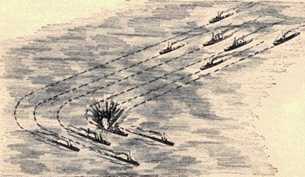
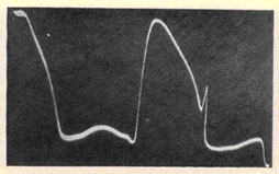
Figure 3-1. Avoid this by using radar when changing course or leaving a formation.
3-4
OPERATION OF MAJOR TYPES OF RADAR
simultaneously, provided the gain is set high enough for PPI operation.
These indicators should
be alternately observed for equal periods of time to reduce eye strain
and monotony. If a contact
is made, follow the procedures listed for long-range search. If an attack
is to be made on the
targets, coach the fire-control radar on to the contact and resume the
search immediately. There
is no need to attempt to duplicate the function of the fire-control radar
with the search radar,
unless the search radar is required to solve a torpedo problem while the
main battery fire-control radar is busy.
Station keeping.
There are some situations that will demand the exclusive use of a search
radar set for station
keeping. It must be understood that when this radar is used for station
keeping, it is not
performing its intended purpose as a search radar.
The normal requirements of station keeping are such that the antenna
should be rotated
continuously, using the short range scale on the indicator. Bearings and
ranges on the guide, or
on other suitable ships in the formation, may be estimated from the PPI
scope. It has been found
useful, when proper conditions prevail, to maintain a plot directly on
the face of a remote PPI
scope with a chinagraph pencil, or to put a spot on the master PPI
representing the place on the
scope where the guide should appear when you are on station. Any
indication of incorrect station
will become immediately evident in this system. Search should not be
forgotten when keeping
station, and a regular plan of shifting range scales and receiver gain
should be adopted. The gain
should be turned down only while obtaining necessary station keeping
information.
Admittedly, there are situations that demand extremely accurate station
keeping. When such is
the case, auxiliary fire-control procedure should be followed, utilizing
the most accurate
ranges and bearings available from the radar. Search must necessarily be
forgotten, or
minimized, during intricate maneuvers.
Navigation.
One of the most useful functions of a surface-search radar is its
contribution to navigation.
However, the limitations involved when radar is put to such use must be
thoroughly understood.
Unless you know the contour and composition of the land that is
reflecting the radar energy you
are never safe in reporting a range to the "nearest point of land." For
instance, if you are
ranging on a sharp cliff that rises
directly upward from the water's edge, you are safe in assuming that the
range to the nearest
land is positively indicated by the range obtained from the radar screen.
If, however, the
terrain rises gradually from a waters edge to a mountain or range some
distance inland, the
possibility exists that the pip on your radar screen has been produced by
reflection from the
mountain range, and not from the beach. It is almost impossible to
determine the exact point of
reflection from a sloping surface, and an error of only a few hundred
yards might prove
disastrous in close navigational work. Always keep a contour map of
nearby land available for
reference when navigational information is required. After careful
practice in "radar map"
comparison with contour maps of familiar land, you may become proficient
in estimating
reflecting surfaces on unfamiliar terrain. This discussion applies, of
course, to piloting, since
radar "cutons" will usually differ from visual tangents, depending again
on the contour of the
land.
The beam width of the antenna must also be considered when an attempt is
made to obtain a radar
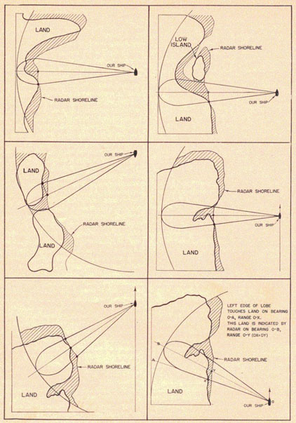
picture of a shore line. A few illustrations will show why this is so.
The first series of illustrations in figure 3-2, show how the radar shore
line changes as the
ship moves from one position to another. Notice that the harbor has been
completely obscured
by the radar shore line in all instances, and that a ship that might be
situated anywhere inside
the shaded areas would not appear on account of this beam-width
distortion. The explanatory
remarks in the first drawing are applicable to all of the subsequent
illustrations.
All of the examples have been based upon the assumption that equal
reflection is obtained from
all points along the shore line. While this is rarely the actual case, it
is a necessary assumption
for a theoretical situation. The radar shore line will differ from the
actual shore line by an
amount depending upon the beam width of the antenna, the contour and
composition of the land in
the immediate vicinity of the shore line, the bearing of the ship from
the shore at any given
time, and the amount of receiver gain used.
It is impossible to describe all situations that might he encountered in
ranging upon a shore line
with radar. Each problem has its own special features, and must be
treated individually by the
ship involved.
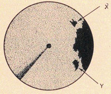
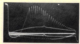
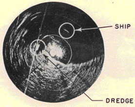
More accurate fixes can be obtained if echoes from smaller land masses
are used. On the PPI
shown in figure 3-3, points X and Y would provide the best navigational
fix.
3-5
RADAR OPERATOR'S MANUAL
Figure 3-2.
3-6
OPERATION OF MAJOR TYPES OF RADAR
It is often helpful to plot the range and hearing backward from your
estimated, or DR position,
and analyze the chart to determine if there is a possible reflecting
surface. Good and had ranges
may he identified in this manner. It should he remembered,
Figure 3-3. Small land masses provide accurate navigational fixes.
however, that the chart itself may he in error, so its known accuracy
must be considered in this
procedure. A collection of sketches of the composition of pips may be
useful when you return to
a particular location.
Figure 3-4. Prominent landmark pips help in locating ship's position.
Auxiliary fire control.
You are, by definition, using your surface-search radar as a
lire-control radar as soon as you
start to track a contact. This is often a desirable procedure in spite of
the fact that the search
efficiency is decreased during such operations. If your ship has no
fire-control
radar, or if such equipment has failed, you may have to depend
completely on surface-search radar for the control of gunfire.
The radar operator must furnish more accurate ranges and bearings than
those provided by
obtaining them "on the fly." There are two methods of developing a plot
for fire-control work.
These will be explained in detail in RADFIVE. Regardless of which method
has been selected, you
must stop the antenna to obtain accurate ranges from the "A" scope and
bearings from the
bearing indicator. If no "A" scope is available, the most accurate method
of obtaining this data
must be selected, depending upon the particular radars installed.
For radar spotting, the antenna must be fixed on the target while the
shells are in flight so that
splashes may he noted on the radar indicator. The torpedo-control work is
usually delegated to
surface-search radars and CIC, since the fire-control radar is busy
furnishing necessary
information for the solution of the gunfire problem. In spite of the high
degree of accuracy
necessary to the satisfactory solution of fire-control and
torpedo-control problems, the best
procedure is to make one or two complete antenna rotations every minute
or so to make sure
that bigger game is not approaching from a different bearing.
Composition.
Continuous practice is needed by all radar personnel before they become
proficient in analyzing
the pip on a radar screen. Every opportunity should be utilized when in
company with friendly
ships to make notes (on effects of position angle, size and type of
targets, ranges, and relative
bearings) on the composition of an echo.
Familiar double-peaked echoes are often noted from large ships, such as
battleships and
carriers, at medium or close ranges. Fluctuations of the pip are
different when the reflecting
object is a rolling destroyer or a more stable cargo vessel. These are
among the "tricks if the
trade" that must be mastered by an operator before he can he considered
above average.
AIR-SEARCH RADAR
The continually changing tactics of the enemy relating to air attacks
makes it difficult to outline
the best operating techniques for this type of radar. Although the basic
tactical situations will
be discussed in this section, it would he well to remember that there are
no set operating
conditions that will hold true for all conditions of radar protection and
offensive action.
3-7
RADAR OPERATOR'S MANUAL
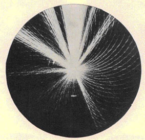
Long-range, early warning air search.
The problem involved in this type of search is obvious. We want to make
initial radar contact
with the enemy attack groups at the maximum radar range. Patrol planes
and snoopers most be
intercepted before they can radio contact reports about our task force.
The range scale should he set to provide the longest available range in
accordance with the
observed maximum ranges of the particular radar, The PPI and the "A"
scopes should be watched
alternately, with the antenna rotating slowly. Receiver gain should he
set for maximum
readability of the indicator under observation. This means that the gain
control will be at a
different position for "A" and PPI operation.
Upon radar contact, the antenna should be stopped, and the echo
scrutinized to determine the
composition of the pip. The target should be challenged with the BL, and
the "A" scope should
show the IFF response if the target is friendly.
The slow antenna rotation should be resumed immediately, and the
all-around search continued
to detect other possible targets. The procedure to follow at this time
will vary, depending on
many factors too numerous to present in this book. The type of force, the
availability of
fighters, and the discovery of other bogies will influence the decision
of the task force
commander, but this much can he said for the general case: the discovery
of a bogie demands an
even more
thorough search of the 360 degrees area around the force. Keep the antenna rotating slowly.
Bearings should be obtained from the bearing cursor on the PPI, and
ranges should be estimated
directly from the PPI without using the range mark. This will be
facilitated by inking range
circles at five-mile intervals on the glass surface of the PPI tube,
eliminating the use of the
unsatisfactory range scale provided with these units. When the PPI is not
available, ranges and
bearings must be read "on the fly" with the aid of a scotch-tape range
scale on the "A" scope.
Short-range search and multiple target tracking.
This search procedure could be followed when a torpedo plane attack is
imminent or probable,
and when raids are approaching from different bearings. Continuous
antenna rotation is a
necessity. The range scale should be set at its medium position, and the
gain adjusted for
maximum readability of the PPI. Ranges and bearings must be obtained in
the same manner as
that discussed for long-range search (from the PPI).
The speed of antenna rotation should be increased as the attack closes on
the force, and you must
be prepared to shift to the short-range scale as soon as the targets have
reached the outer range
limits of this scale. You must also be prepared to change to fire-control
liaison operation since
it is closely allied to short-range search operation.
Figure 3-5. Long-range, early warning, air-search radar.
3-8
OPERATION OF MAJOR TYPES OF RADAR
It is particularly important to maintain a plot of all friendly planes in
the air when contact
with the enemy is possible. Unless this is done, a "snooper" or low-flying
attack plane may
appear on the screen of the radar unknown to the operator. This practice
may require that the
antenna be periodically stopped to check the IFF return, but once a track
has been started on
any particular plane, the identification problem should be simplified, and
bogies detected
immediately.
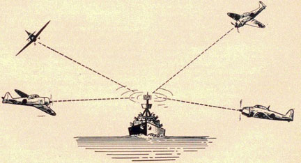
Fighter director tracking.
For night interceptions this type of radar operation should be carried on
during night fighter
work so that the fighter director officer can effectively make a PPI
interception. The 360 degrees
search is abandoned, and the antenna is directed over only the area in the
vicinity of the
attempted interception. This method, however, concentrates all your efforts
on a small area, and
should be utilized only if there is sufficient air-search coverage from
other radars in the force.
If the operator-plotter team is unable to provide an up-to-the-minute radar
picture of
daylight interception, fighter director tracking must be employed.
Multiple-target tracking is
preferable to this method, however, since all areas are covered by the
radar.
Over land tracking and over land search.
Tracking targets over land is not as difficult as it may seem at first,
although it is an art which
requires considerable practice. Actually it is a special type of
fighter director tricking requiring its own special technique.
Whenever planes fly over land masses, their contacts can not be seen on the
PPI. Use the "A"
scope and the shortest range scale on which the plane can be seen (if you
intend to track it).
With the antenna in manual rotation, train slowly through the land mass,
watching for a
bouncing pip among the steady ones. This will indicate the presence of a
plane over land, and you
may then read its range almost as accurately as if land were not there. To
find its bearing,
adjust the antenna carefully for maximum activity of the bouncing pip.
You should practice this technique on friendly planes when in port. IFF
affords an excellent
method of checking from time to time to be sure that you are on the plane.
Fire-control liaison.
When attacking groups of planes have closed within 20 miles of the force,
it is essential that
close cooperation be maintained between the air-search radar and the
fire-control radars. The
guns must often be "talked on" directly from the air-search radar, or by
electrical target
designation systems connected to that radar.
Depending on the particular installation, the radar may be set to furnish
either true or relative
bearings. It is preferable to utilize true bearings, provided suitable
conversions have been
incorporated in the
Figure 3-6. Speedy antenna rotation for short-range target tracking.
3-9
RADAR OPERATOR'S MANUAL
fire-control equipment. If not, relative bearings should he furnished.
The antenna should be rotated as fast as possible, and the range scales
used should be the
shortest available on the radar. While this measurably decreases the air-search efficiency of the ship, primary consideration
should be given to gunnery
when planes have closed to attacking ranges.
Side lobes are especially troublesome in this type of operation, and the
operator must be quick
to distinguish the extraneous echoes involved. It will help to reduce the
gain as far as
practicable, in order to minimize these echoes. They may often be
distinguished by comparing
their width (in degrees)
with the echo received due to the main-lobe radiation.
Composition.
The "A" scope is of the greatest value when the composition of a contact
is to be obtained.
Constant drill by operating crews in estimating the composition of
friendly planes is of
inestimable value as a means of obtaining reliable data to be used on
enemy raids.
Composition of raids should be checked at regular intervals, about every
20 miles of target
travel, to make sure that any splitting of attack groups may be noted:
the estimated size of the
raid should be rechecked.
PIPOLOGY
INTRODUCTION
Pipology involves the study and interpretation of all types of contacts
seen on radar indicators.
Composition is a closely related word, but not so all-inclusive, and
answers the questions: what
type? how many? friend or foe? Determination of composition is an art,
and is perhaps the
most enjoyable phase of radar operation. Given enough time, almost anyone
can get the bearing
and range of the target, but it takes skill, imagination, and above all,
experience to determine
composition. With continued experience and increased skill your
predictions should be about
80% correct. Trying to identify every echo that appears will give you the
practice you need, and
whenever possible, get someone to find out what the target is, or was,
and thus check the
accuracy of your estimate.
Ability to interpret pips comes both from knowledge gained through study
and from endless
hours of practice on the radar. It is important not only to recognize the
target, but also to
recognize it in the shortest possible time. Some of the advantages of
speed are:
1. It aids the plotters in assembling information.
2. It aids the ship's officers in making quick evaluations and decisions.
3. It gives the gun-director crew and computer operators much needed time
in laying guns on
the target.
4. It adds to the over-all efficiency of the radar watch.
Pips are of various types. Each type lends itself to interpretation. In
general there are four
characteristics of pips which will give you information useful in
interpretation.
1. Size of pip.
2. Shape of pip.
3. Bobbing or fluctuating in height.
4. Movement in range or bearing.
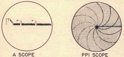
The "A" scope is most satisfactory for observing size and fluctuation of
pips, an expanded or
short range "A" scope for observing shape , while movement is best seen on
the PPI. The
following section takes up these pip characteristics in some detail to
aid you in interpreting the
things you are likely to see on radar scopes.
COMPOSITION
Friend or foe.
The first thing to determine obviously is the friend or foe status of the
contact. This can be done
only by using your IFF interrogrator, or by securing the information from
another ship in
your force which has already established this status. The method of
handling such a situation is a
matter of doctrine. You will be informed as to whether or not you are to
make the identification,
generally you do.
Having established the friend or foe status of the contact, the next step
is to notice the rapidity
and the extent of the echo's fluctuation. Consider the height of the
echo, remembering the effect
of range and fades; then note the depth or thickness of the echo. If the
echo is saturated, reduce
the gain. Look at the top and sides of the echo for any indication of two
bumps or many little
humps. What is the speed at which the echo is moving? Look at everything
and draw on your
entire background of knowledge and experience to interpret what you see.
3-10
PIPOLOGY
Estimating the size of ship targets.
First of all, upon what does the size of the pip (strength of received
echo) depend? The answer
is, unfortunately, quite a number of things, the most important of which
are:
1. Range of the target.
2. Size of the target.
3. Height of your antenna (especially when surface targets are concerned).
4. Height of the target.
5. Whether the target is bow or broadside (target angle).
6. Atmospheric conditions.
7. Material composing the target.
8. Correctness of tuning.
9. Materiel condition of the radar set.
Due to the many variables involved, it is not possible to determine the
exact size of the target in
every case, but you can always make a reasonably
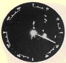
Figure 3-7. Two medium, three small targets.
accurate estimate. This much you do know: if you have a large and a small
target at
approximately the same range, the larger target will produce the large
pip (stronger echo),
other variables being equal. So, if you detect any enemy task force
approaching, the picture on
your PPI might appear as shown in figure 3-7. Thus, the only positive
thing that size of pip
will tell you is relative size of various targets at approximately the
same range.
The best way of determining the approximate size of a target is to
observe the range at which it
was first detected. This method is especially good with micro-wave
surface-search radars such
as the SG, SF, SL, SO, etc. Radio waves from these radars travel in
practically a straight line. At
any given range it takes a certain size object to give back an echo that
is just visible on the
screen or scope with your radar tuned up as well as possible. Therefore,
various types of
targets or types of ships first become visible on the scope at some
definite range. The echoes
come from the ship's mast and upper superstructure first. The
superstructure offers
approximately the same size target regardless of the direction from which
it is seen.
Each radar will have its own characteristic ranges for detecting the
various types of targets,
depending on how high the antenna is mounted, the power, and the
sensitivity of the particular
gear.
An estimate of the approximate size of targets at less than the maximum
range can be made by
considering the strength of the echo, the range, and the target angle. To
facilitate this process a
log should he kept for recording these data. The data can then be
tabulated for quick reference,
showing echo strength in E units, range, target angle, and type of -hip,
as well as any special
features of the pip that might be noticed.
The E system of designating echo strength is based on the ratio of the
echo height to the grass
height. This ratio is not affected by the setting of the gain
control. See figure 1-17 in Part 1, General Radar Principles.
Target angle is an important consideration except at extreme maximum
range. It is the angle
measured from the bow of the target ship, clockwise (to the right) to a
line drawn between your
ship and the target ship. In other words target angle is the relative
bearing of your ship as seen
from the target ship. If you are astern of him the target angle is 1800;
if you are broad on his
port beam, the target angle is 270 degrees. Target angle can be found by
tracking the target a few
minutes (see RADFIVE, The Surface Plotting Manual ). Reference to this
tabulation will
Figure 3-8. Relative maximum radar ranges for various types of ships.
3-11
RADAR OPERATOR'S MANUAL
provide one of the best clues to the approximate size of ships seen first
at less than maximum
range.
The bouncing motion of a pip provides another means of estimating the
approximate size of a
ship. A large target usually shows up as a slowly bobbing pip, varying in
size from medium to
large. A smaller object usually gives a more violently fluctuating pip,
and, especially if the sea
is choppy, may produce an echo that will flutter between a medium-sized
pip and no pip at all.
Of course, roughness of the sea affects the amount of fluttering of pips
and this must always be
taken into consideration. On a calm day echoes from stationary objects,
such as a lighthouse,
will produce an absolutely steady pip, hilt if your own ship is rolling,
even this type of object
will produce a rising and falling pip, unless the antenna is stabilized.
Another way of occasionally identifying the type of moving object is by
tracking, and plotting its
position over a period of time to determine its speed. Keep in mind,
however, that the movement
of your own ship makes the target change position on the radar screen.
Here are some examples of information which you might obtain from a
radar. Try to determine
from them what the target is: You detect an object at 9,000 yards. On the
PPI it only shows up
once every two or three revolutions. When examined on the range scope the
pip is fluttering
rapidly. From tracking and plotting the target, you determine its speed
to he about 35 knots.
Since you did not pick up the target until it was fairly close to you,
this indicates that it is a
small target: the rapid fluttering also indicates a small target. From
the speed of 35 knots you
can assume the target to be a small, fast, boat, probably a PT. The same
type of target, had it
been stationary, might have been a buoy, especially if you were near land
where buoys might he
expected.
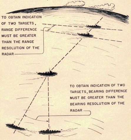
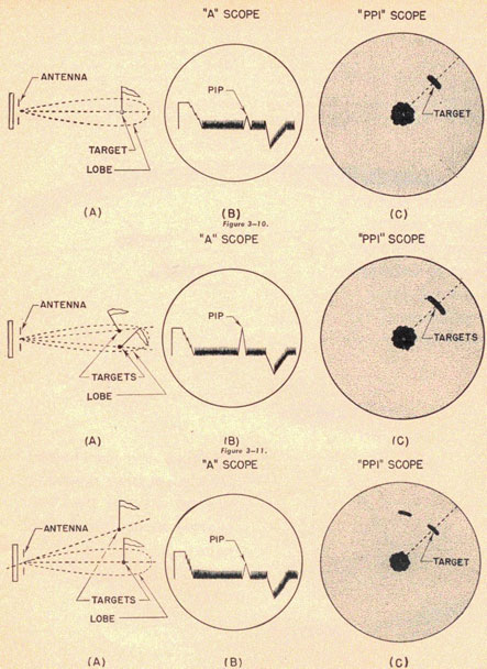
Estimating the number of ships.
Bearing and range resolution. Targets at the same
range will present separate pips only if they differ in bearing by a
certain minimum angular
distance. This angle is called the bearing resolution of the radar, and
it varies from set to set
(being proportional to beam width). On the other hand, targets on the
same bearing will present
separate pips only when they are separated in range by a certain minimum
distance. This
distance is called the range resolution of the radar, and it also varies
from set to set (being
proportional to pulse duration)
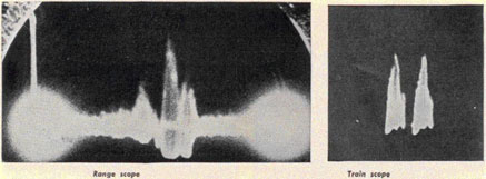
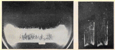
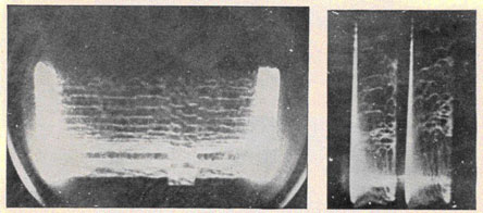
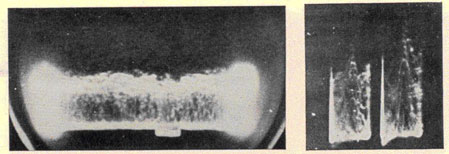
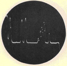
Figure 3-10B shows the picture appearing on the range scope with the
antenna trained on a
single target,
while figure 3-10C shows the picture appearing on the PPI under the same
conditions. Examine
carefully the pip's size. Now carefully cheek the pip's size on figures
3-11B and 3-11C with
the antenna trained on two targets within your beam, both at the same
range.
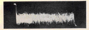
On the range scope, the pip is much higher as a result of more reflected
energy teaching your
antenna, while on the PPI, the pip is much wider. The pip is not deeper
(thicker), since the
time base represents only the range of the target. Figures 3-11B and
3-11C show only one pip,
since the targets were too close together for the bearing resolution of
the radar used.
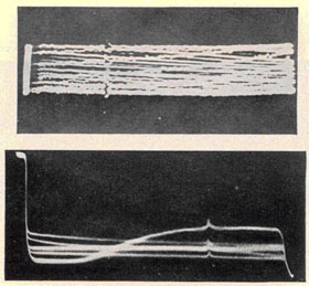
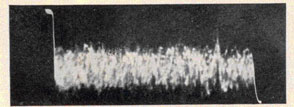
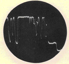
Figures 3-12B and 3-12C are the pictures appearing on the range and PPI
scope respectively,
when the targets are still at the same range, but with their bearing
difference great enough to
obtain bearing resolution, as indicated in figure 3-12A. Here, a new pip
will appear as the
antenna is trained to the bearing of each individual target; their energy
will not be cumulative
since difference in bearing is greater than the antenna's effective beam
width.
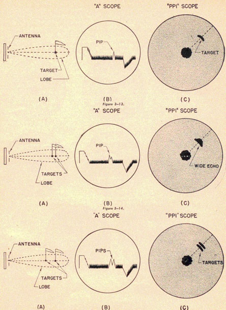
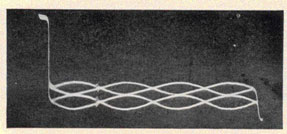
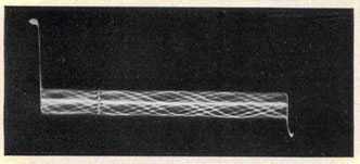
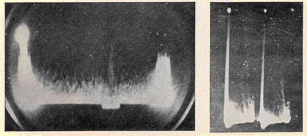
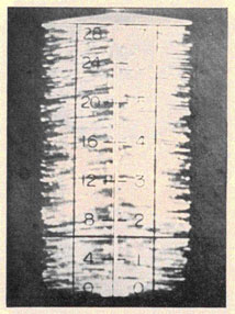
Next, consider figures 3-13B and 3-13C. Here again you see the antenna
pointing on only one
target, as noted in figure 3-13A. Compare these pips carefully with those
appearing in figures
3-14B and 3-14C. Notice that the pips in figures 3-14B and 3-14C are
deeper as a direct
result of a range difference between the two targets. Should the two
targets under observation
have even a greater range difference, the deep pip will appear split, as
shown in figures 3-15B
and 3-15C. Here, the number of individual peaks will indicate the number
of targets.
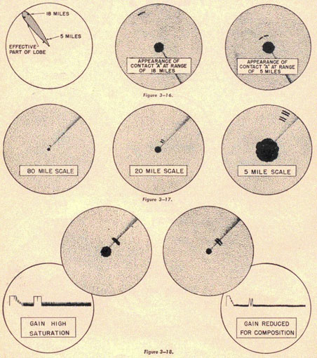
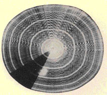
Effect of range on bearing resolution. As shown in figure 3-16, the
ability of a radar to
separate two targets close together in bearing improves as the range
decreases , because the
angular difference in their bearings is increasing. Notice that the two
ships are covered
simultaneously by the effective part of the lobe when at a range of 18
miles. On the other hand,
when the same two ships close to five miles, the effective part of the
beam cannot touch them at
the same time, and they can be seen as two separate contacts. The bearing
resolution angle, in
other words, intercepts a smaller distance at short range than it does at
long range. Keep
counting contacts as the range closes.
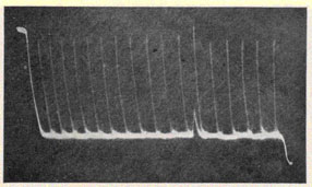
Effect of sweep length on range resolution. Due to the fact that pictures
are traced on scopes by a
relatively large spot of light rather than by a tiny point of light, a
certain amount of definition
is lost. Regardless of the range scale in use, the size of the electron
beam spot remains the same;
consequently, it becomes increasingly difficult for this beam to trace a
clear picture
3-12
PIPOLOGY
of the two contacts on the same bearing as they move closer to one
another on the scope.
Therefore, the longer the range scale, the closer the contacts will move
to one another on the
range axis and the more likely they will be to blend into a single
contact. This effect is more
noticeable on the PPI or "B" scope than on the "A" type.
The PPI drawings in figure 3-17 illustrate the point that a four-ship
contact may look like one
ship when
seen on the long-range scale, like two when seen on the medium-range
scale, and like four on
the short-range scale, due to improving resolution. Study composition on
the shortest scale
possible.
Effect of receiver gain on range resolution. The
range resolution will always be best when the gain control is turned low
enough to present
saturation. You cannot read composition on a saturated echo (one so high
on the range scope that
the top is squared off),
Figure 3-9. Bearing and range resolution.
3-13
RADAR OPERATOR'S MANUAL
Figure 3-12.
3-14
PIPOLOGY
Figure 3-15.
3-15
RADAR OPERATOR'S MANUAL
so turn the gain down momentarily when necessary. Do not make the mistake
of leaving it low,
since this will decrease the sensitivity of the radar, (See fig. 3-18.)
To help you get a clearer concept of resolutions, let us consider the
topic from another point of
view, analyzing the effect of both bearing and range resolution at the
same time rather than one
at a time as previously done.
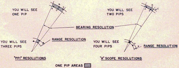
One-pip areas. The diagrams in figure 3-19 illustrate the fact that the
bearing and range
resolutions of the "A" scope are superior to those of a PPI on the same
radar. Furthermore, they
illustrate the size and shape of areas within which no resolution is
possible, let us call these
one-pip areas. Notice that the range resolution does not vary with range
as long as the same
range scale is used. Also notice that the width of the
Figure 3-18.
3-16
PIPOLOGY
one-pip areas increases with range, the bearing resolution expressed as
an angle does not vary
with range, but the actual width or intercept of this angle does
increase. Therefore, the one-pip
areas are narrow at short ranges and wide at long ranges. For any given
range, there will he a
one-pip area of a certain definite size and shape, and if you detect a
group of ships at that same
range, they will give only one pip (no matter how many ships there are)
if their disposition can
be completely fitted into this area.
Now let us consider the figure 3-19. The group of ships when at long
range just fits inside the
one-pip area of the PPI, and as a result only one pip will be seen on
that indicator (this would
be true of 300 ships too, if they were disposed within the one-pip area).
However, two pips
will be seen on the "A" scope because the one-pip area of that scope is
smaller and the
disposition cannot be contained by it. In this case targets A and D will
show as one pip which can
be resolved in range from another pip formed by B and C. Thus by using
the "A" scope you know
there are at least two contacts instead of the single one shown by the
PPI.
After this group of ships closes to a shorter range you will be able to
tell much more about its
composition. Even the PPI will then show three pips. Since B and D can be
enclosed by the one-pip area they will give only one pip. When B and D are in the no-pip
area, neither A nor C can
fit in it; therefore, they will be resolved, and three contacts will be
seen: A, B-D, and C. The "A"
scope again shows its superiority in the field of composition. Notice how
small its one-pip area
is at this range. Only one ship at a time can be enclosed by it, with the
result that four separate
contacts can be recognized, In other words
each contact can he resolved from the next in both range and bearing.
What is the significance of this discussion? For one thing, the
superiority of the "A" scope for
composition reading is established. Furthermore, you now realize that the
smaller the area
occupied by a disposition of ships, the closer you will have to approach
that disposition to tell
by radar how many ships are in it. Finally you realize the importance of
checking composition
frequently as the range closes. At any instant one pip may become several.
Incidentally, the reverse of this is true even in the case of a closing
contact, if the ships
comprising that contact suddenly form a smaller disposition. Radar
operators have reported
ships sunk, because they did not realize that there is more than one way
for two pips to become
one pip.
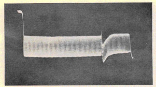
Estimating the number of planes.
One aircraft contact gives a narrow pip which bounces wildly and
irregularly. A large plane
echo, however, will bounce less erratically than a small one, just as a
pip from a large ship
will bounce less than a pip from a small ship.
Two planes will usually give a slightly wider pip (wider in range or
bearing), and the pip will
rise and fall more slowly and regularly. The echo of three or more planes
in formation will have
an uneven, jigging motion, distinctly different from two planes in that
it is not regular. The
echo will not decrease to or near zero, but will vary at near maximum
height.
The number of aircraft can be approximated in larger formations by
counting the number of
individual pips and multiplying that figure by three or four (this will
give only a rough
approximation of
Figure 3-19.
3-17
RADAR OPERATOR'S MANUAL
course). The size of raids can also be estimated, using the PPI. You may
become quite proficient
at this if you take every opportunity to check your estimates.
An air-group contact may represent planes at some certain altitude, or it
may represent a
"stacked raid" (planes coming at more than one level). If the group
contact divides somewhat so
that you can recognize two separate groups, try to determine whether or
not they fade at the
same range. If they do not, they are not at the same altitude.
General hints on composition.
Inasmuch as air-search radars can detect surface targets, and
surface-search radars can detect
air targets, a few hints on recognition of these targets will be of value.
Land targets :
1. Not moving according to geographic plot,
although the contact moves on the radar scope due to own-ships motion.
2. Pip does not bob like a moving target pip.
3. Should be at expected positions.
4. Usually cover greater area on screen than other targets.
5. Separate pips do not move relative to one another.
Ship targets :
1. Pip height bounces at fairly slow rate.
2. There are normally no fades except when range becomes too great.
3. Speed less than 50 knots (see RADFIVE for target speed determination).
4. Narrow tent-shaped pip compared with land, although a big rock may
resemble a ship in this
respect.
Plane targets :
1. Speed is greater than 50 knots.
2. Rapidly bobbing pip.
3. Fades appear periodically on long-wave air-search radars. (The reason
for this is explained
in Part 1.)
4. One plane gives a narrow, quickly bobbing
pip.
5. Two planes together give a regularly bobbing
pip.
6. A mass flight may give one or several large
(high and/or wide) rapidly bobbing pips. Sometimes it is possible to
count individual planes by
breaks in the peaks of pips.
FALSE CONTACTS
Many pips appear on radar scopes that are false in the sense that they
resemble ship or plane
pips but are not caused by ships or planes. Report them, but say that you
think they are false,
and give your reasons.
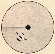
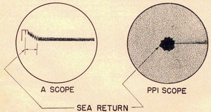
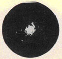
Sea return.
The pips shown in figure 3-20 are produced by the radar pulses reflecting
from nearby waves.
These pips are constantly shifting position, and appear as rough.
Figure 3-20.
3-18
PIPOLOGY
high grass. The rougher the sea, the stronger the reflection (called
sea-return) will be. In a
very rough sea, the sea-return may extend 4,000 to 5,000 yards in range
from you.
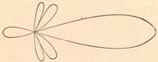
Minor lobes.
The beam of radio waves sent out is not perfectly shaped like a
searchlight's beam. Actually, if
we could view the beam as we can a light beam, it would appear somewhat
as shown in figure 3-21 (viewing it from above). We have the main lobe in the direction the
Figure 3-21. Major, minor, and back lobes.
antenna is pointing, and a series of smaller lobes, not wanted but
unavoidable, pointing in
various other directions. When these smaller lobes (called back and side
lobes) illuminate a
target they also produce echoes, especially if the target is large and
fairly close. These minor
lobes seldom reach out more than 6,000 or 7,000 yards, except when they
strike high land.
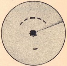
They produce a picture on the PPI as shown in figure 3-22.
Note that all pips are at the same range. The largest pip is the actual
target; all others are
minor-lobe echoes. The minor-lobe echoes may be eliminated by cutting
down the gain, but that
of course, may also eliminate other small targets from the screen,
Clouds.
The radar at times acts as a weather prophet since it indicates clouds,
fog, rain squalls, and
regions of sharp temperature differences. Some clouds are not visible to
the eye; they are called
ionized clouds, although this is a misnomer. Often an echo from a cloud
resembles an ordinary
pip from a surface target, and at night might lead to a wild goose chase"
if it were not
investigated further. Course and speed of the target should he determined
by tracking it. If its
course and speed agree with the wind's direction and speed you might
suspect it to he a cloud.
Unfortunately, upper air currents sometimes differ in direction and speed
from those at the surface.
Figure 3-22. Minor lobe echoes.
More positive identification may he obtained by training on the target
with the fire-control
radar to
Figure 3-23. Rain squall.
3-19
RADAR OPERATOR'S MANUAL
determine whether it is on the surface or has a position angle indicating
an air target.
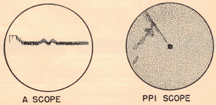
A rain squall or fog bank may usually be identified by the type of pip
produced on the screen. It
will be wide in bearing and thick in range; since neither rain nor fog
forms a solid reflecting
surface, the pip produced is of a fuzzy, lacy nature. A typical rain
squall might appear on the
range scope and PPI as shown in figure 3-23.
The sketches in figure 3-24 indicate the type of picture which will be
seen. If the interfering
radar pulses do not move, they may obscure target pips. Some sets are
provided with a front
panel control of the repetition rate, and any change in rate will cause
the interfering pulses to
move and keep moving. At times the intricate patterns produced on the
PPI may in themselves
be interesting, but the experienced operator becomes so accustomed to
such interference that
he hardly notices it.
Figure 3-24. Radar pulse interference.
Figure 3-25. Multiple-range echoes.
Radar pulses.
Often pips which move rapidly across the screen are seen: there may be
one or several. They are
usually caused by another radar transmitter of the same wave length, and
may have the
appearance of telephone poles as viewed from the window of a moving train.
At long ranges the radar interference will be picked
up only in the direction of the interfering radar transmitter. At close
ranges the interference
will appear at all hearings. Radar interference will always be picked up
at a range considerably
greater than the range at which a returning radar echo may be detected.
Hence
3-20
PIPOLOGY
you might pick up another ship's radar in this way long before its echo
appears.
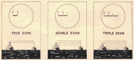
Double-range echoes.
Double-range (or double-bounce) echoes are most frequently detected when
there is a large
target at comparatively close range abeam. Such echoes are produced when
the reflected wave is
sufficiently strong to make a second or third round trip, as shown in
figure 3-25. Double-range echoes are weaker than the main echo, and appear at twice the
range. Triple-range echoes
are so very weak that they are seldom seen at all. You recall from Part 1
that these echoes are an
aid in determining zero-set errors in radars.
Second-sweep echoes.
Second-sweep echoes appear only on some radars (never on the SC, SK, SA,
but sometimes on
SC, Mk. 3, Mk. 4, and other sets with high repetition rate). They are
caused by echoes from
targets at long range; in fact, from such a tong range that the echo from
pulse 1 returns after
pulse 2, and the echo from pulse 2 returns after pulse 3, etc. Since they
must come from
contacts at a greater distance than that indicated on your scope, their
pips are usually smaller
than you would expect at the indicated range. Usually they will be from
land targets, since that
is about the only target that can be seen far enough away to appear as a
second-sweep echo. Find
out if there is any land in the direction of a suspected second-sweep
echo.
If you vary the repetition rate of your radar, the second-sweep contact
will move to a new indicated
range, whereas the range indicated for a legitimate first-sweep echo will
not be affected by
changes in repetition rate. The repetition rate of the SC radars is
variable, but do not under any
circumstances try to vary the rate of the Mk.3 or Mk.4, since such action
would upset the
accuracy of range calibration. In any event, this false contact is so
rare that you may never see
it.
Reflection echoes.
Reflection echoes are sometimes seen, due to the radar wave being
reflected from some surface
aboard your ship. It results in a contact at the correct range but the
wrong bearing. This type of
echo only occurs when the antenna is on a certain relative bearing. You
should know the relative
bearing of your particular installation which is subject to this fault.
Wakes.
The wakes of nearby large ships will he detected by your radar from time
to time, especially
during turns of the target ships, and when running at full speed. They
are small, ill-defined
contacts on the PPI, near to but astern of the ship contact causing them.
Miscellaneous objects on the surface.
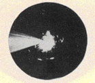
Unexplainable echoes, usually at very close range, may be from whitecaps
(beyond the sea-return in the direction from which the wind is coming), from birds, from
floating objects such
as large metal cans or shell cases, and from seaweed.
PPI INTERPRETATION
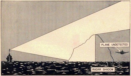
Radar shadows.
In order to visualize land nearly as radar "sees" it, imagine yourself
looking down on an area
from a point high in the sky above it, at about the time of sunset. The
beam of light from the low
sun illuminates the parts of land that a radar on the same bearing would
"see" but of course there
will be shadows in the hollows and behind the mountains. These same areas
will be in "radar shadows" and therefore not detected by the radar. So much for the points of similarity between these
two pictures. Now let us
analyze the differences.
Beam-width distortion and pulse-length distortion.
Two types of distortion are always involved in PPI presentation. One is
due to the diverging
beam of the radar, and can be calledbeam-width distortion.
3-21
RADAR OPERATOR'S MANUAL
The other is due to the fact that the pulse is not instantaneous
(although very short indeed), and
it can be called pulse-length distortion. Beam-width distortion results
in the widening of all
things detected by radar; that is, all contacts appear to spread to the
left and right of their
actual positions. The stronger the echo, the greater the spread. This is
more noticeable on long-wave air-search sets because of their wide beam width than it is on
micro-wave sets. The
result of pulse-length distortion is increased depth of target pips on
the range axis of the scope.
For example, a small navigation buoy may give a pip 300 yards deep on the
"A" scope. As you
probably have noticed on the PPI, contacts spread in bearing more than
they thicken in range.
This becomes increasingly apparent as range increases.
Have you ever noticed that a straight shore line often looks
crescent-shaped on the PPI The
effect is noticeable on any radar at times, but is most pronounced on
long-wave air-search sets.
The slight crescent-shaped effect is due to beam-width distortion. Notice
in the drawings of
figure 3-28 that the coast-line distortion is negligible at points where
the shore is at right
angles to your line of sight, but as this angle decreases, the shore-line
distortion increases is
shown, reaching a maximum at Various points of tangency.
Side-lobe ringing.
At times the crescent-shaped effect is so noticeable that according to
the PPI, you seem to be in
the lagoon of a coral atoll or land-locked harbor, when actually you are
off a fairly straight but
mountainous coast line. This complete ringing effect will be noticed only
on long-wave (air-search) sets; it causes much concern among fighter director officers and
others concerned with
air defense. This effect is due to a combination of two things. One is
the beam-width distortion
already mentioned and the other is side- and back-lobe contacts.
Low land.
Radar frequently fails to detect low-lying and gradually sloping land,
especially at long range.
This results in another distortion of a coast line.
Ships near shore.
Ships or rocks close to the shore may blend with it and either lose their
identity completely or
appear as a bump on the coast line. The effect is due, of course, to the
spreading of all contacts in
both bearing and range. A ship may hide from radar by getting very close
to shore at any point,
but the best place to escape radar detection would be at a point of
tangency near the shore (the
higher the better with relation to the radar's position).
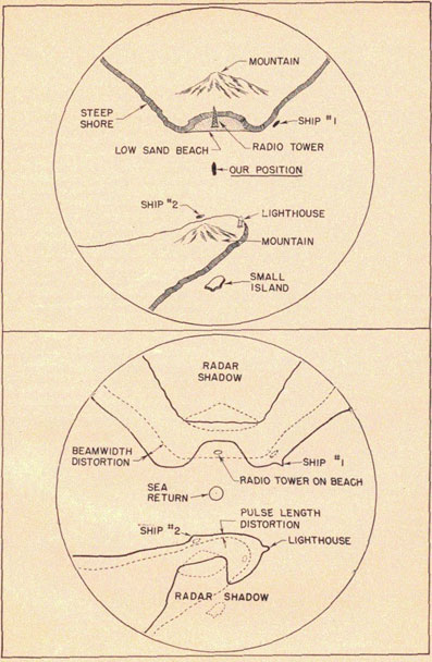
Figure 3-27. Radar shadow.
3-22
PIPOLOGY
Figure 3-28.
3-23
RADAR OPERATOR'S MANUAL
Consideration of these various factors, and reference to topographical
data on the land to be
approached, will help you to form a mental picture of what will appear on
the scope. Likewise,
it will be necessary for you to refer to topographical data to interpret
strange land masses. The
two drawings in figure 3-28 illustrate and summarize the various
distortions that have been
discussed. The first shows the actual shape of the shore line and the
significant topographical
details. Notice also the radio tower on the low sand beach, the two ships
at anchor close to shore,
and the lighthouse. The second drawing shows (in heavy line)
approximately how the land will
look on the PPI. The dotted lines represent the actual shape and position
of all targets. Notice
these things in particular:
1. The low sand beach is not detected by the radar.
2. The tower on the low sand beach is detected but it looks like a ship
in a cove. At closer range
the low land would be detected and the cove-shaped area would fill in;
then the radio tower could
not be seen without reducing receiver again.
3. The diverging radar shadow behind both mountains. Distortion due to
radar shadows is
responsible for more confusion than any other factor. The small island
does not show for this
reason. Notice also that the back half of the mountains does not show.
4. The beam-width distortion (the spreading of land in bearing). Notice
that it is maximum at
points of tangency. Look at the upper shore of the peninsula and notice
that the shore-line
distortion (due to beam-width distortion) is greater at the left than at
the right. This is because
the angle between the radar beam and the shore line is smaller at the
left than at the right.
5. Ship 1 looks like a small peninsula. Her contact has merged with land,
due to beam-width
distortion. If land had been a much better radar target than the ship,
the contact due to the
former would have completely covered that due to the ship.
6. Ship 2 also merges with the shore and forms a bump on it. In this case
she has merged with
land due to pulse-length distortion (range spread). Reducing receiver
gain might cause her to
separate from land if she was not too close to shore.
7. The lighthouse looks like a peninsula due to the fact that it gives a
better echo than the land it
is on, and consequently spreads more in bearing (due to beam-width
distortion) than the echoes
from land.
MISCELLANEOUS CONSIDERATIONS
Course changes.
In many cases you can tell when a target changes its course before this
fact is revealed by the
plot. The change is indicated by an increase or decrease in the strength
of the echo, and is due to
increased or decreased presentment. For example: a target may be seen
end-on, giving an E-2
echo, but when the same target changes course so that you are facing its
broadside, the echo
suddenly increases to E-4. You will not usually be able to notice any
difference in the echo
strength as a result of small changes in target course; therefore any
sudden, noticeable change
in the echo will indicate a substantial course change. You should report
this without delay, even
though you cannot tell which way the target has turned. The fact that it
has changed course at all
will often be significant.
Blind sectors.
You have been told that radar shadow always exists behind objects that
reflect radar energy.
Naturally then, unless your antenna is higher than any other part of your
ship, it is possible
that a blind sector may exist on some relative bearing due to the effect
of such radar obstacles
aboard your own ship as
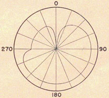
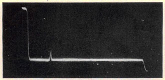
Figure 3-29. Graph showing blind sector.
3-24
DEFENSES AGAINST ENEMY RADAR COUNTERMEASURES
super-structure, masts, or other antennas. If you have a blind sector you
should know exactly where it is.
One way to check for blind sectors is to keep your antenna trained
exactly on some steady land
target while "swinging ship" through 360 degrees several times. It will be easy
if your radar is a true-bearing type, since the antenna will stay on the target as the ship
swings. A graph may be made
using polar coordinates, showing echo height versus relative bearing of
the chosen land contact.
It might be useful to attach a temporary scale to the A scope to assist
in determining the relative
strengths of the echoes. An illustrative graph is shown in figure 3-29.
Such a graph will enable you to estimate which relative bearings are
partially blind to your
radar. Several graphs should be made before the final pattern is
determined. If it is impossible
to utilize a land echo,
an approximation of the radiation pattern can be obtained by noting the
relative strength of sea-return from different bearings. The sea should be fairly calm, since a
heavy sea would give a
false indication of the pattern; that is, greater reflection would occur
from the wave fronts than
from the troughs regardless of the actual radiation pattern.
From the foregoing discussion it can be seen that there is more to
learning to be a to radar
operator than just studying the information in books. It is going to take
a lot of actual work on
the apparatus itself, but operating time alone means nothing unless you
get into the habit of
thinking, observing, and remembering, making predictions and checking
them, and looking for
small details. Radar operating is an art.
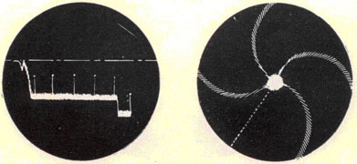
DEFENSES AGAINST ENEMY RADAR COUNTERMEASURES
INTRODUCTION
The enemy has two purposes in using radar countermeasures: first, he hopes
to prevent us from
obtaining any accurate or useful information about his forces by the use
of our radars; and
second, he wishes to get information about our forces by listening to our
radars. The radar
countermeasures methods that may be used in accomplishing these purposes
are of four types:
interception, jamming, deception, and evasion.
Interception is the detection of radar signals by the use of a special
receiver. By this means, the
enemy learns of our presence in his vicinity, obtains an approximate
bearing on our position,
and he may determine some of the characteristics of our radars.
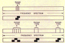
Jamming is the deliberate production by the enemy of strong signals for
the purpose of hiding
his movements or position from our radar by obliterating or confusing the
echoes on our
indicators. The jamming signals may be produced by a modulated radio
transmission, which is
electronic jamming, or by echoes returned from many small metal strips,
termed Window.
Deception is the deliberate production by the enemy of false or
misleading echoes on our radar
by the radiation of spurious signals synchronized to the radar, or by the
reradiation of radar
pulses from extraneous reflectors. Small targets may be made to appear
like large ones or
echoes may be made to appear where no genuine target exists.
Evasion consists of tactics that are designed to take advantage of the
limitations of our radar to
prevent
or postpone radar detection, or to avoid revealing the true position of
an attacking force. If
attacking enemy planes take evasive action, it may be impossible to
determine the height at which
they are flying, or the planes may be detected too late for an adequate
defense to he made ready.
VULNERABILITY OF RADAR TO
COUNTERMEASURES
Interception.
Radar pulses become weaker as they go away from the radar. Only a small
fraction of the energy
of these pulses is reflected by the target. This small amount of energy
becomes even weaker in
returning to the radar. At ranges where the pulse is too weak to return a
useable echo, the pulse
may still be strong enough to be detected by a receiver. Thus, if the
enemy has receivers for
listening to our radars, he will be able to detect our forces at ranges
greater than those at which
we can detect him by radar. In addition to detecting our radar, the enemy
can also determine our
radar frequency, pulse repetition rate, pulse duration, and whether or
not lobe switching is
used, and use these data for subsequent countermeasures operations. It
may also be possible for
the enemy to estimate the size of the force near him by noting the number
of signals
intercepted, or to analyze the intercepted signals as a means of telling
whether or not he has
been detected by our radar.
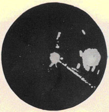
The coverage of a radar can be charted by intelligent use of intercept
receivers if the radar
operator
3-25
CHANGE NO. 1
RADAR OPERATOR'S MANUAL
Figure 3-30. Illustration of why electronic jamming is often many times
stronger than a radar echo.
is not careful of his operating procedure. For example, one of our radar
reconnaissance planes
charted a Jap land-based radar completely by flying toward it at various
elevations and on
various bearings. The Jap operator stopped his radar beam on the plane as
soon as it was
detected and followed its motion as long at it was in the field of view
of the antenna. Thus the
complete coverage of the radar was found by interpretation of the
intercepted signals. Our
radars are also vulnerable to such reconnaissance if the operator stops
his antenna on each
target as it is detected. Therefore, to avoid giving information to enemy
snoopers, keep the
antenna rotating.
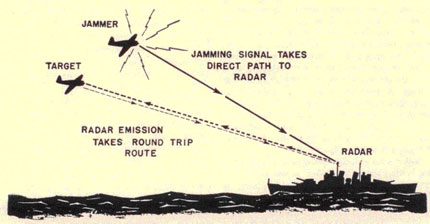
Jamming.
Jamming signals are generated by transmitters that may be carried in
aircraft, on ships, or
installed at land bases. The transmitter is operated as nearly as
possible on the frequency of the
radar which it is desired to jam. The signal from the jamming transmitter
is usually much
stronger than the radar echo, since the jamming travels directly, as
opposed to the round-trip
path taken by emission from the radar. A strong jamming signal may
overload the radar
receiver, which necessarily has been designed to be a very sensitive
instrument, and therefore
it may be rather susceptible to overloading.
Figure 3-31. Jammer located on target. Target said to be self screened.
3-26
CHANGE NO. 1
DEFENSES AGAINST ENEMY RADAR COUNTERMEASURES
Very often a ship may try to conceal itself from radar detection by
carrying a jammer. This
kind of jamming, which is illustrated in figure 3-31, is called self
screening. If other ships
are in company with the jamming ship, the problem of detecting them may
be complicated by
the fact that the jamming and echo do not come from exactly the same
place. Irrespective of the
position of the jamming ship relative to the target vessel, a weakness of
electronic jammers is
that they are not effective within a certain minimum range. When
approaching the target, you
will first pick up the jamming signal, owing to its high strength. At
normal radar range, both
jamming and echo from enemy ship will be present, although the jamming
may be strong enough
to obscure the echo. However, as the range closes, the strength of the
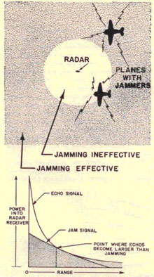
Figure 3-32. Electronic jammers ore less effective at short ranges than
at long.
echo signal increases much more rapidly than the
strength of the jamming signal. A point is finally reached where the
target pip shows up clearly
through the jamming. The range at which this occurs may be between 2 and
8 miles, depending
upon the size of the enemy ship and the strength of the jammer. Figure
3-32 shows this
condition as related to the range of an approaching aircraft equipped
with a jamming
transmitter.
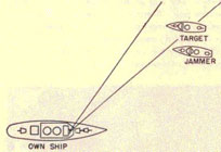
When a jammer is not on every vessel to be screened, it is difficult to
prevent detection of the
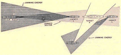
force from every direction. For example, in figure 3-33 a very
exaggerated case is illustrated.
Enemy ships 3 and 5 are equipped with jammers and their mission is to
conceal the force. Since
enemy ships 3, 4, and 5 all bear the same from friendly ship 1, they are
concealed by the
jammer on 3. However, a picket ship at 2 may be able to range on some of
the targets in spite of
the attempt by enemy ship 5 to jam him. Even though some of the ships in
a task group are
hopelessly jammed, others may be relatively unaffected. Therefore, keep
all the radars in
operation because the situation may improve as the dispositions of the
two forces change.
An aircraft carrying a jammer might pass through a fade zone while echoes
from the ship he is
protecting are unaffected. This would cause a sudden improvement in echo
strength over the
jamming, perhaps making more readable echoes that were obscured. This
same effect may occur
when the jammer is on the ship to be screened, since the antenna pattern
of a surface search
radar also is broken into many lobes and nulls by reflection of the
radiation from the water. The
jammer antenna must direct its radiation directly into the small area of
the radar antenna,
while the radar antenna needs only to cause its pulse to hit some part of
the large area of the
enemy ship to get an echo back. At ranges where the jammer antenna is in
a null of the radar, as
in figure 3-34, the jamming is ineffective, but an echo is returned from
the superstructure of
the enemy ship because the lobe below the null strikes the ship. Thus, it
is necessary to keep
the radar operating, and to maintain a close watch on the scope when
jamming is encountered,
because the jamming effectiveness may suddenly be reduced.
Off-target jamming is seldom produced deliberately; it usually occurs
because the disposition of
the jamming ships changes relative to the vessels they are attempting to
screen. Jamming of
this type imposes no special problem for most search radars, but if the
radar is one that
employs lobe switching, bearing
3-27
CHANGE NO. 1
RADAR OPERATOR'S MANUAL
Figure 3-33. Jammer is on same bearing but not on board target. Radar
located on friendly ship at 2 is probably free of jamming.
errors may be produced. The error arises from the fact that the
jamming does not affect
both lobes equally, so that the matched-pip condition may appear at the
wrong bearing. In
radars like the SM and SP, jamming can also produce serious errors in the
height measurement.
These inaccuracies are greater in some radars than in others because of
the nature of the
receiver circuits used. In general, however, the errors in angular
measurement that off-target
jamming produces in lobe-switching radars can be reduced by operating the
receiver at the
lowest gain setting that allows the pips to be clearly visible. When
range information only is
desired, better results are obtained with lobe-switching "off". No
bearing inaccuracy should
occur when the jammer is on the target (self-screening) or on the same
bearing as the target.
In order to become aware of possible bearing inaccuracy, it is necessary
to determine whether
the jammer is on or off the target bearing.
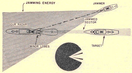
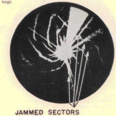
If the side lobes of the antenna are large in size, jamming can be
received from directions other
than the one in which the main lobe is pointed. In some cases, the
jamming received in this way
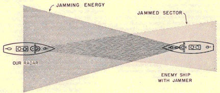
may conceal a target which is not on the same bearing as the jammer. For
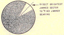
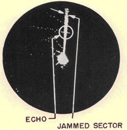
example, in figure 3-35 the radar on the friendly ship is jammed by the off-target jammer so
that neither enemy
ship can be seen on the PPI. Note that there are three distinct jammed
sectors on the
accompanying PPI screen, produced by reception in the three lobes as the
antenna rotates. If the
jamming is not too strong, the sectors of jamming caused by side-lobe
reception can be reduced
in intensity by reducing the receiver gain. The target in figure 3-35
might be made visible by
this simple adjustment.
The relative ineffectiveness of off-target jamming, except against
lobe-switching radars,
suggests maneuvering until the jammer is in an unfavorable position.
Figure 3-34. Jamming ineffective because the jammer antenna is in radar
null.
3-28
CHANGE NO. 1
DEFENSES AGAINST ENEMY RADAR COUNTERMEASURES
Figure 3-35. Jamming reception in side lobes from off-target jammer.
The enemy will monitor both his own jamming and the signal that he is
attempting to jam so that
he will know if either changes frequency enough to make the jamming
ineffective. He may be
expected, then, to train his jamming antenna for maximum jamming, and it
will be very
difficult for a single ship to maneuver in such a way that the jamming
effectiveness will be
decreased. However, it is always well to search the areas around the
jammed sector in the hope
that either the enemy operator is not alert or that some of the ships
that he is trying to conceal
will have strayed outside the zone of effective concealment. The
possibility that the jamming is
being used for deceptive purposes must be considered. Therefore, a
thorough search must be
maintained throughout the full 360 degrees because the jamming may be sent out
to attract our
attention to a sector away from the direction from which the enemy plans
to attack.
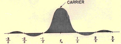
Microwave radars are less vulnerable to electronic jamming than long wave
types. The narrow
beam width allows targets to be seen close to the jammer bearing, and the
concentration of high
power in a single direction makes for high signal strength relative to
the jamming. Adequate
jamming is hard to produce against microwave radars because it is
difficult to develop high
power at these frequencies.
A radar operating at peak efficiency is far less susceptible to jamming
than one which is out of
adjustment.
This is especially true with regard to the transmitter-weak or
erratic emission
seriously reduces the chances of the echo signal strength being strong
enough to override the
jam. Report any falling off in equipment performance to the technician.
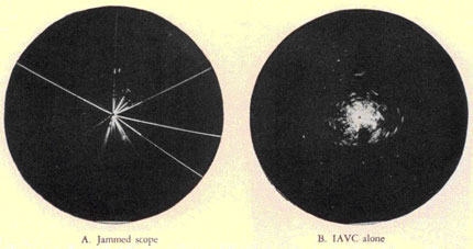
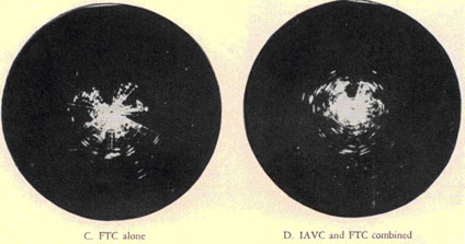
The A scope is less vulnerable to jamming than the PPI or B types, and
therefore should be used
when jamming is encountered. However, in the case of noise jamming, the A
scope is little
better than any other type of indicator, but it will be found more useful
against most other
types of jamming. PPI or 13 presentations are preferred only when it is
desired to find the
bearing of the jammer. It is not desirable to keep the antenna stopped
for long intervals while
trying to read through jamming on the A scope. All-around search must
always be maintained.
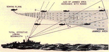
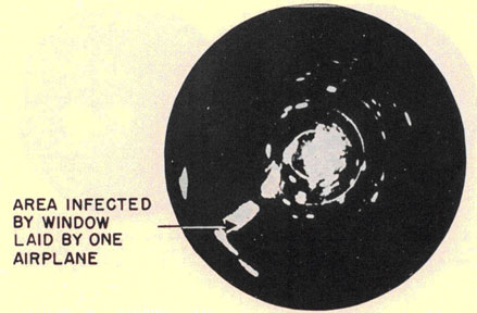
Jamming can also be accomplished by the dispersal of many strips of
reflecting material, called
Window. Since Window jamming consists of a cloud of particles that occupy
a definite place in
space, the vulnerability of radar to this type of jamming is different
from the vulnerability to
electronic jamming. Unlike cases in which electronic jamming is employed,
the location of
Window relative to any targets which it is supposed to screen is
continually changing. Window
moves with the wind at a speed approximately 2/3 that of the wind, while
the speed of the enemy
ship may be greater or less than the speed of the wind. If the Window
area is not large, the
enemy
3-29
CHANGE NO. 1
RADAR OPERATOR'S MANUAL
will have difficulty in staying in the Window-infested area because the
Window is hard to see in
the air. Watch for stragglers outside the infected area. Often they will
appear on the windward
side of the Window blob.
Window produces pips that are quite similar to those from real targets,
whereas electronic
emissions fill the scope screen with patterns totally unlike those
normally encountered. Also,
the reflected signals from Window will occupy only a portion of the
trace, while electronic
emissions cover the entire sweep.
The first indication of an impending raid may be Window pips on long
range search radars, so
that the jamming may work against the group responsible for it. With fire
control or height-finding radar, on the other hand, properly distributed Window can ruin
the accuracy of
determination of bearing and height. Because Window can ruin the accuracy
of AA fire control
radar, the principal use of Window has been against this type of radar as
a means of escaping
from AA fire after an attack.
If the enemy intends to infect a large area with Window to prevent search
or fire control by
radar, he will drop packages of it while flying a course that will
provide good coverage. A single
plane may fly a flat spiral or a figure-of-eight course; when several
planes are working
together, they may fly straight parallel courses, dropping packages of
Window at periodic
intervals. Surface craft may infect smaller areas by firing Window-filled
shells or rockets.
However, to be effective in concealing targets within the Window cloud,
the packages must be
dropped at close enough intervals that each bundle will not exist as a
separate cloud, but that all
the Window bundles will blend into one large cloud. The better the range
and bearing resolution
of the radar, the closer the Window must be sown to conceal the targets
within the cloud.
Deception.
Although it is possible to deceive radars by the use of electronic
devices, the necessary
equipment is difficult to design and operate. Test operations using
electronic deception have
indicated that the results seldom are good enough to warrant the trouble
involved. Since the
enemy faces a great problem in this field because we have more radar on
more frequencies, it is
unlikely that electronic deception will be encountered to any great
extent.
However, the use of mechanical devices for deception is entirely
feasible, and both the Germans
and
the Japanese are familiar with these deception techniques. For example,
the Japs have equipped
sampans with reflectors, so that they appear to our radars like large
craft. The sampans are
sent out in advance of a convoy, on courses calculated to lead our ships
well out of the way by the
time the real targets arrive. Other types of reflectors may be floated or
suspended from
balloons, and designed to give false echoes like those from submarine
periscopes, surface
vessels, or aircraft. Many of these devices produce echoes that seem very
similar to genuine
echoes in their behavior on the scope. Often the only way of revealing
the false nature of the
deception echo is to plot its track, since most airborne mechanical
devices drift down wind at a
speed somewhat less than wind speed. Thus, radars are very vulnerable to
attack by deception
for at least a short period of time. Often this short time is long enough
to permit enemy planes
to get out of gun range.
Evasion.
Low-frequency radars, such as the SK and other air search sets, can not
detect low-flying
targets at long range, because the antenna pattern is such that the beam
does not provide good
low cover. The enemy is quite aware of this shortcoming and his air
strikes frequently approach
"on the deck". Air-search radars are not able to detect changes of
altitude nor are they able to
detect aircraft flying over land with any certainty. The Jap knows these
limitations too, and
makes full use of them to avoid detection by radar. These failings are
serious, but they will soon
be remedied by new equipment that is being produced.
DISTINGUISHING JAMMING FROM INTERFERENCE
Interference is caused by the reception of confusing signals accidentally
produced by the effects
of either friendly or enemy electrical apparatus and machinery, or by
atmospheric phenomena.
Interference should not be confused with enemy countermeasures.
Accidental interference from many types of electronic gear and electrical
machinery has been
noted on radars. The signals may enter the radar receiver by shock
excitation of radio antennas
or guy wires, through the power line, by way of inter-connecting cables
between various units,
or because of inadequate shielding of the radar equipment. It is
difficult to predict the effects
these signals will have on radar operation. In some cases accidental
interference may
3-30
CHANGE NO. 1
DEFENSES AGAINST ENEMY RADAR COUNTERMEASURES
be confused with deliberate jamming attempts. Methods of distinguishing
between the two are
outlined in the following.
Internal equipment faults. Cluttered scope patterns caused by internal
faults in the equipment
may be distinguished from jamming or external interference because the
scope pattern remains
the same regardless of the direction in which the antenna is trained. If
trouble persists, call the
technician. However, with strong jamming the same effect may be observed
if the receiver gain
is not reduced.
Interference from other gear aboard own ship. It usually is possible to
take a bearing on
interference of this type. The relative bearing will always remain the
same, but the true
bearing will change with changes in the ship's course. If both bearings
change, the trouble is not
on board.
Pulse interference from other radar. Pulse interference causes light,
tall pips on A-scope
screens. These pips move back and forth along the trace in a random
manner, giving the pattern
the name "running rabbits". The spacing between pulses is usually much
larger than the width
of the pulses.
It is possible to take bearings on pulse interference from other radars
in the same frequency
band and having approximately the same pulse repetition rate. At short
ranges, the indications
appear over a large arc of antenna train. The usual method is to consider
the center of the arc as
the correct bearing, instead of training for maximum strength or
distinctness of the signal. This
system has been used to home on ships in convoy or on shore installations.
Pulse interference on the PPI results in a series of broken spirals.
Under normal conditions,
neither this pattern nor the one on the A scope causes serious difficulty because
the pips are
considerably more distinct than the interference, and because of its
prevalence, operators soon
become familiar with it. However, if the effect is found annoying, it may
be minimized by
changing the pulse repetition rate of own radar until the most easily
read pattern is obtained.
Interference from radio transmitters, beacons, etc.
Keyed CW may be read as dots and dashes. Rotating the radar antenna may
or may not produce
any difference, depending on how the interference is getting into your
radar.
Radiotelephone transmitters on board the ship
sometimes produces interference, but they may be distinguished by one or
more of the methods
discussed in the preceding paragraphs. This same type of interference
coming from nearby
ships may sometimes be very confusing to the operator. Therefore, every
effort should be made
by the operator to learn to identify it so that he will not confuse
communications interference
with enemy jamming.
Spark interference caused by commutator or ignition sparking appears on
the A scope as a
series of narrow, regularly spaced pulses. Interference from spark
transmitters, diathermy
apparatus, etc., will produce wider pulses, more closely spaced.
Generally the train of
interfering pulses will move across the screen. Spark interference may
blank out the screen of
PPI scopes in one or several sectors, depending on the signal strength.
Atmospherics. Returns from rain clouds or other atmospheric condition are
not likely to be
confused with transmission jamming. They are, however,
Figure 3-36. Interference from other radars- "running rabbits".
3-31
CHANGE NO. 1
RADAR OPERATOR'S MANUAL
somewhat similar to Window jamming. The pips produced by storms are often
lacy in character
on A scopes and may occupy quite a large portion of the
Figure 3-37. Interference produced by keying of radio transmitter on
board ship. Note
appearance of dots and dashes and non-directional effect produced. In
this case the interference
is not entering by means of the radar antenna, but directly into the
radar receiver itself.
screen. They show but a slow change in range. The appearance of both
cloud and Window echoes
differs from that of genuine echoes in the amount of beating that becomes
apparent when the
receiver gain is reduced, and the motion of the echoes always agrees with
the prevailing wind
direction. On the PPI, a storm will be indicated by a filled-in area
having less definition than a
genuine target. Some thunderstorms (the isolated convection type that
occur in summer) give
solid echoes surrounded by a cloudy haze. These echoes can be wrongly
interpreted as real
targets.
Lightning has been observed to produce large pulses on P band radar. St.
Elmo's fire has also
caused severe interference with P band radar on occasion.
CLASSIFICATION OF TYPES OF JAMMING
The two general classes of jamming are (1) the electronic type, in which
use is made of a radio
transmitter, and (2) mechanical or Window jamming.
Electronic jamming.
Types of electronic jamming may be classified according to the nature of
the emission employed
by
Figure 3-38. Atmospheric Interference.
3-32
DEFENSES AGAINST ENEMY RADAR COUNTERMEASURES
the enemy. Any kind of transmissions can he used, although with varying
degrees of
effectiveness. The list includes unmodulated continuous wave (CW),
frequency or amplitude
modulated CW, pulsed signals, and mixtures. The modulation frequencies
may be high or low,
and either synchronized or not to the pulse repetition rate of our
radars. We may expect a wide
variety of different patterns to appear on our radar scope screens,
depending on the particular
type of signal the enemy is sending out. Special equipment
is needed to identify the exact nature of these emissions. However,
the operator can often
obtain enough information from a particular scope pattern to make a good
guess as to what AJ
measures to apply without delay. Also, it is of obvious benefit to the
Navy to receive prompt
reports on the kinds of jamming being employed by the enemy.
The first general characteristic the operator may easily note about
modulated transmission
jamming is whether it is synchronous or nonsynchronous.
Synchronous jamming refers to signals which are modulated at an exact
multiple of the pulse
repetition rate of the radar against which they are being used. Thus, if
your equipment is
operating on a PRR of 60 cycles and the jammer is modulated at four times
that,
or 240 cycles, the jamming is synchronous. This produces a stationary
pattern on radar
scopes. Jammers not modulated at an exact multiple of the radar PRR are
called non-synchronous, and produce patterns which traverse the screen, causing
blurring. An
intermediate condition, known as semi-synchronism, results in an erratic
stop-go motion.
Noise is the only type of modulated jamming which cannot be synchronized.
A second consideration when attempting to distinguish between types of
jamming is the
approximate determination of the modulation frequency of the jammer. Jamming
modulation frequencies may
generally be classified as low, medium, or high.
On short range scales, or when using an expanded sweep, the electron beam
which traces the
time base moves much faster than on long range scales. This means that
for a given type of
jamming signal, the pattern will be less complex when the indicator uses
a short range scale.
Changing the range scale has the same effect as changing the frequency of
the jamming
modulation, so that what appears to be high-frequency jamming on a long
range scale may look
like low-frequency on the short scale. It is necessary, therefore, to
specify the particular
range scale in use when describing a jamming signal.
Figure 3-39. Synchronous and non-synchronous jamming. In (A), the same
portions of the
jamming signal waveform appear during each sweep an the radar scope
causing a stationary
pattern. In (B) the jamming is an different port at cycle during
successive sweeps. This
produces blurring an the scope screen.
3-33
CHANGE NO. 1
RADAR OPERATOR'S MANUAL
Figure 3-40. Effect of same jamming with different sweep times. The
pattern in the tong range
will appear to be more complex, because a greater portion at the
modulation cycle will appear.
An estimate of the effect of the jamming modulating frequency may be
learned by studying the
following sketches and their captions. A range scale of approximately 40
miles has been
assumed, except where otherwise noted.
Figure 3-41. The PPI in the presence at jamming.
The text which follows is concerned almost entirely with type A scopes,
because PPI and B
presentations are less useful for identifying jamming as they react in
nearly the same manner
to all types. However, a few points on the behavior of PPI scopes may be
noted. They respond to
non-synchronous jamming by showing one or more bright pie-shaped
sectors. If more than one
sector appears, the brightest is due to the major antenna lobe and the
others result from minor
lobes. An overloaded radar receiver is indicated by a reverse or
"negative" presentation, with
the jammed sectors dark on a light, speckled background. If the jamming
signals are
synchronous or semi-synchronous, striations (lines) show up on the screen
within the jammed
sectors.
Unmodulated CW jamming. Weak unmodulated CW jamming (or strong jamming at
low gain
control settings) causes an increase in both signal and noise level on
the A scope. The trace may
become distorted, (figure 3-42B), as the radar antenna first comes into
and as it leaves the
jammed sector. If the antenna were stopped in the jammed sector, the
trace would assume a
position along the normal base line. It will be noted that the pip is
double sided and is more or
less "filled-in" depending on how close the jammer frequency is to our
radar frequency. As the
jamming becomes stronger, both the grass and a single-sided pip may
appear below the baseline
(inverted). Finally, as shown in C, complete overload occurs, wiping the
trace clean of both pip
and grass.
3-34
DEFENSES AGAINST ENEMY RADAR COUNTERMEASURES
Figure 3-42. Unmodulated CW Jamming.
Unmodulated CW jamming is seldom used, although similar effects may
appear due to accidental
interference from radio equipment. Often when a small percentage of
modulation is used on the
jamming carrier wave many of the effects of unmodulated CW will be
apparent on the indicator.
Low-frequency amplitude-modulated CW jamming.
Somewhere within this region, depending upon the sweep time, the effect
known as "tramlines"
will occur. Tramlines appear as a number of adjacent, sometimes crossing,
horizontal baselines
on the A scope. The reason for the multiple pattern is that successive
traces are deflected
vertically different amounts by the jamming modulations. The target echo
will appear on each
trace, and it may be double-sided or inverted, as in CW jamming. If
unsynchronized, the
tramlines move up and down, so as to seem to breathe.
Medium-frequency amplitude-modulated CW jamming. The A-scope presentation produced by this type of jamming is
predominantly vertical,
even on short range scales. As the frequency is increased, the horizontal
or crossing-line
characteristic of low-frequency modulation gives way to more evenly
spaced, upright
indications, usually of constant amplitude. When the pattern is
synchronous or semi-synchronous, it is sometimes called "basketweave". The non-synchronous
condition is evidenced
by blurring, with lines or shading at regular intervals. These do not
block out the target
indications which run up through the jamming as a vertical line or series
of pips which are
atop each other, and have greater definition than the rest of the
pattern. The echo will also
appear on top of the jamming pattern if the gain control is adjusted so
that saturation is not
occurring. Care should be taken that the earn is not reduced so much
that signals will not appear if for any reason the effectiveness of the
jamming is suddenly
reduced. In figure 3-44 (A) the pip is double-sided, the grass is riding
the modulation, and the
gain has been adjusted so that saturation is not occurring. B shows a
modulation frequency about
twice that of A. Saturation is occurring so that the pip does not appear
above the jamming
pattern, and the normal -receiver grass is not riding on the pattern.
This is not dependent upon
the modulation frequency, but rather upon the relative strength of the
jamming with respect to
the echo. The grass could ride on either modulation pattern. If the
jamming were not
synchronized, it would probably be difficult to see much difference between
these two modulating
frequencies.
High-frequency amplitude-modulated CW. The
pattern obtained from this type of jamming is of the vertical type
described under medium
frequency and cannot readily be distinguished from it when the jamming is
non-synchronous.
The echo will have more of the appearance of riding on top if saturation
is not occurring, and the
lines of shading will be closer together.
Frequency-modulated CW jamming. Frequency-modulated jamming is not
distinguishable from
amplitude-modulated types except in the special cases of
Figure 3-45. Low-frequency, wide-band FM jamming.
3-36
CHANGE NO. 1
DEFENSES AGAINST ENEMY RADAR COUNTERMEASURES
Figure 3-46. Pulse jamming.
low-frequency, wide-band, FM. This produces "cobs" or "bells", on an
A-scope screen. These
can be fairly confusing if they are moving across the screen at a slow
rate. However, an echo pip
remains visible as a break in the trace, or by riding the bells.
Pulse jamming. Pulsed jamming transmissions are usually sent out at many
times the pulse
repetition rate of our radars, so as to cause a number of high vertical
pips on the screen. These
pips are usually wider than echoes, move together, and are evenly spaced.
They may look like a
picket fence, or a fine tooth comb, the indications becoming closer
together as the jamming
pulse rate is increased. The name "railings" has been given to this type
of jamming.
It is possible to see echoes through railings that
are moving across the screen rapidly, as they do when not synchronized
to the repetition rate
of the radar. The effect is similar to looking through a picket fence
white traveling past it. If
the jamming is partially or entirely synchronized, the pattern shows
little or no motion, and
echoes are harder to, identify but can be found on the baseline and
possibly on top of the
jamming signal. Railings should not seriously interfere with radar
operation, unless they
overload the receiver completely.
Mixed jamming. Two or more different kinds of jamming may be sent out
simultaneously. The A
scope will then exhibit the characteristics of each of the particular
types. For example, a
variety of "German mixture" is made up of a combination of
Figure 3-47. Random-noise modulated jamming.
3-37
CHANGE NO. 1
RADAR OPERATOR'S MANUAL
low- and high-frequency amplitude-modulated CW. The high-frequency
modulation gives a
vertical, closely-spaced, and usually blurred presentation higher up on
the screen.
Noise jamming. Noise jamming produces abnormally high grass on A scopes
without increasing
the level of the desired signal. If the height of the grass is several
times that of the echo, it is
very hard to work through: With the regular patterns produced by other
types of electronic
jamming, it is usually possible to adjust the radar receiver controls so
as to make the target
pip produce some irregularity in the picture, which can then be ranged
on, but the random
nature of noise does not permit this. It is regarded as the most
effective type of jamming, and, if
sufficiently strong, very little can be done to combat it. However,
effective noise modulation is
the hardest to obtain technically, and unless it is good it may be as
easy to work through as high-frequency modulated signals.
Window jamming.
Mechanical jamming by means of Window is now being employed by the enemy
to a much greater
extent than any kind of electronic jamming. However, this situation is
changeable, making it
important to learn anti-jamming measures against both general
types.
The name Window probably results from the fact that the material
originally consisted of
squares or oblong pieces of aluminum foil. When this foil was dropped by
an airplane, the light
reflections looked like those from many windows. It was found later that
more efficient use
could be made of a given amount of foil by cutting it up into narrow thin
strips. The Window now
used consists of such strips which are packed together in bundles when
carried in an aircraft
and which disperse when dropped. The
strips are cut approximately one-half wavelength long with respect to the
frequency of the
radar they are to be used against. Mixed Window cut to two or more
different lengths
corresponding to the frequencies of several radar types is sometimes
used. The strips may or
may not be paper-backed.
The first operational use of Window was in July 1943, when 700 British
bombers dropped
2300 tons of bombs and 30 tons of Window in a raid on Hamburg. A lane or
corridor 40 miles
wide and 80 miles long leading into the target was infected with the
material. As a result,
bomber losses were much less than experienced on a previous, similar raid
where no Window
was used. Since then most combatants have used Window in attacks on land
and sea forces.
Window dropped by aircraft first appears as a series of pips trailing out
from behind the
sowing plane. The indications closely resemble those from aircraft,
except that Window gives a
very rapid beating effect in contrast to the steady rhythmic beat of real
aircraft targets. This is
because the strips flutter as they drift downward. When a very large
amount of Window is
released, the signals saturate a sizeable portion of the range scale.
(See between 1 and 2 in
figure 3-48 A). The characteristic beating causes minute oscillations or
"ripples" in the trace
where it is not saturating. Later, individual pips are seen, as in B.
These become broader, more
ragged, and less like actual targets as time passes. They occupy a
greater portion of the trace
when the material disperses, but show only a very slow change in range.
Window drifts
downwind at approximately two thirds of the wind velocity. It falls at
about two to three hundred
feet a minute. Therefore, an important thing to remember about Window is
that i t remains
relatively motionless compared to an airborne target. On PPI scopes,
Window appears as an
island or cloud-like mass which gradually spreads out, and
Figure 3-48. Typical Appearance of Window jamming.
3-38
CHANGE NO. 1
DEFENSES AGAINST ENEMY RADAR COUNTERMEASURES
changes range in the direction of the wind. (See figure 3-48 C.)
The length of time Window will remain on our scopes depends on the
altitude from which it is
released. When dropped from 10,000 feet, it may be troublesome for as
long as thirty minutes
on air search radars. If dispersed by projectiles at low altitudes to
screen shipping, the time is
much less.
Other Mechanical Jamming. On frequencies below 200 megacycles and in the
microwave region,
long streamers of reflecting material are used in preference to short
strips. These streamers
are usually parachute supported, and are released in the same manner as
packages of Window.
This material is called Rope and produces a large echo having a lower
rate of flutter than
Window.
CLASSIFICATION OF DECEPTIVE COUNTERMEASURES
Window as a deceptive device.
One of the most important uses of Window is to decoy or otherwise deceive
the opposing force. It
will serve this purpose in a number of different ways. One deceptive use
of Window is to create
false echoes for the purpose of weakening our defense. In this case a few
enemy aircraft make a
low-altitude approach to escape detection by long range search radar.
When within radar range,
they climb to higher altitude, drop a considerable quantity of window,
and then retreat in the
same manner in which they approached. If our operators do not know how to
distinguish
Window, they will report a large force approaching. Fighters sent out to
intercept the
Figure 3-49. Window being used to divert attention from attacking aircraft coming in on a different bearing.
3-39
CHANGE NO. 1
RADAR OPERATOR'S MANUAL
"large bogey" would find nothing. The enemy, on the other hand, having
drawn out our fighter
protection may be able to send in bombers from another direction while we
are looking for him
in the Window-infected area. This illustrates the necessity for
maintaining a search over 360 degrees.
Another deceptive use of Window is to hide the strength of an attacking
air group. During a
lengthy operation the enemy may feint a mass attack with only a few
aircraft and then suddenly
attack with a considerable number of aircraft. In both cases the pip
produced may look the same
because of the use of Window.
A variation of the above is to use Window to hide changes in course. The
Japs have used the
material in this way. The aircraft turn while under cover of Window and
approach their target
from a different bearing. Or, they may appear to be making for one
target, but while protected
by Window, turn to strike at another.
Window fired by special projectiles may also be used to hide the number
and location of surface
craft. When sown in this manner, as a countermeasure against surface
search or fire control
radar, the Window cannot be dispersed from too great an altitude, or it
will be above the radar
beam. It thus falls in a relatively short time.
Corner reflectors.
Corner reflectors, constructed of three planes at 90 degrees angles to each
other, have been used as
decoys. These will efficiently reflect a radar pulse back along the same
direction from which it
came. They may be supported by a balloon or a parachute so as to give an
echo like an aircraft,
and employed tactically in much the same manner as Window. Other uses
include floating them
on the surface of the ocean, so as to simulate a surface vessel, or
installing them on a small
craft to make it appear like a large vessel. Chicken wire may also be
spread over a small vessel
for this same purpose.
Corner reflectors have been developed for use in life rafts to facilitate
finding their location by
search planes. The size o these corners is such that they produce good
echoes on S-band radars.
Other decoys.
Another type of decoy consists of balloon supported metal strips or wires,
which are secured to
floats by anchor lines. The streamers are designed to return sizeable
echoes to radars of widely
different frequencies. The track of the balloon is downwind, at a speed
slightly less than wind
velocity. The pip indications show less flutter than those from Window,
but do have a
characteristic beat.
Figure 3-50. Use of Window to hide true strength of on attacking air
group.
3-40
DEFENSES AGAINST ENEMY RADAR COUNTERMEASURES
Balloon and cork-floated decoys have been released by submarines. They
might be used to attract
attention of attacking aircraft or vessels to allow a submarine time to
escape; to divert attention
of escorts while a submarine makes an attack on a convoy; to cause an
attack to be directed at the
decoy, which may conceal a mine; to invite attempts at recovery of the
device, which may
contain a booby trap; or to cause vessels to open fire, thus disclosing
their position to enemy
submarines or surface vessels.
Figure 3-51. Balloon-supported decoy streamers.
Parachute or balloon borne reflectors have been reported in use by the
Japanese. Little is yet
known of them as none have been captured. It is reported that they return
an echo which is
considerably steadier than those from aircraft-the opposite case to that
of Window. They first
appear as if a real target had suddenly divided and become two; but the
false signal will stay
still, while the aircraft which has dropped it keeps on moving. The
balloon type stays on the
screen longer than window-one hour or more, according to accounts-and
gives a strong pip over
a relatively wide band of frequencies. The reflectors have not as yet
been released in sufficient
quantity to clutter an area completely but they do cause some confusion.
The name " Kite " is
applied to this type of reflector.
The deceptive devices mentioned here are only a few of those possible. It
must be realized that
the enemy has radar of his own on which to experiment and he is very
skilled in devising
various sorts of deception. Deception is especially troublesome when used
with jamming, and it
must be anticipated that more effective countermeasures will be developed
by the enemy.
ANTI-INTERCEPTION MEASURES
The measures that an be taken to prevent enemy interception of our radar
generally result in
interference with the normal operation of the set, and so
they reduce the amount of useful information that can be gained from the
use of radar. The type
of anti-interception measures taken, then, must be decided by the OTC
after he has weighed the
relative advantages of obtaining all the information of which the radars
are capable against the
advantages that the enemy might derive from intercepting our signals.
However, there are a few measures than can be employed which will not
reduce the
effectiveness of our radars too greatly. It is very desirable to keep the
antenna in constant
rotation partly to make it more difficult for an enemy at any one place
to hear the signals for a
long enough time to make full use of what he may detect, and partly to
deprive him of the
knowledge that we have found him by our radars. In some cases, a great
deal of useful
information can be gained from the radars even though they are operated
intermittently, and the
long times between the periods of operation may defer the time when the
enemy will intercept
enough of our signals to use them effectively against us. Some of the new
radars are being fitted
with circuits that will assist in intermittent operation, particularly
for submarines, and
several existing radars are equipped with radiation switches that have
"momentary" positions
to be used for transmitting intermittently. Radar silence of course
deprives the enemy of the
chance to intercept the shut-off radars, but it also deprives us of the
information that those
radars could obtain. Conditions of radar silence will be prescribed by
the OTC.
GENERAL ANTI-JAMMING MEASURES
Anti-jamming, often abbreviated AJ, is the art of avoiding enemy jamming
or of reducing its
effectiveness. The purpose of such measures must be to prevent jamming
signals from getting
into the radar receiver if that is possible. If this cannot be done, then
AJ measures and devices
should attempt to prevent the jamming signals from appearing in the
output of the receiver, so
that the jamming will not be apparent on the indicator screen. In many
eases, even this will not
be possible, so that AJ techniques must be directed toward creating some
sort of discontinuity in
the pattern produced by the jamming in order that at least the range of
the echo can be
determined through the jamming.
Taking direct action.
Bearing information is needed so that the source of jamming may be
located and steps taken to
destroy
3-41
CHANGE NO. 1
RADAR OPERATOR'S MANUAL
the jammer. It is easy to find where jamming is coming from by the use of
a PPI or B scope. The
correct bearing is given by the center of the brightest jammed sector.
Turning down the gain
helps to distinguish this sector from other areas of the screen which may
be illuminated.
If a PPI or B scope is not available, then train the antenna for the
highest jamming on the A
scope. The gain control should be reduced if the receiver is saturated
since variations in the
strength of the jamming signal are not apparent in this condition. The
provision made in some
fire control radars for determining precise bearings enables these sets
to indicate very
accurately the direction from which jamming comes. For example, tests
indicate that the Mark
12 can D/F on jamming with an accuracy of -/+ 5 minutes of arc.
Figure 3-52. Taking bearing on Jammer on a PPI. Only the brightest sector
is shown. Jamming
will also appear at other bearings due to pick up n side lobes and
because of reflection from
ports of the ship.
Usually two or more radars at different locations are assigned to take
bearings on a jammer.
This permits obtaining a "fix" from which range as well as bearing
information can be secured.
By taking several fixes at different times, it becomes possible to tell
in which direction and at
what speed the jammer is moving.
A single aircraft can locate a surface vessel jammer by triangulation
because the speed at which
the plane travels is so much greater than that of the ship that the
latter may be considered to be
stationary. The enemy location is determined by turning say, 300, and
then flying a straight
course at a constant speed, calling out to the navigator when the jammer
relative bearing is
exactly 60 degrees and 90 degrees. When there is relative motion between your ship and the jammer, a
similar process can be used. For instance a land-based jammer could be
located by a single ship.
When Window is being sown by aircraft, the sowing aircraft must be at
times ahead of the
infected
area. Since this plane is causing the trouble, it may be ranged on and
action taken to destroy it.
However, the presence of Window close to the dropping plane may cause
angle errors in lobe
switching radars that will handicap anti-aircraft fire control in
shooting down this plane.
Employment of radars at different frequencies within one band.
Emission from electronic jammers is confined to a relatively narrow band
of frequencies.
Jammers cannot effectively blanket more than a few megacycles when tuned
to a given
frequency, and even then their output falls off sharply on either side of
center frequency. Thus,
if more than one radar of the same type is to be used, (i.e., in a
squadron of ships) it is wise to
pretune them to different frequencies within the band, so that some are
almost certain to
remain effective in the presence of jamming. This measure also has the
desirable effect of
reducing accidental pulse interference between radars when several
vessels are in company. No
improvement is obtained against mechanical type jamming such as window,
which is broadly
resonant within the band it is cut to cover.
Employment of radars on different frequency bands.
An electronic jammer designed for operations against long-wave radars
will not interfere with
microwave equipments, and vice versa. This indicates the importance of
using radars of widely
different frequencies at the same time.
Probably the most desirable situation is one in which several radars are
used on many different
frequency bands, with the frequency of all sets that
Figure 3-53. Shows the desirability of operating radars widely separated in frequency in each bond, and of using several types to cover different frequency bonds. Block areas indicate frequency coverage of individual jammers.
3-42
CHANGE NO. 1
DEFENSES AGAINST ENEMY RADAR COUNTERMEASURES
operate on a particular band spread as widely as possible within that
band. Figure 3-53 shows
something of what the enemy is up against under this condition. Note that
in. the top picture the
enemy needs only two jammers to jam all our radars, and that even with
these two, the radars
in the middle are jammed by both jammers t once. In the lower picture,
however, with three
types of radar and as wide a frequency spread as possible between
equipments in each type, the
minimum number of jammers needed is one per radar, and, very likely,
three different types of
jammers. With this prospect confronting him, the enemy might decide that
the effort necessary
would not justify the results. In any event, he could not economically
jam as intensely in the bottom case as in the top one. Moreover, with several types of radar you
sharply decrease your
chances of being jammed, for each type is vulnerable in different degrees
to each kind of
jamming.
OPERATIONAL ANTI-JAMMING TECHNIQUES
Expect jamming.
Be prepared! Tests indicate that an experienced operator, after applying
elementary AJ
techniques can detect targets through several times the transmitted power
required to jam a
novice. The enemy has achieved complete success if the radar operator
thinks his equipment is
at fault when jamming is received and shuts down.
Recognize jamming.
Certain types of interference cause patterns to appear on radar scopes
which are very similar
to those caused by deliberate jamming. It is very important that the
operator be able to
recognize interference when it appears, in order to avoid giving false
information about what he
may otherwise believe to be a jamming attack.
Continue to operate.
Keep operating your radar equipment even if the jamming signals are
extremely effective. The
effectiveness of jamming will vary as the disposition of the force
changes, and if you are
persistent enough, some information may be obtained. For example, the
jammer antenna may
move for a short time into a null in a radar antenna pattern, perhaps
allowing the targets to be
seen clearly for long enough for you to determine sufficient data to help
in their destruction.
Remember, too, that there is a minimum range of self
screening, so that as the targets approach, you will at some time be
able to see them through
the jamming, but only if the radar is in operation. However, even if you
can do nothing with the
jammed indicator, at least you are immobilizing the jammer, and perhaps
keeping him from
jamming another radar on a slightly different frequency. Continuing
operation may indicate to
the enemy that his jamming is ineffective, which may discourage him from
further attempts.
Do not forget to search continuously through 360 degrees unless this duty has
been assigned to other
radars and you have been specifically instructed to confine your search
to a designated sector.
Report jamming.
As complete information as possible on jamming signals should always be
reported immediately
to CIC. Report presence, bearing, and nature of the jamming , and state
whether it is possible to
read through it or not. The tact that jamming is being employed may
indicate that important
enemy action is under way. Reporting the bearing of jamming permits
direct action to be taken
to destroy the jammer-the best AJ measure of all. Lastly, if the nature
of the interfering
signals is made known, more effective AJ devices can be perfected.
Figure 3-54. Reporting Jamming. "Bearing zero seven nine-range two-O
double-O. Many fuzzy
targets-looks like Window. Targets are stationary."
Keep radar operating at peak efficiency.
Unless the radar is carefully maintained, its overall performance will
decrease over a period of
time. If the output power falls off, the set will be easier to jam since
there will be less echo
power to compete
3-43
CHANGE NO. 1
RADAR OPERATOR'S MANUAL
with the jamming signal at the receiver input. Therefore, check the level
of performance of the
set often, and call the technician whenever a decrease in the efficiency
is noticed.
AJ TECHNIQUES FOR USE AGAINST ELECTRONIC JAMMING
Training the antenna.
This is a good AJ measure with search equipments when the target and the
jammer are on
slightly different bearings. If the antenna is trained across the target
bearing, it should be
possible to reach a point where the edge of the major antenna lobe
receives the desired signal,
while only low intensity signals are received from the jammer. Attempting
to operate in this
way must never be allowed to interfere with all-around search, for the
enemy may be
attempting to jam the radar simply to attract attention in a direction
away from the direction
from which he plans to attack.
Figure 3-55. Training the antenna so as to pick up the target but not the
jammer.
Use of indicator controls.
Examine the A-scope pattern carefully while adjusting the various controls. Remember that electronic jamming signals
ordinarily move across
the screen, whereas the echo pip remains relatively
stationary. This allows the echo to build up in intensity relative to the
jamming on successive
sweeps, and it provides the best chance you have of finding the target.
Therefore, change the
pulse repetition rate, if possible, to get the jamming pattern in motion.
Look for small breaks
in the baseline, bright streaks in the background of the jamming pattern,
and bright pips at
saturation level of the indicator. Vary the range scale to change the
appearance of the pattern
produced by the jamming. Sometimes a particular range scale will produce
a pattern that is
easy to read through. Often an expanded, or type R, scope simplifies the
jamming pattern
greatly. If the pattern seems regular, observe any discontinuities or
breaks in its makeup;
signals can be detected by watching for these indications even though the
screen may appear
hopelessly jammed at first glance.
Use of receiver controls.
There are some controls on all receivers that are useful in combating
jamming. Some receivers
have certain anti-jamming features incorporated in their circuits so that
they have additional
controls not found on more conventional receivers. If any of the controls
are displaced from
their normal settings in the process of trying to read through jamming,
be sure to note the
correct settings, since the jamming may suddenly cease, or the antenna
may have to be turned
away from the jammed sector in order to search over the rest of the area.
If the correct settings
are noted, the set can be restored to normal operation in a minimum of
time. Expect interaction
between the controls. Adjustment of one often makes readjustment of the
others necessary.
Although not all radars have all the controls listed below, they are
grouped together as a means
of presenting them simply. Remember that even though your radar may not
have some of the
controls mentioned, you can still do much against most forms of jamming
with the adjustments
normally found on all receivers.
CONTROL
COMMENT
Gain
Probably the most useful. Adjust slowly, trying both reduced and increased settings. There is an optimum setting for each target pip.
Local Oscillator (L.O.) (Receiver Tuning)
Try swinging tuning very slowly in both directions. Pip may decrease in size or become distorted but this does not matter if readability is improved. Unmodulated jamming is easy to tune away from. In addition, there may be holes in the frequency coverage of the jammer you are working against. Care must be taken to note the original and correct setting of the control so that normal operation can be resumed immediately on cessation of jamming.
3-44
CHANGE NO. 1
DEFENSES AGAINST ENEMY RADAR COUNTERMEASURES
CONTROL
COMMENT
AFC Switch (Automatic Frequency Control)
Try both "on" and "off" position. You cannot vary the L.O. tuning with AFC on.
AVC Switch (Automatic Volume Control)
Try both "in" and "out" positions. On receiver used with SC/SK series radars, where a three-position switch is provided, try all three positions starting with position #3.
Rejection Slots
Best against low modulation frequencies, ineffective against noise. If two controls are provided, vary first one and then the other very slowly to improve readability. If no success, return to "out" position.
Video Filters
If several types are available, try each in turn in conjunction with L.O. tuning. These filters introduce a constant range error which should be accounted for on fire control equipments. Also they distort the pip, so do not try to center in notch. Instead, align leading (left) edge of pip with leading edge of notch.
Video Gain
Try different settings while also adjusting the main gain control.
Pulse-Length Selector Switch
Try various positions. Longer pulse lengths are generally better against electronic jamming.
Balanced Video
This control is usually of no use for improving A-scope presentation. It is only advantageous on the PPI, particularly against pulse or railing type jamming. Best operation is secured when the pulses are reasonably square.
AJ TECHNIQUES FOR USE AGAINST WINDOW JAMMING
Observe windward side of Window area.
Since the material may blow away from the targets, the windward side of
the jammed area
should be watched with particular care. Watch for pips beyond the Window
cloud-targets on the
same bearing but outside the infected area will be detected as readily
as those on totally different bearings from the Window. Search on all
bearings as the purpose of
the jamming may be to divert attention from an attack coming from another
bearing.
Look for holes in the Window cloud.
The enemy plane may have had to take evasive action with the result that
the Window is not
properly sown, and holes may exist through which targets
Figure 3-56. Relation between Window dispersal, jammed area and attacking aircraft.
3-45
RADAR OPERATOR'S MANUAL
can be spotted. Also, if your radar has a short pulse length and a narrow
antenna beam, the
Window may not have been sown closely enough to interfere with detection
of targets because of
the superior range and bearing resolution available in your set.
Continue to try to track targets through the Window.
After some experience it may be possible to track aircraft targets
through Window by noting the
difference between the violent beating of the Window echoes and that of
the target. If it has been
possible to track the target for a time before the Window is sown, some
estimate of the targets
speed may have been obtained. By using this information, it may be
possible to pick up the
target as it comes out of the Window area by moving the range step
through the jammed area at
the estimated rate of speed of the target. An expanded presentation, such
as the R scope, is
especially helpful in assisting the tracking of targets through Window
because it permits full
use to be made of the resolution inherent in the radar. Any holes in the
Window cloud will be
much more noticeable on the expanded scale than on any other range scale.
Window jamming can be worked through more easily at short ranges than at
long. In figure 3-56 long range Window contacts jam a larger area in the range scope than
Window at short range
because of the lower angle penetration of the radar emissions into the
Window. For example, if
the radar antenna is elevated to a higher position angle, the radar will
be jammed between
ranges OC and OD instead of between OA and OB. Planes flying at a
constant altitude may emerge
from the jammed zone as the range closes.
Use of receiver controls.
Many of the controls useful against electronic jamming will be entirely
ineffective against
mechanical jamming. Only these controls listed below have some
possibilities.
CONTROL
COMMENT
Gain
This is one of the most effective controls. Try changing the position both up and down to determine the optimum setting and to prevent saturation.
Pulse-Length Selector Switch
Use the shortest possible pulse length. This will improve the range resolution of the radar.
IAVC and FTC (Instantaneous Automatic Volume Control and Fast Time Constant Coupling)
Both of these special devices, incorporated on the more modem radars, increase the ease of working through Window.
ANTI-DECEPTION MEASURES
If deception is carefully carried out, it will be impossible to reveal
the echoes as false within a
short period of time. If only a few minutes pass before the deception is
detected, it may have
served its purpose. Therefore, operators must learn to observe and
remember all the
characteristics of true echoes in order that they will be able to detect
quickly even small
variations from normal that may be apparent with some types of deception.
Deceptive devices usually can be revealed as false if a plot is made of
their course. If the device
is hung from a balloon or a parachute, or is floating free in the air,
its motion will always be in
the direction of the wind aloft, and the speed will
compare reasonably closely with the wind speed, but never exceed it. It is
well to realize, however,
that the wind speed and direction at 2000 feet may be different from that
at the surface.
Since it is difficult to make a deceptive device that can affect all
radar frequencies equally,
deception may sometimes be revealed by comparison of the echoes on
several radars that operate
on different frequencies. This may be done quickly on a repeater PPI by
simply turning the
selector switch.
ANTI-EVASION MEASURES
The enemy can resort to evasive tactics to prevent or postpone radar
detection only because he
3-46
CHANGE NO. 1
DEFENSES AGAINST ENEMY RADAR COUNTERMEASURES
is aware of the limitations of our radars. Since it is quite apparent
that the Jap knows how to
take advantage of these shortcomings, there is little that an individual
operator can do to combat
evasion, except to practice faithfully in order to become so expert that
it will be very difficult
for the enemy plane to get out of the radar beam. If the limitations of
our present radars, such
as the poor coverage against low-flying planes or the inability to
indicate altitude accurately
and continuously, are overcome in new radars, it will then be nearly
impossible for enemy
planes to avoid detection or to confuse the operators by radical
maneuvering. However, about the
only means we have of combating evasion at present is to attempt to
extend the coverage of our
radars by deploying picket ships as far as 50 miles away from the main
force, and establishing
extensive coordination among all the CICs in the force.
PHOTOGRAPHS OF JAMMING ON RADAR INDICATORS
This section illustrates scope presentations in the presence of various
types of jamming that
have been employed. Electronic jamming on type A scopes is shown in
Figures 3-57 to 3-72,
on type PPI scopes in Figures 3-73 to 3-81, and Window jamming on both
type A and PPI
scopes in Figures 3-82 to 3-85. The captions of each figure give
appropriate AJ measures for
the type of jamming illustrated, in order of preference. Unless otherwise
mentioned, the sweep
for A-scope presentations corresponds to a 40-mile range scale.
It should be realized that, while the photographs represent as closely as
possible commonly
encountered conditions, the actual pattern is usually in motion. For this
reason, the camera
cannot duplicate what the eye sees.
AJ-Reduce gain slowly to find optimum setting. Detune L.O. Rejection slots effective.
Figure 3-57. Unmodulated CW Jamming.
3-47
CHANGE NO. 1
RADAR OPERATOR'S MANUAL
Strong jamming is overloading receiver and almost wiping trace clean. Echo
is strong enough to
produce inverted pips which are visible on Train and Elevation scopes due
to fast sweep.
AJ-Adjust gain control to optimum setting. Try video filters. Try L.O. detuning. Turn off lobe switching if range and only approximate bearing ore desired.
This type of jamming is known as "tramlines." Less than one cycle of the
jamming modulation appears on each trace. Echo present on each trace.
AJ-Adjust gain to optimum setting. Try detuning L.O. Try rejection slots.
Use video filters (FTC is a form of video fitter). Try various selections of AVC time constant, or use IAVC.
Figure 3-60. Low Frequency AM Jamming.
An example of "Basket weave" Jamming. The jamming is synchronous, and has
a modulating frequency higher than that in Figure 3-60. Approximately two cycles of the modulation are appearing on each trace.
AJ-Adjust gain to optimum setting. Try detuning L.O. Try rejection slots.
Use video filters or FTC. Use IAVC or try various settings of AVC time constant.
Figure 3-61. Low Frequency AM Jamming.
3-49
CHANGE NO. 1
RADAR OPERATOR'S MANUAL
A. A non-synchronous, "basketweave" type of jamming. Pip shows as break in
each trace.
AJ-Adjust gain control to optimum setting. Try detuning L.O. Try rejection
slots. Use video
filters or FTC. Try various selections of AVC time constant, or use IAVC.
B. Same condition as in A, except with rejection slot set to carrier frequency of jammer. Jamming modulation has been practically removed, but still shows up as a thickening of the baseline.
Figure 3-62. Low Frequency AM Jamming.
3-50
CHANGE NO. 1
DEFENSES AGAINST ENEMY RADAR COUNTERMEASURES
Figure 3-63. Medium-Frequency AM Jamming (ASB radar).
An example of semi-synchronous jamming modulation. Because the baseline
on the ASB is vertical (type L presentation), low-frequency tramlines appear vertical and medium- or high-frequency modulations give a horizontal pattern.
AJ-Adjust gain control to optimum setting. Try detuning L.O. Try
rejection slots.
Figure 3-64. Medium-Frequency AM Jamming (Army radar).
Jamming modulation is non-synchronous, Modulation on frequency is difficult to determine. Note vertical
striations in body of pattern.
No AJ devices are being used and gain is set at normal setting. Pip
causes break at baseline and
runs through jamming pattern, but is difficult to find.
AJ-Adjust gain control to optimum setting. Try detuning L.O. Try
rejection slots.
3-51
CHANGE NO. 1
RADAR OPERATOR'S MANUAL
A. Jamming modulation is non-synchronous. Striations in body of pattern
are less visible than in Figure 3-64, Gain setting is normal. Pip causes break in baseline, and runs through the jamming pattern, but is almost invisible.
B. Same condition as in A, except gain control has been set to optimum
setting. Pip now produces marked irregularity in pattern. Rejection slot also being used, but it is not completely effective because of presence of small amount of frequency modulation.
Figure 3-65. Medium or High-Frequency AM Jamming.
3-52
CHANGE NO. 1
DEFENSES AGAINST ENEMY RADAR COUNTERMEASURES
A. Moderate jamming. Modulating frequency of jammer is about 200 kilocycles per second. Possible to obtain range, but train and elevation pips are too fuzzy to be used.
AJ-Adjust gain control to optimum setting. Try video filters, starting at
lowest number. Try detuning L.O.
B. Same condition as in A, except that AJ measures have been applied. Only gain control adjustment was necessary in this case. When weak jamming is encountered. video filters should be used with caution. Angular errors result unless jammer is definitely known to be on target. Do not forget to "spot" the range when filters are used. On Train and Elevation scopes, do not match total heights, but rather the height of the pip above jamming pattern.
Figure 3-66. High-Frequency AM Jamming (Mark 4 radar).
3-53
CHANGE NO. 1
RADAR OPERATOR'S MANUAL
A. Synchronized jamming pattern, sometimes called "railings".
B. Similar to A, but on Army radar. Jamming has higher repetition rate or longer range scale is in use. Non-synchronous pulse jamming of high PRR is hard to distinguish from high-frequency AM jamming.
AJ-Adjust gain control for optimum setting. Change PRR if possible, to make jamming move rapidly across scope. Try balanced video to improve PPI'S readability. Try detuning L.O.
Figure 3-67. Pulse Jamming.
3-54
CHANGE NO. 1
DEFENSES AGAINST ENEMY RADAR COUNTERMEASURES
Figure 3-68. Low-frequency FM Jamming.
Synchronized presentation commonly called "bells" or "cobs" Pip rides on
top of pattern. Other types of FM jamming produce patterns similar to AM, and are no harder to work through.
AJ-Change PRR to obtain rapid movement of bells.
Reduce gain if pattern is saturating.
A. A combination of 240 cycle and 10 kilocycle jamming modulations. The lower frequency causes the tramlines, and the higher
frequency the vertical indications.
AJ-Gain control. L.O. detuning. Rejection slots.
Video filters or FTC. Short time constant on
AVC or IAVC.
B. Jamming pattern called "German Mixture" on Mark 4. Made up of 50 cycle and 100 kilocycle jamming modulations. In presence of jamming, Mark 4 often gives appearance of mixed jamming when lobing is used, because pattern is "chopped up" at lobing rate.
AJ-Adjust receiver gain. Try video filters. Try detuning L.O.
Figure 3-69. Mixed AM Jamming.
3-55
RADAR OPERATOR'S MANUAL
Moderate jamming-jam-to-signal ratio slightly less than effective value. Gain control was adjusted for optimum pattern. On train and Elevation scopes, do not match total heights, but rather height of pip above jamming pattern.
Figure 3-70. Random Noise Jamming (Mark 4 radar).
A. Weak pip lost in grass produced by jamming. A difficult type of jamming to work through, but keep trying. Effectiveness of noise jamming depends on the strength of the jamming relative to the echo strength.
AJ-Adjust gain control to optimum position. Vary L.O. tuning.
B. Jam-to-signal ratio is below effective value. Either echo is stronger
or jamming is weaker. Gain control has been adjusted to optimum value.
Figure 3-71. Random Noise Jamming.
3-56
CHANGE NO. 1
DEFENSES AGAINST ENEMY RADAR COUNTERMEASURES
Strong jamming of almost saturation level. While this jamming may
he practically impossible to work through, change of position with respect to the jammer may reduce the jamming strength to a level where targets could he detected.
AJ-Adjust gain control to optimum setting. Try detuning L.O. Try video filters.
A. Moderate strength jamming. Striations appear at outer edges of jammed sector because of continuous rotation of sweep.
B. Same as in A after applying AJ measures. Gain was reduced (too much in this case) ant the FTC cut in. Slightly higher IF or video gain would restore more of the targets to their normal brilliance.
AJ-Adjust gain to optimum setting. Try rejection slots. Try detuning L.O.
Try video filter or FTC.
Figure 3-73. Unmodulated CW Jamming.
3-57
CHANGE NO. 1
RADAR OPERATOR'S MANUAL
Strong jamming. Very few echoes show in A because the receiver is
saturated by the jamming
received not only in the main lobe but also in the minor and back lobes.
Note the successive
improvement as a result of using IAVC, FTC, and in D, a combination of
both.
Figure 3-74. Unmodulated CW Jamming.
3-58
CHANGE NO. 1
DEFENSES AGAINST ENEMY RADAR COUNTERMEASURES
Jamming is synchronous. Low and medium frequency modulations are
characterized by radial bands when synchronous or semi-synchronous condition is present. Setting of gain control has been reduced so that side
lobes are not visible.
AJ-Try video fitter or FTC. Adjust gain control to optimum setting. Try
detuning local oscillator. Try rejection slots.
Figure 3-75. Low-Frequency AM Jamming.
A. Jamming appears over a wide sector because it is quite strong. Note
radial bands
characteristic of synchronous low-frequency modulated jamming.
B. Same as A after applying AJ measures. FTC was cut in and gain reduced
Note improvement in definition in ground clutter area at short range due to use of FTC.
AJ-Try video filters or FTC. Adjust gain to optimum setting. Try detuning
L.O.
Figure 3-76. Low-Frequency Sine Wave AM Jamming.
3-59
CHANGE NO. 1
RADAR OPERATORS MANUAL
A. Twelve-mile sweep of airborne radar being used. Target is lost in
jamming at about 7 miles.
Note radial-hand characteristic of jamming.
AJ-Try video Alters or FTC. Adjust gain to optimum setting. Try rejection
slots. Try detuning L.O.
B. Same as A after applying Al measures. FTC was cut in and gain control
was adjusted. FTC has eliminated jamming and considerable clutter. Note ship echo and echo from dredge anchored near shore which were both previously lost.
Figure 3-77. Low-Frequency Sine-Wave AM Jamming.
3-60
CHANGE NO. 1
DEFENSES AGAINST ENEMY RADAR COUNTERMEASURES
Note that radial hands are closer together than in Figure 3-77 because of
higher frequency of modulation. Jamming is stronger and is entering side lobes of radar antenna. Spiral lines are caused by interference from another radar.
AJ-Try video filler or FTC. Adjust gain to optimum setting. Try detuning
L.O.
Figure 3-78. Medium-Frequency Sine-Wave AM Jamming.
3-61
CHANGE NO. 1
RADAR OPERATOR'S MANUAL
A. Airborne radar, 5-mile sweep. Strong jamming entering side lobes. Echo
not visible. Note
striations characteristic of semi-synchronous jamming. Dark sector caused
by photography.
B. Same as A after applying AJ measures. Gain control adjusted and
L. O. detuned. Modulating frequency too high for effective use of FTC. Target now visible at 12 o'clock.
AJ-Adjust gain to optimum setting. Try detuning L.O.
Figure 3-79. High-Frequency AM Jamming.
A. High-frequency sine-wave jamming entering multiple side lobes.
B. Same as A. but jammed sector can now be accurately bisected after
reducing gain to eliminate side lobe indications.
AJ-Adjust gain to optimum setting. Try detuning L.O.
Figure 3-80. Taking a Bearing on Jamming.
3-62
CHANGE NO. 1
DEFENSES AGAINST ENEMY RADAR COUNTERMEASURES
A. Moderate jamming with gain control setting reduced. Jammed
sectors produced by random
noise, unmodulated CW, and non-synchronous high-frequency modulated
jamming are
somewhat similar in appearance. Random-noise jamming produces ragged
edged sectors. The
inner part of the jammed sector looks like excessive snow at reduced
gain control settings.
B. Same as A after jamming strength has been increased. Jamming is
entering side lobes of
radar antenna and echo is obscured. The spiral lines are pulse
interference from another radar.
AJ-Adjust gain for optimum setting. Try detuning L.O. Try video filter or
FTC.
Figure 3-81. Random-Noise AM Jamming.
3-63
CHANGE NO. 1
RADAR OPERATOR'S HANDBOOK
A. Plane which is fourth target from the left, has just sown Window. Window cause the multiple ragged indications immediately beyond this pip. A target appears at a greater range than the Window.
B. Same condition is in A, except at a later time. Plane, which is
second pip from the left, is now nearby
and has sown enough Window to give saturation returns. No AJ measures
have been applied, and the target is lost.
AJ-Turn down gain to prevent saturation. Look at edges of Window area.
Cut in FTC. Use shorter pulse length, if available. Use most expanded sweep possible. Look carefully for the relatively fast beating of Window echoes on A scope.
Figure 3-82. Window Jamming.
3-64
CHANGE NO. 1
DEFENSES AGAINST ENEMY RADAR COUNTERMEASURES
A. Aircraft at about half range, bearing 100 degrees
true is about to sow Window to screen a destroyer, visible just beyond
the plane.
B. Result of Window jamming shortly after photograph in A was taken.
Aircraft flew a spiral
course while sowing. Destroyer is completely screened.
C. Fifteen minutes after photograph in A was taken. Window mass has
drifted with wind. Destroyer is again visible on windward side of Window area.
Figure 3-83. Window Jamming on SG Radar.
3-65
CHANGE NO. 1
RADAR OPERATOR'S HANDBOOK
Another example of Window dropped by aircraft. The aircraft probably flew a zig-zag course over the target to be
screened.
Figure 3-84. Window Jamming.
A. Window echoes on Mark 4 range scope. Material cut for Mark 4 radar
frequency.
B. Echoes from same Window as in A. Little effect because not cut for SG
frequency,
Figure 3-85. Window Echoes on Different Radars.
3-66
CHANGE NO. 1
DEFENSES AGAINST ENEMY RADAR COUNTERMEASURES
TECHNICAL ASPECTS OF ANTI-JAMMING TECHNIQUES
The nontechnical radar operator must apply AJ techniques by trial and
error. However, much
greater proficiency can be attained through a partial technical knowledge
of the problems
involved. The radio technician must also have some knowledge of AJ
methods because the
application of some techniques require his presence at the main frame of
the radar transmitter.
Generally speaking, the successful application of AJ techniques may be
accomplished through an
understanding of:
1. The nature of echo and jamming (electronic) signals.
2. Radar receiver operation in the presence of jamming.
3. The principles of AJ techniques and devices.
The Nature of Echo and Jamming Signals.
The echo signal. Pulsing, as employed in radar transmitters, is a form of
modulation. The
transmitted pulse and the corresponding echo pulse may be considered to
be a complex modulated
signal made up of a carrier and many side bands. If the pulse is square
in shape, the frequency
spectrum and the relative amplitude of the various components could be
illustrated by Figure 3-86.
The spectrum is made up of individual components, which are separated in
frequency by an
amount numerically equal to the PRR. The width of the spectrum (in
megacycles) from the
carrier frequency out to the first zero amplitude point is equal to 1/lambda,
where lambda is the pulse
duration in microseconds. To receive this spectrum, the IF band width of
radar receivers may
vary from 0.8 to 2.0 times 1/lambda depending on the design of the IF circuits
and the extent
to which it is desired to maintain the pulse shape. Absence of higher
frequency side-band
components causes the pulse shape to become rounded off or distorted,
whereas excessive band
width reduces the signal-to-noise ratio because more of the receiver
noise components are
passed.
CW jamming would theoretically consist of an emission on a single
frequency. However, due to
instability in the jammer, a small amount of frequency modulation is
usually present
unintentionally, causing the signal to cover a narrow band of frequencies.
Modulated jamming may either be of the amplitude-modulated or
frequency-modulated type.
Both types produce similar patterns on the radar scope-AM being more
commonly used. The
frequency spectrum for an AM signal will consist of a strong carrier and
side bands spaced
symmetrically above and below the carrier frequency. If a carrier is
modulated by a single
frequency, the spectrum will consist of the carrier and only one pair of
side hands. Modulating
frequencies are referred to as low, medium, and high, and have the
following approximate
limits:
Low-up to 10 kilocycles
Medium-up to 100 kilocycles
High-100 to 1000 kilocycles.
If the jamming modulation pattern can be made to stand still on the scope (i.e. synchronized) by varying
the PRR control on the
radar, an estimate of the modulating frequency can be made by counting
the number of
modulation cycles which occur during a given sweep. For instance, if 4
cycles of the modulation
appear on the 40 mile range sweep, the modulation frequency may be
calculated to be about 8
kilocycles.
Mixed modulation , consisting of both low and high frequencies used
simultaneously, has been employed by the Germans.
Figure 3-86. The Radio-Frequency spectrum of on echo pulse.
3-67
CHANGE NO. 1
RADAR OPERATOR'S HANDBOOK
Figure 3-87. Echo and CW jamming changing phase.
3-68
CHANGE NO. 1
DEFENSES AGAINST ENEMY RADAR COUNTERMEASURES
Pulse jamming is a form of AM having a frequency spectrum similar to a
radar echo signal. It
consists of pulses like those produced by a radar transmitter. The
jamming pulses are of the
same order of width as some radar pulses except that they usually have a
higher PRR and the
time between pulses approaches the duration of the pulse. Pulse jamming
may also be obtained
by 100% modulation of a CW carrier with a square wave.
Random noise modulation. This will consist of a large number of
components randomly varying
in frequency, phase and amplitude. The total spread of the relatively
strong components of the
spectrum will usually not exceed 6 to 8 megacycles. In some cases the
carrier is suppressed and
only one side band is transmitted.
Radar Receiver Operation in the Presence of Jamming.
The IF Channel. When both echo and jamming signals are present in the
receiver
simultaneously, the echo signal adds with or subtracts from the jamming,
depending on the
phase relation between the jamming and echo carriers.
If the jammer is on the frequency of the radar, the phasing of the two
signals will change from
echo pulse to echo pulse within the limits illustrated in figure 3-87 B
and C. These figures
show that the pip may appear either above or below the normal baseline on
the scope. After a number of sweeps the
Figure 3-88. Echo in presence of Amplitude-modulated jamming
persistence of vision and the persistence of the cathode-ray tube screen
will cause a series of
pips such as illustrated in figure 3-87 D to appear. If the jammer is not
exactly on the radar
frequency, the phase relation will also change during the echo pulse at a
rate determined by the
frequency difference. This condition is shown in E. The pip patterns will
not be as distinct as
those shown, but will have a blurred, "filled-in" appearance caused by the
constant movement of
the trace in the directions indicated by the arrows. This condition is
illustrated in the
photographs shown in figures 3-59 and 3-60. The jammer will usually be
"off frequency"
because of frequency drift inherent in both the radar and jamming
transmitters, and because of
the difficulties encountered in constantly monitoring the jamming
transmission.
When the jammer is amplitude modulated, the pattern corresponding to the
modulation
frequency appears during the entire time of the scope sweep, in addition
to the effects noted
above.
If saturation is not occurring, the pip is superimposed upon the
modulation pattern (figure 3-88A). A special case occurs when the per cent modulation of the jammer is
100 percent or over. When
the echo occurs at the same time as a trough in the modulation, the pip
will be normal (i.e. not
double-sided), provided the recovery time of the receiver is short
enough, because the
amplitude of the jamming is small. Unless the modulation is synchronous,
the same portion of
the modulation cycle will not occur at the same time on successive
sweeps. The modulation will
therefore appear to move across the scope and the pip will jump up and
down, being sometimes
normal and sometimes double-sided (figure 3-88B).
Overload and Instability in the Radar Receiver
How overload occurs. Many stages of amplification must be used to obtain
the high gain required
to amplify a small echo signal to a usable level. If a strong jamming
signal which is many times
the amplitude of the usual echo is amplified by a number of RF and IF
stages, the jamming may
reach a level sufficient to overload the receiver. This overloading may
take the form of plate
current saturation or grid limiting, depending upon the components and
operating bias of the
stage concerned. A receiver stage thus affected will not be able to
amplify small changes in
amplitude, such as the echo modulation of the jamming. The echo signal is
said to be "wiped off."
3-69
CHANGE NO. 1
RADAR OPERATOR'S HANDBOOK
Figure 3-89. Plate-Current saturation on Positive Peaks Occurring in Last IF Stage.
Prevention of overload. For purposes of illustration, let us assume that
overload is occurring
due to plate-current saturation on the positive peaks in the last or next
to the last IF stage
(figure 3-89). It will be noted in figure 3-90 that the echo may be
restored in the output of
the last IF amplifier by reducing the setting of the IF gain control, but
that it is double sided.
In this case gain control is accompanied by changing the amplification of
the first IF stages-one
of the methods frequently used. No change is made in the operating point
of the last IF stages by
manipulating this control. The echo signal is reduced in amplitude by the
same ratio as the
jamming but the echo is now amplified by the last IF stage instead of
being wiped off". Weak echoes may not be
visible after the IF gain control has been reduced because of the loss in
amplifier gain.
Another method of seeing a pip in the presence of jamming, under certain
conditions, is to turn
the IF gain up instead of down and to observe the pip as a black opening
at the base of the
jamming pattern. This can be done only with jamming having a relatively
high percentage of
modulation, and is dependent upon the recovery time of the receiver.
Overload will occur in
certain portions of the jamming modulation cycle but not necessarily in
the troughs. The
amplitude of the jamming in the troughs may be so small that the echo may
appear as a normal
pip at the baseline which makes a gap in the jamming pattern.
Overload is made less likely in radar receivers of
Figure 3-90. Receiver Gain Reduced-No Overload Occurring.
3-70
CHANGE NO. 1
DEFENSES AGAINST ENEMY RADAR COUNTERMEASURES
present design by the use of back bias" circuits. By means of these
circuits the signal level is
made to control automatically the operating point of various stages in
the IF amplifier. The
presence of the strong jamming then causes the grid bias of an IF stage
to change from its usual
value to a much higher negative value. As a result, the input signal may
still be relatively large
without wiping the pip off on one half of the input cycle. In effect, the
tube circuit is now acting
as a Class "C" amplifier, and is actually discriminating against the
jamming in that the average
amplification of the stage for the jamming signal has been reduced
relative to that for the echo.
In order to make full use of this principle, the operating point of each
IF stage must be suitably
adjusted. "Unamplified back-bias" is used in the earlier stages; in the
later stages, where a
greater voltage swing is required, "amplified back-bias" (AVC or IAVC) is
used. IAVC
(Instantaneous Automatic Volume Control) is similar to AVC except that
very short time
constant circuits are used. AVC circuits tend to remove jamming
modulations
because of their degenerative characteristics. Time constants determine
just how high a
modulation frequency is removed. The recovery time constant also
determines the effect on
pulse jamming, Window, and other clutter.
Receivers are in production with the following
back bias schemes:
(a) Unamplified back-bias for all IF stages-time constants shorter or
equal to radar pulse duration.
(b) Unamplified back-bias for first IF stages, back-bias (AVC) for last
IF stages.
(c) Short time constant amplified back-bias (IAVC) for last stages.
The modulating frequency appears in greater amplitude at the output of
the detector as the
modulation percentage increases. Under these conditions, it will
sometimes be noted that a
jammed echo may be visible on the A scope but only a blanked out sector
with no echoes visible
appears on the PPI. This blanking may be caused by grid limiting in the
video amplifier.
However, when only a cathode follower
Figure 3-91. Use of AVC (Back Bias) in IF stage.
3-71
CHANGE NO. 1
RADAR OPERATOR'S HANDBOOK
is used after the detector, the difficulty may usually be traced to the
limiter used to prevent the
PPI screen from overloading. Some of our present radars are now provided
with a video gain
control. Suitable adjustment of this control will at least make the
jamming visible as a bright
sector on the PPI. However, since the PPI is an "intensity modulated"
device, small changes in
intensity, such as an echo might produce in the presence of strong
jamming, are not as easily
detectable as on the A scope.
In the presence of jamming, another effect comes into play-the large
jamming signal may cause
the receiver to become unstable. This may be the result of "ringing" or
oscillation in some of
the IF tuned circuits. Such a condition may sometimes be remedied by a
careful setting of the
gain control or by changing the response time of the AVC circuit.
The principles of AJ techniques
The enemy will attempt to tune his jammer so that the center of the
jammer frequency spectrum corresponds to the center frequency of our radar echo spectrum. This is a difficult
thing to do, and keeping the jammer exactly on the radar frequency over a
long period of time is
even more difficult because the frequency of both the jammer and the
radar transmitters vary
independently. Therefore the enemy
must constantly monitor the radar transmissions by means of an intercept
receiver capable of
looking through" the jamming he sends out. However, even with constant
monitoring it is almost
impossible to keep the jammer exactly on frequency. Some of the following
techniques may be
useful in combating this jamming, after the radar gain control is
adjusted to prevent
overloading the receiver.
Take advantage of frequency difference. Usually the jammer will be slightly off the radar frequency. This allows the
beat between the
carrier of the echo and the carrier of the jammer, and other strong
components around the two
carriers, to be used as an echo indication. The strong complex beat may
produce an easily
identified discontinuity in the jamming pattern to he observed on the
scope.
Figure 3-92 shows a medium-frequency amplitude. modulated jammer having
side hands
marked (1) and (3). In (A), the response of the IF amplifier, as
indicated by the curve showing
the "acceptance hand" is very nearly but not actually zero at the
frequency of component (3).
Therefore, if component (3) is strong enough, it will pass through the IF
amplifier and beats
will he produced after detection with components of the echo.
Figure 3-92(B) shows the spectrum present at the input of the video
amplifier. The portion under
Figure 3-92. Utilizing Beat between Echo and Jamming as Echo Indication.
3-72
CHANGE NO. 1
DEFENSES AGAINST ENEMY RADAR COUNTERMEASURES
the dotted line shows the spectrum that would be present if no jamming
were occurring. The
beating that would result is more complicated than indicated, and the
amplitudes of the
frequencies shown are probably not entirely correct. The beat between (1)
and (2), which
produces the confusing pattern on the scope, occurs continuously while
all other beats occur
only during the time that the echo is present. Previously the video
amplifiers in our radar
equipments have not had sufficient frequency range to pass the beat
between (3) and the echo. The
present tendency is to improve the frequency response of video amplifiers
so that the frequency
range is about equal to the width of the IF acceptance band. This
suggests the use of the beat
between (3) and echo as an echo indication and removing all other
frequencies below this band of
frequencies by means of suitable video filters.
The AJ technique used in this particular case is to shift the radar
frequency a small amount so
that the jammer carrier is attenuated by placing it at the outer edge of
the IF acceptance band.
This tends to reduce the amplitude of the objectionable beat between
components (1) and (2).
It is desirable for the operator to have direct control over small
frequency variation so that the most
Figure 3-93. Effect of Adjusting Local Oscillator Tuning Control.
readable echo-jamming pattern may be obtained. On equipments having a
transmitter power
control at the receiver-indicator, slight frequency changes may be made
by varying the
transmitter plate voltage. Multimoding may occur with transmitters
employing magnetrons if
the plate voltage is changed too much from its normal value.
Local oscillator tuning. The local oscillator tuning provides another
means of getting "out from
under the jamming" which is directly under the control of the operator.
Changing this control
causes the spectrum of both the jamming and echo signals to appear about
a different center
frequency in the IF amplifier, but the acceptance band of the IF remains
the same irrespective
of the setting of the local oscillator. However, the IF amplifier output
will drop off when the
center frequency of the signal no longer corresponds with the center
frequency of the IF
acceptance band, because some of the components will be more attenuated
than in normal
operation. For this reason changing the L. O. tuning will also act like a
gain control and will tend
to prevent receiver overload.
When both jamming and echo signals are present in the IF the effect may
be used to discriminate
against the jamming when the jamming and echo carriers are not on the
same frequency. A
slight frequency variation may add materially to the effect obtained.
Figure 3-94 illustrates
what can be done with L.O. tuning. Here we are attempting to shift the
greater part of the
jamming spectrum outside of the receiver acceptance band, without losing
too many of the echo
components. The carrier of the jammer is attenuated considerably, but
continuous beating
between the side-band components of the jammer will still be visible on
the scope. Thus, the
result of detuning is not to remove all or the jamming signal, but only
to cause the echo signal to
become strong enough relative to the jamming to permit a definite
discontinuity to be seen. In
many cases, though, the jamming may be almost entirely removed. In a
complicated case of
jamming the best method of observing the echo may be to advance the gain
control so as to obtain
limiting of the jamming pattern while simultaneously varying the L.O.
tuning. The echo would
probably appear, if at all, as a dent in the baseline. When the local
oscillator is detuned,
however, extreme care should be taken to note the correct setting of the
control, so that the
radar can be restored to normal operation as soon as the jamming stops.
IF filters. The IF rejection slot is so called because it puts a "slot"
in the IF acceptance band of
the receiver.
3-73
CHANGE NO. 1
RADAR OPERATOR'S HANDBOOK
The small band of frequencies that it removes from the acceptance band
will not affect the shape
of the echo appreciably. The characteristics of such a filter suggest its
use against CW jamming
and amplitude modulated jamming. The principle used is that of removing
the carrier of the
jamming interference so that beating will not occur between side bands
and the carrier of the
jamming. Beating will still occur
between the two jamming sidebands but at higher frequency and with
smaller amplitude.
If another slot is available, it could be adjusted to eliminate one of
the jammer sidebands. As the
slot is moved across the acceptance band of the receiver (as indicated by
the arrows) several
minimums in the jamming pattern will be noticed as the sidebands are
passed. Some slight
improvement may be
Figure 3-94. Using L.O. tuning to Discriminate Against Jamming.
3-74
CHANGE NO. 1
DEFENSES AGAINST ENEMY RADAR COUNTERMEASURES
Figure 3-95. Setting IF Rejection Slot to eliminate carrier frequency of
jammer.
expected in removing the carrier of amplitude modulated noise jamming, but
since there are so
many other components present, the improvement may not be very noticeable.
Video filters. The types of filters now used as AJ devices may be
classified as fast time constant,
high-pass, and band-pass. The purpose of using them is to remove
objectionable modulation
frequencies or to improve the visibility of the echo. The elimination of
strong modulation
components also prevents overload in the video amplifier. Filtering may
be accomplished by
relatively simple R-C circuits or with more complicated L-C circuits
employing many
sections.
When the modulation frequency spectrum of the jammer consists only of low
or medium
frequencies (i.e. less than 100 kc), a simple R-C filter is satisfactory
for removing the
jamming modulation. This is accomplished by introducing fast time
constant coupling (FTC),
preferably between the detector and the first video stage. The time
constant of the coupling
condenser and the grid resistor of the video stage is made to equal one
to five times the radar
pulse length. In general, this type of filter is very effective in
removing low frequencies, but it
becomes less effective as the modulating frequencies increase due to its
poor cut-off
characteristics. The effect of such a filter is to allow the echo
frequencies to pass without much
distortion, while preventing the
passage of the jamming frequencies, but when the jamming includes high
frequencies, the filter is
ineffective. If the jamming modulation consists of a number of components
scattered throughout
the echo spectrum, removal of the jamming modulation becomes more
difficult. Any simple
filter which would attenuate or remove these widely scattered modulation
frequencies would
also attenuate the echo in the same ratio. However, a sharp cut-off
high-pass filter may be used
to advantage when the jammer and echo carrier frequencies are slightly
different. For example,
if the jammer frequency differs from the radar frequency by 0.5
megacycle, a 500 kilocycle
beat exists for the duration of the radar pulse. If a 500 kilocycle
high-pass video filter is used
it will pass the 500 kilocycle beat and attenuate all lower frequencies.
As a result, the jamming
modulation is removed and a "beat frequency echo" appears in place of the
usual echo. This echo
may be filled-in or have a more fuzzy appearance than the usual echo, but
nevertheless it is
usable. Extra video gain must be used, for otherwise only strong jamming
will produce a beat
large enough to be observed.
Short time constant AVC and IAVC circuits have been designed which will
remove frequencies up
to 10,000 cycles per second. However, it is sometimes impossible to use
these quick-acting
circuits in the presence of jamming because of the tendency of circuits
in the receiver to break
into oscillation.
The problem of removing jamming modulation is somewhat complicated when
barrage jamming
(several jammers having their carrier frequencies staggered over a given
band) is
encountered, because of the beat frequencies set up between jammers. A
band-pass filter may be
used in this case. This filter will tend to remove the modulation
frequencies in the low side of its
characteristic and the jammer beat frequencies on the high side.
Video filters must be used cautiously with fire control radar equipments
employing pip-matching. High-pass and band-pass filters remove nearly all of the
frequency components of the
echo, which necessitates observation of the beat frequency echo both for
ranging and pip
matching. When the jamming is strong enough, which means that it exceeds
a certain jamming-to-signal ratio, depending upon the equipment in question, the amplitude
of the beat will be
proportional to the amplitude of the echo. If the jamming is weak, the
amplitude of the beat
varies with the amplitude of the jamming-an undesirable condition.
Therefore, serious angle
errors will result when high-pass or band-pass filters are used in the
3-75
CHANGE NO. 1
RADAR OPERATOR'S HANDBOOK
presence of weak off-target jamming. They should not be used against weak
jamming when angle
information is desired, unless the jamming source is definitely known to
be located on the target.
The insertion of filters in the video amplifier, with the exception of
the simple R-C filter,
delays signals passing through the amplifier. Such delay results in
range errors if not compensated for, and different filters introduce
different delays. When a
selection of several types of filters is available, time delay
compensation is applied to make the
total delay (filter delay plus compensation) the same for all filter
positions. It is then possible
to "spot" the range a given amount no matter which filter is used.